EP4232653B1 - Dachkonstruktion für ein terrassendach, bausatz zur montage der dachkonstruktion und terrassendach mit der dachkonstruktion - Google Patents
Dachkonstruktion für ein terrassendach, bausatz zur montage der dachkonstruktion und terrassendach mit der dachkonstruktion Download PDFInfo
- Publication number
- EP4232653B1 EP4232653B1 EP21794193.9A EP21794193A EP4232653B1 EP 4232653 B1 EP4232653 B1 EP 4232653B1 EP 21794193 A EP21794193 A EP 21794193A EP 4232653 B1 EP4232653 B1 EP 4232653B1
- Authority
- EP
- European Patent Office
- Prior art keywords
- cable
- roof construction
- elements
- transverse
- cable guides
- Prior art date
- Legal status (The legal status is an assumption and is not a legal conclusion. Google has not performed a legal analysis and makes no representation as to the accuracy of the status listed.)
- Active
Links
Images


Classifications
-
- E—FIXED CONSTRUCTIONS
- E04—BUILDING
- E04F—FINISHING WORK ON BUILDINGS, e.g. STAIRS, FLOORS
- E04F10/00—Sunshades, e.g. Florentine blinds or jalousies; Outside screens; Awnings or baldachins
- E04F10/08—Sunshades, e.g. Florentine blinds or jalousies; Outside screens; Awnings or baldachins of a plurality of similar rigid parts, e.g. slabs, lamellae
- E04F10/10—Sunshades, e.g. Florentine blinds or jalousies; Outside screens; Awnings or baldachins of a plurality of similar rigid parts, e.g. slabs, lamellae collapsible or extensible; metallic Florentine blinds; awnings with movable parts such as louvres
-
- E—FIXED CONSTRUCTIONS
- E04—BUILDING
- E04B—GENERAL BUILDING CONSTRUCTIONS; WALLS, e.g. PARTITIONS; ROOFS; FLOORS; CEILINGS; INSULATION OR OTHER PROTECTION OF BUILDINGS
- E04B7/00—Roofs; Roof construction with regard to insulation
- E04B7/16—Roof structures with movable roof parts
- E04B7/166—Roof structures with movable roof parts characterised by a translation movement of the movable roof part, with or without additional movements
-
- E—FIXED CONSTRUCTIONS
- E04—BUILDING
- E04H—BUILDINGS OR LIKE STRUCTURES FOR PARTICULAR PURPOSES; SWIMMING OR SPLASH BATHS OR POOLS; MASTS; FENCING; TENTS OR CANOPIES, IN GENERAL
- E04H15/00—Tents or canopies, in general
- E04H15/18—Tents having plural sectional covers, e.g. pavilions, vaulted tents, marquees, circus tents; Plural tents, e.g. modular
-
- E—FIXED CONSTRUCTIONS
- E04—BUILDING
- E04H—BUILDINGS OR LIKE STRUCTURES FOR PARTICULAR PURPOSES; SWIMMING OR SPLASH BATHS OR POOLS; MASTS; FENCING; TENTS OR CANOPIES, IN GENERAL
- E04H6/00—Buildings for parking cars, rolling-stock, aircraft, vessels or like vehicles, e.g. garages
- E04H6/02—Small garages, e.g. for one or two cars
- E04H6/025—Small garages, e.g. for one or two cars in the form of an overhead canopy, e.g. carports
-
- H—ELECTRICITY
- H02—GENERATION; CONVERSION OR DISTRIBUTION OF ELECTRIC POWER
- H02G—INSTALLATION OF ELECTRIC CABLES OR LINES, OR OF COMBINED OPTICAL AND ELECTRIC CABLES OR LINES
- H02G3/00—Installations of electric cables or lines or protective tubing therefor in or on buildings, equivalent structures or vehicles
- H02G3/02—Details
- H02G3/04—Protective tubing or conduits, e.g. cable ladders or cable troughs
- H02G3/0456—Ladders or other supports
-
- E—FIXED CONSTRUCTIONS
- E04—BUILDING
- E04B—GENERAL BUILDING CONSTRUCTIONS; WALLS, e.g. PARTITIONS; ROOFS; FLOORS; CEILINGS; INSULATION OR OTHER PROTECTION OF BUILDINGS
- E04B7/00—Roofs; Roof construction with regard to insulation
- E04B7/16—Roof structures with movable roof parts
- E04B7/163—Roof structures with movable roof parts characterised by a pivoting movement of the movable roof parts
-
- E—FIXED CONSTRUCTIONS
- E04—BUILDING
- E04D—ROOF COVERINGS; SKY-LIGHTS; GUTTERS; ROOF-WORKING TOOLS
- E04D13/00—Special arrangements or devices in connection with roof coverings; Protection against birds; Roof drainage ; Sky-lights
- E04D13/04—Roof drainage; Drainage fittings in flat roofs, balconies or the like
- E04D13/064—Gutters
-
- E—FIXED CONSTRUCTIONS
- E04—BUILDING
- E04D—ROOF COVERINGS; SKY-LIGHTS; GUTTERS; ROOF-WORKING TOOLS
- E04D13/00—Special arrangements or devices in connection with roof coverings; Protection against birds; Roof drainage ; Sky-lights
- E04D13/04—Roof drainage; Drainage fittings in flat roofs, balconies or the like
- E04D13/08—Down pipes; Special clamping means therefor
-
- H—ELECTRICITY
- H02—GENERATION; CONVERSION OR DISTRIBUTION OF ELECTRIC POWER
- H02G—INSTALLATION OF ELECTRIC CABLES OR LINES, OR OF COMBINED OPTICAL AND ELECTRIC CABLES OR LINES
- H02G11/00—Arrangements of electric cables or lines between relatively-movable parts
- H02G11/006—Arrangements of electric cables or lines between relatively-movable parts using extensible carrier for the cable, e.g. self-coiling spring
Definitions
- the current invention is a roof construction for a terrace canopy.
- the current invention also involves a set of parts for assembling the roof construction and a terrace canopy encompassing the roof construction.
- Canopies are usually set up to protect of outdoor area or to free them up. These types of canopies are often set up at residences, restaurants, shops etc. to protect an outdoor terrace or the like from the rays of the sun, precipitation and/or wind or even to temporarily let in the sun. These canopies may be designed in the form of an awning, a pergola, a veranda, a carport, a pavilion, etc.
- This type of terrace canopy typically comprises a roof construction that is at least partially supported by columns.
- the roof construction can also be supported by another roof construction.
- the roof construction is generally made up of multiple beams made up of one or more frames in which a roof infill can be attached. The beams themselves are often a combination of multiple individual profiles.
- This type of roof construction is typically supported by four (or more) columns between which a wall infill can be provided. Fewer columns can also be used in the case of a roof construction supported by other structures, such as the wall of an existing structure.
- top refers to the part of the roof construction that is oriented or will be toward the top surface (i.e. the sky, e.g. the open air)
- bottom to the section of the roof construction that is oriented or will be toward the ground surface (i.e. the ground, e.g. the floor of the terrace)
- outside to the part of the roof construction oriented or will be away from the roof (i.e. away from the roof infill)
- inside to the part of the roof construction that is oriented or will be toward the inside of the roof (i.e. facing toward the roof infill).
- the roof infill according to the current invention is of the type formed of a plurality of mutually parallel transverse elements positioned on the inside of the frame and which can slide between a spread out position and a stacked position, whereby the mutual distance between two successive transverse elements is smaller in the stacked position than in the spread out position.
- the transverse elements are made up of slats that rotate around their axes.
- the transverse elements are formed by slats that are attached on one end of it on sliding support elements.
- the slats together form a roof infill.
- WO 2013/121448 A1 also shows a roof construction for a terrace canopy.
- the roof infill is formed by a screen that is attached to a number of transverse supports that slide in the longitudinal direction of the roof construction.
- There is lighting in the supports that is powered by a power cable that runs from the frame to the sliding supports.
- the power cable is integrated into the screen hanging between the supports, in particular there is a lateral strip at the end of the screen through which the cable runs.
- the screen serves both as the roof infill and as a cable guide by the provision of a cable duct formed by a lateral strip.
- WO 2017/178757 A1 discloses a roof construction according to the preamble of claim 1.
- An object of the present invention is to provide electrical components in the slats of the roof constructions published in BE 1022563 A1 .
- a roof construction for a terrace canopy whereby the roof construction is equipped with: a frame that has a transverse direction, a longitudinal direction, an inside and outside; a roof construction formed by a plurality of mutually parallel transverse elements positioned on the inside of the frame, whereby each transverse element has a support element and a slat, whereby the slat is at least one end rotatably attached to a corresponding support element, whereby the support elements are attached to the frame; displacement elements for shifting the support elements in the longitudinal direction between a spread out position and a stacked positions; and a plurality of cable guides that are attached between two successive transverse elements and together form a part of a cable guide for guiding a cable from the frame to at least one of the transverse elements.
- the provision of a plurality of cable guides allows the cable, such as a power cable, to be guided between two successive transverse elements of the roof infill so that the cable nearly continually supported from the frame to the desired slat and is guided in the cable guides.
- the cable may also serve for communication between external entities, such as a sensor (e.g. a rain sensor) or a processor, and the electrical and/or electronic components integrated into and/or attached to the transverse elements.
- the cable guides are independent of the transverse elements that form the roof infill. This is in contrast to the roof construction published in WO 2013/121448 A1 where the screen serves both as a roof infill and cable guide.
- the current invention allows for the design of a roof infill made of rigid elements which is not possible for the roof construction published in WO 2013 121448 A1 , because the cable guide there is integrated into the roof infill and thus must be sufficiently flexible for the folding of the power cable when displacing the transverse elements.
- the roof infill is further formed by slats, the advantages of which are understood to be known to the professional.
- slats the advantages of which are understood to be known to the professional.
- there are already various systems known for the displacement of slats see BE 1022563 A1 for example. By using the known displacement elements these do not have to be adapted for the power provision which is advantageous.
- the cable guides have a first end connected to a corresponding first transverse element and a second end attached to a corresponding second transverse element, the ends of which, in the spread out position of the transverse elements are at a first distance from each other, whereby the total length of each cable guide is greater than said first distance.
- the cable guides have a total length that is longer than the distance between the ends in their installed position, the cable guides have at least one bending zone and/or buckle zone in the spread out position of the transverse elements. On the one hand, this makes it easier to fold the cable guides when displacing the transverse elements, so a lower force is necessary.
- the bending and/or buckle also determines the direction towards which the cable guides fold when the transverse elements are displaced. Through the knowledge of this direction, it is possible to design the roof construction so that the cable guides, when folding under the influence of the displacement of the transverse elements, cannot come near the transverse elements and/or the displacement elements so that there is no entanglement of the cable guides in them. The chance of defects is therefore reduced.
- the cable guides, in the spread out position of the transverse elements are at least partially arched with arc height that in particular falls between 1% and 30% and preferably between 10% and 20% of said first distance.
- a bend has advantages over a buckling zone.
- a buckling zone results in a relatively sharp angle in the folded state of the cable guides, which can cause damage to the cable.
- the arc height of the bow is optimized in function of the desired bend. The lower limit ensures that the cable guides, in the spread out position of the transverse elements, are sufficiently bent so that they further fold in the desired direction when displacing the transverse elements.
- the upper limit primarily limits the space necessary for cable guides in both positions of the transverse guides, because the higher the arc height, the longer the cable guide is and thus more room is necessary in the roof construction for the cable guides through which the space for additional functionality is reduced and/or the roof construction takes up more volume.
- the cable guides move along a predetermined path when the transverse elements are moved between their spread out position and the stacked position, the predetermined path is separated from the movement elements and/or the predetermined path is located in a space that is mainly parallel to an underside of the frame and/or the predetermined path is separate from the transverse elements.
- the cable guides fold in a flat orientation or at least in an orientation that does not interfere with the transverse elements and/or the movement elements. In this way, the cable guides are separated from the transverse elements and/or the movement elements. There is thus no entanglement possible of the cable guides so that the chance of defects is reduced.
- the cable guides, in the spread out position of the transverse elements have an arched form oriented toward the inside of the frame.
- the arch shaped cable guides are advantageous. It is also advantageous to orient the arch toward the inside of the frame because there is typically more space available.
- the outside of the roof construction must be tightly finished and thus does not always have the necessary space for the cable guides to fold when the transverse elements are moved.
- the outside of the roof construction sometimes is also used for other purposes, such as the integration of a vertical sun screen and/or vertical walls, such as sliding panels or folding panels. From this, the space on the outside of the roof construction may already be taken up by other elements.
- the cable guides have a spine with cable attachment elements that extend toward the inside of the frame and which are equipped for holding the cable listed.
- the cable attachment elements may be formed by at least one of: hooks, Velcro, bands.
- the use of a spine with cable attachment elements is a minimalist embodiment through which the required amount of material per cable guide is reduced.
- the cable guides may be formed as a cable duct, the current embodiment is more advantageous because the cable can be easily attached with the cable attachment elements without needing to lead the cable through a duct.
- the various cable attachment elements allow for a flexible design.
- the cable attachment elements are formed by hooks, in particular L-shaped or C-shaped hooks, whereby at least some of the hooks are at a distance from the spine that is greater than and preferably 20% greater than the thickness of said cable.
- the distance between the spine and the farthest end of the hooks is greater than the thickness of the cable. In this way, even if the cable is placed in the cable guides, there is play between the cable and the cable guides. This means that, in the spread out position of the transverse elements, the cable must undergo a less sharp bend than the cable guides. This reduces the friction on the cable with frequent movements of the transverse elements.
- the cable guides have first attachment elements at the ends and that the transverse elements are equipped with two attachment elements, whereby the first of the two attachment elements together are provided for the attachment of the cable guides to the transverse elements.
- the cable guides are formed as separate attachable and removable elements on the roof construction. It is thus possible to place the cable guides only where necessary, such as only up to the transverse elements where power is required and not for others. There thus must be no excess cable guides attached. This also makes replacing a damaged cable guide easier, because only one cable guide must be replaced.
- the first and second attachment elements include a male and female element that interlock with one another.
- the female elements are formed by one or more grooves and the male elements by one or more hooks that together form a click connection.
- a click connection is essentially a connection that allows for rapid and easy installation without using tools.
- the cable guides are made, preferably integrally, in particular using injection molding, of plastic, preferably a thermoplastic such as polyvinyl chloride (PVC), polyamide (PA), polyethylene (PE) or polypropylene (PP or an elastomer such as rubber, preferably a thermoplastic elastomer or composite materials, preferably fiber-reinforced plastics, such as fiberglass reinforced plastic.
- plastic preferably a thermoplastic such as polyvinyl chloride (PVC), polyamide (PA), polyethylene (PE) or polypropylene (PP or an elastomer such as rubber, preferably a thermoplastic elastomer or composite materials, preferably fiber-reinforced plastics, such as fiberglass reinforced plastic.
- Injection molding is a known technique for mass production of plastic elements so that the production costs of the cable guides remain limited.
- the integral makeup of the cable guides increases their rigidity and ensures a simple design compared with multi-component cable guides.
- the use of plastic is also advantageous both regarding production costs, sustainability and the desired elastic properties compared to other materials (such as metal).
- the ends of the cable guides are attached to the support elements.
- the cable guides By attaching the cable guides to the support elements, they do not have to be attached to the slats, so the cable guides are not subject to the rotation of the slats.
- At least one slat is equipped with at least one electrical component that is equipped with power via a power cable attached in the cable guides.
- the roof construction is therefore equipped with additional functionality integrated into the transverse elements.
- additional functionality are lights, in particular LED lights, audio, such as integrated speakers, imaging such as built in screens and/or projectors, communication media, such as Bluetooth or Wi-Fi, sensors such as a rain sensor, wind sensor, light sensor etc.
- Power generating media can also be provided in the transverse elements, such as a solar cell, and the power generated transported via the power cable.
- the roof construction has an additional cable guide attached between the frame and one transverse element, whereby the additional cable guide together with the other cable guides form a cable guide for encompassing the said cable from the frame to at least one of the transverse elements.
- the additional cable guide is identical to the other cable guides.
- nearly includes variations of +/- 10% or less, preferably +/- 5% or less, more preferably +/- 1% or less, and even more preferably +/- 0.1 % or less from the specified condition to the extent that the variations are applicable to function in the current invention.
- Nearly A is also intended to encompass “A”.
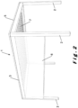
- FIG. 1 illustrates a terrace canopy 1 for a ground surface, such as a terrace or garden.
- the terrace canopy includes a number of columns 2 that support the various beams 3, 4, 5.
- the columns and beams together form frames to which wall infills 6 and/or roof coverings 7 may be attached as described below.
- the terrace canopy 1 includes three types of beams 3, 4, 5, namely:
- the beams 3, 4, 5 can also be attached to other structures, such as a wall or facade instead of just supporting the columns 2 as shown in figure 1 .
- the terrace canopy 1 is generally used for protecting an outside space, as well as for an interior space.
- the terrace canopy 1 shown in figure 2 encompasses four support columns 2 that support a frame, also called a roof frame.
- the frame is formed of two external pivot beams 3 and two tension beams 5 between which there is a roof covering 7. Between the two support columns 2 and a pivot beam 3 or tension beam 5 there may optionally be a wall infill 6.
- Wall infills 6 are typically meant to cover openings under the terrace canopy 1 between the columns 2.
- the wall infills 6 may be installed fixed or mobile.
- Mobile side walls encompass, for example, roll-up or roll-down screens and/or wall elements that are set up to slide against each other.
- Fixed installed side walls can be made of various materials, such as plastic, glass, metal, textile, wood, etc. Combinations of various wall infills 6 are also possible.
- Figure 2 illustrates a wall infill in the form of a rollable screen 6.
- the screen 6 extends between two bordering columns 2 and can be rolled from the external pivot beam 3.
- the screen 6 primarily serves as a wind and/or sun screen.
- the roof cover 7 is formed by slats that are connected to pivot beams 3 and are rotatable.
- the slats can rotate between an open position and a closed position.
- In the open position there is a space between the slats through which air, for example, can be let in to the space underneath or can leave this space underneath.
- In the closed position the slats form a closed roof so that the space below can be protected from wind and/or precipitation, such as rain, hail or snow.
- the slats are typically set up at an angle to each other toward one of the two pivot beams 3.
- the slats are typically made of a rigid material. This may be aluminum. Aluminum has many advantages as a material, it is both robust and light, resistant to poor weather conditions and requires little maintenance. Other materials are also suitable and the advantages and disadvantages of them are understood to be known to the professional.
- a slat can be produced using various techniques depending on the material, including extrusion, milling, forged, cast, welded etc. The suitable production technique is assumed to be known to the professional. Preferably, the slats are produced using an extrusion process. Additional fill-in elements may be used, such as of polycarbonate, glass, wood etc. to fill in hollow slats at least partially, such as to lend a different look to the slat.
- the slats are sliding in their open position in the terrace canopy 1 between a spread out position (shown in figure 3A ) and a stacked position (shown in figure 3B ) to increase the adjustment options regarding light incursion, radiant heat and ventilation.
- the roof construction encompasses displacement elements for sliding the transverse elements in the longitudinal direction between a spread out position and a stacked position, whereby the mutual distance between two successive transverse elements is less in the stacked position than in the spread out position.
- This type of sliding slat roof is already known in the state of the art and is described in more detail in BE 1022563 A1 . Details of and alternatives for the displacement means are assumed to be known to the professional and are only described in a limited manner here.
- the roof cover is formed by two separate sets of transverse elements, whereby a first set slides to one side of the roof construction, and the second set slides to the opposite side of the roof construction.
- the distance between two successive transverse elements is smaller in the stacked position than in the spread out position per each set of transverse elements, but not necessarily between the transverse elements of the various sets.
- the middle transverse elements of the roof construction slide away from each other during the displacement of the sets of transverse elements from their spread out to their stacked positions.
- the roof construction 10 also has a frame that is formed by two longitudinal beams 11 (e.g. the pivot beams 3 of the terrace canopy 1 of figure 2 ) and two transverse beams (e.g. the tension beams 5 of the terrace canopy 1 of figure 2 ).
- the slats 13 can be rotated toward the beams 11 around the slat axes 14 between a closed position (shown in figure 3A ) and an open position (shown in figure 3B ). Elements for the rotation of the slats 13 are assumed to be known to the professional and are not described further.
- each transverse element is formed by a slat 13, the slat axis 14 on opposite sides and the support elements 15 on which the slat axes 14 are attached.
- the displacement means are formed by a motor that drives a chain, belt or the like connected to the outside of the transverse elements to pull a side of the roof element from that outermost transverse element and in doing such drags the other transverse elements.
- This type of drive is described, for example in EP 2631384 A1 .
- the power cable 19 can extend to any of the slats 13. In this way it is possible to integrate components or to attach them to the slat 13 that needs a power supply. These components are, for example, lighting modules (such as LED lighting), a heating module, a fan, an audio module, communication media (such as Wi-Fi, Bluetooth etc.), sensors, such as for rain, wind and/or light measurement etc.
- the power cable can also be used to transport generated power, such as if a sun panel is integrated into the slat 13.
- cables can be used instead of or in addition to a power cable 19.
- Examples are cables for communication for controlling integrated electrical and/or electronic modules or for transfer of data from the integrated electrical and/or electronic modules to an external entity.
- Other possible objectives of cables and other types of cables are known to the professional and the invention does not have to be limited to a specific cable type and/or specific application of electrical and/or electronic modules that can be integrated into or attached to the slat 13.
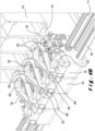
- cable guides 20 are provided between the successive transverse elements 13, 14, 15. These cable guides 20 are shown in figure 5 . There is also a first cable guide (not shown) provided between the frame and the first transverse element 13, 14, 15. The first cable guide is preferably identical to the cable guides 20, but this does not necessarily have to be the case.
- the cable guides 20 extend out between successive support elements 15, but it is also possible to attach the cable guides to the successive slats 13. In this way, there is no influence by the cable guides 20 on the rotation movement of the slats 13.
- Each cable guide 20 is equipped with two ends 21 that each have a local rarefaction 26, the rarefaction 26 forms a groove 25.
- the support elements 15 are equipped with hooks 23 that match the grooves 25. The grooves 25 and the hooks 23 together form a click connection so that the cable guides 20 can quickly and easily be attached to the support elements 15 (e.g. without the use of tools).
- the cable guides 20 have a spine 22 on which multiple hooks 23 are provided that extend toward the inside of the frame.
- the hooks 23 are L-shaped, but other shapes, such as C-shaped are also possible.
- the distance between the spine 22 and the furthest end of the hook 23 i.e. the distance d1 to the outermost leg 24 of the L-shaped hook 23
- the diameter of the power cable 19 is greater than the diameter of the power cable 19 so that there is play between the cable guide 20 and the power cable 19.
- hooks 23 there are only a limited number of hooks 23 on the spine 22.
- the number of hooks 23 is dependent on both the shape and the material used and is determined in function of the necessary force to bend the power cable 19 and the ease of attaching the power cable 19. If the number of hooks 23 is increased, it is more difficult to place the cable 19 and if there are too few hooks 23, the cable 19 is not sufficiently secured.
- the hooks 23 are placed in pairs so that the cable 19 cannot slide over or under the spine 22 even with a limited number of hooks 23.
- the cable guides 20 can also be designed as a cable duct with the advantage that the power cable 19 is seated more securely but with a longer installation time as a result.
- the cable guides 20 have the objective of avoiding the power cable 19 becoming entangled when the transverse elements 13, 14, 15 slide sideways.
- the cable guides 20 there are many designs possible for the cable guides 20. A concrete example will be illustrated below.
- the cable guides 20 are placed in a nearly horizontal surface, the surface is nearly parallel to the underside of the terrace canopy and which is located just above the displacement means and the support elements 15. It is also in this surface that the cable guides 20 fold when the slats 13 slide as shown in figure 4B . In other words, between the spread out position and the stacked position of the slats 13, the cable guides 20 fold (more generally, move) along a pre-determined path that is located in a surface, which is nearly parallel to the underside of the terrace canopy and thus does not overlap (meaning, is separate from) the displacement means. It may also be possible to make this surface sloping, such as under an angle of 45° so that the cable guides 20 gradually fold to the top side of the roof construction 10. Other pre-determined paths (along which the cable guides 20 move) that are separate from the displacement means and the support elements 15 are naturally also possible.
- the cable guides in the spread out position of the slats 13 have an arched form oriented toward the inside of the frame.
- an arch shape is advantageous and with regard to the shape with a fold line because the arch results in less sharp angles when folding.
- the arch shape is advantageous because this inherently determines the pre-determined path considering that when the slats 13 slide together, the cable guides 20 will bend further toward the orientation where the initial bending goes.
- the raise of the arc d2 of the arch shaped cable guides 20 is between 1% and 30% and preferably between 10% and 20% of the distance d3 between the ends 21 of the cable guides 20.
- the lower limit ensures that the cable guides 20, in the spread out position of the slats 13, are sufficiently bent so that they further fold in the desired direction when displacing the slats 13.
- the upper limit primarily limits the space necessary for cable guides 20 in both positions of the slats 13, because the higher the arc height, the longer the cable guide 20 is and thus more room is necessary in the roof construction for the cable guides 20 through 10 for the roof construction takes up more volume.
- a cable guide 20 with a bend zone and/or a fold zone must be greater than the distance between the ends 21 through the total length of the cable guide 20 in the installed position.
- the cable guides 20 are made in one piece using injection molding from plastic, preferably a thermoplastic, such as polyvinyl chloride (PVC), polyamide (PA), polyethylene (PE) or polypropylene (PP).
- plastic preferably a thermoplastic, such as polyvinyl chloride (PVC), polyamide (PA), polyethylene (PE) or polypropylene (PP).
- PVC polyvinyl chloride
- PA polyamide
- PE polyethylene
- PP polypropylene
- the cable guides 20 there are various designs possible for the cable guides 20.
- a hinged cable guide that is made up of two metal plates onto which the power cable 19 is attached.
- a cable guide with an accordion shape possible in the event that the power cable 19 is supple and bendable enough.
Landscapes
- Engineering & Computer Science (AREA)
- Architecture (AREA)
- Civil Engineering (AREA)
- Structural Engineering (AREA)
- Physics & Mathematics (AREA)
- Electromagnetism (AREA)
- Building Environments (AREA)
- Roof Covering Using Slabs Or Stiff Sheets (AREA)
Claims (15)
- Dachkonstruktion (10) für eine Terrassenüberdachung (1), wobei die Dachkonstruktion (10) umfasst:- einen Rahmen, der eine Querrichtung, eine Längsrichtung, eine Innenseite und eine Außenseite aufweist;- eine Dachabdeckung, die von einer Anzahl zueinander paralleler Querelemente (13, 14, 15) gebildet wird, die an der Innenseite des Rahmens positioniert sind, wobei jedes Querelement ein Trägerelement (15) und eine Lamelle (13) aufweist, wobei die Lamelle an mindestens einem Ende drehbar an einem entsprechenden Trägerelement befestigt ist, wobei die Trägerelemente am Rahmen befestigt sind; und- Verlagerungsmittel zum Verschieben der Trägerelemente in Längsrichtung zwischen einer ausgebreiteten Stellung und einer gestapelten Stellung,dadurch gekennzeichnet, dass die Dachkonstruktion weiter eine Anzahl von Kabelführungen (20) umfasst, die jeweils zwischen zwei aufeinanderfolgenden Querelementen befestigt sind und zusammen mindestens einen Teil einer Kabelführung zum Führen des Kabels vom Rahmen zu mindestens einem der Querelemente bilden.
- Dachkonstruktion (10) nach Anspruch 1, dadurch gekennzeichnet, dass die Kabelführungen (20) ein erstes Ende aufweisen, das mit einem entsprechenden ersten Querelement verbunden ist, und ein zweites Ende, das an einem entsprechenden zweiten Querelement befestigt ist, dessen Enden in der ausgebreiteten Stellung der Querelemente einen ersten Abstand voneinander aufweisen, wobei die Gesamtlänge jeder Kabelführung größer als der erste Abstand ist, wobei vorzugsweise die Kabelführungen (20) in der ausgebreiteten Stellung der Querelemente (13, 14, 15) mindestens teilweise mit einer Bogenhöhe (d2) gebogen sind, die insbesondere zwischen 1 % und 30 % und vorzugsweise zwischen 10 % und 20 % des ersten Abstands beträgt.
- Dachkonstruktion (10) nach einem der vorstehenden Ansprüche, dadurch gekennzeichnet, dass sich die Kabelführungen (20) entlang einer vorbestimmten Bahn bewegen, wenn die Querelemente zwischen ihrer ausgebreiteten Stellung und der gestapelten Stellung bewegt werden (13, 14, 15), wobei die vorbestimmte Bahn von den Bewegungselementen getrennt ist und/oder die vorbestimmte Bahn sich in einem Raum befindet, der hauptsächlich zu einer Unterseite des Rahmens parallel ist, und/oder die vorbestimmte Bahn von den Querelementen getrennt ist.
- Dachkonstruktion (10) nach einem der vorstehenden Ansprüche, dadurch gekennzeichnet, dass die Kabelführungen (20) in der ausgebreiteten Stellung der Querelemente (13, 14, 15) eine Bogenform aufweisen, die zur Innenseite des Rahmens ausgerichtet ist.
- Dachkonstruktion (10) nach einem der vorstehenden Ansprüche, dadurch gekennzeichnet, dass die Kabelführungen (20) einen Rücken (22) aufweisen, der Kabelbefestigungselemente beinhaltet, die sich zur Innenseite des Rahmens erstrecken und dafür ausgestattet sind, die aufgelisteten Kabel zu halten.
- Dachkonstruktion (10) nach Anspruch 5, dadurch gekennzeichnet, dass die Kabelbefestigungsmittel von mindestens einem der Folgenden gebildet werden: Haken (23), Klettverschluss, Kabelbinder, wobei vorzugsweise die Kabelbefestigungselemente von Haken (23), insbesondere L-förmigen oder C-förmigen Haken, gebildet werden, wobei mindestens einige der Haken einen Abstand (d1) vom Rücken aufweisen, der größer als und vorzugsweise 20 % größer als die Dicke des Kabels ist.
- Dachkonstruktion (10) nach einem der vorstehenden Ansprüche, dadurch gekennzeichnet, dass die Kabelführungen an den Enden (21) erste Befestigungselemente (25) aufweisen, und dass die Querelemente (13, 14, 15) mit zwei Befestigungselementen (23) ausgestattet sind, wobei die ersten der zwei Befestigungselemente zusammen zur Befestigung der Kabelführungen an den Querelementen vorgesehen sind.
- Dachkonstruktion (10) nach Anspruch 7, dadurch gekennzeichnet, dass die ersten und die zweiten Befestigungselemente ineinandergreifende männliche und weibliche Elemente umfassen, wobei vorzugsweise die weiblichen Elemente von einer oder mehreren Nuten und die männlichen Elemente von einem oder mehreren Haken gebildet werden, die zusammen eine Klickverbindung bilden.
- Dachkonstruktion (10) nach einem der vorstehenden Ansprüche, dadurch gekennzeichnet, dass die Kabelführungen (20) vorzugsweise einstückig, insbesondere unter Verwendung von Spritzguss, aus Kunststoff, vorzugsweise einem Thermoplast wie etwa Polyvinylchlorid (PVC), Polyamid (PA), Polyethylen (PE) oder Polypropylen (PP) oder einem Elastomer wie etwa Gummi, vorzugsweise einem thermoplastischen Elastomer oder Verbundmaterialien, vorzugsweise faserverstärkten Kunststoffen, wie etwa glasfaserverstärktem Kunststoff, hergestellt sind.
- Dachkonstruktion (10) nach einem der vorstehenden Ansprüche, dadurch gekennzeichnet, dass die Enden der Kabelführungen an den Trägerelementen befestigt sind, wobei vorzugsweise in der Stapelstellung der Querelemente zwischen den Enden der Lamellen und den Kabelführungen ein Abstand besteht.
- Dachkonstruktion (10) nach einem der vorstehenden Ansprüche, dadurch gekennzeichnet, dass mindestens eine Lamelle (13) mindestens eine elektrische Komponente aufweist, die über ein Stromkabel, das in den Kabelführungen befestigt ist, mit Strom versorgt wird.
- Dachkonstruktion (10) nach einem der vorstehenden Ansprüche, dadurch gekennzeichnet, dass die Dachkonstruktion auch das Kabel (19) aufweist, das in der Kabelführung befestigt ist.
- Dachkonstruktion (10) nach einem der vorstehenden Ansprüche, dadurch gekennzeichnet, dass die Dachkonstruktion eine zusätzliche Kabelführung aufweist, die zwischen dem Rahmen und einem Querelement befestigt ist, wobei die zusätzliche Kabelführung zusammen mit den anderen Kabelführungen (20) eine Kabelführung zum Umschließen des Kabels vom Rahmen zu mindestens einem der Querelemente bildet.
- Bausatz zum Aufbauen einer Dachkonstruktion (10) nach einem der vorstehenden Ansprüche, wobei der Satz den Rahmen, die Querelemente (13, 14, 15), die Verlagerungsmittel und die Kabelführungen (20) umschließt.
- Terrassenüberdachung (1), die die Dachkonstruktion (10) nach einem der Ansprüche 1-14 umschließt.
Applications Claiming Priority (2)
| Application Number | Priority Date | Filing Date | Title |
|---|---|---|---|
| BE20205743A BE1028728B1 (nl) | 2020-10-22 | 2020-10-22 | Dakinrichting voor een overkapping, set onderdelen voor het opbouwen van de dakinrichting, en overkapping omvattende de dakinrichting |
| PCT/IB2021/059649 WO2022084872A1 (en) | 2020-10-22 | 2021-10-20 | Roof construction for a terrace canopy, kit of parts for assembling the roof construction, and terrace canopy comprising the roof construction |
Publications (3)
| Publication Number | Publication Date |
|---|---|
| EP4232653A1 EP4232653A1 (de) | 2023-08-30 |
| EP4232653B1 true EP4232653B1 (de) | 2024-09-04 |
| EP4232653C0 EP4232653C0 (de) | 2024-09-04 |
Family
ID=73014230
Family Applications (1)
| Application Number | Title | Priority Date | Filing Date |
|---|---|---|---|
| EP21794193.9A Active EP4232653B1 (de) | 2020-10-22 | 2021-10-20 | Dachkonstruktion für ein terrassendach, bausatz zur montage der dachkonstruktion und terrassendach mit der dachkonstruktion |
Country Status (4)
| Country | Link |
|---|---|
| US (1) | US20230392382A1 (de) |
| EP (1) | EP4232653B1 (de) |
| BE (1) | BE1028728B1 (de) |
| WO (1) | WO2022084872A1 (de) |
Families Citing this family (2)
| Publication number | Priority date | Publication date | Assignee | Title |
|---|---|---|---|---|
| US12195976B2 (en) * | 2023-04-18 | 2025-01-14 | Zhejiang Jiansheng Leisure Products Co., Ltd | Outdoor louvered tent |
| IT202300013578A1 (it) * | 2023-06-29 | 2024-12-29 | Teleco Automation Srl | Dispositivo perfezionato e apparato perfezionato per una installazione a pergola o simile. |
Family Cites Families (22)
| Publication number | Priority date | Publication date | Assignee | Title |
|---|---|---|---|---|
| US4739816A (en) * | 1985-08-30 | 1988-04-26 | Levolor Lorentzen, Inc. | Venetian blind system for greenhouses |
| DE4445403B4 (de) * | 1993-12-27 | 2006-04-06 | Mirai Industry Co, Ltd. | Kabelgestell und Kabelgestellhalter |
| FR2788291B1 (fr) * | 1999-01-12 | 2001-03-09 | Bvl Serrulac | Abri escamotable |
| US7739959B2 (en) * | 2006-09-19 | 2010-06-22 | Swanson Industries, Inc. | Over/under monorail system for longwall mining operations |
| BE1019766A3 (nl) * | 2011-01-14 | 2012-12-04 | Brustor Nv | Lamel voor gebruik in een zonweringsysteem en zonweringsysteem uitgerust met zulke lamellen. |
| WO2013121448A1 (en) | 2012-02-15 | 2013-08-22 | Corradi S.P.A. | Folding outdoor awning |
| ITBO20120083A1 (it) | 2012-02-22 | 2013-08-23 | Corradi S P A | Gruppo di movimentazione per tende ad impacchettamento |
| ITBA20130060U1 (it) * | 2013-09-28 | 2015-03-28 | Tenda Service S R L | "profilato e relativo tappo per la realizzazione di una copertura ombreggiante a doppia tenda" |
| BE1021793B1 (nl) * | 2014-01-10 | 2016-01-18 | Renson Sunprotection Screens Nv | Scherminrichting |
| BE1022563B1 (nl) | 2014-10-16 | 2016-06-02 | Renson Sunprotection Screens Nv | Lamelleninrichting |
| FR3049976B1 (fr) * | 2016-04-12 | 2022-08-05 | Biossun | Installation pour couvrir et decouvrir une surface a l'aide de lames orientables automotrices attelees |
| IT201700042430A1 (it) * | 2017-04-18 | 2018-10-18 | Gibus Spa | Apparato di copertura e metodo di funzionamento di mezzi di riscaldamento di detto apparato di copertura |
| NL2019017B1 (nl) * | 2017-06-02 | 2018-12-11 | Rico Sport & Vastgoed B V | Overkapping voor het selectief overkappen van een oppervlak |
| NL2020176B1 (en) * | 2017-12-22 | 2019-07-02 | Van Der Hoeven Horticultural Projects B V | Greenhouse |
| US11149438B2 (en) * | 2018-04-30 | 2021-10-19 | Sundance Louvered Roofs Llc | Louvered panel assembly |
| IT201800009330A1 (it) * | 2018-10-10 | 2020-04-10 | Tender Srl | Dispositivo a frangisole con alette orientabili ed apribile |
| KR102053905B1 (ko) * | 2019-07-04 | 2019-12-09 | 서울시립대학교 산학협력단 | 이탈방지 구조를 갖는 연성개폐식 구조물의 트롤리 시스템 |
| BE1027574B1 (nl) * | 2019-09-12 | 2021-04-13 | Renson Sunprotection Screens | Verwarmingslamel, lamellendak omvattende dezelfde en werkwijze voor het vervaardigen daarvan |
| BE1028223B1 (nl) * | 2020-04-21 | 2021-11-22 | Renson Sunprotection Screens | Een ligger voor een overkapping |
| BE1028724B1 (nl) * | 2020-10-22 | 2022-05-24 | Renson Sunprotection Screens | Lamellendak voor een overkapping, set onderdelen voor het opbouwen van het lamellendak, en overkapping omvattende het lamellendak |
| BE1029716B1 (nl) * | 2021-08-27 | 2023-03-27 | Renson Sunprotection Screens | Een terrasoverkapping en werkwijze voor het vervaardigen daarvan |
| BE1029721B1 (nl) * | 2021-08-30 | 2023-03-27 | Renson Sunprotection Screens | Lamellendak, terrasoverkapping omvattende hetzelfde, en een set onderdelen en een werkwijze voor het opbouwen daarvan |
-
2020
- 2020-10-22 BE BE20205743A patent/BE1028728B1/nl active IP Right Grant
-
2021
- 2021-10-20 WO PCT/IB2021/059649 patent/WO2022084872A1/en not_active Ceased
- 2021-10-20 EP EP21794193.9A patent/EP4232653B1/de active Active
- 2021-10-20 US US18/033,256 patent/US20230392382A1/en active Pending
Also Published As
| Publication number | Publication date |
|---|---|
| BE1028728A1 (nl) | 2022-05-17 |
| EP4232653C0 (de) | 2024-09-04 |
| US20230392382A1 (en) | 2023-12-07 |
| WO2022084872A1 (en) | 2022-04-28 |
| BE1028728B1 (nl) | 2022-05-23 |
| EP4232653A1 (de) | 2023-08-30 |
Similar Documents
| Publication | Publication Date | Title |
|---|---|---|
| EP4139531B1 (de) | Terrassenüberdachung | |
| US12054950B2 (en) | Terrace canopy | |
| EP4232653B1 (de) | Dachkonstruktion für ein terrassendach, bausatz zur montage der dachkonstruktion und terrassendach mit der dachkonstruktion | |
| CN107407088A (zh) | 棚架覆盖物 | |
| US9140014B2 (en) | Covering device having sliding cover elements | |
| JP6509144B2 (ja) | パーゴラ式オーニング | |
| US20240125134A1 (en) | Four-device-in-one multi-function bungalow | |
| JP5038809B2 (ja) | 物干し用カバー | |
| US11959283B2 (en) | Heat and/or light regulating system | |
| EP4396421B1 (de) | Lamellendach, terrassenüberdachung damit und teilesatz und verfahren zur montage davon | |
| EP4139530B1 (de) | Terrassenüberdachung | |
| EP4330489B1 (de) | Dachanordnung für ein terrassendach und terrassendach mit der dachanordnung | |
| EP4073326A1 (de) | Dachvorrichtung für eine überdachung | |
| EP4594575A1 (de) | Terrassenüberdachung | |
| EP4352319B1 (de) | Terrassenüberdachung | |
| EP4139537B1 (de) | Terrassenüberdachung | |
| JP2008231801A (ja) | 建物 | |
| EP3732339B1 (de) | Wärme- und/oder lichtregulierungssystem | |
| JP2024013202A (ja) | 支持金具及び遮光装置 |
Legal Events
| Date | Code | Title | Description |
|---|---|---|---|
| STAA | Information on the status of an ep patent application or granted ep patent |
Free format text: STATUS: UNKNOWN |
|
| STAA | Information on the status of an ep patent application or granted ep patent |
Free format text: STATUS: THE INTERNATIONAL PUBLICATION HAS BEEN MADE |
|
| PUAI | Public reference made under article 153(3) epc to a published international application that has entered the european phase |
Free format text: ORIGINAL CODE: 0009012 |
|
| STAA | Information on the status of an ep patent application or granted ep patent |
Free format text: STATUS: REQUEST FOR EXAMINATION WAS MADE |
|
| 17P | Request for examination filed |
Effective date: 20230418 |
|
| AK | Designated contracting states |
Kind code of ref document: A1 Designated state(s): AL AT BE BG CH CY CZ DE DK EE ES FI FR GB GR HR HU IE IS IT LI LT LU LV MC MK MT NL NO PL PT RO RS SE SI SK SM TR |
|
| DAV | Request for validation of the european patent (deleted) | ||
| DAX | Request for extension of the european patent (deleted) | ||
| GRAP | Despatch of communication of intention to grant a patent |
Free format text: ORIGINAL CODE: EPIDOSNIGR1 |
|
| STAA | Information on the status of an ep patent application or granted ep patent |
Free format text: STATUS: GRANT OF PATENT IS INTENDED |
|
| INTG | Intention to grant announced |
Effective date: 20240402 |
|
| RAP3 | Party data changed (applicant data changed or rights of an application transferred) |
Owner name: RENSON OUTDOOR NV |
|
| GRAS | Grant fee paid |
Free format text: ORIGINAL CODE: EPIDOSNIGR3 |
|
| GRAA | (expected) grant |
Free format text: ORIGINAL CODE: 0009210 |
|
| STAA | Information on the status of an ep patent application or granted ep patent |
Free format text: STATUS: THE PATENT HAS BEEN GRANTED |
|
| AK | Designated contracting states |
Kind code of ref document: B1 Designated state(s): AL AT BE BG CH CY CZ DE DK EE ES FI FR GB GR HR HU IE IS IT LI LT LU LV MC MK MT NL NO PL PT RO RS SE SI SK SM TR |
|
| REG | Reference to a national code |
Ref country code: GB Ref legal event code: FG4D |
|
| REG | Reference to a national code |
Ref country code: CH Ref legal event code: EP |
|
| REG | Reference to a national code |
Ref country code: IE Ref legal event code: FG4D |
|
| REG | Reference to a national code |
Ref country code: DE Ref legal event code: R096 Ref document number: 602021018426 Country of ref document: DE |
|
| U01 | Request for unitary effect filed |
Effective date: 20240904 |
|
| U07 | Unitary effect registered |
Designated state(s): AT BE BG DE DK EE FI FR IT LT LU LV MT NL PT RO SE SI Effective date: 20240923 |
|
| U20 | Renewal fee for the european patent with unitary effect paid |
Year of fee payment: 4 Effective date: 20241126 |
|
| PG25 | Lapsed in a contracting state [announced via postgrant information from national office to epo] |
Ref country code: NO Free format text: LAPSE BECAUSE OF FAILURE TO SUBMIT A TRANSLATION OF THE DESCRIPTION OR TO PAY THE FEE WITHIN THE PRESCRIBED TIME-LIMIT Effective date: 20241204 |
|
| PG25 | Lapsed in a contracting state [announced via postgrant information from national office to epo] |
Ref country code: GR Free format text: LAPSE BECAUSE OF FAILURE TO SUBMIT A TRANSLATION OF THE DESCRIPTION OR TO PAY THE FEE WITHIN THE PRESCRIBED TIME-LIMIT Effective date: 20241205 Ref country code: PL Free format text: LAPSE BECAUSE OF FAILURE TO SUBMIT A TRANSLATION OF THE DESCRIPTION OR TO PAY THE FEE WITHIN THE PRESCRIBED TIME-LIMIT Effective date: 20240904 |
|
| PG25 | Lapsed in a contracting state [announced via postgrant information from national office to epo] |
Ref country code: HR Free format text: LAPSE BECAUSE OF FAILURE TO SUBMIT A TRANSLATION OF THE DESCRIPTION OR TO PAY THE FEE WITHIN THE PRESCRIBED TIME-LIMIT Effective date: 20240904 |
|
| PG25 | Lapsed in a contracting state [announced via postgrant information from national office to epo] |
Ref country code: RS Free format text: LAPSE BECAUSE OF FAILURE TO SUBMIT A TRANSLATION OF THE DESCRIPTION OR TO PAY THE FEE WITHIN THE PRESCRIBED TIME-LIMIT Effective date: 20241204 Ref country code: ES Free format text: LAPSE BECAUSE OF FAILURE TO SUBMIT A TRANSLATION OF THE DESCRIPTION OR TO PAY THE FEE WITHIN THE PRESCRIBED TIME-LIMIT Effective date: 20240904 |
|
| PG25 | Lapsed in a contracting state [announced via postgrant information from national office to epo] |
Ref country code: RS Free format text: LAPSE BECAUSE OF FAILURE TO SUBMIT A TRANSLATION OF THE DESCRIPTION OR TO PAY THE FEE WITHIN THE PRESCRIBED TIME-LIMIT Effective date: 20241204 Ref country code: PL Free format text: LAPSE BECAUSE OF FAILURE TO SUBMIT A TRANSLATION OF THE DESCRIPTION OR TO PAY THE FEE WITHIN THE PRESCRIBED TIME-LIMIT Effective date: 20240904 Ref country code: NO Free format text: LAPSE BECAUSE OF FAILURE TO SUBMIT A TRANSLATION OF THE DESCRIPTION OR TO PAY THE FEE WITHIN THE PRESCRIBED TIME-LIMIT Effective date: 20241204 Ref country code: HR Free format text: LAPSE BECAUSE OF FAILURE TO SUBMIT A TRANSLATION OF THE DESCRIPTION OR TO PAY THE FEE WITHIN THE PRESCRIBED TIME-LIMIT Effective date: 20240904 Ref country code: GR Free format text: LAPSE BECAUSE OF FAILURE TO SUBMIT A TRANSLATION OF THE DESCRIPTION OR TO PAY THE FEE WITHIN THE PRESCRIBED TIME-LIMIT Effective date: 20241205 Ref country code: ES Free format text: LAPSE BECAUSE OF FAILURE TO SUBMIT A TRANSLATION OF THE DESCRIPTION OR TO PAY THE FEE WITHIN THE PRESCRIBED TIME-LIMIT Effective date: 20240904 |
|
| PGFP | Annual fee paid to national office [announced via postgrant information from national office to epo] |
Ref country code: CH Payment date: 20241101 Year of fee payment: 4 |
|
| PG25 | Lapsed in a contracting state [announced via postgrant information from national office to epo] |
Ref country code: IS Free format text: LAPSE BECAUSE OF FAILURE TO SUBMIT A TRANSLATION OF THE DESCRIPTION OR TO PAY THE FEE WITHIN THE PRESCRIBED TIME-LIMIT Effective date: 20250104 |
|
| PG25 | Lapsed in a contracting state [announced via postgrant information from national office to epo] |
Ref country code: SM Free format text: LAPSE BECAUSE OF FAILURE TO SUBMIT A TRANSLATION OF THE DESCRIPTION OR TO PAY THE FEE WITHIN THE PRESCRIBED TIME-LIMIT Effective date: 20240904 |
|
| PG25 | Lapsed in a contracting state [announced via postgrant information from national office to epo] |
Ref country code: CZ Free format text: LAPSE BECAUSE OF FAILURE TO SUBMIT A TRANSLATION OF THE DESCRIPTION OR TO PAY THE FEE WITHIN THE PRESCRIBED TIME-LIMIT Effective date: 20240904 |
|
| PG25 | Lapsed in a contracting state [announced via postgrant information from national office to epo] |
Ref country code: SK Free format text: LAPSE BECAUSE OF FAILURE TO SUBMIT A TRANSLATION OF THE DESCRIPTION OR TO PAY THE FEE WITHIN THE PRESCRIBED TIME-LIMIT Effective date: 20240904 |
|
| PG25 | Lapsed in a contracting state [announced via postgrant information from national office to epo] |
Ref country code: MC Free format text: LAPSE BECAUSE OF FAILURE TO SUBMIT A TRANSLATION OF THE DESCRIPTION OR TO PAY THE FEE WITHIN THE PRESCRIBED TIME-LIMIT Effective date: 20240904 |
|
| PLBE | No opposition filed within time limit |
Free format text: ORIGINAL CODE: 0009261 |
|
| STAA | Information on the status of an ep patent application or granted ep patent |
Free format text: STATUS: NO OPPOSITION FILED WITHIN TIME LIMIT |
|
| 26N | No opposition filed |
Effective date: 20250605 |
|
| PG25 | Lapsed in a contracting state [announced via postgrant information from national office to epo] |
Ref country code: IE Free format text: LAPSE BECAUSE OF NON-PAYMENT OF DUE FEES Effective date: 20241020 |
|
| REG | Reference to a national code |
Ref country code: CH Ref legal event code: U11 Free format text: ST27 STATUS EVENT CODE: U-0-0-U10-U11 (AS PROVIDED BY THE NATIONAL OFFICE) Effective date: 20251101 |
|
| U20 | Renewal fee for the european patent with unitary effect paid |
Year of fee payment: 5 Effective date: 20251028 |