EP4139530B1 - Terrassenüberdachung - Google Patents
Terrassenüberdachung Download PDFInfo
- Publication number
- EP4139530B1 EP4139530B1 EP21727215.2A EP21727215A EP4139530B1 EP 4139530 B1 EP4139530 B1 EP 4139530B1 EP 21727215 A EP21727215 A EP 21727215A EP 4139530 B1 EP4139530 B1 EP 4139530B1
- Authority
- EP
- European Patent Office
- Prior art keywords
- profile
- wall
- terrace
- canopy
- core profile
- Prior art date
- Legal status (The legal status is an assumption and is not a legal conclusion. Google has not performed a legal analysis and makes no representation as to the accuracy of the status listed.)
- Active
Links
Images


Classifications
-
- E—FIXED CONSTRUCTIONS
- E04—BUILDING
- E04D—ROOF COVERINGS; SKY-LIGHTS; GUTTERS; ROOF-WORKING TOOLS
- E04D13/00—Special arrangements or devices in connection with roof coverings; Protection against birds; Roof drainage ; Sky-lights
- E04D13/04—Roof drainage; Drainage fittings in flat roofs, balconies or the like
- E04D13/064—Gutters
- E04D13/0643—Gutter corners
-
- E—FIXED CONSTRUCTIONS
- E04—BUILDING
- E04C—STRUCTURAL ELEMENTS; BUILDING MATERIALS
- E04C3/00—Structural elongated elements designed for load-supporting
- E04C3/30—Columns; Pillars; Struts
- E04C3/32—Columns; Pillars; Struts of metal
-
- E—FIXED CONSTRUCTIONS
- E04—BUILDING
- E04F—FINISHING WORK ON BUILDINGS, e.g. STAIRS, FLOORS
- E04F10/00—Sunshades, e.g. Florentine blinds or jalousies; Outside screens; Awnings or baldachins
-
- E—FIXED CONSTRUCTIONS
- E04—BUILDING
- E04H—BUILDINGS OR LIKE STRUCTURES FOR PARTICULAR PURPOSES; SWIMMING OR SPLASH BATHS OR POOLS; MASTS; FENCING; TENTS OR CANOPIES, IN GENERAL
- E04H6/00—Buildings for parking cars, rolling-stock, aircraft, vessels or like vehicles, e.g. garages
- E04H6/02—Small garages, e.g. for one or two cars
- E04H6/025—Small garages, e.g. for one or two cars in the form of an overhead canopy, e.g. carports
-
- E—FIXED CONSTRUCTIONS
- E04—BUILDING
- E04B—GENERAL BUILDING CONSTRUCTIONS; WALLS, e.g. PARTITIONS; ROOFS; FLOORS; CEILINGS; INSULATION OR OTHER PROTECTION OF BUILDINGS
- E04B1/00—Constructions in general; Structures which are not restricted either to walls, e.g. partitions, or floors or ceilings or roofs
- E04B1/0046—Loggias
-
- E—FIXED CONSTRUCTIONS
- E04—BUILDING
- E04D—ROOF COVERINGS; SKY-LIGHTS; GUTTERS; ROOF-WORKING TOOLS
- E04D13/00—Special arrangements or devices in connection with roof coverings; Protection against birds; Roof drainage ; Sky-lights
- E04D13/04—Roof drainage; Drainage fittings in flat roofs, balconies or the like
- E04D13/08—Down pipes; Special clamping means therefor
- E04D2013/0893—Down pipes; Special clamping means therefor incorporated in building structure
Definitions
- the present invention relates to a terrace canopy comprising a column constructed of a set of profiles.
- Such terrace canopies are usually set up to screen off or clear an outdoor area.
- screen devices are often set up near houses, restaurants, shops, etc. to screen off an outdoor terrace or the like from sunlight, precipitation and/or wind, or conversely, to temporarily allow in sunlight.
- These terrace canopies can be implemented, for example, in the form of awnings, pergolas, verandas, carports, pavilions, etc.
- Such a terrace canopy typically comprises a roof frame that is at least partially supported by columns. Exceptionally, the roof frame may also be supported by another roof construction.
- the roof frame is generally constructed of several beams that are composed into one or more frames into which a roof infill can be attached. The beams themselves are often a composition of a plurality of individual profiles.
- Such a roof frame is typically supported by four (or more) columns between which a wall infill may be provided. Likewise, less columns may be used in case the roof frame is supported by other structures, such as a wall of an already existing structure.
- the roof infill may be stationary or movable, for example, a retractable roof.
- the roof infill of a retractable roof may, for instance, consist of a rollable cloth or screen, slats that rotate around their axis, or of segments that can slide over each other.
- the segments may be panels that are partly made of (laminated) glass or plastic, such as PC or PMMA.
- the wall infill can also be stationary or movable. Examples are a rollable cloth or screen or movable, i.e. slidable or foldable, panels.
- the columns may be adapted to also provide supply cables to electrical equipment and/or to include drainage tubes for discharging precipitation and/or to comprise guide profiles for a screen.
- the column should be able to encompass all of the abovementioned functions and also be finished on the outside as aesthetically as possible.
- a known problem with such a terrace canopy is the amount of customization and/or the number of standard components that may be required to provide sufficient variation in the construction possibilities of the terrace canopy.
- BE 2013/0778 discloses a square column for supporting the beams of a terrace canopy.
- the column is constructed of a core profile and four finishing profiles which are attached thereon by means of several mounting means provided on the core profile.
- the visible outside of the column is formed by a portion of the core profile together with the finishing profiles.
- a similar column is disclosed in BE 2014/0015 .
- WO 2019/186213 A1 discloses a terrace canopy having a column with a core and covering plates each covering a side of the core profile.
- Each cover plate (or cover profile) is formed from a flat outside wall with two inwardly extending walls (spacer) having a thickened end (attachment means).
- On each corner of the core profile there is an outwardly extending flange/wall.
- the flange ends with a corner against which the inner sides of the flat outside wall of the cover plate abuts.
- the flange also has a mounting slot for receiving the thickened end on the inwardly extending wall of the cover plate.
- the terrace canopy further comprises a corner connection between the core and each beam.
- the corner connection comprises a cap mounted on each end of the beam, which cap has a hook-shaped part and an opening underneath for drainage purposes.
- the core profile is provided with a corresponding hook-shaped accessory part on each side. Both hook-shaped parts interlock with one another to attach a beam to a side of the core profile.
- cover profiles By the use of cover profiles to form the outside of the column, this immediately means that the core profile no longer forms part of the outside of the column. In other words, the functionality and visible finish of the column is entirely determined by the cover profiles. This offers a greater freedom in terms of functionality and finish compared to the column known from BE 2013/0778 , where the core profile also forms part of the outside. It is now possible, for example, to change the outer dimensions of the column by only varying the cover profiles, which is not possible with the known column. It should be clear that a plurality of cover profiles together may form one outside of the column. It is crucial that there are no visible seams between the plurality of cover profiles that together form one of the outsides of the column. In addition, the cover profiles have no bearing or supporting function since the corner connection is attached to the core profile.
- said at least one cover profile is provided with an outer wall having an outside and an inside and with at least one attachment means, in particular a pin, configured to cooperate with said mounting means for connecting the cover profile and the core profile and with a spacer between the inside and said attachment means.
- a spacer allows to vary the outer circumference of the column.
- the spacer is formed by a wall that extends between the inside of the outer wall up to said attachment means and has a predetermined length.
- This wall allows to accurately determine the length of the spacer.
- the wall is easy to manufacture during an extrusion process, with which it is therefore an integral part of the cover profile and no additional operations are required afterwards for fitting or producing the spacer.
- the wall is provided with an abutment provided to abut against the side of the core profile. This abutment improves the placement of the finishing profiles.
- said at least one cover profile is provided with an outer wall having an outside and an inside and with at least one attachment means, in particular a pin, configured to cooperate with said mounting means for connecting the cover profile and the core profile, said attachment means being directly attached to the inside of the outer wall.
- said mounting means comprises a mounting slot, which mounting slot preferably comprises a female pin connection means.
- a slot is advantageous as it can be produced during the extrusion process with which the core profile is typically manufactured.
- the core profile exhibits rotational symmetry of order three and preferably four or higher.
- the corner connection has the same rotational symmetry. Due to such a rotational symmetry, the core profile can be set up in the terrace canopy independent of the direction and the bearing capacity and strength are also the same in at least three, preferably at least four directions, which is advantageous because in a terrace canopy typically a maximum of four beams are attached to one column.
- Typical examples are core profiles with a substantially triangular, square, hexagonal, circular, etc. cross-section.
- the core profile is provided with at least four mounting means and the set comprises at least four of said cover profiles, wherein the four cover profiles, after being arranged on the core profile, substantially form a rectangle, in particular a square. In this way it is possible to hide the entire core profile from view by using four cover profiles which will typically together form a rectangle.
- a rectangle is advantageous since for a typical terrace canopy use is made of rectangular structures.
- each side of the core profile is provided with at least two mounting means.
- the use of two mounting means is advantageous in view of the fact that the use of two separate attachments between two profiles allows less clearing in the mutual positioning, which clearing may give rise to a divergent positioning, in particular due to wind loads and/or precipitation loads.
- the set comprises at least two mutually different cover profiles which are intended to be applied on a different side of the core profile.
- a first cover profile is provided with a spacer between the inside and said attachment means, wherein for a second cover profile, said attachment means is directly attached to the inside of the outer wall. In this way, space can be provided for placing a side wall infill of the terrace canopy that extends over an outer corner of the column.
- said at least one cover profile is formed by a finishing profile which cooperates with a wall guide profile. This allows to integrate the end of the screen guide, which may serve as a wall infill of the terrace canopy, into the column, such that these ends are not visible from the outside.
- the wall guide profile is provided with a rear wall from which a branch extends, wherein the rear wall and the branch together support against the core profile.
- the branch is provided at its end with a positioning means configured to engage a notch provided on the core profile.
- a positioning means configured to engage a notch provided on the core profile.
- the wall guide profile is provided with a guide chamber accessible via an opening on the outside of the cover profile, which opening is formed between the wall guide profile and the finishing profile.
- the core profile comprises a cavity
- the terrace canopy comprising a water drain positioned at least partially in the cavity of the core profile.
- the water drain is hidden from view.
- this avoids any restriction on the distance between the core profile and the cover profiles in comparison with an embodiment in which the water drain is located on the outside of the core profile and is thus positioned between the core profile and a cover profile.
- substantially includes variations of +/- 10% or less, preferably +/- 5% or less, more preferably +/- 1% or less, and more preferably +/-0.1% or less, of the specified state, insofar as the variations are applicable to function in the disclosed invention. It is to be understood that the term “substantially A” is intended to also include “A”.
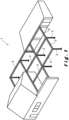
- FIG. 1 illustrates a terrace canopy 1 for a ground surface, for example a terrace or garden.
- the terrace canopy comprises a plurality of columns 2 that support different beams 3, 4, 5.
- the columns and beams together form frames to which wall infills 6 and/or roof coverings 7 can be attached, as described below.
- the terrace canopy 1 comprises three types of beams 3, 4, 5, namely:
- the beams 3, 4, 5 may be attached to other structures, for example a wall or facade, instead of resting solely on columns 2 as shown in Figure 1 .
- the terrace canopy 1 can generally be used to shield an outdoor space, as well as an indoor space.
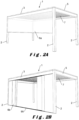
- FIGS 2A to 2J show terrace canopies 1 with alternative wall infills 6.
- the terrace canopies 1 shown have in common that four support columns 2 are provided which support a frame, also called a roof frame.
- the frame is formed from two external pivot beams 3 and two tension beams 5 in between a roof covering 7 is provided.
- the roof covering 7 is formed by slats which are rotatably attached at their front ends to pivot beams 3.
- the slats are rotatable between an open position and a closed position.
- In the open position there is an intermediate space between the slats through which, for example, air can be introduced into the underlying space or can leave this underlying space.
- In the closed position the slats form a closed roof with which the underlying space can be shielded from, for example, wind and/or precipitation, such as rain, hail or snow.
- the slats are typically arranged sloping towards one of both pivot beams 3.
- the slats are typically manufactured of a rigid material.
- This can be aluminium, for example. Aluminium has many advantages as a material, as it is at the same time robust and light-weighted, it can withstand bad weather conditions and requires little maintenance.
- other materials are also suitable and their advantages or disadvantages are assumed to be known by the skilled person.
- a slat can be produced using various techniques depending on the material, including extrusion, cutting, setting, casting, welding, etc. The appropriate production technique is assumed to be known by the skilled person.
- the slats are manufactured by means of an extrusion process.
- filler elements of, for example, polycarbonate, glass, wood, etc. can be used to fill the hollow slats at least partially, for instance to obtain a different appearance of the slat.
- the slats in their open position, may optionally be provided slidable in the terrace canopy 1, in order to further increase the control options in terms of incidence of light, radiant heat and ventilation.
- the roof covering 7 is stationary or movable.
- a movable roof covering comprises, for example, tiltable and/or slidable slats (such as described above) and/or roll-in/roll-out screens and/or slidable panels.
- the individual elements of the movable roof covering 7 in their closed position form a substantially watertight roof with which the underlying space can be screened off from, for instance, wind and/or precipitation, such as rain, hail or snow.
- This roof covering 7 is typically drained to the pivot beams 3, 4 and from there directly or via the tension beams 5 to the columns 2.
- the roof covering 7 can be at least partially opened and/or closed in order to be able to determine the incidence of light, radiant heat, ventilation, precipitation, etc. to the space below the roof covering 7 as desired.
- Wall infills 6 are typically intended to screen openings below the terrace canopy 1 between the columns 2.
- the wall infills 6 can be stationary or movable.
- Movable side walls comprise, for example, roll-in/roll-out screens and/or wall elements that are slidably arranged with respect to each other, etc.
- Stationary side walls can be manufactured of various materials, such as plastic, glass, metal, textile, wood, etc. Combinations of different wall infills 6 are also possible.
- Figure 2A illustrates a wall infill in the form of a roll-in/roll-out screen 6a.
- the screen 6a extends between two adjacent columns 2 and can be rolled out from the external pivot beam 3.
- the screen 6a mainly serves as a wind and/or sun screen.
- Figure 2B illustrates a wall infill in the form of sliding wall panels 6b.
- three panels 6b are provided on either side of the wall.
- the panels 6b are slidable in pairs (namely one on either side) in a rail provided for this purpose in the external pivot beam 3.
- a guide 99 is provided for the wall panels 6b, but this guide 99 is optional.
- Figure 2C illustrates the terrace canopy 1 of Figure 2B with the wall panels 6b in their closed position.
- the wall panels 6b are transparent and preferably made of glass. Naturally, non-transparent wall panels 6b are also possible. Their function is mainly wind and water protection, but depending on their material, sun protection is also possible.
- FIG. 2D A combination of the wall infills of Figures 2A to 2C is shown in Figure 2D .
- a double wall infill is provided, which, on the one hand, comprises a roll-in/roll-out screen 6a and, on the other hand, slidable wall panels 6b (in this case four panels 6b on either side).
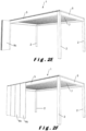
- FIG. 2E and 2F Another type of wall infill is shown in Figures 2E and 2F .
- the wall infill comprises foldable wall panels 6c.
- the wall panels 6c are foldable towards the column 2.
- Figure 2F illustrates the terrace canopy 1 of Figure 2E with the wall panels 6c in their closed position. Additional wall panels 6c are required to cover the entire wall between the columns 2.
- the wall panels 6c are transparent and preferably made of glass. Also, non-transparent wall panels 6c are also possible. Their function is mainly wind and water protection, but depending on their material, sun protection is also possible.
- the same type of wall infill, i.e. foldable wall panels 6c is also shown in Figure 2G . However, in this case, the panels 6c are located below the external pivot beam 3, while, in the embodiment of Figures 2E and 2F , the panels 6c, in their closed state, almost completely cover the external pivot beam 3.
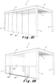
- FIGs 2H to 2J illustrate stationary wall infills 6d.
- the characteristic feature of the stationary wall infill 6d is that it is possible to have it continue uninterruptedly on the outside of a column 2. In other words, the column 2 may be hidden from view as in Figure 2H .
- the stationary wall infill 6d can also be completely transparent as in Figure 2I or partly transparent as in Figure 2J .
- the function of a stationary wall infill depends on the type and generally includes wind, water and sun protection.
- the column 2 comprises an integrally formed core portion (generally indicated by reference numeral 70).
- the profile 70 is typically manufactured of a rigid material. This can be aluminium, for example. Aluminium has many advantages as a profile material, namely, it is at the same time robust and light-weighted. However, other material, such as steel, stainless steel, wood, plastic, etc., are also suitable and their advantages or disadvantages are assumed to be known by the skilled person.
- a profile can be produced using various techniques depending on the material, including extrusion, cutting, setting, casting, welding, etc., with extrusion being the preferred technique. The appropriate production technique is assumed to be known by the skilled person.
- the profile 70 serves as a support pillar for the terrace canopy 1.
- almost the entire weight of the beams 3, 4, 5, and the elements connected therewith, such as the side walls 6 or the roof covering 7, is supported by the support pillar 70.
- the core profile 70 is hollow and the cavity 75 may be used for housing a vertical gutter (not shown).
- the core profile 70 has a substantially square shape.
- each core profile 70 has four side walls 71, each having an outside 72 and an inside 73.
- Each outside 73 is provided with two mounting means 77, in particular mounting slots, preferably female pin connection means.
- These slots 77 serve for the attachment of finishing profiles 78 by means of a corresponding connecting means 79, preferably a pin.
- a pin connection in which typically an elastic element (not shown) is present in a female element, for example a slot element, into which a male element, for example a pin, engages.
- a pin connection generally includes an elastically interlocking male and female element, but an additional elastic element may be provided for this purpose, but this is not necessarily the case. The elasticity may also arise from the design of the male and female elements.
- the pin connection 79 is only one example of a way of attaching the finishing profiles 78 to the core profile 70 and that other ways are known to the skilled person. It should also be understood that the slots 77 need not necessarily be continuous, although this is preferred since the core portion 70 is preferably made by an extrusion process. The slots 77 are symmetrically positioned with respect to the centre of a side wall 71, such that the attachment points of a finishing profile 78 to the side wall 71 are also symmetrical, which is advantageous.
- the walls 71 are also provided with a number of notches 80, 31 on their outside.
- a notch 80 is provided centrally.
- each side wall 71 is provided near a vertex thereof with a first notch 31 closest to an mounting slot 77.
- the core profile 70 is not limited to a substantially square shape.
- the four side walls 71 can be arranged in a different geometric shape, for example a rectangle or parallelogram.
- the core profile 70 does not need to be symmetrical.
- the core profile 70 may also be elliptical, in particular circular, in which case the desired number of mounting slots is then provided in the one continuous side wall comprising the core profile 70.
- each column 2 The functionality of the column 2 is determined solely by the finishing profiles 78.
- the core profile 70 is identical, as can be seen from Figures 3A to 3I .
- Each finishing profile 78 forms the entire visible outside of the column 2. This means that, for example for a column with a square cross-section, each of the four outer walls is formed by a finishing profile (or a combination of finishing profiles) without leaving a visible seam present on that outer wall.
- seams may be visible between the finishing profiles that form different outsides, i.e. seams in a vertex of the column.
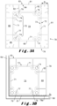
- FIG 3A illustrates a first design of a column 2 for use in a terrace canopy 1 without a wall infill.
- the column 2 is provided with four finishing profiles 78, namely one on each side wall 71.
- Each finishing profile 78 is provided with a flat outer wall 81, the outside 83 of which determines the visual appearance of the column 2.
- the finishing profile 78 hides the core profile 70 in the built-up terrace canopy 1.
- each finishing profile 78 is provided with pins 79, namely one pin per mounting slot 77.
- the pins 79 are connected to the outer wall 81 by means of walls 82 that serve as spacer.
- the length of the walls 82 determines the distance (D1 as indicated in Figure 3A and D2 as indicated in Figure 3B ) between the outside 72 of a wall 71 and the inside 84 of the outer wall 81.
- the spacer 82 may be of any length and/or that the spacer 82 does not need to be present (i.e., it has a length 0) as shown in Figure 3B .
- cavities 85 are also created. One or more of these cavities 85 may be used for the integration of electrical cables that serve to drive the wall infill 6, the roof infill 7 and/or other electrically driven elements present in the terrace canopy 1.
- the spacers 82 can also be provided by elements other than walls.
- the wall does not need to be continuous in the longitudinal direction of the finishing profile 78, optionally pins, screws, bolts, etc. may be used as spacers.
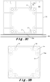
- Figure 3B illustrates a second design of a column 2 for use with a stationary wall infill 6d that continues along a vertex of the terrace canopy 1 and thus forms at least a partial infill of two side walls (see Figures 2H to 2J ). Therefore, the column 2 is suitable to be used together with the external pivot beam 3 of Figures 3B and/or 3D and/or with a tension beam 5 having such functionality.
- Figure 3C illustrates a third design of a column 2 for use with a stationary wall 6d infill in which the column 2 is located in a side wall of the terrace canopy, but is not a vertex.
- one finishing profile 78a is provided without spacers 82. Also, this finishing profile may also be omitted if the side wall 6d is not transparent.
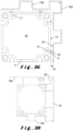
- Figure 3D illustrates a fourth design of a column 2 in which none of the finishing profiles 78a is provided with a spacer 82.
- This embodiment has the advantage that the space occupied by a column 2 is minimized such that the available space below the terrace canopy 1 is maximized.
- Figure 3E illustrates a fifth design of a column 2 for use with a screen 6a as side wall infill for one of the side walls (see Figure 2A ).
- Three of the side walls 71 are covered by means of the standard finishing profile 78'.
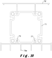
- the remaining side wall 71 is provided with an alternative finishing profile 78b which cooperates with a wall holder profile 86.
- the wall guiding profile 86 comprises a guide chamber 87 which is provided with an opening 95 in its outwardly facing wall 94.
- the screen 6a (not shown) extends through this opening 95 in its closed condition.
- the guide chamber 87 is limited by a rear wall 88 from which a branch 96 extends away from the guide chamber 87, which branch 96 is provided at its end with a positioning means, in particular a hook 89, which engages notch 31.
- the branch 96 forms a substantially right angle with the rear wall 88, which angle bears against a vertex of the core profile 70.
- a second positioning means, in particular a pin 90 is provided on a branch 97 which extends in line with the rear wall. 88. The pin 90 is received in a mounting slot 77.
- the guide chamber 87 is further limited by two side walls 91, 92.
- the one side wall 91 extends from the rear wall 88 to the outwardly facing wall 94.
- the other side wall 92 extends from the rear wall 88 towards the inside 84 of the outer wall 81 and is provided with a connecting means 93, in particular a female pin connecting element, for receiving pin 79 of the finishing profile 78b.
- the finishing profile 78b has both a pin 79 with a spacer 82 and a pin 79 without a spacer.
- the pin 79 without spacer serves for attaching to the connecting means 93 provided on the wall guide profile 86.
- Figure 3F illustrates a sixth design of a column 2 for use with a screen 6a as side wall infill for two of the side walls such that the screens 6a form an angle.
- Two of the side walls 71 are covered by means of the standard finishing profile 78'.
- the remaining side walls 71 are provided with the alternative finishing profile 78b which cooperates with the wall holder profile 86.
- Figure 3G illustrates a seventh design of a column 2 for use with a stationary wall 6d as side wall infill, which stationary wall 6d extends over the corner as shown in Figure 2H .
- two side walls 71 of the core 70 are not provided with a finishing profile and the two outsides 71 are covered with an alternative finishing profile 78d which has a crenelated shape to obtain the desired aesthetic appearance.
- Figure 3H illustrates an eighth design of a column 2 for use with a combined side wall infill, in particular a screen 6a as side wall infill as one of the side walls and stationery crenelated wall 6d as another side wall.
- one side wall 71 is provided with a crenelated finishing profile 78d
- one side wall 71 is free of a finishing
- one side wall is provided with the standard finishing 78' (this can also be used on the free wall)
- the remaining side wall 71 is provided with the alternative finishing profile 78b cooperating with the wall bracket profile 86.
- Figure 3I illustrates a ninth design of a column 2 located in a side wall of the terrace canopy 1, but which is not a vertex.
- the inside of the column 2 is finished with the standard finish 78' which can also be used on the free walls 71.
- the outwardly facing side wall of the core is finished with a stationary side wall infill 6d, formed by finishing profile 78e.
- This finishing profile is similar to the crenelated finishing profile 78d but has a modified appearance.
- the finishing profile 78e also uses pins 79 for attachment in the mounting slots 77.
Landscapes
- Engineering & Computer Science (AREA)
- Architecture (AREA)
- Civil Engineering (AREA)
- Structural Engineering (AREA)
- Building Awnings And Sunshades (AREA)
- Rod-Shaped Construction Members (AREA)
Claims (12)
- Terrassenüberdachung (1), die eine Säule (2) umfasst, die aus einem Satz Profile aufgebaut ist, wobei die Terrassenüberdachung weiter mindestens einen Balken (3; 5) und eine zwischen der Säule und dem mindestens einen Balken positionierte Eckverbindung umfasst, wobei die Säule (2) den mindestens einen Balken stützt und umfasst:- ein Kernprofil (70), wobei jede Seitenwand (71) des Kernprofils eine Innenseite (73) und eine Außenseite (74) aufweist, wobei jede Außenseite mit mindestens einem Montagemittel (77) bereitgestellt ist, das einen Montageschlitz umfasst, wobei das Kernprofil eine Rotationssymmetrie mindestens dritter Ordnung aufweist und die Eckverbindung am Kernprofil befestigt ist; und- eine Vielzahl von Abdeckprofilen (78; 78'; 78b, 86; 78d), die jeweils an einer Seite des Kernprofils mittels des Montageschlitzes in dieser Seite befestigt sind, wobei jedes Abdeckprofil mit einer äußeren Wand (81), die eine Außenseite (83) und eine Innenseite (84) aufweist, und mit mindestens einem Befestigungsmittel (79) bereitgestellt ist, das konfiguriert ist, um mit dem Montageschlitz zum Verbinden des jeweiligen Abdeckprofils mit dem Kernprofil zusammenzuwirken, wobei an jeder Seitenwand mindestens ein Abdeckprofil befestigt ist und wobei die Vielzahl von Abdeckprofilen nach dem Befestigen am Kernprofil das Kernprofil vollständig abdecken und die sichtbare Außenseite der Säule bilden, dadurch gekennzeichnet, dass die Eckverbindung eine Rotationssymmetrie aufweist, die dem Kernprofil gleicht.
- Terrassenüberdachung (1) nach Anspruch 1, dadurch gekennzeichnet, dass das mindestens eine Abdeckprofil der Vielzahl von Abdeckprofilen mit einem Abstandshalter (82) zwischen der Innenseite (84) und dem Befestigungsmittel (79) bereitgestellt ist.
- Terrassenüberdachung (1) nach Anspruch 2, dadurch gekennzeichnet, dass der Abstandshalter (82) von einer Wand gebildet wird, die sich zwischen der Innenseite (84) der äußeren Wand (81) bis zum Befestigungsmittel (79) erstreckt und eine vorbestimmte Länge (D1; D2; D3) aufweist.
- Terrassenüberdachung (1) nach Anspruch 3, dadurch gekennzeichnet, dass die Wand mit einem Anschlag (9) bereitgestellt ist, der bereitgestellt ist, um an der Seite (71) des Kernprofils (70) anzuliegen.
- Terrassenüberdachung (1) nach Anspruch 1, dadurch gekennzeichnet, dass das Befestigungsmittel (79) direkt an der Innenseite (84) der äußeren Wand (81) befestigt ist.
- Terrassenüberdachung (1) nach einem der vorstehenden Ansprüche, dadurch gekennzeichnet, dass der Montageschlitz ein weibliches Stiftverbindungsmittel umfasst und das Befestigungsmittel (79) einen Stift umfasst.
- Terrassenüberdachung (1) nach einem der vorstehenden Ansprüche, dadurch gekennzeichnet, dass das Kernprofil (70) eine Rotationssymmetrie vierter Ordnung oder höher aufweist.
- Terrassenüberdachung (1) nach einem der vorstehenden Ansprüche, dadurch gekennzeichnet, dass das Kernprofil (70) mit mindestens vier Montageschlitzen (77) bereitgestellt ist, und dadurch, dass die Säule mindestens vier Abdeckprofile (78; 78'; 78a; 78b, 86; 78d; 78e) umfasst, wobei die vier Abdeckprofile, nachdem sie am Kernprofil angelegt worden sind, im Wesentlichen ein Rechteck bilden.
- Terrassenüberdachung (1) nach einem der vorstehenden Ansprüche, dadurch gekennzeichnet, dass jede Seite (71) des Kernprofils mit mindestens zwei Montageschlitzen (77) bereitgestellt ist.
- Terrassenüberdachung (1) nach einem der vorstehenden Ansprüche, dadurch gekennzeichnet, dass die Vielzahl von Abdeckprofilen mindestens zwei voneinander unterschiedliche Abdeckprofile (78, 78', 78a, 78b, 78d, 78e) umfasst, die dazu bestimmt sind, auf einer unterschiedlichen Seite des Kernprofils positioniert zu werden, wobei ein erstes Abdeckprofil (78) der mindestens zwei voneinander unterschiedlichen Abdeckprofile mit einem Abstandshalter (82) zwischen der Innenseite (84) und dem Befestigungsmittel (79) bereitgestellt ist, wobei bei einem zweiten Abdeckprofil (78a) der mindestens zwei voneinander unterschiedlichen Abdeckprofile das Befestigungsmittel (79) direkt an der Innenseite (84) der äußeren Wand (81) befestigt ist.
- Terrassenüberdachung (1) nach einem der vorstehenden Ansprüche, dadurch gekennzeichnet, dass die Vielzahl von Abdeckprofilen ein Abschlussprofil (78b) und ein Wandführungsprofil (86) umfasst, die miteinander zusammenwirken, wobei das Wandführungsprofil (86) vorzugsweise mit einer hinteren Wand (88) bereitgestellt, aus der sich eine Abzweigung (96) erstreckt, wobei sich die hintere Wand (88) und die Abzweigung (96) gemeinsam am Kernprofil (70) abstützen, wobei die Abzweigung (96) weiter bevorzugt an ihrem Ende mit einem Positionierungsmittel (89) bereitgestellt ist, das konfiguriert ist, um in eine Kerbe (31), die am Kernprofil (70) bereitgestellt ist, in Eingriff zu kommen.
- Terrassenüberdachung (1) nach einem der vorstehenden Ansprüche, dadurch gekennzeichnet, dass das Kernprofil einen Hohlraum (75) umfasst, wobei die Terrassenüberdachung eine Wasserableitung umfasst, die mindestens teilweise im Hohlraum des Kernprofils positioniert ist.
Applications Claiming Priority (2)
| Application Number | Priority Date | Filing Date | Title |
|---|---|---|---|
| BE20205262A BE1028225B1 (nl) | 2020-04-21 | 2020-04-21 | Een set profielen voor het opbouwen van een kolom voor het ondersteunen van een overkapping |
| PCT/IB2021/053271 WO2021214670A1 (en) | 2020-04-21 | 2021-04-21 | Terrace canopy |
Publications (3)
| Publication Number | Publication Date |
|---|---|
| EP4139530A1 EP4139530A1 (de) | 2023-03-01 |
| EP4139530B1 true EP4139530B1 (de) | 2025-04-30 |
| EP4139530C0 EP4139530C0 (de) | 2025-04-30 |
Family
ID=70470720
Family Applications (1)
| Application Number | Title | Priority Date | Filing Date |
|---|---|---|---|
| EP21727215.2A Active EP4139530B1 (de) | 2020-04-21 | 2021-04-21 | Terrassenüberdachung |
Country Status (3)
| Country | Link |
|---|---|
| EP (1) | EP4139530B1 (de) |
| BE (1) | BE1028225B1 (de) |
| WO (1) | WO2021214670A1 (de) |
Families Citing this family (2)
| Publication number | Priority date | Publication date | Assignee | Title |
|---|---|---|---|---|
| DE102023102903A1 (de) * | 2023-02-07 | 2024-08-08 | SunElements GmbH | Gewächshaussystem |
| FR3150824B1 (fr) * | 2023-07-06 | 2025-08-29 | Cadiou Ind | Procédé de transformation d’un ensemble formant une pergola ou un carport |
Family Cites Families (8)
| Publication number | Priority date | Publication date | Assignee | Title |
|---|---|---|---|---|
| US4585131A (en) * | 1983-12-19 | 1986-04-29 | Amstore Corporation | Variable decor merchandising system |
| GB2238332A (en) * | 1989-11-25 | 1991-05-29 | Sun Conservatories Limited | Framing member for e.g. conservatories |
| US5904022A (en) * | 1998-01-21 | 1999-05-18 | Zadok; Yigal | Aesthetic post and beam construction having modular parts |
| CA2237210C (en) * | 1998-05-08 | 2000-01-04 | V. Paul Rossiter | Panel construction and connection system |
| US6192643B1 (en) * | 1999-01-14 | 2001-02-27 | Yigel Zadok | Modular pool enclosure system having aesthetic appeal |
| BE1021781B1 (nl) * | 2013-11-19 | 2016-01-18 | Renson Sunprotection-Screens Nv | Kolom voor het ondersteunen van een overkapping en schermconstructie omvattende een dergelijke kolom |
| BE1021793B1 (nl) * | 2014-01-10 | 2016-01-18 | Renson Sunprotection Screens Nv | Scherminrichting |
| GR1009514B (el) * | 2018-03-29 | 2019-04-24 | Cft Carbon Fiber Technologies Private Company | Συστημα σκιασης με κρυφο μηχανισμο περιστροφης περσιδων |
-
2020
- 2020-04-21 BE BE20205262A patent/BE1028225B1/nl active IP Right Grant
-
2021
- 2021-04-21 EP EP21727215.2A patent/EP4139530B1/de active Active
- 2021-04-21 WO PCT/IB2021/053271 patent/WO2021214670A1/en not_active Ceased
Also Published As
| Publication number | Publication date |
|---|---|
| BE1028225B1 (nl) | 2021-11-23 |
| EP4139530A1 (de) | 2023-03-01 |
| WO2021214670A1 (en) | 2021-10-28 |
| EP4139530C0 (de) | 2025-04-30 |
| BE1028225A1 (nl) | 2021-11-19 |
Similar Documents
| Publication | Publication Date | Title |
|---|---|---|
| EP4139531B1 (de) | Terrassenüberdachung | |
| US12054950B2 (en) | Terrace canopy | |
| EP4392626B1 (de) | Terrassenüberdachung und verfahren zur herstellung davon | |
| EP4139530B1 (de) | Terrassenüberdachung | |
| WO2021214677A1 (en) | Terrace canopy | |
| EP4139537B1 (de) | Terrassenüberdachung | |
| US12480311B2 (en) | Roof construction for a canopy, kit of parts for assembling the roof construction, and method for placing a ledstrip in the roof construction | |
| EP4352319B1 (de) | Terrassenüberdachung |
Legal Events
| Date | Code | Title | Description |
|---|---|---|---|
| STAA | Information on the status of an ep patent application or granted ep patent |
Free format text: STATUS: UNKNOWN |
|
| STAA | Information on the status of an ep patent application or granted ep patent |
Free format text: STATUS: THE INTERNATIONAL PUBLICATION HAS BEEN MADE |
|
| PUAI | Public reference made under article 153(3) epc to a published international application that has entered the european phase |
Free format text: ORIGINAL CODE: 0009012 |
|
| STAA | Information on the status of an ep patent application or granted ep patent |
Free format text: STATUS: REQUEST FOR EXAMINATION WAS MADE |
|
| 17P | Request for examination filed |
Effective date: 20220922 |
|
| AK | Designated contracting states |
Kind code of ref document: A1 Designated state(s): AL AT BE BG CH CY CZ DE DK EE ES FI FR GB GR HR HU IE IS IT LI LT LU LV MC MK MT NL NO PL PT RO RS SE SI SK SM TR |
|
| DAV | Request for validation of the european patent (deleted) | ||
| DAX | Request for extension of the european patent (deleted) | ||
| RAP3 | Party data changed (applicant data changed or rights of an application transferred) |
Owner name: RENSON OUTDOOR NV |
|
| GRAP | Despatch of communication of intention to grant a patent |
Free format text: ORIGINAL CODE: EPIDOSNIGR1 |
|
| STAA | Information on the status of an ep patent application or granted ep patent |
Free format text: STATUS: GRANT OF PATENT IS INTENDED |
|
| INTG | Intention to grant announced |
Effective date: 20241218 |
|
| GRAS | Grant fee paid |
Free format text: ORIGINAL CODE: EPIDOSNIGR3 |
|
| GRAA | (expected) grant |
Free format text: ORIGINAL CODE: 0009210 |
|
| STAA | Information on the status of an ep patent application or granted ep patent |
Free format text: STATUS: THE PATENT HAS BEEN GRANTED |
|
| AK | Designated contracting states |
Kind code of ref document: B1 Designated state(s): AL AT BE BG CH CY CZ DE DK EE ES FI FR GB GR HR HU IE IS IT LI LT LU LV MC MK MT NL NO PL PT RO RS SE SI SK SM TR |
|
| REG | Reference to a national code |
Ref country code: CH Ref legal event code: EP Ref country code: GB Ref legal event code: FG4D |
|
| REG | Reference to a national code |
Ref country code: DE Ref legal event code: R096 Ref document number: 602021030003 Country of ref document: DE |
|
| REG | Reference to a national code |
Ref country code: IE Ref legal event code: FG4D |
|
| U01 | Request for unitary effect filed |
Effective date: 20250512 |
|
| U07 | Unitary effect registered |
Designated state(s): AT BE BG DE DK EE FI FR IT LT LU LV MT NL PT RO SE SI Effective date: 20250516 |
|
| PG25 | Lapsed in a contracting state [announced via postgrant information from national office to epo] |
Ref country code: ES Free format text: LAPSE BECAUSE OF FAILURE TO SUBMIT A TRANSLATION OF THE DESCRIPTION OR TO PAY THE FEE WITHIN THE PRESCRIBED TIME-LIMIT Effective date: 20250430 |
|
| PG25 | Lapsed in a contracting state [announced via postgrant information from national office to epo] |
Ref country code: GR Free format text: LAPSE BECAUSE OF FAILURE TO SUBMIT A TRANSLATION OF THE DESCRIPTION OR TO PAY THE FEE WITHIN THE PRESCRIBED TIME-LIMIT Effective date: 20250731 Ref country code: NO Free format text: LAPSE BECAUSE OF FAILURE TO SUBMIT A TRANSLATION OF THE DESCRIPTION OR TO PAY THE FEE WITHIN THE PRESCRIBED TIME-LIMIT Effective date: 20250730 |
|
| PG25 | Lapsed in a contracting state [announced via postgrant information from national office to epo] |
Ref country code: PL Free format text: LAPSE BECAUSE OF FAILURE TO SUBMIT A TRANSLATION OF THE DESCRIPTION OR TO PAY THE FEE WITHIN THE PRESCRIBED TIME-LIMIT Effective date: 20250430 |
|
| PG25 | Lapsed in a contracting state [announced via postgrant information from national office to epo] |
Ref country code: HR Free format text: LAPSE BECAUSE OF FAILURE TO SUBMIT A TRANSLATION OF THE DESCRIPTION OR TO PAY THE FEE WITHIN THE PRESCRIBED TIME-LIMIT Effective date: 20250430 |
|
| PG25 | Lapsed in a contracting state [announced via postgrant information from national office to epo] |
Ref country code: RS Free format text: LAPSE BECAUSE OF FAILURE TO SUBMIT A TRANSLATION OF THE DESCRIPTION OR TO PAY THE FEE WITHIN THE PRESCRIBED TIME-LIMIT Effective date: 20250731 |
|
| PG25 | Lapsed in a contracting state [announced via postgrant information from national office to epo] |
Ref country code: IS Free format text: LAPSE BECAUSE OF FAILURE TO SUBMIT A TRANSLATION OF THE DESCRIPTION OR TO PAY THE FEE WITHIN THE PRESCRIBED TIME-LIMIT Effective date: 20250830 |