EP4219043A1 - Procédé et appareil à pression sous vide pour la coulée haute pression - Google Patents
Procédé et appareil à pression sous vide pour la coulée haute pression Download PDFInfo
- Publication number
- EP4219043A1 EP4219043A1 EP22382059.8A EP22382059A EP4219043A1 EP 4219043 A1 EP4219043 A1 EP 4219043A1 EP 22382059 A EP22382059 A EP 22382059A EP 4219043 A1 EP4219043 A1 EP 4219043A1
- Authority
- EP
- European Patent Office
- Prior art keywords
- vacuum
- pressure
- stage
- mould
- cavity
- Prior art date
- Legal status (The legal status is an assumption and is not a legal conclusion. Google has not performed a legal analysis and makes no representation as to the accuracy of the status listed.)
- Pending
Links
- 238000000034 method Methods 0.000 title claims abstract description 39
- 230000008569 process Effects 0.000 title claims abstract description 32
- 238000004512 die casting Methods 0.000 title claims abstract description 26
- 229910052751 metal Inorganic materials 0.000 claims abstract description 28
- 239000002184 metal Substances 0.000 claims abstract description 28
- 230000009467 reduction Effects 0.000 claims abstract description 6
- 238000004140 cleaning Methods 0.000 claims description 8
- 229910052782 aluminium Inorganic materials 0.000 claims description 5
- 229910001369 Brass Inorganic materials 0.000 claims description 3
- 239000010951 brass Substances 0.000 claims description 3
- 229910052749 magnesium Inorganic materials 0.000 claims description 3
- 229910045601 alloy Inorganic materials 0.000 claims 2
- 239000000956 alloy Substances 0.000 claims 2
- 229910052745 lead Inorganic materials 0.000 claims 2
- 229910052725 zinc Inorganic materials 0.000 claims 2
- 238000002347 injection Methods 0.000 description 13
- 239000007924 injection Substances 0.000 description 13
- 238000005266 casting Methods 0.000 description 12
- 239000007789 gas Substances 0.000 description 4
- 230000008859 change Effects 0.000 description 3
- 230000000694 effects Effects 0.000 description 3
- 238000005516 engineering process Methods 0.000 description 3
- 239000000155 melt Substances 0.000 description 3
- 230000004913 activation Effects 0.000 description 2
- 239000004411 aluminium Substances 0.000 description 2
- XAGFODPZIPBFFR-UHFFFAOYSA-N aluminium Chemical compound [Al] XAGFODPZIPBFFR-UHFFFAOYSA-N 0.000 description 2
- 239000003517 fume Substances 0.000 description 2
- 230000005484 gravity Effects 0.000 description 2
- 230000001105 regulatory effect Effects 0.000 description 2
- 229910001297 Zn alloy Inorganic materials 0.000 description 1
- 230000004075 alteration Effects 0.000 description 1
- 239000000274 aluminium melt Substances 0.000 description 1
- 238000004458 analytical method Methods 0.000 description 1
- 230000003749 cleanliness Effects 0.000 description 1
- 230000007547 defect Effects 0.000 description 1
- 238000009795 derivation Methods 0.000 description 1
- -1 dimensions Substances 0.000 description 1
- 238000006073 displacement reaction Methods 0.000 description 1
- 238000000605 extraction Methods 0.000 description 1
- 239000012530 fluid Substances 0.000 description 1
- 238000003475 lamination Methods 0.000 description 1
- 239000011133 lead Substances 0.000 description 1
- 238000004519 manufacturing process Methods 0.000 description 1
- 239000000463 material Substances 0.000 description 1
- 229910001092 metal group alloy Inorganic materials 0.000 description 1
- 239000002245 particle Substances 0.000 description 1
- 230000002028 premature Effects 0.000 description 1
- 230000003584 silencer Effects 0.000 description 1
- 238000007711 solidification Methods 0.000 description 1
- 230000008023 solidification Effects 0.000 description 1
- 238000007619 statistical method Methods 0.000 description 1
- 238000013022 venting Methods 0.000 description 1
Images


Classifications
-
- B—PERFORMING OPERATIONS; TRANSPORTING
- B22—CASTING; POWDER METALLURGY
- B22D—CASTING OF METALS; CASTING OF OTHER SUBSTANCES BY THE SAME PROCESSES OR DEVICES
- B22D17/00—Pressure die casting or injection die casting, i.e. casting in which the metal is forced into a mould under high pressure
- B22D17/14—Machines with evacuated die cavity
- B22D17/145—Venting means therefor
-
- B—PERFORMING OPERATIONS; TRANSPORTING
- B22—CASTING; POWDER METALLURGY
- B22D—CASTING OF METALS; CASTING OF OTHER SUBSTANCES BY THE SAME PROCESSES OR DEVICES
- B22D17/00—Pressure die casting or injection die casting, i.e. casting in which the metal is forced into a mould under high pressure
- B22D17/14—Machines with evacuated die cavity
-
- B—PERFORMING OPERATIONS; TRANSPORTING
- B22—CASTING; POWDER METALLURGY
- B22D—CASTING OF METALS; CASTING OF OTHER SUBSTANCES BY THE SAME PROCESSES OR DEVICES
- B22D17/00—Pressure die casting or injection die casting, i.e. casting in which the metal is forced into a mould under high pressure
- B22D17/20—Accessories: Details
- B22D17/32—Controlling equipment
Definitions
- the present invention relates to vacuum die casting methods and vacuum die casting apparatuses and especially high pressure die casting (HPDC) technology for producing thin-wall components with high performance, high dimensional accuracy, high production efficiency and considerable economic benefits for automotive and other industries.
- HPDC high pressure die casting
- JP2002-224807 A discloses a conventional High Pressure Die Casting process for preventing the air entrapment porosity from leaking into the cavity of the die out of the backside of the plunger tip.
- EP 0 051 310 A1 discloses a process which is known in the industry under the name Vacural ⁇ .
- the melt is aspirated into the casting chamber by vacuum produced in the mould and precisely controlled.
- the vacuum system is produced by a buffer vessel which the vacuum in is produced by a pump. This kind of vacuum system provide valves, filters and pressure measuring equipment to ensure the proper vacuum level.
- DE 19645 104 A1 describes a technology which permits to obtain a higher vacuum in the mould cavity thanks to two different vacuum buffer vessels, without the need to connect the vessels.
- the vacuum is generated with a dearetion valve on the mould.
- US 2009/0050289 A1 describes a technology comprising at least two vacuum phases in the total casting cycle.
- the first vacuum phase is made in the casting chamber (shoot-sleeve plus pouring area) with large cross section and higher exhaust capacity.
- the second vacuum phase is made through the casting cavity.
- EP 2 058 065 B1 describes a vacuum die casting method carrying out the casting with evacuation of a casting cavity, in which a molten metal is poured from a molten metal inlet of a plunger sleeve, followed by forming a vacuum chamber surrounding the inlet and an open end of the plunger sleeve that is on the opposite side of the die, and an evacuation of the vacuum chamber and the cavity starts before an operation of a plunger tip starts.
- the target of the present invention is to solve the problems regarding the seal performance, pressure differential, and the stability of the degree of vacuum in a short time.
- EP 1 970 145 A2 describes a method for venting molds without mechanically moving parts on a die casting mold, and neither vacuum pumps nor a vacuum tank are required.
- the mold cavity to be filled is only released when it has been vented and the casting chamber is closed.
- the vacuum is provided by a ventury device and thus is not possible to achieve vacuums below 200 mbar.
- the purpose of vacuum system of the invention in the high gravity die casting (HPDC) process is to evacuate a given volume of air from the mould cavity and the shot sleeve, thus avoiding air porosity and other defects as laminations and cold flakes in the HPDC castings.
- the invention relates to a novel vacuum die casting preferably for Al, Mg, Zn alloys, Pb or brass in order to improve the quality of the components.
- the present invention could also be applicable to any kind of die casting process without shot sleeve, such as gravity die casting processes or low pressure process.
- a first aspect of the invention relates to a vacuum pressure process for high pressure casting (in cold or hot chamber) in a mould comprising a fixed part and at least a movable part (with or without moving cores) defining inbetween a mould cavity and a shot sleeve for feeding the mould cavity with molten metal.
- the initial pressure of the mold cavity can be the atmospheric pressure.
- the process is able to extract the gases in the mould by the application of a sequence of the vacuum process in two stages during the first injection phase of the HPDC process which includes the adjustment of both the first and second vacuum levels and also their activation optimized trigger points taking into account the piston stroke during the metal injection.
- the first vacuum stage reduces the pressure in the mold cavity to a pressure between 975 mbars and 200 mbars and preferably to a pressure between 900 mbars and 450 mbars.
- the second vacuum stage reduces the pressure in the mold cavity to a pressure between 200 mbars and 0,1 mbar, preferably to a pressure between 60 mbars and 1 mbars, and more preferably between 60 and 20 mbar.
- the first stage of pressure can comprise at least an additional stage reducing the pressure to an intermediate pressure value.
- the second stage of pressure can comprise at least an additional stage reducing the pressure to an intermediate pressure value.
- the process comprises a cleaning system connected to the cavity of the mould, at an opposite position of the shot sleeve, when the mould is open, after the demoulding has finished.
- a second aspect of the invention relates to a vacuum apparatus for high pressure casting comprising
- the apparatus further comprising
- the first vacuum producing device comprises a vacuum ejector.
- the first vacuum producing device comprises a vacuum pump and a vessel.
- the second vacuum producing device comprises a vacuum pump and a vessel.
- first vacuum producing device and the second vacuum producing device are connected to a manifold.
- the apparatus of the invention can further comprise a bag cleaning system (item 18 of Figure 8 ) connected through a conduct to the cavity of the mould.
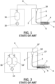
- Figure 1 is a cross-sectional view of a die-casting machine including a vacuum apparatus known in the state of art.
- the vacuum system removes the air in a unique stage from the mould with a vacuum pump 15 and a vessel 16 connected directly to the mould cavity 3 by the conduct 9.
- Figure 2 is a cross-sectional view of another die-casting machine including a vacuum apparatus known in the state of art.
- the vacuum system removes the air in two stages. In a first stage form the shot sleeve 6 through a wide cross-section connected to the line 17 and in a second stage through a connection 17' to the mould cavity 3.
- the vacuum system comprises a vacuum pump 15 and two vessel 16, 16' connected in parallel to the vacuum pump and conduct 9.
- Figure 3 shows a basic embodiment of a die-casting machine including the vacuum system 8 of the invention connected to the mould cavity 3 of the mould.
- the mould comprises a fixed part 1 and movable parts 2.
- the casting is obtained by solidification of molten metal alloy in the mould cavity 3.
- the shot sleeve 6 is provided with a filing opening 7 through which the molten metal 5 is poured before the beginning of the injection process.
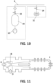
- the vacuum system 8 is formed by a first vacuum producing device comprising a vacuum ejector 11 and a second vacuum producing device comprising of a second vacuum pump 15 with a second vessel 16. Vacuum, which is controlled by the valves 13 and 14, is provided by the second vessel 16 and the ejector vacuum 11 to the manifold 12. Then, vacuum continues over the conduit 9 up to the mould cavity 3 through a deaeration valve 10, which is mounted in the mould.
- the vacuum ejector works on the Venturi principle. As can be seen in figure 11 a compressed air is supplied through connection (A) to ejectors. It flows through the venturi nozzle (B). The air is accelerated and decompressed during this process and a vacuum is created. Air is drawn in this way through the vacuum connection (D). The aspirated air and the compressed air escape through the silencer (C).
- the vacuum system 8 is formed by a first vacuum producing device comprising of a first vacuum pump 15' with a first vessel 16' and a second vacuum producing device comprising of a second vacuum pump 15 with a second vessel 16.
- Vacuum which is controlled by the valves 13 and 14, is provided by the first vessel 16' and the second vessel 16 to the manifold 12. Then, vacuum continues over the conduit 9 up to the mould cavity 3 through a deaeration valve 10, which is mounted in the mould.
- both vacuum stages are regulated by measuring the vacuum level achieved and/or air flow.
- the fist vacuum stage is set from the minimum to a maximum deaeration via a regulator valve in the air supply.
- the vacuum level in the vessel is regulated by means of a valve in charge of maintain a desired vacuum level in it. Therefore, in the first vacuum stage a first depression is achieved and with the second vacuum stage a next and final depression is obtained.
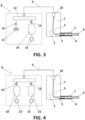
- the vacuum process comprises two stages. The method will be explained in detail with references to the figures 5A, 5B and 5C .
- Figure 5A shows the precise moment in which the metal in form of a molten mass 5 has been just poured, through the filling opening 7, into the shot sleeve 6, the injection permission signal is activated, and the first injection phase is about to happen.
- the first vacuum stage is provided by the first vacuum producing device (vacuum ejector 11 or first vessel 16' and pump 15').
- the gas, steam and fumes inside the mould are evacuated by the deareation valve 10 and through the vacuum system 8 they are expelled to the atmosphere.
- the control of the first vacuum stage is done by means of the valve 14 which is activated by the position of the piston 4 or by a delay from the injection permission signal.
- the first vacuum stage ends when the second vacuum stage is activated.
- FIG. 5B shows the precise moment in which the piston 4 is being push froward and the second vacuum stage is activated.
- This step happens during the first injection phase and before the mould filling. Thereby, the rest of the mould cavity 3 is effectively evacuated, and the maximum vacuum is achieved without a dramatic change in the pressure conditions reducing a sucking effect on the metal front.
- This second vacuum stage is controlled by means of the valve 13, which is connected to the second vessel 16, and is activated by the position of the piston 4 or by a delay from the activation of the first vacuum stage.
- the first vacuum producing device vacuum ejector 11 or first vessel 16' and pump 15'
- the valve 14 is closed via the valve 14.
- FIG. 5C shows the end of the second vacuum stage in which the mould cavity 3 has been filled, the deareation valve 10 is closed and the second vacuum producing device (15,16), in accordance with the second vacuum phase, is disconnected via the valve 13.
- Figure 6 is a graph showing an example of change of the pressure in the internal cavity, (the axis of abscissa being time and that of ordinate the internal absolute pressure) of the conventional systems disclosed in figures 1 and 2 .
- Curves C1 and C2 shown the effects of the vacuum die casting method.
- the discontinuous plotted curve represents the position of the piston 4 in the shot sleeve 6 and shows that the vacuum level is achieved before the highspeed injection starts. Both systems are able to produce the vacuum pressure curve during the injection phases, reducing the internal pressure in only one step. The main difference between them is the moment of the application of the vacuum system.
- the evacuation curve C1 represents the vacuum system of figure 2 and the evacuation curve C2 represents the vacuum system of figure 1
- the start timing of evacuation can be set earlier than the vacuum system of figure 1 . That is to say, the evacuation can be started when the piston 4 is positioned in the initial position (T0) that represent the instant in which the filling opening 7 of the shot sleeve is closed.
- the evacuation curve C2 in the vacuum system of figure 1 the evacuation starts after the piston 4 passes through the filling opening 7, the evacuation starts at the time T2, which is later than the time T1, and the pressure is higher than that of the evacuation curve C1 to avoid metal front disturbances.
- Both systems are going from the beginning of their application from the 1 atm to the minimum pressure achievable thanks to the vacuum system.
- the vacuum pressure curves of both system occurs in the piston low-speed injection phase.
- Figure 7 may represent the effect of the vacuum method of the invention in the die casting process.
- the first vacuum stage starts at T3 after T0 that represent the instant in which the filling opening 7 of the shot sleeve is closed.
- the second vacuum stage is activated at T4 and remains until at least the end of the mould filling T6.
- the system of the invention is able to produce this vacuum pressure curve during the first (plunger movement) and second (mold cavity filling) injection phases.
- the vacuum pressure curves are made in the shot sleeve low-speed injection phase but in two stages.
- the first stage is made thought the mould cavity and when the piston 4 of the shot sleeve 6 closes the filling opening 7 allowing cavity and shot sleeve dirtiness extraction, and the second stage is made as closer as possible to the commutation point (T5) to achieve the minimum pressure between the T5 and T6 (when the mould is filling with the molten metal).
- This intermediate pressure during the first vacuum stage allows to reduce and optimize the air volume inside of the mould cavity 3 before the filling of the mould without creating turbulences in the aluminium melt and breaking the melt front.
- a second and very low pressure is achievable to minimize the air content in the mould.
- first and second vacuum stages instead of first and second vacuum stages, more than two vacuum stages can be used. As a result, a smooth change in the vacuum and air flow is obtained in the metal front without generate any alteration on it.
- the vacuum ejector 11 can be in an independent system connected to the conduit 9 as it is shown in figure 10 In that case, the first gas, steam and fumes extracted from the inside of the mould are expelled directly to the atmosphere without going through the rest of the vacuum system
- the apparatus also comprises at least 3 sensors installed in the vacuum system to control the 3 main variables of the vacuum die casting process. They are the vacuum pressure, the air flow and the humidity of the air flow.
- the variables include limits in order to control the variables and guarantee the correct procedure set.
- the alarms include pollution information, if the vacuum line is operative or by the contrary is blocked. In an example, an alarm may be created if the variables are out of the range establish.
- the readings may be monitored and registered in a base data to analyse and carry out statistical analysis.
- Figures 8 and 9 show a bag cleaning system to reduce pressure drop and to ensure a good cleanliness level of the circuits and filters.
- the cleaning system comprises vessel 18 connected to the conduit 9 via a valve 19 and manifold 12.
- a vessel between 2 liters and 50 liters connected to a 4-6 bars line is opened when the mould is opened in order to clean the system.
- first, second, third, etc. have been used herein to describe several devices, elements or parameters, it will be understood that the devices, elements or parameters should not be limited by these terms since the terms are only used to distinguish one device, element or parameter from another.
- the first device could as well be named second device, and the second device could be named first device without departing from the scope of this disclosure.
Priority Applications (1)
| Application Number | Priority Date | Filing Date | Title |
|---|---|---|---|
| EP22382059.8A EP4219043A1 (fr) | 2022-01-26 | 2022-01-26 | Procédé et appareil à pression sous vide pour la coulée haute pression |
Applications Claiming Priority (1)
| Application Number | Priority Date | Filing Date | Title |
|---|---|---|---|
| EP22382059.8A EP4219043A1 (fr) | 2022-01-26 | 2022-01-26 | Procédé et appareil à pression sous vide pour la coulée haute pression |
Publications (1)
| Publication Number | Publication Date |
|---|---|
| EP4219043A1 true EP4219043A1 (fr) | 2023-08-02 |
Family
ID=80682707
Family Applications (1)
| Application Number | Title | Priority Date | Filing Date |
|---|---|---|---|
| EP22382059.8A Pending EP4219043A1 (fr) | 2022-01-26 | 2022-01-26 | Procédé et appareil à pression sous vide pour la coulée haute pression |
Country Status (1)
| Country | Link |
|---|---|
| EP (1) | EP4219043A1 (fr) |
Citations (11)
| Publication number | Priority date | Publication date | Assignee | Title |
|---|---|---|---|---|
| EP0051310A1 (fr) | 1980-11-03 | 1982-05-12 | Maschinenfabrik Müller-Weingarten AG | Appareil de moulage par injection pour la coulée de pièces |
| EP0599508A1 (fr) * | 1992-11-25 | 1994-06-01 | Ryobi Ltd. | Procédé et dispositif de décharge d'un gaz d'une coquille |
| DE19645104A1 (de) | 1996-10-31 | 1998-05-07 | Hedwig Lismont | Vakuumerzeugungs-Anlage |
| EP1057559A1 (fr) * | 1999-05-31 | 2000-12-06 | Denso Corporation | Procédé et dispositif de moulage sous pression en utilisant des agents de démoulage |
| US6298903B1 (en) * | 1998-02-19 | 2001-10-09 | Fondarex Sa | Method and apparatus for venting a diecasting mould of a diecasing machine |
| JP2002224807A (ja) | 2001-01-31 | 2002-08-13 | Toyota Motor Corp | 真空ダイカスト装置及び真空ダイカスト方法 |
| EP1970145A2 (fr) | 2007-03-13 | 2008-09-17 | Bühler Druckguss AG | Procédé pour le degasage de moules |
| US20090050289A1 (en) | 2004-11-27 | 2009-02-26 | Pfeiffer Vacuum Gmbh | Vaccuum Die-Casting Method |
| DE102008016919B3 (de) * | 2008-03-27 | 2009-11-05 | Electronics Gmbh Vertrieb Elektronischer Geräte | Verfahren zum Entlüften des Formhohlraums einer Gießvorrichtung sowie Vakuumanlage und Gießvorrichtung zur Durchführung des Verfahrens |
| EP2058065B1 (fr) | 2006-10-12 | 2011-08-17 | Toyota Jidosha Kabushiki Kaisha | Procéde coulée sous pression sous vide et dispositif coulée sous pression sous vide |
| EP3075466A1 (fr) * | 2013-11-30 | 2016-10-05 | Institute of Metal Research Chinese Academy of Sciences | Dispositif et procédé pour le formage par coulage de éléments en alliage amorphe |
-
2022
- 2022-01-26 EP EP22382059.8A patent/EP4219043A1/fr active Pending
Patent Citations (11)
| Publication number | Priority date | Publication date | Assignee | Title |
|---|---|---|---|---|
| EP0051310A1 (fr) | 1980-11-03 | 1982-05-12 | Maschinenfabrik Müller-Weingarten AG | Appareil de moulage par injection pour la coulée de pièces |
| EP0599508A1 (fr) * | 1992-11-25 | 1994-06-01 | Ryobi Ltd. | Procédé et dispositif de décharge d'un gaz d'une coquille |
| DE19645104A1 (de) | 1996-10-31 | 1998-05-07 | Hedwig Lismont | Vakuumerzeugungs-Anlage |
| US6298903B1 (en) * | 1998-02-19 | 2001-10-09 | Fondarex Sa | Method and apparatus for venting a diecasting mould of a diecasing machine |
| EP1057559A1 (fr) * | 1999-05-31 | 2000-12-06 | Denso Corporation | Procédé et dispositif de moulage sous pression en utilisant des agents de démoulage |
| JP2002224807A (ja) | 2001-01-31 | 2002-08-13 | Toyota Motor Corp | 真空ダイカスト装置及び真空ダイカスト方法 |
| US20090050289A1 (en) | 2004-11-27 | 2009-02-26 | Pfeiffer Vacuum Gmbh | Vaccuum Die-Casting Method |
| EP2058065B1 (fr) | 2006-10-12 | 2011-08-17 | Toyota Jidosha Kabushiki Kaisha | Procéde coulée sous pression sous vide et dispositif coulée sous pression sous vide |
| EP1970145A2 (fr) | 2007-03-13 | 2008-09-17 | Bühler Druckguss AG | Procédé pour le degasage de moules |
| DE102008016919B3 (de) * | 2008-03-27 | 2009-11-05 | Electronics Gmbh Vertrieb Elektronischer Geräte | Verfahren zum Entlüften des Formhohlraums einer Gießvorrichtung sowie Vakuumanlage und Gießvorrichtung zur Durchführung des Verfahrens |
| EP3075466A1 (fr) * | 2013-11-30 | 2016-10-05 | Institute of Metal Research Chinese Academy of Sciences | Dispositif et procédé pour le formage par coulage de éléments en alliage amorphe |
Similar Documents
| Publication | Publication Date | Title |
|---|---|---|
| CN101274361B (zh) | 低速真空压挤铸造工艺 | |
| CN106975738B (zh) | 真空压铸设备和高真空压铸方法 | |
| US2181157A (en) | Method and apparatus for pressure casting | |
| EP3263247B1 (fr) | Dispositif de coulée et procédé de coulée | |
| JP2519416B2 (ja) | ダイカスト法およびダイカスト装置 | |
| CN109689249B (zh) | 铸造装置用的注射装置及铸造方法 | |
| JP2005118879A (ja) | 溶融材料を処理する装置 | |
| CN101954470A (zh) | 压铸机真空压铸系统 | |
| EP3275616B1 (fr) | Dispositif et procédé pour l'aspiration de l'air dans des moules d'injection et l'expulsion ultérieure des pièces moulées | |
| CN101134235A (zh) | 铝压铸产品的制造方法及装置 | |
| CN101722295B (zh) | 一种真空压力铸造的方法及装置 | |
| CN105642862A (zh) | 一种真空压铸设备及方法 | |
| EP4219043A1 (fr) | Procédé et appareil à pression sous vide pour la coulée haute pression | |
| US6321825B1 (en) | Process and apparatus for the uphill low pressure casting of metal, particularly light metal | |
| CN101704085B (zh) | 一种压铸用的真空排气系统 | |
| JP2008246503A (ja) | 鋳造方法及びダイカストマシン | |
| JP6489500B2 (ja) | 鋳造装置及び鋳造方法 | |
| CN1229014A (zh) | 一种间接液态挤压铸造工艺及其模具 | |
| JPS642469B2 (fr) | ||
| JPS59309B2 (ja) | 金型内のガス抜きをともなった射出成形法および金型用ガス抜き装置 | |
| CN107335789B (zh) | 双独立系统压铸高真空装置 | |
| JPH08257729A (ja) | 成形部品の製造方法及びその成形装置 | |
| JPH06114533A (ja) | 吸引差圧鋳造方法 | |
| JP3655992B2 (ja) | 真空ダイカスト鋳造装置および鋳造方法 | |
| CN212398064U (zh) | 可减少铸件内部气孔数量的卧式真空压铸机 |
Legal Events
| Date | Code | Title | Description |
|---|---|---|---|
| PUAI | Public reference made under article 153(3) epc to a published international application that has entered the european phase |
Free format text: ORIGINAL CODE: 0009012 |
|
| STAA | Information on the status of an ep patent application or granted ep patent |
Free format text: STATUS: THE APPLICATION HAS BEEN PUBLISHED |
|
| AK | Designated contracting states |
Kind code of ref document: A1 Designated state(s): AL AT BE BG CH CY CZ DE DK EE ES FI FR GB GR HR HU IE IS IT LI LT LU LV MC MK MT NL NO PL PT RO RS SE SI SK SM TR |
|
| STAA | Information on the status of an ep patent application or granted ep patent |
Free format text: STATUS: REQUEST FOR EXAMINATION WAS MADE |
|
| 17P | Request for examination filed |
Effective date: 20240201 |
|
| RBV | Designated contracting states (corrected) |
Designated state(s): AL AT BE BG CH CY CZ DE DK EE ES FI FR GB GR HR HU IE IS IT LI LT LU LV MC MK MT NL NO PL PT RO RS SE SI SK SM TR |