EP4196847B1 - Kameraverschlussvorrichtung mit einem zweiseitigen hebel - Google Patents
Kameraverschlussvorrichtung mit einem zweiseitigen hebel Download PDFInfo
- Publication number
- EP4196847B1 EP4196847B1 EP21773690.9A EP21773690A EP4196847B1 EP 4196847 B1 EP4196847 B1 EP 4196847B1 EP 21773690 A EP21773690 A EP 21773690A EP 4196847 B1 EP4196847 B1 EP 4196847B1
- Authority
- EP
- European Patent Office
- Prior art keywords
- counterweight
- magnetic
- permanent magnet
- shutter device
- camera shutter
- Prior art date
- Legal status (The legal status is an assumption and is not a legal conclusion. Google has not performed a legal analysis and makes no representation as to the accuracy of the status listed.)
- Active
Links
Images




Classifications
-
- G—PHYSICS
- G03—PHOTOGRAPHY; CINEMATOGRAPHY; ANALOGOUS TECHNIQUES USING WAVES OTHER THAN OPTICAL WAVES; ELECTROGRAPHY; HOLOGRAPHY
- G03B—APPARATUS OR ARRANGEMENTS FOR TAKING PHOTOGRAPHS OR FOR PROJECTING OR VIEWING THEM; APPARATUS OR ARRANGEMENTS EMPLOYING ANALOGOUS TECHNIQUES USING WAVES OTHER THAN OPTICAL WAVES; ACCESSORIES THEREFOR
- G03B9/00—Exposure-making shutters; Diaphragms
- G03B9/08—Shutters
- G03B9/36—Sliding rigid plate
- G03B9/40—Double plate
-
- G—PHYSICS
- G03—PHOTOGRAPHY; CINEMATOGRAPHY; ANALOGOUS TECHNIQUES USING WAVES OTHER THAN OPTICAL WAVES; ELECTROGRAPHY; HOLOGRAPHY
- G03B—APPARATUS OR ARRANGEMENTS FOR TAKING PHOTOGRAPHS OR FOR PROJECTING OR VIEWING THEM; APPARATUS OR ARRANGEMENTS EMPLOYING ANALOGOUS TECHNIQUES USING WAVES OTHER THAN OPTICAL WAVES; ACCESSORIES THEREFOR
- G03B9/00—Exposure-making shutters; Diaphragms
- G03B9/08—Shutters
- G03B9/10—Blade or disc rotating or pivoting about axis normal to its plane
-
- G—PHYSICS
- G03—PHOTOGRAPHY; CINEMATOGRAPHY; ANALOGOUS TECHNIQUES USING WAVES OTHER THAN OPTICAL WAVES; ELECTROGRAPHY; HOLOGRAPHY
- G03B—APPARATUS OR ARRANGEMENTS FOR TAKING PHOTOGRAPHS OR FOR PROJECTING OR VIEWING THEM; APPARATUS OR ARRANGEMENTS EMPLOYING ANALOGOUS TECHNIQUES USING WAVES OTHER THAN OPTICAL WAVES; ACCESSORIES THEREFOR
- G03B9/00—Exposure-making shutters; Diaphragms
- G03B9/08—Shutters
-
- G—PHYSICS
- G03—PHOTOGRAPHY; CINEMATOGRAPHY; ANALOGOUS TECHNIQUES USING WAVES OTHER THAN OPTICAL WAVES; ELECTROGRAPHY; HOLOGRAPHY
- G03B—APPARATUS OR ARRANGEMENTS FOR TAKING PHOTOGRAPHS OR FOR PROJECTING OR VIEWING THEM; APPARATUS OR ARRANGEMENTS EMPLOYING ANALOGOUS TECHNIQUES USING WAVES OTHER THAN OPTICAL WAVES; ACCESSORIES THEREFOR
- G03B9/00—Exposure-making shutters; Diaphragms
- G03B9/08—Shutters
- G03B9/36—Sliding rigid plate
-
- H—ELECTRICITY
- H01—ELECTRIC ELEMENTS
- H01F—MAGNETS; INDUCTANCES; TRANSFORMERS; SELECTION OF MATERIALS FOR THEIR MAGNETIC PROPERTIES
- H01F7/00—Magnets
- H01F7/02—Permanent magnets [PM]
- H01F7/0231—Magnetic circuits with PM for power or force generation
-
- H—ELECTRICITY
- H01—ELECTRIC ELEMENTS
- H01F—MAGNETS; INDUCTANCES; TRANSFORMERS; SELECTION OF MATERIALS FOR THEIR MAGNETIC PROPERTIES
- H01F7/00—Magnets
- H01F7/06—Electromagnets; Actuators including electromagnets
- H01F7/08—Electromagnets; Actuators including electromagnets with armatures
- H01F7/16—Rectilinearly-movable armatures
Definitions
- the invention relates to a shutter device for a camera module (e.g. an IR camera module), in particular for use in various types of photographic and thermal imaging devices, as well as devices for measuring the image quality of lenses and for calibrating image sensors, which uses electromagnetic forces for opening and closing, as they are generically known from DE 27 07 175 A1 is known.
- a camera module e.g. an IR camera module
- Shutter devices are used in cameras and optical sensors to interrupt the optical beam path when necessary.
- a major challenge in the design of such shutter devices is the ongoing miniaturization of camera modules, coupled with increasing demands on heat generation, response time, lifetime, operating temperature, cost, and so on.
- Common solutions include iris diaphragms, focal plane shutters, or pivoting or guided shutter blades, which are driven electromagnetically or by a motor.
- From the DE 1 447 470 A is an electromagnetically actuated shutter mechanism in which there is a specific time interval between an opening and closing pulse.
- the shutter element is braked by stops in a specific position. After impact, it vibrates due to the remaining kinetic energy. This can lead to inaccurate exposure times or image blur due to the transmission of vibrations to the sensor.
- a shutter device for a camera module comprising a frame, two shutter blades, permanent magnets, springs, two linear sliding structures, electromagnets, and a light transmission zone.
- the two shutter blades each have two sliding cylinders, via which they are guided between two positions on the two parallel linear sliding structures, which are designed here as guide cylinders.
- the sliding cylinders on the shutter blades are permanent magnets.
- An electromagnet is arranged centrally on each guide cylinder, which, depending on the polarity, attracts or repels the sliding cylinders, which are designed as permanent magnets, against the spring forces of the compression springs arranged around the guide cylinders.
- the first shutter leaf is movable into an open position exposing the optical opening and into a closed position covering the optical opening.
- the two-sided lever is divided by a pivot point into a drive end and an output end, and can pivot about the pivot point over a pivoting angle range.
- the pivot point is arranged on a rotation axis fixed to the optical opening, and the drive end is connected to the movable part.
- the first locking blade forms a unit, firmly connected to the movable part, and a counterweight is located at the output end of the double-sided lever.
- a second weight force acts on the counterweight, causing a second torque about the rotation axis that counteracts a first torque caused by a first weight force acting on the unit.
- first locking leaf is firmly connected to the movable part and forms a unit with it and there is a counterweight at the output end of the two-sided lever, a second weight force acts on the counterweight, which causes a second torque about the axis of rotation, which counteracts a first torque caused by a first weight force acting on the unit.
- either the camera shutter device has a first permanent magnet, which has at least one magnetic surface and which is arranged within the pivot angle range in such a way that the counterweight is held in the open position and the closed position by the magnetic force of the first permanent magnet, or a first and a second permanent magnet, each having at least one magnetic surface, are present. These are assigned to the counterweight in such a way that the counterweight is held in the open position and the closed position Position is held by the magnetic force of the first or second permanent magnet.
- the counterweight consists of a ferromagnetic material and one of the at least one magnetic surface is arranged in the open position and the closed position opposite one of two different surface sections of an outer peripheral surface of the counterweight.
- the counterweight consists of a ferromagnetic material and at least two magnetic surfaces are present, wherein one of the at least two magnetic surfaces is arranged opposite a surface section of an inner circumferential surface of the counterweight in the open position and another of the at least two magnetic surfaces is arranged opposite another surface section of the inner circumferential surface of the counterweight in the closed position.
- the first permanent magnet is attached to the counterweight and a ferromagnetic armature with two end faces facing the counterweight is arranged within the pivoting angle range, wherein one of the at least one magnetic surface is arranged opposite one of the two end faces in the open position and opposite the other of the two end faces in the closed position.
- the counterweight is made of a ferromagnetic material
- the first and second permanent magnets are arranged opposite each other outside the pivot angle range.
- One of the at least one magnetic surface of the first permanent magnet is arranged opposite a surface portion of an outer peripheral surface of the counterweight in the open position
- one of the at least one magnetic surface of the second permanent magnet is arranged opposite another surface portion of the outer peripheral surface of the counterweight in the closed position.
- the respective magnetic surface and the respective surface section in the open position and the closed position each enclose a gap which is narrower than any distance of the counterweight to the first or second permanent magnet during the movement between the open and the closed position.
- the counterweight may advantageously contain a second locking blade.
- the coil body represents a linear sliding guide for the plunger.
- the camera shutter device described is obviously based on the idea of at least partially compensating the weight acting on the mass of the movable part of an electromotive drive unit with the weight acting on the shutter blade.
- the movable part and the shutter blade are connected to one another via a connecting link mounted for rotation about a pivot point.
- the pivot point is located between two pins, which are present on the shutter blade and the movable part, respectively, and are each guided in an elongated hole formed in the connecting link.
- the present invention is based on the finding that the camera shutter device can be designed more compactly and stably if the shutter blade is firmly connected directly to the movable part of the electromagnetic drive.
- a counteracting torque is generated by a counterweight, which may also contain a second shutter blade, allowing one or two shutter blades to be driven with a single electromechanical drive.
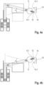
- a camera shutter device contains in all embodiments an optical opening 1, an electromagnetic drive 2 fixedly arranged thereto with a linearly guided, movable part and a first shutter blade 3 which forms a unit 23 fixedly connected to the movable part.
- a first weight force F 1 acts on the unit 23, essentially determined by the mass of the plunger 8.2 and the first closure leaf 3, while a second weight force F 2 acts on the counterweight 5, determined by its mass.
- the optical opening 1 can be a non-physically defined area through which radiation strikes a detector. It can also be the opening of an aperture or the receiving surface of a detector. It can have any shape, e.g., a round or, preferably, a rectangular shape, as shown in the following exemplary embodiments. Only the shape of the first closure leaf 3 or, as shown in a second exemplary embodiment, a second closure leaf 7, must be adapted accordingly.
- a design of the camera shutter device with a single-part shutter, i.e., one that only has the first shutter blade 3, is advantageous for use of the camera shutter device for offset adjustment in a (particularly thermal) IR camera (NUC, Non-Uniformity Correction), where it is important that the shutter, which briefly closes the optical opening 1 for at least one image acquisition cycle, has a temperature as uniform as possible on its surface.
- NUC Non-Uniformity Correction
- a two-part shutter i.e., one that has the first and second shutter blades 3, 7, which necessarily have a different relative position to existing heat sources or heat sinks within the device, a resulting temperature difference between the first and second shutter blades 3, 7 can already make the shutter unsuitable for offset adjustment.
- a first permanent magnet 6.1 or a first and a second permanent magnet 6.1, 6.2 are assigned to the counterweight 5 in order to hold the counterweight 5 in the open Position and to be held in the closed position by magnetic force when the electromagnetic drive 2 is de-energized.
- the counterweight 5 is made of a ferromagnetic material and includes a first and a second permanent magnet 6.1, 6.2 that hold the counterweight 5 in the open position and, alternatively, in the closed position when the electromagnetic drive 2 is de-energized.
- the first and second permanent magnets 6.1, 6.2 are advantageously two identical bar magnets with the same holding force and an axis of symmetry, which are aligned with each other on a straight line.
- the counterweight 5 has the shape of a round disk, the center of which lies on the straight line in the open and closed positions.
- the magnetic surfaces 14 facing the counterweight 5, here containing, for example, the north or south pole of the first or second permanent magnet 6.1, 6.2, respectively, are typically flat surfaces or, advantageously, cylindrical segment surfaces with a slightly larger radius than that of the counterweight 5.
- the pivot angle range ⁇ is advantageously limited by the stroke length or by mechanical stops, against which, for example, the movable part or the two-sided lever 4 strikes.
- the electromagnetic drive 2 is implemented here by a lifting magnet 8, with a coil 8.1 and a ferromagnetic or permanent-magnetic armature core 8.2.1, which is attached to a plunger 8.2, which here represents the movable part of the electromagnetic drive 2.
- the movement of the armature core 8.2.1 occurs over a stroke length that is advantageously greater than half the overall length of the camera shutter device.
- the overall length is the maximum extension of the camera shutter device in the direction of movement of the armature core 8.2.1.
- the connection to the two-sided lever 4 and the unit 23 is established via a pin-and-slot connection.
- the Movement of the armature core 8.2.1 is transmitted at a transmission ratio of 1:1.
- the winding 8.1.2 is designed as a winding with at least two phases. It can consist of at least two bipolar individual windings arranged one behind the other on the coil body 8.1.1 or of unipolar winding pairs whose two halves are wound in opposite directions. A temporally and thus phase-shifted control leads to a comparatively longer stroke length than would be achievable with a coil with only one individual winding of the same winding length.
- a longer stroke length is also achieved when using a permanent magnetic armature core 8.2.1 and the alternating use of attractive and repulsive forces by reversing the direction of the magnetic field of the coil 8.1.
- the current flow is reversed; in the case of unipolar winding pairs, one or the other half of the winding is alternately energized.
- the coil 8.1 is partially or completely enclosed by a ferromagnetic housing 11, whereby a magnetic flux arising inside the coil 8.1 is increased and a stray field arising around the coil 8.1 is reduced.
- the first permanent magnet 6.1 is fixedly attached to the counterweight 5 within the pivot angle range ⁇ and is radially aligned with the pivot point P, which is why the counterweight 5 itself does not have to be made of a ferromagnetic material in this case.
- a ferromagnetic armature 13, with two flat end faces 13.1 facing the pivot point P, is also statically fixed within the pivot angle range ⁇ . In the open position and the closed position, one of the end faces 13.1 is opposite an identical one of the magnetic surfaces 14 and forms an identical gap 12.
- the counterweight 5 contains a second closure leaf 7. This embodiment differs from the first embodiment only in the design of the counterweight 5.
- it is comparable to the unit 23, which is connected to the drive-side end 4.1 of the double-sided lever 4 via a pin-and-slot connection, and is rotatably connected to the output-side end 4.2 of the double-sided lever 4 via a pin-and-slot connection, whereby the length of the second lever arm r 2 also changes during the movement sequence.
- the second locking leaf 7 is advantageously attached to a connecting rod 9, comparable to the connection of the first locking leaf 3 to the tappet 8.2.
- the connecting rod 9 is made of a ferromagnetic material and can thus be held by the first or second permanent magnets 6.1, 6.2. As with the plunger 8.2, the connecting rod 9 has a pin that is guided in an elongated hole formed on the two-sided lever 4.
- a sliding guide 10 is provided for linear guidance of the connecting rod 9.
- the first and second closure leaves 3, 7 are moved simultaneously in opposite directions by a single electromagnetic drive 2.
- an advantageous embodiment of the camera shutter device with only a first shutter blade 3 is significantly more compact compared to the prior art.
Landscapes
- Physics & Mathematics (AREA)
- General Physics & Mathematics (AREA)
- Electromagnetism (AREA)
- Engineering & Computer Science (AREA)
- Power Engineering (AREA)
- Shutters For Cameras (AREA)
Applications Claiming Priority (2)
| Application Number | Priority Date | Filing Date | Title |
|---|---|---|---|
| DE102020121173.2A DE102020121173B4 (de) | 2020-08-12 | 2020-08-12 | Kameraverschlussvorrichtung mit einem zweiseitigen Hebel |
| PCT/DE2021/100672 WO2022033632A1 (de) | 2020-08-12 | 2021-08-05 | Kameraverschlussvorrichtung mit einem zweiseitigen hebel |
Publications (2)
| Publication Number | Publication Date |
|---|---|
| EP4196847A1 EP4196847A1 (de) | 2023-06-21 |
| EP4196847B1 true EP4196847B1 (de) | 2025-04-16 |
Family
ID=77897427
Family Applications (1)
| Application Number | Title | Priority Date | Filing Date |
|---|---|---|---|
| EP21773690.9A Active EP4196847B1 (de) | 2020-08-12 | 2021-08-05 | Kameraverschlussvorrichtung mit einem zweiseitigen hebel |
Country Status (10)
| Country | Link |
|---|---|
| US (1) | US12228851B2 (pl) |
| EP (1) | EP4196847B1 (pl) |
| JP (1) | JP7784415B2 (pl) |
| KR (1) | KR20230049651A (pl) |
| CN (1) | CN116134376B (pl) |
| DE (1) | DE102020121173B4 (pl) |
| DK (1) | DK4196847T3 (pl) |
| ES (1) | ES3036159T3 (pl) |
| PL (1) | PL4196847T3 (pl) |
| WO (1) | WO2022033632A1 (pl) |
Citations (3)
| Publication number | Priority date | Publication date | Assignee | Title |
|---|---|---|---|---|
| US4367931A (en) * | 1979-09-17 | 1983-01-11 | Canon Kabushiki Kaisha | Electromagnetically driven diaphragm device |
| US4410249A (en) * | 1981-05-08 | 1983-10-18 | Canon Kabushiki Kaisha | Camera with electromagnetically operated shutter |
| US7513702B2 (en) * | 2005-11-16 | 2009-04-07 | Va, Inc. | Non-contact shutter activation system and method |
Family Cites Families (23)
| Publication number | Priority date | Publication date | Assignee | Title |
|---|---|---|---|---|
| DE1447470A1 (de) | 1964-04-16 | 1969-03-20 | Compur Werk Gmbh & Co | Photographsiche Kamera mit elektromagnetischer Verschluss-Betaetigung |
| JPS5019930A (pl) * | 1973-06-28 | 1975-03-03 | ||
| CH558542A (de) * | 1973-07-19 | 1975-01-31 | Sinar Ag Schaffhausen | Verschlusseinrichtung fuer photographische kamera. |
| JPS5538366B2 (pl) | 1974-03-13 | 1980-10-03 | ||
| JPS5710408B2 (pl) * | 1974-04-25 | 1982-02-26 | ||
| US4171917A (en) * | 1974-07-02 | 1979-10-23 | Centre De Recherches Metallurgiques-Centrum Voor Research In De Metallurgie | Determining the profile of a surface of an object |
| US4121235A (en) | 1975-09-23 | 1978-10-17 | Fuji Photo Film Co., Ltd. | Electromagnetically operated shutter mechanism |
| DE2642601C2 (de) | 1975-09-23 | 1984-08-16 | Fuji Photo Film Co., Ltd., Minami Ashigara, Kanagawa | Elektromagnetisch betätigter Verschlußmechanismus |
| JPS5290037U (pl) * | 1975-12-27 | 1977-07-05 | ||
| JPS5293322A (en) | 1976-02-02 | 1977-08-05 | Fuji Photo Film Co Ltd | Electromagnetic shutter |
| JPS52117124A (en) * | 1976-03-26 | 1977-10-01 | Fuji Photo Film Co Ltd | Two-blade shutter |
| JPS52100229A (en) * | 1976-02-18 | 1977-08-23 | Fuji Photo Film Co Ltd | Shutter blade drive means |
| US4112450A (en) | 1976-02-18 | 1978-09-05 | Fuji Photo Film Co., Ltd. | Shutter device for a photographic camera |
| JPS55149923A (en) * | 1979-05-10 | 1980-11-21 | Canon Inc | Electromagnetically driven shutter |
| JP2725246B2 (ja) * | 1989-02-07 | 1998-03-11 | 富士写真フイルム株式会社 | シャッタ装置 |
| GB8919698D0 (en) | 1989-08-31 | 1989-10-11 | Yu Cheung L | Camera shutter actuating device |
| JPH0615021U (ja) * | 1992-07-22 | 1994-02-25 | ティーディーケイ株式会社 | アクチュエータ |
| SE9700434L (sv) * | 1997-02-06 | 1998-08-07 | Hasselblad Ab Victor | Elektromagnetiskt förskjutningsorgan |
| DE102010023167B4 (de) * | 2010-06-07 | 2014-06-26 | Dräger Safety AG & Co. KGaA | Wärmebildkamera mit einer schnellen elektromechanischen Verschlussvorrichtung |
| CN202748581U (zh) | 2012-09-13 | 2013-02-20 | 烟台睿创微纳技术有限公司 | 一种用于相机模块的快门驱动装置 |
| US8956059B1 (en) | 2014-06-26 | 2015-02-17 | Melles-Griot | Shutter with power-free magnetic detent |
| CN204028532U (zh) | 2014-08-12 | 2014-12-17 | 烟台艾睿光电科技有限公司 | 一种焦平面快门结构 |
| US9851553B1 (en) | 2016-06-28 | 2017-12-26 | Melles Griot | Shutter with linear actuator |
-
2020
- 2020-08-12 DE DE102020121173.2A patent/DE102020121173B4/de active Active
-
2021
- 2021-08-05 WO PCT/DE2021/100672 patent/WO2022033632A1/de not_active Ceased
- 2021-08-05 US US18/006,809 patent/US12228851B2/en active Active
- 2021-08-05 ES ES21773690T patent/ES3036159T3/es active Active
- 2021-08-05 PL PL21773690.9T patent/PL4196847T3/pl unknown
- 2021-08-05 EP EP21773690.9A patent/EP4196847B1/de active Active
- 2021-08-05 JP JP2023508021A patent/JP7784415B2/ja active Active
- 2021-08-05 KR KR1020237006222A patent/KR20230049651A/ko active Pending
- 2021-08-05 CN CN202180057473.3A patent/CN116134376B/zh active Active
- 2021-08-05 DK DK21773690.9T patent/DK4196847T3/da active
Patent Citations (3)
| Publication number | Priority date | Publication date | Assignee | Title |
|---|---|---|---|---|
| US4367931A (en) * | 1979-09-17 | 1983-01-11 | Canon Kabushiki Kaisha | Electromagnetically driven diaphragm device |
| US4410249A (en) * | 1981-05-08 | 1983-10-18 | Canon Kabushiki Kaisha | Camera with electromagnetically operated shutter |
| US7513702B2 (en) * | 2005-11-16 | 2009-04-07 | Va, Inc. | Non-contact shutter activation system and method |
Also Published As
| Publication number | Publication date |
|---|---|
| DE102020121173A1 (de) | 2022-02-17 |
| WO2022033632A1 (de) | 2022-02-17 |
| DE102020121173B4 (de) | 2024-06-27 |
| CN116134376A (zh) | 2023-05-16 |
| ES3036159T3 (en) | 2025-09-15 |
| JP7784415B2 (ja) | 2025-12-11 |
| PL4196847T3 (pl) | 2025-09-01 |
| EP4196847A1 (de) | 2023-06-21 |
| KR20230049651A (ko) | 2023-04-13 |
| US20230273505A1 (en) | 2023-08-31 |
| JP2023537011A (ja) | 2023-08-30 |
| CN116134376B (zh) | 2026-02-27 |
| DK4196847T3 (da) | 2025-08-04 |
| US12228851B2 (en) | 2025-02-18 |
Similar Documents
| Publication | Publication Date | Title |
|---|---|---|
| DE2728824C3 (de) | Photographischer Kameraverschluß | |
| DE19713276C2 (de) | Vorrichtung zum Positionieren von Bauelementen innerhalb endoskopischer Systeme | |
| DE4302389C2 (de) | Blendenverschluß für ein Objektiv | |
| DE2358929C3 (de) | Verschlußeinrichtung für photographische Kamera | |
| EP4196847B1 (de) | Kameraverschlussvorrichtung mit einem zweiseitigen hebel | |
| DE3017893A1 (de) | Elektromagnetisch betaetigter kameraverschluss | |
| DE102012213052B4 (de) | Betätigungsmagnet zum Bewegen einer Verschlussnadel einer Heißkanaldüse eines Spritzgusswerkzeugs | |
| DE3003462C2 (de) | Elektrodynamischer Antrieb für einen Verschluß einer Kamera | |
| EP4139742B1 (de) | Kameraverschlussvorrichtung mit permanentmagneten | |
| DE3034643C2 (de) | Blendensteuerung für eine Kamera | |
| DE68924217T2 (de) | Linearantrieb. | |
| EP3500149B1 (de) | Elektromagnetischer aktuator für ein chirurgisches instrument | |
| EP1719009B1 (de) | Verfahren zur steuerung eines lichtverschlusses | |
| DE102008038599A1 (de) | Sensorgelenk und Verfahren zum Betreiben eines Sensors | |
| DE2031565B2 (de) | Elektromagnetischer Lamellenan trieb an fotografischen Objektivver Schlüssen | |
| DE10029444B4 (de) | Optische Anordnung | |
| DE112013002328T5 (de) | Bildstabilisierungsvorrichtung, optische Vorrichtung und Bilderfassungsvorrichtung | |
| DE2005635B2 (de) | Elektronischer verschluss fuer eine photographische kamera | |
| DE4409889C2 (de) | Drehmagnet, insbesondere Regelmagnet | |
| DE1107505B (de) | Photographische Kamera mit gekuppeltem Belichtungsmesser | |
| DE102019111591A1 (de) | Elektromagnetischer Aktor zur Kupplungsbetätigung und rotierende Verschiebeeinrichtung einen solchen elektromagnetischen Aktor enthaltend | |
| DE973996C (de) | Photographische Kamera mit durch Bajonettverriegelungsring befestigbaren Wechselobjektiven | |
| EP0026273A2 (de) | Vorrichtung zur blendensteuerung | |
| DE19947378A1 (de) | Verstellvorrichtung für ein Objektiv mit einem axial beweglichen Optikglied | |
| DE1160298B (de) | Fassung fuer photographische Objektive mit einer durch magnetische Kraftfelder betaetigbaren Vorwaehlblende |
Legal Events
| Date | Code | Title | Description |
|---|---|---|---|
| STAA | Information on the status of an ep patent application or granted ep patent |
Free format text: STATUS: UNKNOWN |
|
| STAA | Information on the status of an ep patent application or granted ep patent |
Free format text: STATUS: THE INTERNATIONAL PUBLICATION HAS BEEN MADE |
|
| PUAI | Public reference made under article 153(3) epc to a published international application that has entered the european phase |
Free format text: ORIGINAL CODE: 0009012 |
|
| STAA | Information on the status of an ep patent application or granted ep patent |
Free format text: STATUS: REQUEST FOR EXAMINATION WAS MADE |
|
| 17P | Request for examination filed |
Effective date: 20230306 |
|
| AK | Designated contracting states |
Kind code of ref document: A1 Designated state(s): AL AT BE BG CH CY CZ DE DK EE ES FI FR GB GR HR HU IE IS IT LI LT LU LV MC MK MT NL NO PL PT RO RS SE SI SK SM TR |
|
| DAV | Request for validation of the european patent (deleted) | ||
| DAX | Request for extension of the european patent (deleted) | ||
| GRAP | Despatch of communication of intention to grant a patent |
Free format text: ORIGINAL CODE: EPIDOSNIGR1 |
|
| STAA | Information on the status of an ep patent application or granted ep patent |
Free format text: STATUS: GRANT OF PATENT IS INTENDED |
|
| INTG | Intention to grant announced |
Effective date: 20250102 |
|
| GRAS | Grant fee paid |
Free format text: ORIGINAL CODE: EPIDOSNIGR3 |
|
| GRAA | (expected) grant |
Free format text: ORIGINAL CODE: 0009210 |
|
| STAA | Information on the status of an ep patent application or granted ep patent |
Free format text: STATUS: THE PATENT HAS BEEN GRANTED |
|
| AK | Designated contracting states |
Kind code of ref document: B1 Designated state(s): AL AT BE BG CH CY CZ DE DK EE ES FI FR GB GR HR HU IE IS IT LI LT LU LV MC MK MT NL NO PL PT RO RS SE SI SK SM TR |
|
| REG | Reference to a national code |
Ref country code: GB Ref legal event code: FG4D Free format text: NOT ENGLISH |
|
| REG | Reference to a national code |
Ref country code: CH Ref legal event code: EP |
|
| REG | Reference to a national code |
Ref country code: IE Ref legal event code: FG4D Free format text: LANGUAGE OF EP DOCUMENT: GERMAN |
|
| REG | Reference to a national code |
Ref country code: DE Ref legal event code: R096 Ref document number: 502021007239 Country of ref document: DE |
|
| REG | Reference to a national code |
Ref country code: DK Ref legal event code: T3 Effective date: 20250728 |
|
| REG | Reference to a national code |
Ref country code: SE Ref legal event code: TRGR |
|
| REG | Reference to a national code |
Ref country code: NL Ref legal event code: MP Effective date: 20250416 |
|
| PG25 | Lapsed in a contracting state [announced via postgrant information from national office to epo] |
Ref country code: NL Free format text: LAPSE BECAUSE OF FAILURE TO SUBMIT A TRANSLATION OF THE DESCRIPTION OR TO PAY THE FEE WITHIN THE PRESCRIBED TIME-LIMIT Effective date: 20250416 |
|
| REG | Reference to a national code |
Ref country code: ES Ref legal event code: FG2A Ref document number: 3036159 Country of ref document: ES Kind code of ref document: T3 Effective date: 20250915 |
|
| PG25 | Lapsed in a contracting state [announced via postgrant information from national office to epo] |
Ref country code: FI Free format text: LAPSE BECAUSE OF FAILURE TO SUBMIT A TRANSLATION OF THE DESCRIPTION OR TO PAY THE FEE WITHIN THE PRESCRIBED TIME-LIMIT Effective date: 20250416 Ref country code: PT Free format text: LAPSE BECAUSE OF FAILURE TO SUBMIT A TRANSLATION OF THE DESCRIPTION OR TO PAY THE FEE WITHIN THE PRESCRIBED TIME-LIMIT Effective date: 20250818 |
|
| PGFP | Annual fee paid to national office [announced via postgrant information from national office to epo] |
Ref country code: ES Payment date: 20250917 Year of fee payment: 5 |
|
| PGFP | Annual fee paid to national office [announced via postgrant information from national office to epo] |
Ref country code: DE Payment date: 20250819 Year of fee payment: 5 Ref country code: DK Payment date: 20250821 Year of fee payment: 5 |
|
| REG | Reference to a national code |
Ref country code: LT Ref legal event code: MG9D |
|
| PG25 | Lapsed in a contracting state [announced via postgrant information from national office to epo] |
Ref country code: NO Free format text: LAPSE BECAUSE OF FAILURE TO SUBMIT A TRANSLATION OF THE DESCRIPTION OR TO PAY THE FEE WITHIN THE PRESCRIBED TIME-LIMIT Effective date: 20250716 Ref country code: GR Free format text: LAPSE BECAUSE OF FAILURE TO SUBMIT A TRANSLATION OF THE DESCRIPTION OR TO PAY THE FEE WITHIN THE PRESCRIBED TIME-LIMIT Effective date: 20250717 |
|
| PGFP | Annual fee paid to national office [announced via postgrant information from national office to epo] |
Ref country code: PL Payment date: 20250724 Year of fee payment: 5 Ref country code: IT Payment date: 20250829 Year of fee payment: 5 |
|
| PG25 | Lapsed in a contracting state [announced via postgrant information from national office to epo] |
Ref country code: BG Free format text: LAPSE BECAUSE OF FAILURE TO SUBMIT A TRANSLATION OF THE DESCRIPTION OR TO PAY THE FEE WITHIN THE PRESCRIBED TIME-LIMIT Effective date: 20250416 |
|
| PGFP | Annual fee paid to national office [announced via postgrant information from national office to epo] |
Ref country code: GB Payment date: 20250822 Year of fee payment: 5 |
|
| PG25 | Lapsed in a contracting state [announced via postgrant information from national office to epo] |
Ref country code: HR Free format text: LAPSE BECAUSE OF FAILURE TO SUBMIT A TRANSLATION OF THE DESCRIPTION OR TO PAY THE FEE WITHIN THE PRESCRIBED TIME-LIMIT Effective date: 20250416 |
|
| PGFP | Annual fee paid to national office [announced via postgrant information from national office to epo] |
Ref country code: FR Payment date: 20250821 Year of fee payment: 5 Ref country code: AT Payment date: 20251020 Year of fee payment: 5 |
|
| PGFP | Annual fee paid to national office [announced via postgrant information from national office to epo] |
Ref country code: CH Payment date: 20250901 Year of fee payment: 5 Ref country code: SE Payment date: 20250821 Year of fee payment: 5 |
|
| PG25 | Lapsed in a contracting state [announced via postgrant information from national office to epo] |
Ref country code: RS Free format text: LAPSE BECAUSE OF FAILURE TO SUBMIT A TRANSLATION OF THE DESCRIPTION OR TO PAY THE FEE WITHIN THE PRESCRIBED TIME-LIMIT Effective date: 20250716 |
|
| PGFP | Annual fee paid to national office [announced via postgrant information from national office to epo] |
Ref country code: CZ Payment date: 20250723 Year of fee payment: 5 |
|
| PG25 | Lapsed in a contracting state [announced via postgrant information from national office to epo] |
Ref country code: IS Free format text: LAPSE BECAUSE OF FAILURE TO SUBMIT A TRANSLATION OF THE DESCRIPTION OR TO PAY THE FEE WITHIN THE PRESCRIBED TIME-LIMIT Effective date: 20250816 |
|
| PG25 | Lapsed in a contracting state [announced via postgrant information from national office to epo] |
Ref country code: LV Free format text: LAPSE BECAUSE OF FAILURE TO SUBMIT A TRANSLATION OF THE DESCRIPTION OR TO PAY THE FEE WITHIN THE PRESCRIBED TIME-LIMIT Effective date: 20250416 |
|
| PG25 | Lapsed in a contracting state [announced via postgrant information from national office to epo] |
Ref country code: SM Free format text: LAPSE BECAUSE OF FAILURE TO SUBMIT A TRANSLATION OF THE DESCRIPTION OR TO PAY THE FEE WITHIN THE PRESCRIBED TIME-LIMIT Effective date: 20250416 |
|
| REG | Reference to a national code |
Ref country code: DE Ref legal event code: R097 Ref document number: 502021007239 Country of ref document: DE |
|
| PG25 | Lapsed in a contracting state [announced via postgrant information from national office to epo] |
Ref country code: EE Free format text: LAPSE BECAUSE OF FAILURE TO SUBMIT A TRANSLATION OF THE DESCRIPTION OR TO PAY THE FEE WITHIN THE PRESCRIBED TIME-LIMIT Effective date: 20250416 |
|
| PG25 | Lapsed in a contracting state [announced via postgrant information from national office to epo] |
Ref country code: SK Free format text: LAPSE BECAUSE OF FAILURE TO SUBMIT A TRANSLATION OF THE DESCRIPTION OR TO PAY THE FEE WITHIN THE PRESCRIBED TIME-LIMIT Effective date: 20250416 |
|
| PLBE | No opposition filed within time limit |
Free format text: ORIGINAL CODE: 0009261 |
|
| STAA | Information on the status of an ep patent application or granted ep patent |
Free format text: STATUS: NO OPPOSITION FILED WITHIN TIME LIMIT |
|
| REG | Reference to a national code |
Ref country code: CH Ref legal event code: L10 Free format text: ST27 STATUS EVENT CODE: U-0-0-L10-L00 (AS PROVIDED BY THE NATIONAL OFFICE) Effective date: 20260225 |
|
| PG25 | Lapsed in a contracting state [announced via postgrant information from national office to epo] |
Ref country code: RO Free format text: LAPSE BECAUSE OF FAILURE TO SUBMIT A TRANSLATION OF THE DESCRIPTION OR TO PAY THE FEE WITHIN THE PRESCRIBED TIME-LIMIT Effective date: 20250416 |
|
| 26N | No opposition filed |
Effective date: 20260119 |
|
| PG25 | Lapsed in a contracting state [announced via postgrant information from national office to epo] |
Ref country code: MC Free format text: LAPSE BECAUSE OF FAILURE TO SUBMIT A TRANSLATION OF THE DESCRIPTION OR TO PAY THE FEE WITHIN THE PRESCRIBED TIME-LIMIT Effective date: 20250416 |
|
| PG25 | Lapsed in a contracting state [announced via postgrant information from national office to epo] |
Ref country code: LU Free format text: LAPSE BECAUSE OF NON-PAYMENT OF DUE FEES Effective date: 20250805 |