EP4183554A1 - Systeme und verfahren zur verhinderung der sauerstoffhemmung einer lichtinitiierten polymerisationsreaktion in einem 3d-drucksystem mit inertgas - Google Patents
Systeme und verfahren zur verhinderung der sauerstoffhemmung einer lichtinitiierten polymerisationsreaktion in einem 3d-drucksystem mit inertgas Download PDFInfo
- Publication number
- EP4183554A1 EP4183554A1 EP22196770.6A EP22196770A EP4183554A1 EP 4183554 A1 EP4183554 A1 EP 4183554A1 EP 22196770 A EP22196770 A EP 22196770A EP 4183554 A1 EP4183554 A1 EP 4183554A1
- Authority
- EP
- European Patent Office
- Prior art keywords
- diffuser
- layer
- curable material
- light
- curing
- Prior art date
- Legal status (The legal status is an assumption and is not a legal conclusion. Google has not performed a legal analysis and makes no representation as to the accuracy of the status listed.)
- Granted
Links
Images


Classifications
-
- B—PERFORMING OPERATIONS; TRANSPORTING
- B29—WORKING OF PLASTICS; WORKING OF SUBSTANCES IN A PLASTIC STATE IN GENERAL
- B29C—SHAPING OR JOINING OF PLASTICS; SHAPING OF MATERIAL IN A PLASTIC STATE, NOT OTHERWISE PROVIDED FOR; AFTER-TREATMENT OF THE SHAPED PRODUCTS, e.g. REPAIRING
- B29C64/00—Additive manufacturing, i.e. manufacturing of three-dimensional [3D] objects by additive deposition, additive agglomeration or additive layering, e.g. by 3D printing, stereolithography or selective laser sintering
- B29C64/20—Apparatus for additive manufacturing; Details thereof or accessories therefor
- B29C64/264—Arrangements for irradiation
-
- B—PERFORMING OPERATIONS; TRANSPORTING
- B29—WORKING OF PLASTICS; WORKING OF SUBSTANCES IN A PLASTIC STATE IN GENERAL
- B29C—SHAPING OR JOINING OF PLASTICS; SHAPING OF MATERIAL IN A PLASTIC STATE, NOT OTHERWISE PROVIDED FOR; AFTER-TREATMENT OF THE SHAPED PRODUCTS, e.g. REPAIRING
- B29C64/00—Additive manufacturing, i.e. manufacturing of three-dimensional [3D] objects by additive deposition, additive agglomeration or additive layering, e.g. by 3D printing, stereolithography or selective laser sintering
- B29C64/10—Processes of additive manufacturing
-
- B—PERFORMING OPERATIONS; TRANSPORTING
- B29—WORKING OF PLASTICS; WORKING OF SUBSTANCES IN A PLASTIC STATE IN GENERAL
- B29C—SHAPING OR JOINING OF PLASTICS; SHAPING OF MATERIAL IN A PLASTIC STATE, NOT OTHERWISE PROVIDED FOR; AFTER-TREATMENT OF THE SHAPED PRODUCTS, e.g. REPAIRING
- B29C64/00—Additive manufacturing, i.e. manufacturing of three-dimensional [3D] objects by additive deposition, additive agglomeration or additive layering, e.g. by 3D printing, stereolithography or selective laser sintering
- B29C64/30—Auxiliary operations or equipment
- B29C64/364—Conditioning of environment
-
- B—PERFORMING OPERATIONS; TRANSPORTING
- B29—WORKING OF PLASTICS; WORKING OF SUBSTANCES IN A PLASTIC STATE IN GENERAL
- B29C—SHAPING OR JOINING OF PLASTICS; SHAPING OF MATERIAL IN A PLASTIC STATE, NOT OTHERWISE PROVIDED FOR; AFTER-TREATMENT OF THE SHAPED PRODUCTS, e.g. REPAIRING
- B29C35/00—Heating, cooling or curing, e.g. crosslinking or vulcanising; Apparatus therefor
- B29C35/02—Heating or curing, e.g. crosslinking or vulcanizing during moulding, e.g. in a mould
- B29C35/0288—Controlling heating or curing of polymers during moulding, e.g. by measuring temperatures or properties of the polymer and regulating the process
-
- B—PERFORMING OPERATIONS; TRANSPORTING
- B29—WORKING OF PLASTICS; WORKING OF SUBSTANCES IN A PLASTIC STATE IN GENERAL
- B29C—SHAPING OR JOINING OF PLASTICS; SHAPING OF MATERIAL IN A PLASTIC STATE, NOT OTHERWISE PROVIDED FOR; AFTER-TREATMENT OF THE SHAPED PRODUCTS, e.g. REPAIRING
- B29C35/00—Heating, cooling or curing, e.g. crosslinking or vulcanising; Apparatus therefor
- B29C35/02—Heating or curing, e.g. crosslinking or vulcanizing during moulding, e.g. in a mould
- B29C35/08—Heating or curing, e.g. crosslinking or vulcanizing during moulding, e.g. in a mould by wave energy or particle radiation
- B29C35/0805—Heating or curing, e.g. crosslinking or vulcanizing during moulding, e.g. in a mould by wave energy or particle radiation using electromagnetic radiation
-
- B—PERFORMING OPERATIONS; TRANSPORTING
- B29—WORKING OF PLASTICS; WORKING OF SUBSTANCES IN A PLASTIC STATE IN GENERAL
- B29C—SHAPING OR JOINING OF PLASTICS; SHAPING OF MATERIAL IN A PLASTIC STATE, NOT OTHERWISE PROVIDED FOR; AFTER-TREATMENT OF THE SHAPED PRODUCTS, e.g. REPAIRING
- B29C59/00—Surface shaping of articles, e.g. embossing; Apparatus therefor
- B29C59/02—Surface shaping of articles, e.g. embossing; Apparatus therefor by mechanical means, e.g. pressing
- B29C59/04—Surface shaping of articles, e.g. embossing; Apparatus therefor by mechanical means, e.g. pressing using rollers or endless belts
-
- B—PERFORMING OPERATIONS; TRANSPORTING
- B29—WORKING OF PLASTICS; WORKING OF SUBSTANCES IN A PLASTIC STATE IN GENERAL
- B29C—SHAPING OR JOINING OF PLASTICS; SHAPING OF MATERIAL IN A PLASTIC STATE, NOT OTHERWISE PROVIDED FOR; AFTER-TREATMENT OF THE SHAPED PRODUCTS, e.g. REPAIRING
- B29C64/00—Additive manufacturing, i.e. manufacturing of three-dimensional [3D] objects by additive deposition, additive agglomeration or additive layering, e.g. by 3D printing, stereolithography or selective laser sintering
- B29C64/10—Processes of additive manufacturing
- B29C64/106—Processes of additive manufacturing using only liquids or viscous materials, e.g. depositing a continuous bead of viscous material
- B29C64/124—Processes of additive manufacturing using only liquids or viscous materials, e.g. depositing a continuous bead of viscous material using layers of liquid which are selectively solidified
-
- B—PERFORMING OPERATIONS; TRANSPORTING
- B29—WORKING OF PLASTICS; WORKING OF SUBSTANCES IN A PLASTIC STATE IN GENERAL
- B29C—SHAPING OR JOINING OF PLASTICS; SHAPING OF MATERIAL IN A PLASTIC STATE, NOT OTHERWISE PROVIDED FOR; AFTER-TREATMENT OF THE SHAPED PRODUCTS, e.g. REPAIRING
- B29C64/00—Additive manufacturing, i.e. manufacturing of three-dimensional [3D] objects by additive deposition, additive agglomeration or additive layering, e.g. by 3D printing, stereolithography or selective laser sintering
- B29C64/20—Apparatus for additive manufacturing; Details thereof or accessories therefor
- B29C64/245—Platforms or substrates
-
- B—PERFORMING OPERATIONS; TRANSPORTING
- B29—WORKING OF PLASTICS; WORKING OF SUBSTANCES IN A PLASTIC STATE IN GENERAL
- B29C—SHAPING OR JOINING OF PLASTICS; SHAPING OF MATERIAL IN A PLASTIC STATE, NOT OTHERWISE PROVIDED FOR; AFTER-TREATMENT OF THE SHAPED PRODUCTS, e.g. REPAIRING
- B29C64/00—Additive manufacturing, i.e. manufacturing of three-dimensional [3D] objects by additive deposition, additive agglomeration or additive layering, e.g. by 3D printing, stereolithography or selective laser sintering
- B29C64/30—Auxiliary operations or equipment
- B29C64/364—Conditioning of environment
- B29C64/371—Conditioning of environment using an environment other than air, e.g. inert gas
-
- B—PERFORMING OPERATIONS; TRANSPORTING
- B29—WORKING OF PLASTICS; WORKING OF SUBSTANCES IN A PLASTIC STATE IN GENERAL
- B29C—SHAPING OR JOINING OF PLASTICS; SHAPING OF MATERIAL IN A PLASTIC STATE, NOT OTHERWISE PROVIDED FOR; AFTER-TREATMENT OF THE SHAPED PRODUCTS, e.g. REPAIRING
- B29C64/00—Additive manufacturing, i.e. manufacturing of three-dimensional [3D] objects by additive deposition, additive agglomeration or additive layering, e.g. by 3D printing, stereolithography or selective laser sintering
- B29C64/40—Structures for supporting 3D objects during manufacture and intended to be sacrificed after completion thereof
-
- B—PERFORMING OPERATIONS; TRANSPORTING
- B33—ADDITIVE MANUFACTURING TECHNOLOGY
- B33Y—ADDITIVE MANUFACTURING, i.e. MANUFACTURING OF THREE-DIMENSIONAL [3D] OBJECTS BY ADDITIVE DEPOSITION, ADDITIVE AGGLOMERATION OR ADDITIVE LAYERING, e.g. BY 3D PRINTING, STEREOLITHOGRAPHY OR SELECTIVE LASER SINTERING
- B33Y10/00—Processes of additive manufacturing
-
- G—PHYSICS
- G01—MEASURING; TESTING
- G01N—INVESTIGATING OR ANALYSING MATERIALS BY DETERMINING THEIR CHEMICAL OR PHYSICAL PROPERTIES
- G01N21/00—Investigating or analysing materials by the use of optical means, i.e. using sub-millimetre waves, infrared, visible or ultraviolet light
-
- B—PERFORMING OPERATIONS; TRANSPORTING
- B29—WORKING OF PLASTICS; WORKING OF SUBSTANCES IN A PLASTIC STATE IN GENERAL
- B29C—SHAPING OR JOINING OF PLASTICS; SHAPING OF MATERIAL IN A PLASTIC STATE, NOT OTHERWISE PROVIDED FOR; AFTER-TREATMENT OF THE SHAPED PRODUCTS, e.g. REPAIRING
- B29C35/00—Heating, cooling or curing, e.g. crosslinking or vulcanising; Apparatus therefor
- B29C35/02—Heating or curing, e.g. crosslinking or vulcanizing during moulding, e.g. in a mould
- B29C35/08—Heating or curing, e.g. crosslinking or vulcanizing during moulding, e.g. in a mould by wave energy or particle radiation
- B29C35/0805—Heating or curing, e.g. crosslinking or vulcanizing during moulding, e.g. in a mould by wave energy or particle radiation using electromagnetic radiation
- B29C2035/0827—Heating or curing, e.g. crosslinking or vulcanizing during moulding, e.g. in a mould by wave energy or particle radiation using electromagnetic radiation using UV radiation
-
- B—PERFORMING OPERATIONS; TRANSPORTING
- B33—ADDITIVE MANUFACTURING TECHNOLOGY
- B33Y—ADDITIVE MANUFACTURING, i.e. MANUFACTURING OF THREE-DIMENSIONAL [3D] OBJECTS BY ADDITIVE DEPOSITION, ADDITIVE AGGLOMERATION OR ADDITIVE LAYERING, e.g. BY 3D PRINTING, STEREOLITHOGRAPHY OR SELECTIVE LASER SINTERING
- B33Y30/00—Apparatus for additive manufacturing; Details thereof or accessories therefor
-
- B—PERFORMING OPERATIONS; TRANSPORTING
- B33—ADDITIVE MANUFACTURING TECHNOLOGY
- B33Y—ADDITIVE MANUFACTURING, i.e. MANUFACTURING OF THREE-DIMENSIONAL [3D] OBJECTS BY ADDITIVE DEPOSITION, ADDITIVE AGGLOMERATION OR ADDITIVE LAYERING, e.g. BY 3D PRINTING, STEREOLITHOGRAPHY OR SELECTIVE LASER SINTERING
- B33Y40/00—Auxiliary operations or equipment, e.g. for material handling
Definitions
- the present invention relates to a system that prevents oxygen inhibition of a light-initiated polymerization reaction used by a 3D printing system by purging the oxygen from the reaction surface using inert gas flow.
- UV curing process consists of three stages: photoinitiation, propagation, and termination.
- photoinitiation a photoinitiator produces free radicals when exposed to UV radiation. These free radicals react with nearby monomers and convert them into free radicals.
- the free radical monomers bond with other monomers and turn those monomers into free radicals. In this way the monomers form a polymer chain.
- Termination can occur in many ways, including if two chains bond with one another, the free radical transfers to a monomer, or if the chain reacts with molecules from the environment and not a monomer.
- a UV curing system includes a gas diffusion system for introducing an inert gas into a workspace between a UV light source and a UV curable layer of a workpiece.
- a transparent cover separates the UV light source and the workspace and the inert gas (e.g., Ar, CO 2 , He, Ne, etc.) flows in from gas inlets and out through a diffuser towards the workpiece.
- a gas pressure homogenizer is used to ensure constant pressure throughout the system.
- the diffuser is made of a transparent or diffuse material to allow UV light from the UV light source to pass through it.
- the diffuser includes an array of micro-holes for the inert gas to pass through towards the workpiece.
- the small diameter of the holes allows a closed-packed array thereof so that the gas is evenly distributed throughout the workspace (i.e., throughout the curing area).
- the small diameter of the holes also means that a larger area of the surface of the diffuser is free of holes making its optical properties more homogenous. This ensures a relatively even light distribution.
- the holes are covered with "bridges" of the UV-transparent material of which the diffuser is made. This ensures that all light passing through the diffuser passes through at least some thickness of the transparent material, further improving light distribution.
- the inert gas is pumped through the diffuser. This flow of gas purges the oxygen from the region of the workspace adjacent to the diffuser. The thickness of this region is related to the gas pressure as it is forced through the diffuser. With the workpiece maintained in the area of the workspace from which oxygen has been purged, the UV curing system then cures the layer of UV curable material through exposure to light from the UV light source.
- a further embodiment of the invention provides for preventing oxygen inhibition of a light-initiated polymerization reaction by periodically emitting a UV light from a UV light source into a UV curing space in which a workpiece having a layer of UV curable material is disposed to facilitate, within the UV curing space, UV curing of the UV curable material, and purging oxygen from the UV curing space at times when the UV light source emits light onto the layer of UV curable material.
- Purging oxygen from the UV curing space includes introducing, via a gas diffusion system, an inert gas into a workspace between the UV light source and the layer of UV material of the workpiece.
- the inert gas may introduced via one or more gas inlets of the gas diffusion system and through a plurality of micro-holes in a transparent diffuser separating the UV light source and the workspace towards the workspace.
- the UV light from the UV light source may be the through bridges of a UV transparent material arranged over the micro-holes of said diffuser towards the layer of UV material of the workpiece.
- the inert gas and the UV light are each approximately evenly distributed throughout the workspace via the micro-holes.
- the inert gas flow is used to evenly heat the UV curable material during curing or to control the temperature of the UV curing space by controlling the inert gas temperature.
- a materials printing system 12 is used to deposit UV curable material 14 on a surface 16. This deposited material is then cured with a UV light source 18 to produce a new layer of the desired part 10'. This process continues until the part undergoing fabrication is completed.
- Embodiments of the invention provide systems and methods for preventing oxygen inhibition of a light-initiated polymerization reaction at ambient conditions.
- a UV curing system 20 is equipped with a gas diffusion system 22.
- a transparent cover 24 is disposed between the UV light source 26 and the gas diffusion system 22.
- the gas flows in from gas inlets 28 and out through a diffuser 30 at the bottom of the system.
- a gas pressure homogenizer 32 is used to ensure constant pressure throughout the system.
- the diffuser 30 is made of a transparent or diffuse material to allow UV light to pass through it onto a workpiece 34, and in particular onto a layer of UV curable material 36 disposed thereon.
- the diffuser 30 consists of an array of micro-holes 38.
- the small diameter of the micro holes allows for a closed-packed array thereof so that the gas is evenly distributed throughout the curing area 40.
- the small diameter of the micro-holes 38 also means that a larger area of the surface of the diffuser 30 is free of holes, making its optical properties more homogenous. This ensures more even light distribution.
- other arrangements and sizing of the micro-holes may be employed so as to optimize gas distribution and light distribution throughout the curing area.
- the micro-holes 38 are covered with "bridges" 42 of the material of which the diffuser is made. This ensures that all light passing through the diffuser must pass through some region of the transparent material. This further improves the light distribution.
- the gas is pumped through the diffuser 30 via the gas inlets 28.
- This flow of gas purges the oxygen from a region 44 adjacent to the diffuser 30.
- the thickness of this region is related to the gas pressure as it is forced through the diffuser.
- the device under fabrication is raised to that the layer of UV curable material 36 disposed thereon is disposed within the oxygen-free region 44, and the UV source 26 of the UV curing system 20 is activated, thereby curing at least a portion 36' of the layer of UV curable material 36 of the part undergoing fabrication in a region exposed to the UV light 48.
- the gas pumped through diffuser 30 is preferably an inert gas (e.g., Ar, CO 2 , He, Ne, etc.) insofar as it does not interact with the photopolymer in UV curable layer 36 so as to inhibit curing thereof.
- an inert gas e.g., Ar, CO 2 , He, Ne, etc.
- the temperature of the feed gas may be controlled (e.g., through heating provided prior to gas inlets 28 and/or within the gas diffusion system 22) to create a uniform reaction temperature in the vicinity of workpiece 34 (e.g., within a space within which curing of the layer of UV curable material 36 disposed on the surface of the workpiece 34 will take place).
- the inert gas may be heated prior to its introduction into the gas diffusion system 22 so as to maintain a desired an uniform reaction temperature within the vicinity of the surface of workpiece 34 on which the layer of UV curable material 36 is disposed.
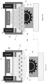
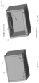
- FIGs 4a and 4b illustrate one example of a gas diffusion system 22.
- a front cover 50 is in place, while in Figure 4(b) it has been removed to show aspects of the interior of the gas diffusion system 22.
- gas diffusion system 22 is a rectilinear box having a UV light source 26, for example made up of one or more light emitting diodes (LEDs), mounted therein, inside a top of the box.
- a gas diffuser 30 forms a bottom face of the box.
- the gas diffuser is made of a transparent (at the wavelengths of illumination necessary for curing of the photocurable material used to fabricate the part under construction) material to allow UV light from source 26 to pass through relatively unattenuated.
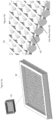
- FIGS 5a and 5b highlight the construction of diffuser 30.
- bridges 42 in the illustrated example, fashioned as ribs running longitudinally across an upper surface of the diffuser 30
- gas flow holes 38 are disposed above gas flow holes 38 so that they are in an optical path between the UV light source 26 and the gas flow holes when the diffuser and UV light source are assembled in the gas diffusion system 22. This ensures that across the entire curing area the UV light will pass through at least some thickness of the transparent material. This ensures better light homogeneity and more even curing of the photopolymer in UV curable layer 36.
- gas enters (e.g., by action of a pumping arrangement) the diffusion system 22 via one or more inlet holes 28 and exits through the diffuser 30.
- a gas pressure homogenizer (not shown in this view) is used to ensure constant pressure throughout the system.
- Figures 6a and 6b illustrate the cooperating operations employed in the printing and curing process.
- Printing of a next layer (6a-10) begins with the deposition of a layer of UV curable material on the print surface of an object under fabrication.
- gas is pumped 52 through the diffuser 30 via the gas inlets 28, as shown in the gas pressure curve in Figure 6a .
- the gas pressure increases to the level required for the curing process (6a-20) and purges the oxygen from a region 44 adjacent to the diffuser 30.
- the thickness (H) of this region grows over time, as shown in the oxygen free area thickness curve in Figure 6a , and is related to the gas pressure as it is forced through the diffuser.
- the device under fabrication is raised (if necessary) so that the layer of UV curable material disposed on the workpiece is within the oxygen-free region 44, and the UV source 26 of the UV curing system 20 is then activated (6a-30), as shown in the UV source curve in Figure 6a .
- This causes curing of at least a portion of the layer of UV curable material disposed on the workpiece in a region exposed to the UV light.
- the workpiece is repositioned for deposition of the next layer of UV curable material and the gas pressure reduced.
- the gas pressure is maintained at a sufficient level to keep the diffusion system 22 filled in order to reduce the time necessary for the next cycle of curing.
- Embodiment 1 A system for preventing oxygen inhibition of a light-initiated polymerization reaction at ambient conditions, said system including an ultraviolet (UV) light source, a UV curing space for accepting a workpiece having a layer of UV curable material, and means for purging oxygen from the UV curing space to facilitate, within the UV curing space, UV curing of the UV curable material at times when the UV light source emits light onto the layer of UV curable material.
- UV ultraviolet
- Embodiment 2 The system of embodiment 1, wherein the means for purging oxygen include a gas diffusion system for introducing an inert gas into a workspace between the UV light source and the layer of UV material of the workpiece, and a transparent cover separating the UV light source and the workspace, wherein the gas diffusion system and the transparent cover are arranged relative to one another so as to permit an inert gas flowing in from one or more gas inlets of the gas diffusion system to flow out through a diffuser towards the workspace.
- the means for purging oxygen include a gas diffusion system for introducing an inert gas into a workspace between the UV light source and the layer of UV material of the workpiece, and a transparent cover separating the UV light source and the workspace, wherein the gas diffusion system and the transparent cover are arranged relative to one another so as to permit an inert gas flowing in from one or more gas inlets of the gas diffusion system to flow out through a diffuser towards the workspace.
- Embodiment 3 The system of any of the preceding embodiments, wherein the diffuser has a plurality of micro-holes with bridges of a UV transparent material arranged over said micro-holes so as to be positioned between respective entrances to the micro-holes and the UV light source.
- Embodiment 4 The system of any of the preceding embodiments, further including a gas pressure homogenizer for ensuring a constant pressure throughout the system.
- Embodiment 5 The system of any of the preceding embodiments, wherein the diffuser is made of the UV-transparent material to allow UV light from the UV light source to pass through it.
- Embodiment 6 The system of any of the preceding embodiments, wherein the micro-holes are sized and spaced relative to one another so as to optimize gas distribution and UV light distribution throughout the workspace.
- Embodiment 7 The system of any of the preceding embodiments, wherein the micro-holes are spaced relative to one another in an array so that the gas is approximately evenly distributed throughout the workspace and sized equally so that UV light is approximately evenly distributed within the workspace.
- Embodiment 8 The system of any of the preceding embodiments, wherein the micro-holes are spaced relative to one another in an array so that the gas is approximately evenly distributed throughout the workspace and UV light is approximately evenly distributed within the workspace.
- Embodiment 9 The system of any of the preceding embodiments, wherein the temperature of the inert gas is controlled to create a uniform reaction temperature.
- Embodiment 10 The system of any of the preceding embodiments, wherein the inert gas is heated to maintain a desired and uniform reaction temperature.
- Embodiment 11 A method for preventing oxygen inhibition of a light-initiated polymerization reaction at ambient conditions, said method including periodically emitting an ultraviolet (UV) light from a UV light source into a UV curing space in which a workpiece having a layer of UV curable material is disposed to facilitate, within the UV curing space, UV curing of the UV curable material, and purging oxygen from the UV curing space at times when the UV light source emits light onto the layer of UV curable material.
- UV ultraviolet
- Embodiment 12 The method of embodiment 11, wherein purging oxygen from the UV curing space comprises introducing, via a gas diffusion system, an inert gas into a workspace between the UV light source and the layer of UV material of the workpiece.
- Embodiment 13 The method of either of embodiments 11 or 12, wherein the inert gas is introduced via one or more gas inlets of the gas diffusion system and through a plurality of micro-holes in a transparent diffuser separating the UV light source and the workspace towards the workspace.
- Embodiment 14 The method of any of embodiments 11-13, wherein the UV light from the UV light source is passed through bridges of a UV transparent material arranged over said micro-holes of said diffuser towards the layer of UV material of the workpiece.
- Embodiment 15 The method of any of embodiments 11-14, wherein the inert gas is approximately evenly distributed throughout the workspace via the micro-holes.
- Embodiment 16 The method of any of embodiments 11-15, wherein the UV light is approximately evenly distributed within the workspace via the micro-holes.
- Embodiment 17 The method of any of embodiments 11-16, wherein the inert gas temperature is controlled to create a uniform reaction temperature.
- Embodiment 18 The method of claim any of embodiments 11-17, wherein the inert gas is heated to maintain a desired and uniform reaction temperature.
- Embodiment 19 The method of any of embodiment 11, wherein purging oxygen from the UV curing space comprises during deposition of the layer of UV curable material onto the workpiece, introducing an inert gas through a diffuser into the UV curing space within which the workpiece is located, said inert gas being introduced to a pressure sufficient to purge oxygen from a region adjacent to the diffuser.
- Embodiment 20 The method of either of embodiments 11 or 19, further comprising after curing of the layer of UV curable material, repositioning the workpiece for deposition of a next layer of UV curable material and reducing the inert gas pressure in the region adjacent to the diffuser.
Landscapes
- Engineering & Computer Science (AREA)
- Chemical & Material Sciences (AREA)
- Materials Engineering (AREA)
- Physics & Mathematics (AREA)
- Health & Medical Sciences (AREA)
- Manufacturing & Machinery (AREA)
- Mechanical Engineering (AREA)
- Optics & Photonics (AREA)
- Toxicology (AREA)
- Thermal Sciences (AREA)
- Oral & Maxillofacial Surgery (AREA)
- Environmental & Geological Engineering (AREA)
- Electromagnetism (AREA)
- General Health & Medical Sciences (AREA)
- Analytical Chemistry (AREA)
- Life Sciences & Earth Sciences (AREA)
- Biochemistry (AREA)
- Pathology (AREA)
- General Physics & Mathematics (AREA)
- Immunology (AREA)
- Heating, Cooling, Or Curing Plastics Or The Like In General (AREA)
- Processes Of Treating Macromolecular Substances (AREA)
- Application Of Or Painting With Fluid Materials (AREA)
Applications Claiming Priority (3)
| Application Number | Priority Date | Filing Date | Title |
|---|---|---|---|
| US201862777902P | 2018-12-11 | 2018-12-11 | |
| EP19832728.0A EP3894181B1 (de) | 2018-12-11 | 2019-12-04 | Systeme und verfahren zur verhinderung der sauerstoffinhibierung einer durch licht initiierten polymerisationsreaktion in einem 3d-drucksystem unter verwendung von inertgas |
| PCT/IB2019/060453 WO2020121132A1 (en) | 2018-12-11 | 2019-12-04 | Systems and methods for preventing oxygen inhibition of a light-initiated polymerization reaction in a 3d printing system using inert gas |
Related Parent Applications (2)
| Application Number | Title | Priority Date | Filing Date |
|---|---|---|---|
| EP19832728.0A Division EP3894181B1 (de) | 2018-12-11 | 2019-12-04 | Systeme und verfahren zur verhinderung der sauerstoffinhibierung einer durch licht initiierten polymerisationsreaktion in einem 3d-drucksystem unter verwendung von inertgas |
| EP19832728.0A Division-Into EP3894181B1 (de) | 2018-12-11 | 2019-12-04 | Systeme und verfahren zur verhinderung der sauerstoffinhibierung einer durch licht initiierten polymerisationsreaktion in einem 3d-drucksystem unter verwendung von inertgas |
Publications (3)
| Publication Number | Publication Date |
|---|---|
| EP4183554A1 true EP4183554A1 (de) | 2023-05-24 |
| EP4183554C0 EP4183554C0 (de) | 2024-10-02 |
| EP4183554B1 EP4183554B1 (de) | 2024-10-02 |
Family
ID=69143619
Family Applications (3)
| Application Number | Title | Priority Date | Filing Date |
|---|---|---|---|
| EP22196770.6A Active EP4183554B1 (de) | 2018-12-11 | 2019-12-04 | Verfahren zur verhinderung der sauerstoffhemmung einer lichtinitiierten polymerisationsreaktion in einem 3d-drucksystem mit inertgas |
| EP19832727.2A Active EP3894180B1 (de) | 2018-12-11 | 2019-12-04 | Systeme und verfahren zur verhinderung der sauerstoffhemmung einer durch licht initiierten polymerisierungsreaktion in einem 3d-drucksystem unter verwendung einheitlicher planarer oberflächen |
| EP19832728.0A Active EP3894181B1 (de) | 2018-12-11 | 2019-12-04 | Systeme und verfahren zur verhinderung der sauerstoffinhibierung einer durch licht initiierten polymerisationsreaktion in einem 3d-drucksystem unter verwendung von inertgas |
Family Applications After (2)
| Application Number | Title | Priority Date | Filing Date |
|---|---|---|---|
| EP19832727.2A Active EP3894180B1 (de) | 2018-12-11 | 2019-12-04 | Systeme und verfahren zur verhinderung der sauerstoffhemmung einer durch licht initiierten polymerisierungsreaktion in einem 3d-drucksystem unter verwendung einheitlicher planarer oberflächen |
| EP19832728.0A Active EP3894181B1 (de) | 2018-12-11 | 2019-12-04 | Systeme und verfahren zur verhinderung der sauerstoffinhibierung einer durch licht initiierten polymerisationsreaktion in einem 3d-drucksystem unter verwendung von inertgas |
Country Status (6)
| Country | Link |
|---|---|
| US (4) | US11453164B2 (de) |
| EP (3) | EP4183554B1 (de) |
| JP (2) | JP7471299B2 (de) |
| KR (2) | KR20210134304A (de) |
| CN (2) | CN113412186B (de) |
| WO (2) | WO2020121132A1 (de) |
Families Citing this family (2)
| Publication number | Priority date | Publication date | Assignee | Title |
|---|---|---|---|---|
| US11654618B2 (en) * | 2019-04-25 | 2023-05-23 | 3D Systems, Inc. | Three dimensional printing system with partially immersed imaging bar defining build plane below a free surface of photocurable resin |
| US12420479B2 (en) | 2021-12-23 | 2025-09-23 | Reophotonics, Ltd. | Systems for printing viscous materials using laser assisted deposition |
Citations (4)
| Publication number | Priority date | Publication date | Assignee | Title |
|---|---|---|---|---|
| EP0435564A2 (de) * | 1989-12-22 | 1991-07-03 | E.I. Du Pont De Nemours And Company | Raumbilderzeugungssystem für Festkörper |
| US5447822A (en) * | 1989-09-28 | 1995-09-05 | 3D Systems, Inc. | Apparatus and related method for forming a substantially flat stereolithographic working surface |
| US20100259589A1 (en) * | 2009-04-14 | 2010-10-14 | Jonathan Barry | Inert uv inkjet printing |
| US20180079004A1 (en) * | 2016-09-19 | 2018-03-22 | Cl Schutzrechtsverwaltungs Gmbh | Apparatus for manufacturing of three-dimensional objects |
Family Cites Families (23)
| Publication number | Priority date | Publication date | Assignee | Title |
|---|---|---|---|---|
| JPH02103128A (ja) * | 1988-10-13 | 1990-04-16 | Matsushita Electric Works Ltd | 三次元形状の形成方法 |
| GB2233928B (en) * | 1989-05-23 | 1992-12-23 | Brother Ind Ltd | Apparatus and method for forming three-dimensional article |
| JP2665258B2 (ja) * | 1989-07-24 | 1997-10-22 | 松下電工株式会社 | 三次元形状の形成方法 |
| US5122441A (en) * | 1990-10-29 | 1992-06-16 | E. I. Du Pont De Nemours And Company | Method for fabricating an integral three-dimensional object from layers of a photoformable composition |
| CN1131741A (zh) * | 1995-03-22 | 1996-09-25 | 载歌公司 | 光学间隙测量装置和方法 |
| JP4033987B2 (ja) | 1998-11-19 | 2008-01-16 | ナブテスコ株式会社 | 光学的立体造形方法 |
| JP2000318050A (ja) | 1999-05-11 | 2000-11-21 | Sanyo Electric Co Ltd | 光造形装置及び光造形方法 |
| JP5364439B2 (ja) | 2009-05-15 | 2013-12-11 | パナソニック株式会社 | 三次元形状造形物の製造方法 |
| CN103109357B (zh) | 2010-10-19 | 2016-08-24 | 应用材料公司 | 用于紫外线纳米固化腔室的石英喷洒器 |
| CA2847351C (en) * | 2011-09-23 | 2017-02-21 | Stratasys, Inc. | Layer transfusion for additive manufacturing |
| DE102011085154A1 (de) * | 2011-10-25 | 2013-04-25 | Evonik Industries Ag | Vorrichtung zur Vermeidung von Ablagerungen an optischen Komponenten im Laser-Sintern |
| WO2014054749A1 (ja) * | 2012-10-04 | 2014-04-10 | 大日本印刷株式会社 | インプリント方法およびインプリント装置 |
| TWI561401B (en) * | 2014-04-29 | 2016-12-11 | Xyzprinting Inc | Three dimensional printing apparatus |
| US10160194B2 (en) * | 2015-03-03 | 2018-12-25 | Xerox Corporation | Systems and methods for implementing high speed final surface curing for three dimensional (3D) printed parts and components |
| EP3147047B1 (de) | 2015-09-25 | 2023-08-02 | SLM Solutions Group AG | Vorrichtung zur herstellung eines dreidimensionalen werkstücks mit verbesserter gasströmung und herstellungsverfahren eines dreidimensionalen werkstücks |
| CN205467381U (zh) * | 2016-01-13 | 2016-08-17 | 中国科学院福建物质结构研究所 | 一种3d打印设备 |
| JP6095147B1 (ja) | 2016-07-13 | 2017-03-15 | 株式会社ソディック | 積層造形装置 |
| DE102016216678A1 (de) | 2016-09-02 | 2018-03-08 | Eos Gmbh Electro Optical Systems | Verfahren und Vorrichtung zum generativen Herstellen eines dreidimensionalen Objekts |
| DE102016216682A1 (de) | 2016-09-02 | 2018-03-08 | Eos Gmbh Electro Optical Systems | Verfahren und Vorrichtung zum generativen Herstellen eines dreidimensionalen Objekts |
| JP6866152B2 (ja) | 2016-12-22 | 2021-04-28 | キヤノン株式会社 | 三次元造形装置および三次元造形方法 |
| CN206551490U (zh) * | 2016-12-16 | 2017-10-13 | 北京隆源自动成型系统有限公司 | 带有激光加热的3d打印机 |
| WO2019168611A1 (en) * | 2018-03-01 | 2019-09-06 | NEXA3D Inc. | Method and system for measuring a pressure distribution between a surface of an object and a pressure sensitive surface during formation of the object |
| US10809205B2 (en) * | 2018-07-27 | 2020-10-20 | Intrepid Automation | Detection of 3D printing failure using imaging |
-
2019
- 2019-12-04 KR KR1020217018464A patent/KR20210134304A/ko active Pending
- 2019-12-04 KR KR1020217018439A patent/KR20210132640A/ko active Pending
- 2019-12-04 JP JP2021533301A patent/JP7471299B2/ja active Active
- 2019-12-04 EP EP22196770.6A patent/EP4183554B1/de active Active
- 2019-12-04 JP JP2021533302A patent/JP7476197B2/ja active Active
- 2019-12-04 US US16/703,423 patent/US11453164B2/en active Active
- 2019-12-04 WO PCT/IB2019/060453 patent/WO2020121132A1/en not_active Ceased
- 2019-12-04 CN CN201980082395.5A patent/CN113412186B/zh active Active
- 2019-12-04 EP EP19832727.2A patent/EP3894180B1/de active Active
- 2019-12-04 WO PCT/IB2019/060451 patent/WO2020121131A1/en not_active Ceased
- 2019-12-04 EP EP19832728.0A patent/EP3894181B1/de active Active
- 2019-12-04 CN CN201980082465.7A patent/CN113365796B/zh active Active
- 2019-12-04 US US16/703,417 patent/US11203154B2/en active Active
-
2021
- 2021-11-02 US US17/453,292 patent/US11673328B2/en active Active
-
2022
- 2022-08-11 US US17/819,279 patent/US11590701B2/en active Active
Patent Citations (4)
| Publication number | Priority date | Publication date | Assignee | Title |
|---|---|---|---|---|
| US5447822A (en) * | 1989-09-28 | 1995-09-05 | 3D Systems, Inc. | Apparatus and related method for forming a substantially flat stereolithographic working surface |
| EP0435564A2 (de) * | 1989-12-22 | 1991-07-03 | E.I. Du Pont De Nemours And Company | Raumbilderzeugungssystem für Festkörper |
| US20100259589A1 (en) * | 2009-04-14 | 2010-10-14 | Jonathan Barry | Inert uv inkjet printing |
| US20180079004A1 (en) * | 2016-09-19 | 2018-03-22 | Cl Schutzrechtsverwaltungs Gmbh | Apparatus for manufacturing of three-dimensional objects |
Also Published As
| Publication number | Publication date |
|---|---|
| EP3894180A1 (de) | 2021-10-20 |
| EP3894181A1 (de) | 2021-10-20 |
| JP7471299B2 (ja) | 2024-04-19 |
| KR20210134304A (ko) | 2021-11-09 |
| JP2022512225A (ja) | 2022-02-02 |
| CN113412186B (zh) | 2023-04-04 |
| CN113365796A (zh) | 2021-09-07 |
| US20220055302A1 (en) | 2022-02-24 |
| US20200180225A1 (en) | 2020-06-11 |
| US11203154B2 (en) | 2021-12-21 |
| US11453164B2 (en) | 2022-09-27 |
| US11590701B2 (en) | 2023-02-28 |
| WO2020121132A1 (en) | 2020-06-18 |
| EP3894181B1 (de) | 2022-11-16 |
| JP2022512224A (ja) | 2022-02-02 |
| EP3894180C0 (de) | 2023-11-01 |
| EP4183554C0 (de) | 2024-10-02 |
| JP7476197B2 (ja) | 2024-04-30 |
| US11673328B2 (en) | 2023-06-13 |
| US20200180190A1 (en) | 2020-06-11 |
| CN113412186A (zh) | 2021-09-17 |
| CN113365796B (zh) | 2023-03-21 |
| EP3894180B1 (de) | 2023-11-01 |
| EP4183554B1 (de) | 2024-10-02 |
| WO2020121131A1 (en) | 2020-06-18 |
| US20220379560A1 (en) | 2022-12-01 |
| KR20210132640A (ko) | 2021-11-04 |
Similar Documents
| Publication | Publication Date | Title |
|---|---|---|
| US11673328B2 (en) | Methods for preventing oxygen inhibition of a light-initiated polymerization reaction in a 3D printing system using inert gas | |
| US10267563B2 (en) | System, method, and adjustable lamp head assembly, for ultra-fast UV curing | |
| EP1804243B1 (de) | Lichteffekte mit mehreren Attributen zur Verwendung in Härtungsverfahren und in anderen Anwendungen unter Verwendung von Photoreaktionen | |
| JP2013505354A (ja) | 基板上にポリマーフィルムを化学気相蒸着するための方法およびデバイス | |
| JP6723351B2 (ja) | 細長状物を被覆するための方法、ケーブル、該方法のための装置、該装置の制御方法およびコンピュータプログラム製品 | |
| RU2266265C2 (ru) | Способ вытягивания оптического волокна | |
| KR20180075122A (ko) | 기재 타입의 양면테이프의 제조장치 및 제조방법 | |
| TWI758683B (zh) | 成膜裝置 | |
| JP4937441B2 (ja) | ファイバ上に設けられる光硬化可能コーティングを硬化するための装置および方法 | |
| JP7250599B2 (ja) | 成膜装置及び成膜方法 | |
| KR102431725B1 (ko) | 잉크젯 프린팅 시스템 용 자외선 경화장치 | |
| CN219055035U (zh) | 一种应用于光固化膜的金属网调光装置 | |
| KR102783465B1 (ko) | 광섬유 코팅장치 및 이를 이용한 광섬유 코팅방법 | |
| JP4172062B2 (ja) | 線状体に紫外線硬化樹脂を被覆する方法 | |
| US11478986B2 (en) | Reactor for prepolymerization of a photopolymerizable material | |
| JPWO2020121132A5 (de) | ||
| DE102012015140A1 (de) | Verfahren zur kontinuierlichen Herstellung eines Wellenleiterbündels aus mit optischer Strahlung aushärtenden, optisch transparenten Materialien | |
| KR101570577B1 (ko) | 모노머 증착 장치 | |
| EP4414393A1 (de) | Härtbare zusammensetzung, gehärtetes produkt, verfahren zur herstellung eines gehärteten produkts und vorrichtung zur herstellung eines gehärteten produkts | |
| DE102007053543B4 (de) | Vorrichtung zur Bestrahlung von Elementen mit UV-Licht sowie Verfahren zu deren Betrieb | |
| JP2025128884A (ja) | 硬化性樹脂の改質方法及び硬化方法、並びに、硬化性樹脂のプレキュア装置、改質処理システム及び硬化処理システム | |
| WO2025192343A1 (ja) | ミストを用いた活性種の供給方法及び成膜装置 | |
| JPS6395143A (ja) | 光フアイバ被覆架橋装置 | |
| JP2014198282A (ja) | 塗布膜付き支持体の製造方法 | |
| KR20160042267A (ko) | 모노머 진공 증착 장치 |
Legal Events
| Date | Code | Title | Description |
|---|---|---|---|
| PUAI | Public reference made under article 153(3) epc to a published international application that has entered the european phase |
Free format text: ORIGINAL CODE: 0009012 |
|
| STAA | Information on the status of an ep patent application or granted ep patent |
Free format text: STATUS: THE APPLICATION HAS BEEN PUBLISHED |
|
| AC | Divisional application: reference to earlier application |
Ref document number: 3894181 Country of ref document: EP Kind code of ref document: P |
|
| AK | Designated contracting states |
Kind code of ref document: A1 Designated state(s): AL AT BE BG CH CY CZ DE DK EE ES FI FR GB GR HR HU IE IS IT LI LT LU LV MC MK MT NL NO PL PT RO RS SE SI SK SM TR |
|
| STAA | Information on the status of an ep patent application or granted ep patent |
Free format text: STATUS: REQUEST FOR EXAMINATION WAS MADE |
|
| 17P | Request for examination filed |
Effective date: 20231123 |
|
| RBV | Designated contracting states (corrected) |
Designated state(s): AL AT BE BG CH CY CZ DE DK EE ES FI FR GB GR HR HU IE IS IT LI LT LU LV MC MK MT NL NO PL PT RO RS SE SI SK SM TR |
|
| GRAP | Despatch of communication of intention to grant a patent |
Free format text: ORIGINAL CODE: EPIDOSNIGR1 |
|
| STAA | Information on the status of an ep patent application or granted ep patent |
Free format text: STATUS: GRANT OF PATENT IS INTENDED |
|
| INTG | Intention to grant announced |
Effective date: 20240510 |
|
| RAP3 | Party data changed (applicant data changed or rights of an application transferred) |
Owner name: IO TECH GROUP, LTD. |
|
| GRAS | Grant fee paid |
Free format text: ORIGINAL CODE: EPIDOSNIGR3 |
|
| GRAA | (expected) grant |
Free format text: ORIGINAL CODE: 0009210 |
|
| STAA | Information on the status of an ep patent application or granted ep patent |
Free format text: STATUS: THE PATENT HAS BEEN GRANTED |
|
| AC | Divisional application: reference to earlier application |
Ref document number: 3894181 Country of ref document: EP Kind code of ref document: P |
|
| AK | Designated contracting states |
Kind code of ref document: B1 Designated state(s): AL AT BE BG CH CY CZ DE DK EE ES FI FR GB GR HR HU IE IS IT LI LT LU LV MC MK MT NL NO PL PT RO RS SE SI SK SM TR |
|
| REG | Reference to a national code |
Ref country code: GB Ref legal event code: FG4D |
|
| REG | Reference to a national code |
Ref country code: CH Ref legal event code: EP |
|
| REG | Reference to a national code |
Ref country code: IE Ref legal event code: FG4D |
|
| REG | Reference to a national code |
Ref country code: DE Ref legal event code: R096 Ref document number: 602019059909 Country of ref document: DE |
|
| U01 | Request for unitary effect filed |
Effective date: 20241009 |
|
| U07 | Unitary effect registered |
Designated state(s): AT BE BG DE DK EE FI FR IT LT LU LV MT NL PT RO SE SI Effective date: 20241029 |
|
| U20 | Renewal fee for the european patent with unitary effect paid |
Year of fee payment: 6 Effective date: 20241227 |
|
| PG25 | Lapsed in a contracting state [announced via postgrant information from national office to epo] |
Ref country code: IS Free format text: LAPSE BECAUSE OF FAILURE TO SUBMIT A TRANSLATION OF THE DESCRIPTION OR TO PAY THE FEE WITHIN THE PRESCRIBED TIME-LIMIT Effective date: 20250202 Ref country code: HR Free format text: LAPSE BECAUSE OF FAILURE TO SUBMIT A TRANSLATION OF THE DESCRIPTION OR TO PAY THE FEE WITHIN THE PRESCRIBED TIME-LIMIT Effective date: 20241002 |
|
| PG25 | Lapsed in a contracting state [announced via postgrant information from national office to epo] |
Ref country code: ES Free format text: LAPSE BECAUSE OF FAILURE TO SUBMIT A TRANSLATION OF THE DESCRIPTION OR TO PAY THE FEE WITHIN THE PRESCRIBED TIME-LIMIT Effective date: 20241002 |
|
| PG25 | Lapsed in a contracting state [announced via postgrant information from national office to epo] |
Ref country code: NO Free format text: LAPSE BECAUSE OF FAILURE TO SUBMIT A TRANSLATION OF THE DESCRIPTION OR TO PAY THE FEE WITHIN THE PRESCRIBED TIME-LIMIT Effective date: 20250102 |
|
| PG25 | Lapsed in a contracting state [announced via postgrant information from national office to epo] |
Ref country code: GR Free format text: LAPSE BECAUSE OF FAILURE TO SUBMIT A TRANSLATION OF THE DESCRIPTION OR TO PAY THE FEE WITHIN THE PRESCRIBED TIME-LIMIT Effective date: 20250103 |
|
| PG25 | Lapsed in a contracting state [announced via postgrant information from national office to epo] |
Ref country code: CZ Free format text: LAPSE BECAUSE OF FAILURE TO SUBMIT A TRANSLATION OF THE DESCRIPTION OR TO PAY THE FEE WITHIN THE PRESCRIBED TIME-LIMIT Effective date: 20241002 Ref country code: PL Free format text: LAPSE BECAUSE OF FAILURE TO SUBMIT A TRANSLATION OF THE DESCRIPTION OR TO PAY THE FEE WITHIN THE PRESCRIBED TIME-LIMIT Effective date: 20241002 |
|
| PG25 | Lapsed in a contracting state [announced via postgrant information from national office to epo] |
Ref country code: RS Free format text: LAPSE BECAUSE OF FAILURE TO SUBMIT A TRANSLATION OF THE DESCRIPTION OR TO PAY THE FEE WITHIN THE PRESCRIBED TIME-LIMIT Effective date: 20250102 |
|
| PG25 | Lapsed in a contracting state [announced via postgrant information from national office to epo] |
Ref country code: SM Free format text: LAPSE BECAUSE OF FAILURE TO SUBMIT A TRANSLATION OF THE DESCRIPTION OR TO PAY THE FEE WITHIN THE PRESCRIBED TIME-LIMIT Effective date: 20241002 |
|
| PG25 | Lapsed in a contracting state [announced via postgrant information from national office to epo] |
Ref country code: MC Free format text: LAPSE BECAUSE OF FAILURE TO SUBMIT A TRANSLATION OF THE DESCRIPTION OR TO PAY THE FEE WITHIN THE PRESCRIBED TIME-LIMIT Effective date: 20241002 |
|
| PG25 | Lapsed in a contracting state [announced via postgrant information from national office to epo] |
Ref country code: SK Free format text: LAPSE BECAUSE OF FAILURE TO SUBMIT A TRANSLATION OF THE DESCRIPTION OR TO PAY THE FEE WITHIN THE PRESCRIBED TIME-LIMIT Effective date: 20241002 |
|
| REG | Reference to a national code |
Ref country code: CH Ref legal event code: PL |
|
| PLBE | No opposition filed within time limit |
Free format text: ORIGINAL CODE: 0009261 |
|
| STAA | Information on the status of an ep patent application or granted ep patent |
Free format text: STATUS: NO OPPOSITION FILED WITHIN TIME LIMIT |
|
| 26N | No opposition filed |
Effective date: 20250703 |
|
| GBPC | Gb: european patent ceased through non-payment of renewal fee |
Effective date: 20250102 |
|
| PG25 | Lapsed in a contracting state [announced via postgrant information from national office to epo] |
Ref country code: GB Free format text: LAPSE BECAUSE OF NON-PAYMENT OF DUE FEES Effective date: 20250102 |
|
| PG25 | Lapsed in a contracting state [announced via postgrant information from national office to epo] |
Ref country code: CH Free format text: LAPSE BECAUSE OF NON-PAYMENT OF DUE FEES Effective date: 20241231 |
|
| PG25 | Lapsed in a contracting state [announced via postgrant information from national office to epo] |
Ref country code: IE Free format text: LAPSE BECAUSE OF NON-PAYMENT OF DUE FEES Effective date: 20241204 |
|
| U20 | Renewal fee for the european patent with unitary effect paid |
Year of fee payment: 7 Effective date: 20251229 |
|
| PG25 | Lapsed in a contracting state [announced via postgrant information from national office to epo] |
Ref country code: CY Free format text: LAPSE BECAUSE OF FAILURE TO SUBMIT A TRANSLATION OF THE DESCRIPTION OR TO PAY THE FEE WITHIN THE PRESCRIBED TIME-LIMIT; INVALID AB INITIO Effective date: 20191204 |