EP4173899A1 - Composant de garniture de véhicule et un procédé de fabrication d'un tel composant de garniture - Google Patents
Composant de garniture de véhicule et un procédé de fabrication d'un tel composant de garniture Download PDFInfo
- Publication number
- EP4173899A1 EP4173899A1 EP22203742.6A EP22203742A EP4173899A1 EP 4173899 A1 EP4173899 A1 EP 4173899A1 EP 22203742 A EP22203742 A EP 22203742A EP 4173899 A1 EP4173899 A1 EP 4173899A1
- Authority
- EP
- European Patent Office
- Prior art keywords
- support panel
- channel
- reinforcing frame
- trim component
- peripheral edge
- Prior art date
- Legal status (The legal status is an assumption and is not a legal conclusion. Google has not performed a legal analysis and makes no representation as to the accuracy of the status listed.)
- Granted
Links
Images

Classifications
-
- B—PERFORMING OPERATIONS; TRANSPORTING
- B60—VEHICLES IN GENERAL
- B60R—VEHICLES, VEHICLE FITTINGS, OR VEHICLE PARTS, NOT OTHERWISE PROVIDED FOR
- B60R21/00—Arrangements or fittings on vehicles for protecting or preventing injuries to occupants or pedestrians in case of accidents or other traffic risks
- B60R21/02—Occupant safety arrangements or fittings, e.g. crash pads
- B60R21/16—Inflatable occupant restraints or confinements designed to inflate upon impact or impending impact, e.g. air bags
- B60R21/20—Arrangements for storing inflatable members in their non-use or deflated condition; Arrangement or mounting of air bag modules or components
- B60R21/215—Arrangements for storing inflatable members in their non-use or deflated condition; Arrangement or mounting of air bag modules or components characterised by the covers for the inflatable member
-
- B—PERFORMING OPERATIONS; TRANSPORTING
- B29—WORKING OF PLASTICS; WORKING OF SUBSTANCES IN A PLASTIC STATE IN GENERAL
- B29C—SHAPING OR JOINING OF PLASTICS; SHAPING OF MATERIAL IN A PLASTIC STATE, NOT OTHERWISE PROVIDED FOR; AFTER-TREATMENT OF THE SHAPED PRODUCTS, e.g. REPAIRING
- B29C43/00—Compression moulding, i.e. applying external pressure to flow the moulding material; Apparatus therefor
- B29C43/003—Compression moulding, i.e. applying external pressure to flow the moulding material; Apparatus therefor characterised by the choice of material
-
- B—PERFORMING OPERATIONS; TRANSPORTING
- B29—WORKING OF PLASTICS; WORKING OF SUBSTANCES IN A PLASTIC STATE IN GENERAL
- B29C—SHAPING OR JOINING OF PLASTICS; SHAPING OF MATERIAL IN A PLASTIC STATE, NOT OTHERWISE PROVIDED FOR; AFTER-TREATMENT OF THE SHAPED PRODUCTS, e.g. REPAIRING
- B29C43/00—Compression moulding, i.e. applying external pressure to flow the moulding material; Apparatus therefor
- B29C43/02—Compression moulding, i.e. applying external pressure to flow the moulding material; Apparatus therefor of articles of definite length, i.e. discrete articles
- B29C43/18—Compression moulding, i.e. applying external pressure to flow the moulding material; Apparatus therefor of articles of definite length, i.e. discrete articles incorporating preformed parts or layers, e.g. compression moulding around inserts or for coating articles
-
- B—PERFORMING OPERATIONS; TRANSPORTING
- B60—VEHICLES IN GENERAL
- B60R—VEHICLES, VEHICLE FITTINGS, OR VEHICLE PARTS, NOT OTHERWISE PROVIDED FOR
- B60R13/00—Elements for body-finishing, identifying, or decorating; Arrangements or adaptations for advertising purposes
- B60R13/02—Internal Trim mouldings ; Internal Ledges; Wall liners for passenger compartments; Roof liners
-
- B—PERFORMING OPERATIONS; TRANSPORTING
- B60—VEHICLES IN GENERAL
- B60R—VEHICLES, VEHICLE FITTINGS, OR VEHICLE PARTS, NOT OTHERWISE PROVIDED FOR
- B60R21/00—Arrangements or fittings on vehicles for protecting or preventing injuries to occupants or pedestrians in case of accidents or other traffic risks
- B60R21/02—Occupant safety arrangements or fittings, e.g. crash pads
- B60R21/16—Inflatable occupant restraints or confinements designed to inflate upon impact or impending impact, e.g. air bags
- B60R21/20—Arrangements for storing inflatable members in their non-use or deflated condition; Arrangement or mounting of air bag modules or components
- B60R21/205—Arrangements for storing inflatable members in their non-use or deflated condition; Arrangement or mounting of air bag modules or components in dashboards
-
- B—PERFORMING OPERATIONS; TRANSPORTING
- B60—VEHICLES IN GENERAL
- B60R—VEHICLES, VEHICLE FITTINGS, OR VEHICLE PARTS, NOT OTHERWISE PROVIDED FOR
- B60R21/00—Arrangements or fittings on vehicles for protecting or preventing injuries to occupants or pedestrians in case of accidents or other traffic risks
- B60R21/02—Occupant safety arrangements or fittings, e.g. crash pads
- B60R21/16—Inflatable occupant restraints or confinements designed to inflate upon impact or impending impact, e.g. air bags
- B60R21/20—Arrangements for storing inflatable members in their non-use or deflated condition; Arrangement or mounting of air bag modules or components
- B60R21/215—Arrangements for storing inflatable members in their non-use or deflated condition; Arrangement or mounting of air bag modules or components characterised by the covers for the inflatable member
- B60R21/2165—Arrangements for storing inflatable members in their non-use or deflated condition; Arrangement or mounting of air bag modules or components characterised by the covers for the inflatable member characterised by a tear line for defining a deployment opening
-
- B—PERFORMING OPERATIONS; TRANSPORTING
- B60—VEHICLES IN GENERAL
- B60R—VEHICLES, VEHICLE FITTINGS, OR VEHICLE PARTS, NOT OTHERWISE PROVIDED FOR
- B60R21/00—Arrangements or fittings on vehicles for protecting or preventing injuries to occupants or pedestrians in case of accidents or other traffic risks
- B60R21/02—Occupant safety arrangements or fittings, e.g. crash pads
- B60R21/16—Inflatable occupant restraints or confinements designed to inflate upon impact or impending impact, e.g. air bags
- B60R21/20—Arrangements for storing inflatable members in their non-use or deflated condition; Arrangement or mounting of air bag modules or components
- B60R21/217—Inflation fluid source retainers, e.g. reaction canisters; Connection of bags, covers, diffusers or inflation fluid sources therewith or together
-
- B—PERFORMING OPERATIONS; TRANSPORTING
- B29—WORKING OF PLASTICS; WORKING OF SUBSTANCES IN A PLASTIC STATE IN GENERAL
- B29K—INDEXING SCHEME ASSOCIATED WITH SUBCLASSES B29B, B29C OR B29D, RELATING TO MOULDING MATERIALS OR TO MATERIALS FOR MOULDS, REINFORCEMENTS, FILLERS OR PREFORMED PARTS, e.g. INSERTS
- B29K2105/00—Condition, form or state of moulded material or of the material to be shaped
- B29K2105/06—Condition, form or state of moulded material or of the material to be shaped containing reinforcements, fillers or inserts
- B29K2105/12—Condition, form or state of moulded material or of the material to be shaped containing reinforcements, fillers or inserts of short lengths, e.g. chopped filaments, staple fibres or bristles
-
- B—PERFORMING OPERATIONS; TRANSPORTING
- B29—WORKING OF PLASTICS; WORKING OF SUBSTANCES IN A PLASTIC STATE IN GENERAL
- B29K—INDEXING SCHEME ASSOCIATED WITH SUBCLASSES B29B, B29C OR B29D, RELATING TO MOULDING MATERIALS OR TO MATERIALS FOR MOULDS, REINFORCEMENTS, FILLERS OR PREFORMED PARTS, e.g. INSERTS
- B29K2311/00—Use of natural products or their composites, not provided for in groups B29K2201/00 - B29K2309/00, as reinforcement
-
- B—PERFORMING OPERATIONS; TRANSPORTING
- B29—WORKING OF PLASTICS; WORKING OF SUBSTANCES IN A PLASTIC STATE IN GENERAL
- B29K—INDEXING SCHEME ASSOCIATED WITH SUBCLASSES B29B, B29C OR B29D, RELATING TO MOULDING MATERIALS OR TO MATERIALS FOR MOULDS, REINFORCEMENTS, FILLERS OR PREFORMED PARTS, e.g. INSERTS
- B29K2311/00—Use of natural products or their composites, not provided for in groups B29K2201/00 - B29K2309/00, as reinforcement
- B29K2311/10—Natural fibres, e.g. wool or cotton
-
- B—PERFORMING OPERATIONS; TRANSPORTING
- B29—WORKING OF PLASTICS; WORKING OF SUBSTANCES IN A PLASTIC STATE IN GENERAL
- B29K—INDEXING SCHEME ASSOCIATED WITH SUBCLASSES B29B, B29C OR B29D, RELATING TO MOULDING MATERIALS OR TO MATERIALS FOR MOULDS, REINFORCEMENTS, FILLERS OR PREFORMED PARTS, e.g. INSERTS
- B29K2311/00—Use of natural products or their composites, not provided for in groups B29K2201/00 - B29K2309/00, as reinforcement
- B29K2311/14—Wood, e.g. woodboard or fibreboard
-
- B—PERFORMING OPERATIONS; TRANSPORTING
- B29—WORKING OF PLASTICS; WORKING OF SUBSTANCES IN A PLASTIC STATE IN GENERAL
- B29L—INDEXING SCHEME ASSOCIATED WITH SUBCLASS B29C, RELATING TO PARTICULAR ARTICLES
- B29L2031/00—Other particular articles
- B29L2031/30—Vehicles, e.g. ships or aircraft, or body parts thereof
- B29L2031/3005—Body finishings
- B29L2031/3038—Air bag covers
-
- B—PERFORMING OPERATIONS; TRANSPORTING
- B60—VEHICLES IN GENERAL
- B60R—VEHICLES, VEHICLE FITTINGS, OR VEHICLE PARTS, NOT OTHERWISE PROVIDED FOR
- B60R13/00—Elements for body-finishing, identifying, or decorating; Arrangements or adaptations for advertising purposes
- B60R13/02—Internal Trim mouldings ; Internal Ledges; Wall liners for passenger compartments; Roof liners
- B60R2013/0287—Internal Trim mouldings ; Internal Ledges; Wall liners for passenger compartments; Roof liners integrating other functions or accessories
-
- B—PERFORMING OPERATIONS; TRANSPORTING
- B60—VEHICLES IN GENERAL
- B60R—VEHICLES, VEHICLE FITTINGS, OR VEHICLE PARTS, NOT OTHERWISE PROVIDED FOR
- B60R21/00—Arrangements or fittings on vehicles for protecting or preventing injuries to occupants or pedestrians in case of accidents or other traffic risks
- B60R21/02—Occupant safety arrangements or fittings, e.g. crash pads
- B60R21/16—Inflatable occupant restraints or confinements designed to inflate upon impact or impending impact, e.g. air bags
- B60R21/20—Arrangements for storing inflatable members in their non-use or deflated condition; Arrangement or mounting of air bag modules or components
- B60R21/217—Inflation fluid source retainers, e.g. reaction canisters; Connection of bags, covers, diffusers or inflation fluid sources therewith or together
- B60R2021/2172—Inflation fluid source retainers, e.g. reaction canisters; Connection of bags, covers, diffusers or inflation fluid sources therewith or together the cover being connected to the surrounding part and to the module, e.g. floating mounts
Definitions
- the invention relates to a trim or trim component for a vehicle, in particular for a motor vehicle.
- the invention also relates to a method of manufacturing such a packing component.
- trim components such as, for example, the dashboard are made from a support panel comprising natural fibers. It is necessary to attach airbag guide pieces to these support panels to meet safety requirements. However, in some panels, the guide piece is not firmly fixed. In other panels, the interface between the guide piece and the support panel is not planar.
- a first object of the invention is to firmly attach an airbag guide piece to a fiber support panel.
- a second object of the invention is to fix a cushion guide part inflatable to a support panel maintaining a flat interface between the guide piece and the support panel.
- a third object of the invention is to fix an airbag guide piece to a support panel at a precise position of the support panel.
- the channel is provided with at least one locking element capable of blocking the reinforcing frame in abutment against the peripheral edge of the support panel.
- the at least one locking element comprises a snap-fit fixing lug.
- the reinforcement frame comprises a ring extending in a plane parallel to the collar, and a skirt extending perpendicular to the ring and enclosing the channel.
- the at least one locking element bears against a free end of the skirt.
- the ring is adapted to press the peripheral edge of the support panel against the flange, the ring comprising an outer edge and a central opening delimiting an inner edge, and in which the dimension of the ring defined between the inner edge and the outer edge is between 5 millimeters and 50 millimeters and is preferably between 10 millimeters and 30 millimeters.
- the periphery of the channel comprises ribs extending in an axial direction; the reinforcing frame extending at least partially against the ribs.
- the reinforcing frame holds the peripheral edge of the support panel against the flange.
- the channel of the guide part is provided with at least one locking element, and in which said at least one locking element deforms reversibly during insertion of the channel of the part guide in the opening of the support panel and in the reinforcement frame then resumes its initial shape to block the reinforcement frame in abutment against a peripheral edge of the support panel.
- top the terms “top”, “bottom”, “lower” and “upper” are defined when the trim component according to the invention is arranged as illustrated in figure 1 , and are in no way limiting.
- the vehicle trim component 2 comprises a support panel 4, an airbag guide piece 6, a decorative covering 7 fixed to the support panel and to a part of the guide piece 6 and a reinforcement frame 8 fixed under the support panel.
- Trim component 2 is for example a vehicle dashboard or part of a vehicle dashboard. Alternatively, the trim component 2 is a vehicle center console or a vehicle door panel.
- the support panel 4 gives its geometric shape to the trim component 2.
- the heat-compressed support panel 4 has a thickness of 1.4 millimeters to 2.5 millimeters.
- the support panel 4, the guide piece 6 and the reinforcement frame 8 are fixed to each other by hot pressing.
- the support panel 4 is provided with a through opening 10 and a peripheral edge 12 surrounding the opening.
- the support panel 4 is made by thermocompression.
- the support panel 4 is made by hot pressing.
- the support panel 4 comprises fibers.
- the support panel 4 comprises for example natural fibers and a thermoplastic material.
- the natural fibers are, for example, hemp, wood, flax, kenaf and/or sisal fibers, preferably wood fibers.
- the thermoplastic material is for example polypropylene (PP) and/or polyethylene terephthalate (PET), preferably polypropylene (PP).
- PET polyethylene terephthalate
- the support panel 4 is presented, before the thermocompression step, in the form of a non-woven mat comprising intermingled fibers.
- the nonwoven mat comprises interwoven natural fibers and thermoplastic fibers.
- the nonwoven mat is for example formed by needling the fibers.
- the nonwoven mat has a thickness of 8 millimeters to 14 millimeters before the thermocompression step.
- the airbag guide piece 6 comprises a channel 14, a flap 16 at least partially closing a first end 14A of the channel 14 and a collar 18 arranged around the channel in the extension of the flap 16.
- the second end of the channel, opposite at the first end 14A, is referenced 14B.
- the guide piece 6 comprises several flaps 16 closing at least in part the first end of the channel 14, for example two flaps 16, as represented on the figure 1 .
- the guide piece 6 is preferably made in one piece by molding, for example by injection molding, of a plastic material.
- the channel 14 is arranged in the opening 10 of the support panel 4. It is generally called the firing channel.
- the channel 14 delimits an internal passage for the deployment of the airbag in the passenger compartment of the vehicle.
- the internal passage of channel 14 is opposed to an external contour of channel 14.
- the channel 14 is capable of guiding an airbag, when the latter deploys.
- Channel 14 has a tubular shape.
- the channel 14 has, for example, a cross section of rectangular shape.
- the channel 14 comprises for example four opposite walls two by two.
- Channel 14 extends around an A-A axis.
- the channel 14 extends from the first end 14A of the channel 14 to the second end 14B of the channel 14.
- the channel comprises in the vicinity of the second end 14B of the channel 14, in other words in its lower part, slots 20 in which a housing 22 is crocheted.
- the housing 22 is also fixed to the channel 14 by fixing means not shown.
- Housing 22 contains a generator and an airbag.
- the generator is able to generate the deployment of the airbag.
- the airbag is able to deploy in the passenger compartment of the vehicle passing through the channel 14, when the vehicle is subjected to an impact.
- the periphery of the channel 14 comprises in its middle part, extending between the first end and the second end of the channel 14, locking elements 24 and/or ribs 26 represented schematically in the figures.
- peripheral of channel 14 is meant the outer contour of channel 14, more particularly the outer face of the walls of channel 14.
- These ribs 26 extend at the level of reinforcing frame 8. Reinforcing frame 8 being, at the least partly, resting against the ribs 26.
- the channel 14 can for example comprise between four and sixteen locking elements 24 and between four and sixteen ribs 26, each one arranged on a wall of the channel.
- the locking elements 24 are suitable for blocking the reinforcing frame 8 in abutment against the peripheral edge 12 of the support panel 4.
- the locking elements 24 each comprise a fastening lug with elastic interlocking.
- the snap-fit fixing lugs are reversible.
- the elastic interlocking fixing lugs deform during assembly and fixing of the guide piece 6 to the support panel 4. Then, they resume their shape initial, as explained in the manufacturing process described below.
- the locking elements 24 secure the fixing of the guide piece 6 to the support panel 4.
- the ribs 26 are for example arranged between the locking elements 24 and the flange 18.
- the ribs allow precise positioning of the reinforcing frame 8 relative to the guide piece 6.
- the flap 16 closes at least part of the first end of the channel 14, in other words the upper end of the channel 14.
- the flap 16 is connected to the channel 14 by a hinge 27 around which the flap 16 is movable in rotation during the deployment of the airbag between a closed position in which the flap 16 closes at least part of the first end of the channel 14 and an open position in which the flap 16 releases the at least part of the first end of the channel 14
- each flap 16 is connected to the channel 14 by a hinge 27 and a line of weakness 28 is arranged at the junction between the flaps 16.
- a line of weakness 28 is arranged at the junction between the two flaps 16, as illustrated in figure 1 .
- the line of weakness 28 is for example formed by a thickness restriction of the flap 16.
- the line of weakness 28 is capable of tearing, advantageously without projecting particles from the flap 16 into the passenger compartment, when the airbag is deployed. safety inflatable.
- the collar 18 is arranged around the first end 14A of the channel 14, in other words the upper end of the channel 14, in the extension of the flap 16.
- arranged around the first end of the channel 14 it is meant that the collar 18 extends from first end 14A of channel 14 outward from channel 14.
- the flange 18 is arranged around the entire first end of the channel 14.
- the flange 18 forms with the flap 16 a substantially flat surface on which the decorative coating 7 is fixed.
- the collar 18 has a bearing face 30, a face 32 opposite to the bearing face 30 and a slice 34 connecting the bearing face 30 to the opposite face 32.
- the decorative coating 7 is fixed on the opposite face 32.
- the support face 30 is fixed by hot compression to the peripheral edge 12 of the support panel 4.
- the support face 30 is fixed to an upper face of the peripheral edge 12.
- the support face 30 is provided one or more relief(s) 36 to increase the adhesion of the flange 18 to the support panel 4, as shown in the picture 3 .
- These reliefs 36 are, for example, constituted by barbs, ribs, bumps etc. These reliefs 36 increase the adhesion surface.
- These reliefs have for example a height of between 0.5 millimeters and 2.5 millimeters. The density of these reliefs is between 5 and 15 per square centimeter.
- the edge 34 of the flange 18 has, in a direction B starting from the support face 30 and going towards the opposite face 32, an S profile 38 and a chamfer 40 making it possible to improve the fixing of the support panel to the guide piece and to ensure the flatness of the interface between the guide piece and the support panel.
- the S-shaped profile 38 comprises, in the direction B, a first rounded surface 42 having a center of curvature located inside the collar 18 followed by a surface 44 that is substantially planar and inclined with respect to a vertical plane. , continued by a second rounded surface 46 having a center of curvature outside the flange 18.
- surface 44 has an angle of inclination ⁇ of between 0° and 30° with respect to a vertical plane.
- the chamfer 40 delimits a portion of reduced thickness located at the level of the edge 34, forming a step at the end of the collar 18. It makes it possible to avoid a defect such as for example a burr, during the injection of the flange 18 of the guide piece 6.
- the thickness of the flange 18 at the start of the chamfer is substantially equal to 0.5 millimeters.
- the chamfer 40 has an angle of inclination ⁇ of between 0° and 60° with respect to a vertical plane.
- the decorative covering 7 is attached to the support panel 4, to the flange 18 and to the flap 16. It is capable of tearing when the flap 16 opens and the airbag deploys.
- the decorative covering 7 includes a layer of foam and an outer covering.
- the decorative coating 7 has a thickness of between 0.8 millimeters and 3.5 millimeters.
- the foam layer extends between the outer covering and the surface formed by the support panel 4, the flange 18 and the flap 16.
- the outer covering can be made in any type of skin such as, for example, a polypropylene covering. , a textile or a leather.
- the reinforcing frame 8 is an added piece arranged around the channel 14.
- the reinforcing frame 8 is fixed to the peripheral edge 12 of the support panel 4 by hot compression.
- the reinforcement frame 8 is fixed to a lower face of the peripheral edge 12, opposite to the upper face of the peripheral edge 12.
- the reinforcement frame 8 is adapted to fix the position of the guide piece 6 with respect to the support panel 4 In particular, it allows the peripheral edge 12 of the support panel 4 to be flattened and fixed against the flange 18 during the hot pressing operation. Thus, the peripheral edge 12 of the support panel 4 is held between the reinforcing frame 8 and the collar 18.
- the reinforcing frame 8 has a shape complementary to the shape of the channel 14.
- the reinforcing frame 8 has for example a substantially rectangular shape comprising four branches, as illustrated in the figure 5 .
- the reinforcing frame 8 is preferably made in one piece by molding, for example by injection molding, of a plastic material, comprising for example polypropylene.
- the reinforcement frame 8 comprises a ring 48 extending in a plane substantially perpendicular to the axial direction A-A, and a skirt 50 extending substantially perpendicular to the ring 48.
- Each branch of the reinforcement frame 8 has a cross-section of the.
- the ring 48 has a free outer edge 52 and a central opening 54 delimiting an inner edge 56.
- the skirt 50 extends from the inner edge 56 of the ring 48 towards a lower side of the ring 48.
- the skirt 50 extends between an end connected to the ring 48 and a free end, opposite the end connected to the ring 48.
- the dimension D of the ring 48 defined between the inner edge 56 and the outer edge 52 is between 5 millimeters and 50 millimeters and is preferably between 10 millimeters and 30 millimeters.
- This dimension between the inner 56 and outer 52 edges also makes it possible to compensate for a positioning defect of the cutout of the support panel.
- the inner edge 56 of the ring 48 is in contact with the ribs 26 of the channel 14 to ensure precise positioning of the reinforcing frame 8 with respect to the guide piece 6.
- the ring 48 has a face 58 fixed by heat compression to the peripheral edge 12 of the support panel.
- this face 58 is provided with a relief or several reliefs 60 to increase the adhesion of the ring to the support panel.
- These reliefs 60 are constituted by spikes, ribs or bumps, as visible on the picture 3 .
- These reliefs 60 have for example a height of between 0.5 millimeters and 2.5 millimeters. The density of these reliefs is between 5 and 15 per square centimeter.
- the skirt 50 has a shape complementary to the channel 14. It is fitted around the channel.
- the skirt 50 reinforces the stability and the correct positioning of the reinforcing frame 8 with respect to the guide piece 6.
- the locking elements 24 of the guide piece 6 bear against the free end of the skirt 50.
- channel 14 has a single locking element 24.
- the elastic interlocking fixing lugs are not reversible. In this case, their deformed position after assembly allows them to block the reinforcing frame 8 in abutment against the peripheral edge 12 of the support panel.
- the ring 48 comprises a face 58 fixed to the peripheral edge 12 of the support panel, and in which said face 58 of the ring is provided with at least one relief 60 to increase the adhesion of the ring 48 to support panel 4.
- the collar 18 comprises a bearing face 30 fixed to the peripheral edge 12 of the support panel 4, said bearing face 30 being provided with at least one relief 36 to increase the adhesion of the collar 18 to support panel 4.
- the flange 18 comprises a bearing face 30 fixed to the peripheral edge 12 of the support panel 4, a face 32 opposite the bearing face and a slice 34 connecting the bearing face 30 to the opposite side 32, the edge 34 comprising, in a direction starting from the support face 30 and going towards the opposite face 32, an S-shaped profile 38 and a chamfer 40.
- the ring 48 has a face 58 fixed to the peripheral edge 12 of the support panel, and said face 58 of the ring is provided with at least one relief 60 to increase the adhesion of the ring. 48 to support panel 4.
- the collar 18 comprises a bearing face 30 fixed to the peripheral edge 12 of the support panel 4, said bearing face 30 being provided with at least one relief 36 to increase the adhesion of the collar 18 to support panel 4.
- the flange 18 comprises a bearing face 30 fixed to the peripheral edge 12 of the support panel 4, a face 32 opposite the bearing face and a slice 34 connecting the bearing face 30 to the opposite face 32 the edge 34 comprising, in a direction starting from the bearing face 30 and going towards the opposite face 32, an S-shaped profile 38 and a chamfer 40.
- the reinforcing frame 8 is made of plastic material.
- the process for manufacturing the trim component according to the invention begins with a step 62 during which the reinforcing frame 8 is placed inside a molding cavity of a first mold part 64.
- the airbag guide piece 6 is arranged in a molding cavity of a second mold part 68.
- the support panel 4 is heated to a temperature of between 160°C and 220°C, preferably between 200°C and 220°C, in particular between 205°C and 210°C.
- the heated support panel 4 is placed on the molding cavity of the first mold part 64 and on the reinforcing frame 8, in particular on the ring 48 of the reinforcing frame.
- the support panel begins to deform, in particular by gravity and/or by an action of the mould, to match the shape of the molding cavity of the first mold part 64 and of the reinforcing frame 8.
- an opening 10 is cut in the support panel by cutting elements 75.
- the cutting elements 75 rest on the reinforcing frame 8 to cut the opening 10.
- the first mold part 64 and the second mold part 68 are assembled by inserting the channel 14 of the guide piece 6 into the opening 10 of the support panel 4 and into the reinforcing frame 8 During the insertion of the channel 14 into the reinforcement frame 8, the elastically deformable fixing lugs of the locking elements 24 deform. Then they return to their original position. In this initial position, the fixing lugs are arranged against the free end of the skirt 50 of the reinforcing frame 8. They form a safety stop in the event that the fixing by hot compression comes apart.
- a step 78 the first mold part 64 and the second mold part 68 are compressed against each other. During this compression, the peripheral edge 12 of the support panel 4 is fixed against the flange 18 of the guide piece 6 and against the reinforcing frame 8, in particular against the ring 48 of the reinforcing frame 8.
- the step Compression 78 must be carried out no more than 20 seconds after the support panel has been heated.
- the decorative covering 7 is fixed on the upper face of the support panel 4 and on the upper face of the flap 16 and of the flange 18.
- openings 84 are made through the decorative covering 7 and the support panel 4. These openings are intended for the passage of equipment such as a car radio or an air vent.
- the process steps take place from step 62 to step 82, as illustrated in the figure 5 .
Landscapes
- Engineering & Computer Science (AREA)
- Mechanical Engineering (AREA)
- Air Bags (AREA)
- Vehicle Interior And Exterior Ornaments, Soundproofing, And Insulation (AREA)
Abstract
Description
- L'invention concerne un composant de garniture ou d'habillage pour un véhicule en particulier pour un véhicule automobile. L'invention concerne également un procédé de fabrication d'un tel composant de garniture.
- Dans l'industrie automobile, on cherche à réduire le nombre de pièces en plastique et à utiliser de plus en plus de pièces en matières naturelles plus facilement recyclable. A cet effet, des composants de garniture tel que par exemple la planche de bord sont fabriqués à partir de panneau de support comprenant des fibres naturelles. Il est nécessaire de fixer à ces panneaux de support des pièces de guidage de coussin gonflable pour répondre à des besoins de sécurité. Toutefois, dans certains panneaux, la pièce de guidage n'est pas fixée de manière solide. Dans d'autres panneaux, l'interface entre la pièce de guidage et le panneau de support n'est pas plane.
- Par ailleurs, il est connu de fixer une pièce de guidage de coussin gonflable de sécurité à un panneau de support en fibres par un procédé de compression à chaud et de surmoulage d'un renfort sur le panneau de support. Toutefois, ce procédé est compliqué et onéreux car le moule est très complexe et car seules certaines matières plastiques peuvent être utilisées en raison de leur capacité d'adhésion. De plus, le fait que le renfort soit surmoulé directement sur le panneau de support entraine une déformation indésirable du panneau de support du fait du retrait du renfort lors de son refroidissement.
- Un premier but de l'invention est de fixer solidement une pièce de guidage de coussin gonflable à un panneau de support en fibre.
- Un deuxième but de l'invention est de fixer une pièce de guidage de coussin gonflable à un panneau de support en gardant une interface plane entre la pièce de guidage et le panneau de support.
- Un troisième but de l'invention est de fixer une pièce de guidage de coussin gonflable à un panneau de support à une position précise du panneau de support.
- La présente invention a pour objet un composant de garniture de véhicule, le composant de garniture comprenant :
- un panneau de support thermocompressé muni d'une ouverture et d'un bord périphérique entourant l'ouverture,
- une pièce de guidage de coussin gonflable comportant un canal agencé dans l'ouverture du panneau de support, un volet refermant au moins en partie une première extrémité du canal et une collerette agencée autour du canal dans le prolongement du volet, le bord périphérique du panneau de support étant fixé contre la collerette,
- Les caractéristiques exposées dans les paragraphes suivants peuvent, optionnellement, être mises en œuvre. Elles peuvent être mises en œuvre indépendamment les unes des autres ou en combinaison les unes avec les autres : Le composant de garniture comprend :
- un panneau de support thermocompressé muni d'une ouverture et d'un bord périphérique entourant l'ouverture,
- une pièce de guidage de coussin gonflable comportant un canal agencé dans l'ouverture du panneau de support, un volet refermant au moins en partie une première extrémité du canal et une collerette agencée autour du canal dans le prolongement du volet, le bord périphérique du panneau de support étant fixé contre la collerette,
- Le canal est pourvu d'au moins un élément de verrouillage propre à bloquer le cadre de renfort en butée contre le bord périphérique du panneau de support.
- Le au moins un élément de verrouillage comprend une patte de fixation à emboitage élastique.
- Le cadre de renfort comprend un anneau s'étendant dans un plan parallèle à la collerette, et une jupe s'étendant perpendiculairement à l'anneau et enserrant le canal.
- Le au moins un élément de verrouillage est en appui contre une extrémité libre de la jupe.
- L'anneau est adapté pour plaquer le bord périphérique du panneau de support contre la collerette, l'anneau comportant un bord extérieur et une ouverture centrale délimitant un bord intérieur, et dans lequel la dimension de l'anneau définie entre le bord intérieur et le bord extérieur est comprise entre 5 millimètres et 50 millimètres et est, de préférence, comprise entre 10 millimètres et 30 millimètres.
- Le pourtour du canal comporte des nervures s'étendant selon une direction axiale; le cadre de renfort s'étendant au moins en partie contre les nervures.
- Le cadre de renfort maintient le bord périphérique du panneau de support contre la collerette.
- L'invention concerne également un procédé de fabrication d'un composant de garniture pour véhicule, en particulier pour véhicule automobile, le composant de garniture comprenant un panneau de support thermocompressé, un cadre de renfort et une pièce de guidage de coussin gonflable comportant un canal, un volet refermant au moins en partie une première extrémité du canal et une collerette disposée autour du canal dans le prolongement du volet, le procédé comportant les étapes suivantes :
- disposer le cadre de renfort à l'intérieur d'une cavité de moulage d'une première partie de moule,
- chauffer un panneau de support ;
- disposer le panneau de support chauffé sur la cavité de moulage du premier moule et sur une partie du cadre de renfort ;
- découper une ouverture dans le panneau de support en regard du cadre de renfort ;
- disposer la pièce de guidage de coussin gonflable dans une cavité de moulage d'une deuxième partie de moule ;
- assembler la première partie de moule et la deuxième partie de moule en insérant le canal de la pièce de guidage dans l'ouverture du panneau de support et dans le cadre de renfort ;
- fixer le panneau de support à la collerette et à une partie du cadre de renfort en comprimant la deuxième partie de moule contre la première partie de moule.
- Selon un mode de réalisation particulier, le canal de la pièce de guidage est pourvu d'au moins un élément de verrouillage, et dans lequel ledit au moins un élément de verrouillage se déforme de façon réversible lors de l'insertion du canal de la pièce de guidage dans l'ouverture du panneau de support et dans le cadre de renfort puis reprend sa forme initiale pour bloquer le cadre de renfort en butée contre un bord périphérique du panneau de support.
-
- [
Fig. 1 ] est une section schématique partielle d'un composant de garniture de véhicule selon l'invention ; - [
Fig. 2 ] est une partie agrandie de lafigure 1 ; - [
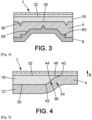
Fig. 3 ] est une section d'une partie du composant de garniture illustré sur lafigure 1 ; - [
Fig. 4 ] est une partie agrandie de lafigure 2 ; et - [
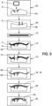
Fig. 5 ] est un diagramme des étapes du procédé de fabrication d'un composant de garniture selon l'invention. - Dans la description qui va suivre, les termes « haut », « bas », « inférieur » et « supérieur » sont définis lorsque le composant de garniture selon l'invention est disposé comme illustré sur la
figure 1 , et ne sont nullement limitatifs. - En référence à la
figure 1 , le composant de garniture 2 de véhicule selon l'invention comporte un panneau de support 4, une pièce de guidage 6 de coussin gonflable, un revêtement décoratif 7 fixé sur le panneau de support et sur une partie de la pièce de guidage 6 et un cadre de renfort 8 fixé sous le panneau de support. - Le composant de garniture 2 est par exemple une planche de bord de véhicule ou une partie de planche de bord de véhicule. En variante, le composant de garniture 2 est une console centrale de véhicule ou un panneau de porte de véhicule.
- Le panneau de support 4 donne sa forme géométrique au composant de garniture 2. Le panneau de support 4 thermocompressé présente une épaisseur de 1, 4 millimètres à 2,5 millimètres.
- Le panneau de support 4, la pièce de guidage 6 et le cadre de renfort 8 sont fixés les uns aux autres par compression à chaud.
- Le panneau de support 4 est muni d'une ouverture traversante 10 et d'un bord périphérique 12 entourant l'ouverture.
- Le panneau de support 4 est réalisé par thermocompression. Par exemple, le panneau de support 4 est réalisé par compression à chaud. Le panneau de support 4 comprend des fibres. Le panneau de support 4 comprend par exemple des fibres naturelles et un matériau thermoplastique. Les fibres naturelles sont par exemple des fibres de chanvre, de bois, de lin, de kénaf et/ou de sisal, de préférence des fibres de bois. Le matériau thermoplastique est par exemple du polypropylène (PP) et/ou du polyéthylène téréphtalate (PET), de préférence du polypropylène (PP). Le panneau de support 4 se présente, avant l'étape de thermocompression, sous la forme d'un tapis non-tissé comprenant des fibres entremêlées. Dans un exemple particulier, le tapis non-tissé comprend des fibres naturelles et des fibres thermoplastiques entremêlées. Le tapis non tissé est par exemple formé par aiguilletage des fibres. Le tapis non tissé présente une épaisseur de 8 millimètres à 14 millimètres avant l'étape de thermocompression.
- La pièce de guidage 6 de coussin gonflable comporte un canal 14, un volet 16 refermant au moins en partie une première extrémité 14A du canal 14 et une collerette 18 disposée autour du canal dans le prolongement du volet 16. La deuxième extrémité du canal, opposée à la première extrémité 14A, est référencée 14B.
- Selon un mode de réalisation particulier, la pièce de guidage 6 comprend plusieurs volets 16 refermant au moins en partie la première extrémité du canal 14, par exemple deux volets 16, comme représenté sur la
figure 1 . - La pièce de guidage 6 est de préférence réalisée d'une seule pièce par moulage, par exemple par moulage par injection, d'une matière plastique.
- Le canal 14 est agencé dans l'ouverture 10 du panneau de support 4. Il est généralement appelé canal de tir. Le canal 14 délimite un passage interne pour le déploiement du coussin gonflable de sécurité dans l'habitacle du véhicule. Le passage interne du canal 14 est opposé à un contour externe du canal 14.
- Le canal 14 est apte à guider un coussin gonflable de sécurité, lorsque celui-ci se déploie. Le canal 14 présente une forme tubulaire.
- Le canal 14 présente par exemple une section transversale de forme rectangulaire. Le canal 14 comprend par exemple quatre parois opposées deux à deux. La canal 14 s'étend autour d'un axe A-A. Le canal 14 s'étend depuis la première extrémité 14A du canal 14 à la deuxième extrémité 14B du canal 14. Le canal comporte au voisinage de la deuxième extrémité 14B du canal 14, autrement dit dans sa partie inférieure, des lumières 20 dans lesquelles un carter 22 est crocheté. Le carter 22 est également fixé au canal 14 par des moyens de fixation non représentés. Le carter 22 contient un générateur et un coussin gonflable de sécurité. Le générateur est apte à générer le déploiement du coussin gonflable de sécurité. Le coussin gonflable de sécurité est apte à se déployer dans l'habitacle du véhicule en passant par le canal 14, lorsque le véhicule est soumis à un choc.
- Le pourtour du canal 14 comporte dans sa partie médiane, s'étendant entre la première extrémité et la deuxième extrémité du canal 14, des éléments de verrouillage 24 et/ou des nervures 26 représentés schématiquement sur les figures. Par « pourtour du canal 14 », on entend le contour externe du canal 14, plus particulièrement la face externe des parois du canal 14. Ces nervures 26 s'étendent au niveau du cadre de renfort 8. Le cadre de renfort 8 étant, au moins en partie, en appui contre les nervures 26.
- Le canal 14 peut par exemple comporter entre quatre et seize éléments de verrouillage 24 et entre quatre et seize nervures 26, disposés chacun et chacune sur une paroi du canal.
- Les éléments de verrouillage 24 sont propres à bloquer le cadre de renfort 8 en butée contre le bord périphérique 12 du panneau de support 4. Les éléments de verrouillage 24 comprennent chacun une patte de fixation à emboitage élastique. De préférence, les pattes de fixation à emboitage élastique sont réversibles. Les pattes de fixation à emboitage élastique se déforment lors de l'assemblage et de la fixation de la pièce de guidage 6 au panneau de support 4. Puis, elles reprennent leur forme initiale, comme explicité dans le procédé de fabrication décrit ci-après. Avantageusement, les éléments de verrouillage 24 sécurisent la fixation de la pièce de guidage 6 au panneau de support 4.
- Les nervures 26 sont par exemple agencées entre les éléments de verrouillage 24 et la collerette 18. Avantageusement, les nervures permettent un positionnement précis du cadre de renfort 8 par rapport à la pièce de guidage 6.
- Le volet 16 referme au moins une partie de la première extrémité du canal 14, autrement dit l'extrémité supérieure du canal 14. Le volet 16 est relié au canal 14 par une charnière 27 autour de laquelle le volet 16 est mobile en rotation lors du déploiement du coussin gonflable de sécurité entre une position fermée dans laquelle le volet 16 referme au moins une partie de la première extrémité du canal 14 et une position ouverte dans laquelle le volet 16 libère l'au moins une partie de la première extrémité du canal 14. Dans le mode de réalisation dans lequel la pièce de guidage 6 comprend plusieurs volets 16, chaque volet 16 est relié au canal 14 par une charnière 27 et une ligne d'affaiblissement 28 est arrangée à la jonction entre les volets 16. Par exemple, lorsque la pièce de guidage 6 comprend deux volets 16, une ligne d'affaiblissement 28 est arrangée à la jonction entre les deux volets 16, comme illustré à la
figure 1 . La ligne d'affaiblissement 28 est par exemple formée par une restriction d'épaisseur du volet 16. La ligne d'affaiblissement 28 est propre à se déchirer, avantageusement sans projeter des particules du volet 16 dans l'habitacle, lors du déploiement du coussin gonflable de sécurité. - La collerette 18 est agencée autour de la première extrémité 14A du canal 14, autrement dit l'extrémité supérieure du canal 14, dans le prolongement du volet 16. Par « agencée autour de la première extrémité du canal 14 », on entend que la collerette 18 s'étend à partir de la première extrémité 14A du canal 14 vers l'extérieur du canal 14.
- Selon un mode de réalisation particulier, la collerette 18 est agencée autour de la totalité de la première extrémité du canal 14.
- La collerette 18 forme avec le volet 16 une surface sensiblement plane sur laquelle le revêtement décoratif 7 est fixé. La collerette 18 présente une face d'appui 30, une face opposée 32 à la face d'appui 30 et une tranche 34 reliant la face d'appui 30 à la face opposée 32.
- Le revêtement décoratif 7 est fixé sur la face opposée 32.
- La face d'appui 30 est fixée par compression à chaud au bord périphérique 12 du panneau de support 4. La face d'appui 30 est fixée à une face supérieure du bord périphérique 12. De préférence, la face d'appui 30 est munie d'un ou plusieurs relief(s) 36 pour augmenter l'adhésion de la collerette 18 au panneau de support 4, comme représenté sur la
figure 3 . Ces reliefs 36 sont, par exemple, constitués par des picots, des nervures, des bosses etc. Ces reliefs 36 augmentent la surface d'adhésion. Ces reliefs présentent par exemple une hauteur comprise entre 0,5 millimètre et 2,5 millimètres. La densité de ces reliefs est comprise entre 5 et 15 par centimètre carré. - En référence à la
figure 4 , la tranche 34 de la collerette 18 présente, selon une direction B partant de la face d'appui 30 et allant vers la face opposée 32, un profil en S 38 et un chanfrein 40 permettant d'améliorer la fixation du panneau de support à la pièce de guidage et d'assurer la planéité de l'interface entre la pièce de guidage et le panneau de support. - En particulier, le profil en S 38 comporte, selon la direction B, une première surface arrondie 42 ayant un centre de courbure situé à l'intérieur de la collerette 18 suivie d'une surface 44 sensiblement plane et inclinée par rapport à un plan vertical, continué par une deuxième surface arrondie 46 ayant un centre de courbure à l'extérieur de la collerette 18.
- De préférence, la surface 44 présente un angle d'inclinaison α compris entre 0° et 30° par rapport à un plan vertical.
- Le chanfrein 40 délimite une portion d'épaisseur réduite située au niveau de la tranche 34, formant une marche à l'extrémité de la collerette 18. Il permet d'éviter un défaut tel que par exemple une bavure, lors de l'injection de la collerette 18 de la pièce de guidage 6. L'épaisseur de la collerette 18 au début du chanfrein est sensiblement égale à 0,5 millimètre.
- De préférence, le chanfrein 40 présente un angle d'inclinaison β compris entre 0° et 60° par rapport à un plan vertical.
- Le revêtement décoratif 7 est fixé sur le panneau de support 4, sur la collerette 18 et sur le volet 16. Il est propre à se déchirer lorsque le volet 16 s'ouvre et que le coussin gonflable se déploie.
- Dans le mode de réalisation représenté sur la
figure 1 , le revêtement décoratif 7 comprend une couche de mousse et un revêtement externe. Le revêtement décoratif 7 présente une épaisseur comprise entre 0,8 millimètre et 3,5 millimètres. La couche de mousse s'étend entre le revêtement externe et la surface formée par le panneau de support 4, la collerette 18 et le volet 16. Le revêtement externe peut être réalisé dans tout type de peau tel que par exemple, un revêtement en polypropylène, un textile ou un cuir. - Le cadre de renfort 8 est une pièce rapportée agencée autour du canal 14. Le cadre de renfort 8 est fixée au bord périphérique 12 du panneau de support 4 par compression à chaud. Le cadre de renfort 8 est fixé à une face inférieure du bord périphérique 12, opposée à la face supérieure du bord périphérique 12. Le cadre de renfort 8 est adapté pour fixer la position de la pièce de guidage 6 par rapport au panneau de support 4. En particulier, il permet de plaquer et de fixer le bord périphérique 12 du panneau de support 4 contre la collerette 18 pendant l'opération de compression à chaud. Ainsi, le bord périphérique 12 du panneau de support 4 est maintenu entre le cadre de renfort 8 et la collerette 18.
- Le cadre de renfort 8 présente une forme complémentaire de la forme du canal 14. Ainsi, le cadre de renfort 8 présente par exemple une forme sensiblement rectangulaire comprenant quatre branches, comme illustrée sur la
figure 5 . Le cadre de renfort 8 est de préférence réalisé d'une seule pièce par moulage, par exemple par moulage par injection, d'une matière plastique, comprenant par exemple du polypropylène. - Le cadre de renfort 8 comprend un anneau 48 s'étendant dans un plan sensiblement perpendiculaire à la direction axiale A-A, et une jupe 50 s'étendant sensiblement perpendiculairement à l'anneau 48. Chaque branche du cadre de renfort 8 présente une section en forme de L.
- En référence à la
figure 2 , l'anneau 48 comporte un bord extérieur libre 52 et une ouverture centrale 54 délimitant un bord intérieur 56. La jupe 50 s'étend à partir du bord intérieur 56 de l'anneau 48 vers un côté inférieur de l'anneau 48. La jupe 50 s'étend entre une extrémité liée à l'anneau 48 et une extrémité libre, opposée à l'extrémité liée à l'anneau 48. De préférence, la dimension D de l'anneau 48 définie entre le bord intérieur 56 et le bord extérieur 52 est comprise entre 5 millimètres et 50 millimètres et est, de préférence comprise entre 10 millimètres et 30 millimètres. - Cette dimension entre les bords intérieur 56 et extérieur 52 permet également de palier à un défaut de positionnement de la découpe du panneau de support.
- Le bord intérieur 56 de l'anneau 48 est au contact des nervures 26 du canal 14 pour assurer un positionnement précis du cadre de renfort 8 par rapport à la pièce de guidage 6.
- L'anneau 48 comporte une face 58 fixée par compression à chaud au bord périphérique 12 du panneau de support. De préférence, cette face 58 est munie d'un relief ou de plusieurs reliefs 60 pour augmenter l'adhésion de l'anneau au panneau de support. Ces reliefs 60 sont constitués par des picots, des nervures ou des bosses, comme visible sur la
figure 3 . Ces reliefs 60 présentent par exemple une hauteur comprise entre 0,5 millimètre et 2,5 millimètres. La densité de ces reliefs est comprise entre 5 et 15 par centimètre carré. - La jupe 50 présente une forme complémentaire au canal 14. Elle est emboitée autour du canal.
- Avantageusement, la jupe 50 renforce la stabilité et le bon positionnement du cadre de renfort 8 par rapport à la pièce de guidage 6.
- Les éléments de verrouillage 24 de la pièce de guidage 6 sont en appui contre l'extrémité libre de la jupe 50.
- En variante, le canal 14 comporte un unique élément de verrouillage 24.
- En variante, les pattes de fixation à emboitage élastique ne sont pas réversibles. Dans ce cas, leur position déformée après assemblage leur permet de bloquer le cadre de renfort 8 en butée contre le bord périphérique 12 du panneau de support. Selon un mode de réalisation, l'anneau 48 comporte une face 58 fixée au bord périphérique 12 du panneau de support, et dans lequel ladite face 58 de l'anneau est munie d'au moins un relief 60 pour augmenter l'adhésion de l'anneau 48 au panneau de support 4.
- Selon un mode de réalisation, la collerette 18 comporte une face d'appui 30 fixée au bord périphérique 12 du panneau de support 4, ladite face d'appui 30 étant munie d'au moins un relief 36 pour augmenter l'adhésion de la collerette 18 au panneau de support 4.
- Selon un mode de réalisation, la collerette 18 comporte une face d'appui 30 fixée au bord périphérique 12 du panneau de support 4, une face opposée 32 à la face d'appui et une tranche 34 reliant la face d'appui 30 à la face opposée 32, la tranche 34 comportant, selon une direction partant de la face d'appui 30 et allant vers la face opposée 32, un profil en forme S 38 et un chanfrein 40.
- Selon un mode de réalisation, l'anneau 48 comporte une face 58 fixée au bord périphérique 12 du panneau de support, et ladite face 58 de l'anneau est munie d'au moins un relief 60 pour augmenter l'adhésion de l'anneau 48 au panneau de support 4.
- Selon un mode de réalisation, la collerette 18 comporte une face d'appui 30 fixée au bord périphérique 12 du panneau de support 4, ladite face d'appui 30 étant munie d'au moins un relief 36 pour augmenter l'adhésion de la collerette 18 au panneau de support 4.
- Selon un mode de réalisation, la collerette 18 comporte une face d'appui 30 fixée au bord périphérique 12 du panneau de support 4, une face opposée 32 à la face d'appui et une tranche 34 reliant la face d'appui 30 à la face opposée 32 la tranche 34 comportant, selon une direction partant de la face d'appui 30 et allant vers la face opposée 32, un profil en forme S 38 et un chanfrein 40.
- Selon un mode de réalisation, le cadre de renfort 8 est réalisé en matière plastique. En référence à la
figure 5 , le procédé fabrication du composant de garniture selon l'invention débute par une étape 62 au cours de laquelle le cadre de renfort 8 est disposé à l'intérieur d'une cavité de moulage d'une première partie de moule 64. - Au cours d'une étape 66, la pièce de guidage 6 de coussin gonflable est agencée dans une cavité de moulage d'une deuxième partie de moule 68.
- Au cours d'une étape 70, le panneau de support 4 est chauffé à une température comprise entre 160°C et 220°C, de préférence entre 200°C et 220°C, en particulier entre 205°C et 210 °C.
- Au cours d'une étape 72, le panneau de support 4 chauffé est posé sur la cavité de moulage de la première partie de moule 64 et sur le cadre de renfort 8, notamment sur l'anneau 48 du cadre de renfort. Le panneau de support commence à se déformer, notamment par gravité et/ou par une action du moule, pour épouser la forme de la cavié de moulage de la première partie de moule 64 et du cadre de renfort 8.
- Au cours d'une étape 74, une ouverture 10 est découpée dans le panneau de support par des éléments de découpe 75. Les éléments de découpe 75 prennent appui sur le cadre de renfort 8 pour découper l'ouverture 10.
- Au cours d'une étape 76, la première partie de moule 64 et la deuxième partie de moule 68 sont assemblées en insérant le canal 14 de la pièce de guidage 6 dans l'ouverture10 du panneau de support 4 et dans le cadre de renfort 8. Lors de l'insertion du canal 14 dans le cadre de renfort 8, les pattes de fixation à déformation élastique des éléments de verrouillage 24 se déforment. Puis, elles reprennent leur position initiale. Dans cette position initiale, les pattes de fixation sont disposées contre l'extrémité libre de la jupe 50 du cadre de renfort 8. Elles forment une butée de sécurité en cas où la fixation par compression à chaud se désolidarise.
- Au cours d'une étape 78, la première partie de moule 64 et la deuxième partie de moule 68 sont comprimées l'un contre l'autre. Au cours de cette compression, le bord périphérique 12 du panneau de support 4 est fixé contre la collerette18 de la pièce de guidage 6 et contre le cadre de renfort 8, en particulier contre l'anneau 48 du cadre de renfort 8. L'étape de compression 78 doit être effectuée au maximum 20 secondes après chauffage du panneau de support.
- Au cours d'une étape 80, le revêtement décoratif 7 est fixé sur la face supérieure du panneau de support 4 et sur la face supérieure du volet 16 et de la collerette 18.
- Au cours d'une étape optionnelle 82, des ouvertures 84 sont pratiquées au travers du revêtement décoratif 7 et du panneau de support 4. Ces ouvertures sont destinées aux passages d'équipements tel qu'un autoradio ou un aérateur. Les étapes du procédé ont lieu de l'étape 62 à l'étape 82, comme illustré sur la
figure 5 .
Claims (10)
- Composant de garniture (2) de véhicule, le composant de garniture comprenant :- un panneau de support (4) thermocompressé muni d'une ouverture (10) et d'un bord périphérique (12) entourant l'ouverture,- une pièce de guidage (6) de coussin gonflable comportant un canal (14) agencé dans l'ouverture (10) du panneau de support (4), un volet (16) refermant au moins en partie une première extrémité (14A) du canal (14) et une collerette (18) agencée autour du canal dans le prolongement du volet, le bord périphérique (12) du panneau de support étant fixé contre la collerette (18),caractérisé en ce qu'il comporte en outre un cadre de renfort (8) propre à fixer la position de la pièce de guidage (6) par rapport au panneau de support (4), le cadre de renfort (8) étant une pièce rapportée emmanchée autour du canal (14) et fixée au bord périphérique (12) du panneau de support (4).
- Composant de garniture (2) de véhicule selon la revendication 1, dans lequel le canal (14) est pourvu d'au moins un élément de verrouillage (24) propre à bloquer le cadre de renfort (8) en butée contre le bord périphérique (12) du panneau de support.
- Composant de garniture (2) de véhicule selon la revendication 2, dans lequel le au moins un élément de verrouillage (24) comprend une patte de fixation à emboitage élastique.
- Composant de garniture (2) de véhicule selon l'une quelconque des revendications 1 à 3, dans lequel le cadre de renfort (8) comprend un anneau (48) s'étendant dans un plan parallèle à la collerette (18), et une jupe (50) s'étendant perpendiculairement à l'anneau (48) et enserrant le canal (14).
- Composant de garniture (2) de véhicule selon la combinaison des revendications 2 et 4, dans lequel ledit au moins un élément de verrouillage (24) est en appui contre une extrémité libre de la jupe (50).
- Composant de garniture (2) de véhicule selon l'une quelconque des revendications 4 et 5, dans lequel l'anneau (48) est adapté pour plaquer le bord périphérique (12) du panneau de support (4) contre la collerette (18), l'anneau (48) comportant un bord extérieur (52) et une ouverture centrale (54) délimitant un bord intérieur (56), et dans lequel la dimension (D) de l'anneau définie entre le bord intérieur (56) et le bord extérieur (52) est comprise entre 5 millimètres et 50 millimètres et est, de préférence, comprise entre 10 millimètres et 30 millimètres.
- Composant de garniture (2) de véhicule selon l'une quelconque des revendications 1 à 6, dans lequel le pourtour du canal (14) comporte des nervures (26) s'étendant selon une direction axiale (A-A) ; le cadre de renfort (8) s'étendant au moins en partie contre les nervures (26).
- Composant de garniture (2) de véhicule selon l'une quelconque des revendications 1 à 7, dans lequel le cadre de renfort (8) maintient le bord périphérique (12) du panneau de support contre la collerette (18).
- Procédé de fabrication d'un composant de garniture (2) pour véhicule, en particulier pour véhicule automobile, le composant de garniture (2) comprenant un panneau de support (4) thermocompressé, un cadre de renfort (8) et une pièce de guidage (6) de coussin gonflable comportant un canal (14), un volet (16) refermant au moins en partie une première extrémité du canal et une collerette (18) disposée autour du canal (14) dans le prolongement du volet (16), le procédé comportant les étapes suivantes :- disposer (62) le cadre de renfort (8) à l'intérieur d'une cavité de moulage d'une première partie de moule (64),- chauffer (70) un panneau de support (4);- disposer (72) le panneau de support (4) chauffé sur la cavité de moulage du premier moule et sur une partie du cadre de renfort (8);- découper (74) une ouverture (10) dans le panneau de support (4) en regard du cadre de renfort (4);- disposer (66) la pièce de guidage (6) de coussin gonflable dans une cavité de moulage d'une deuxième partie de moule (68) ;- assembler (76) la première partie de moule (64) et la deuxième partie de moule (68) en insérant le canal (14) de la pièce de guidage (6) dans l'ouverture (10) du panneau de support (4) et dans le cadre de renfort (8);- fixer (78) le panneau de support (4) à la collerette (18) et à une partie du cadre de renfort (8) en comprimant la deuxième partie de moule (68) contre la première partie de moule (64).
- Procédé de fabrication selon la revendication 9 dans lequel le canal (14) de la pièce de guidage (6) est pourvu d'au moins un élément de verrouillage (24), et dans lequel ledit au moins un élément de verrouillage (24) se déforme de façon réversible lors de l'insertion du canal (14) de la pièce de guidage (6) dans l'ouverture (10) du panneau de support (4) et dans le cadre de renfort (8) puis reprend sa forme initiale pour bloquer le cadre de renfort (8) en butée contre un bord périphérique (12) du panneau de support (4).
Applications Claiming Priority (1)
| Application Number | Priority Date | Filing Date | Title |
|---|---|---|---|
| FR2111397A FR3128427B1 (fr) | 2021-10-27 | 2021-10-27 | Composant de garniture de véhicule et un procédé de fabrication d’un tel composant de garniture |
Publications (2)
| Publication Number | Publication Date |
|---|---|
| EP4173899A1 true EP4173899A1 (fr) | 2023-05-03 |
| EP4173899B1 EP4173899B1 (fr) | 2024-06-12 |
Family
ID=79170999
Family Applications (1)
| Application Number | Title | Priority Date | Filing Date |
|---|---|---|---|
| EP22203742.6A Active EP4173899B1 (fr) | 2021-10-27 | 2022-10-26 | Composant de garniture de véhicule et un procédé de fabrication d'un tel composant de garniture |
Country Status (5)
| Country | Link |
|---|---|
| US (1) | US12434654B2 (fr) |
| EP (1) | EP4173899B1 (fr) |
| CN (1) | CN116022087A (fr) |
| ES (1) | ES2984166T3 (fr) |
| FR (1) | FR3128427B1 (fr) |
Families Citing this family (1)
| Publication number | Priority date | Publication date | Assignee | Title |
|---|---|---|---|---|
| DE102022101281A1 (de) * | 2022-01-20 | 2023-07-20 | Lisa Dräxlmaier GmbH | Interieurbauteil für fahrzeuge |
Citations (2)
| Publication number | Priority date | Publication date | Assignee | Title |
|---|---|---|---|---|
| JP2010069854A (ja) * | 2008-09-22 | 2010-04-02 | Inoac Corp | 発泡体付き成形部材 |
| US20150217712A1 (en) * | 2012-08-27 | 2015-08-06 | Johnson Controls Technology Company | System and method for mounting an airbag chute assembly within a vehicle trim component |
Family Cites Families (20)
| Publication number | Priority date | Publication date | Assignee | Title |
|---|---|---|---|---|
| JP3321560B2 (ja) * | 1998-11-16 | 2002-09-03 | 株式会社イノアックコーポレーション | エアバッグドア部の構造 |
| JP3497763B2 (ja) * | 1999-03-24 | 2004-02-16 | 日本プラスト株式会社 | 自動車のエアバッグ装置 |
| JP2001088646A (ja) * | 1999-09-22 | 2001-04-03 | Mitsuboshi Belting Ltd | エアバッグドア構造 |
| JP2001253311A (ja) * | 2000-03-09 | 2001-09-18 | Takata Corp | 助手席用エアバッグ装置 |
| JP3807216B2 (ja) * | 2000-09-29 | 2006-08-09 | 豊田合成株式会社 | エアバッグカバー |
| US7121577B2 (en) * | 2002-06-24 | 2006-10-17 | Delphi Technologies, Inc. | Cover for airbag module and method of making |
| FR2842472B1 (fr) | 2002-07-17 | 2005-02-18 | Faurecia Interieur Ind | Ensemble de masquage d'un coussin gonflable de securite a organes de renfort et procede de realisation correspondants |
| JP4426878B2 (ja) | 2004-03-10 | 2010-03-03 | 三光合成株式会社 | 自動車用エアーバッグ装置 |
| JP4569272B2 (ja) | 2004-11-12 | 2010-10-27 | タカタ株式会社 | エアバッグ装置 |
| US7434828B2 (en) | 2005-03-22 | 2008-10-14 | Inoac Corporation | Molded member with foamed body |
| JP4832052B2 (ja) * | 2005-10-31 | 2011-12-07 | ダイキョーニシカワ株式会社 | エアバッグドア部付き車両用内装品 |
| US7914039B2 (en) * | 2009-03-16 | 2011-03-29 | Automotive Components Holdings, Llc | Interlocking one piece molded passenger air bag chute |
| US10464280B2 (en) | 2011-08-30 | 2019-11-05 | Shanghai Yanfeng Jinqiao Automotive Trim Systems Co. Ltd. | Trim component for vehicle interior |
| FR2987585B1 (fr) * | 2012-03-02 | 2015-01-30 | Faurecia Interieur Ind | Dispositif de securite pour vehicule |
| US8783711B2 (en) * | 2012-12-17 | 2014-07-22 | Chrysler Group Llc | Low mass passenger airbag design |
| FR3034384B1 (fr) * | 2015-03-31 | 2017-04-14 | Faurecia Interieur Ind | Procede de fabrication d'un element d'habillage interieur de vehicule adapte pour recouvrir un sac gonflable de securite. |
| CN206426987U (zh) * | 2017-01-22 | 2017-08-22 | 上海延锋金桥汽车饰件系统有限公司 | 一种气囊框组件 |
| JP6753380B2 (ja) * | 2017-09-28 | 2020-09-09 | 豊田合成株式会社 | エアバッグ装置 |
| HUE056064T2 (hu) | 2018-01-22 | 2022-01-28 | Motherson Innovations Co Ltd | Légzsákvezetõ berendezés egy gépjármû egy légzsákjának vezetésére, légzsák egység, ami tartalmaz egy ilyen légzsákvezetõ berendezést, valamint belsõ burkoló elem és eljárás egy ilyen belsõ burkoló elem elõállítására, ami tartalmaz egy ilyen légzsákvezet.. |
| FR3106329B1 (fr) * | 2020-01-20 | 2023-07-14 | Smrc Automotive Holdings Netherlands Bv | Système d’assemblage d’un canal d’airbag au travers un panneau support |
-
2021
- 2021-10-27 FR FR2111397A patent/FR3128427B1/fr active Active
-
2022
- 2022-10-24 CN CN202211299657.3A patent/CN116022087A/zh active Pending
- 2022-10-26 ES ES22203742T patent/ES2984166T3/es active Active
- 2022-10-26 EP EP22203742.6A patent/EP4173899B1/fr active Active
- 2022-10-27 US US17/975,109 patent/US12434654B2/en active Active
Patent Citations (2)
| Publication number | Priority date | Publication date | Assignee | Title |
|---|---|---|---|---|
| JP2010069854A (ja) * | 2008-09-22 | 2010-04-02 | Inoac Corp | 発泡体付き成形部材 |
| US20150217712A1 (en) * | 2012-08-27 | 2015-08-06 | Johnson Controls Technology Company | System and method for mounting an airbag chute assembly within a vehicle trim component |
Also Published As
| Publication number | Publication date |
|---|---|
| FR3128427A1 (fr) | 2023-04-28 |
| US12434654B2 (en) | 2025-10-07 |
| FR3128427B1 (fr) | 2025-03-21 |
| CN116022087A (zh) | 2023-04-28 |
| EP4173899B1 (fr) | 2024-06-12 |
| ES2984166T3 (es) | 2024-10-29 |
| US20230131895A1 (en) | 2023-04-27 |
Similar Documents
| Publication | Publication Date | Title |
|---|---|---|
| EP2674274B1 (fr) | Elément de garnissage et procédé de fabrication associé | |
| EP0649736A1 (fr) | Tablette arrière de véhicule automobile et procédé de fabrication | |
| FR3007348A1 (fr) | Dispositif de securite pour vehicule | |
| KR101776465B1 (ko) | 일체형 크래쉬패드 및 그 제조방법 | |
| FR3007349A1 (fr) | Dispositif de securite pour vehicule | |
| FR3007347A1 (fr) | Procede pour mouler par injection un boitier de coussin de securite gonflable. | |
| EP4173899B1 (fr) | Composant de garniture de véhicule et un procédé de fabrication d'un tel composant de garniture | |
| FR2856351A1 (fr) | Armature de dossier de siege de vehicule automobile, et procede de realisation d'une telle armature | |
| WO2016020505A1 (fr) | Procédé de fabrication d'une pièce d'équipement automobile et pièce associée | |
| FR3028817A1 (fr) | Piece automobile d'ecrantage acoustique et son procede de fabrication | |
| EP3838543B1 (fr) | Procédé de réalisation d'un coussin pour élément de siège de véhicule automobile | |
| FR2955812A1 (fr) | Tablette autoportante de recouvrement d'un compartiment a bagages de vehicule automobile | |
| EP1386711B1 (fr) | Procédé pour réaliser une pièce revêtue d'un médaillon souple | |
| WO2001098051A1 (fr) | Procede de revetement et piece correspondante | |
| FR2969973A1 (fr) | Composant pour un vehicule automobile, procede de fabrication du composant et moule de fabrication | |
| EP1798112B1 (fr) | Procédé de moulage par injection plastique d'une pièce de garnissage, et pièce de garnissage issue de ce procédé | |
| EP2127943B1 (fr) | Corps de dossier de siège rabattable pour véhicule | |
| FR3072341A1 (fr) | Piece d'equipement interieur d'un vehicule et procede de fabrication associe | |
| EP3753788B1 (fr) | Coque interne d'une console centrale de véhicule automobile | |
| FR3117060A1 (fr) | Pièce d’équipement de véhicule automobile et procédé de fabrication associé | |
| FR2979871A1 (fr) | Piece d'habillage interieur et procede pour sa fabrication | |
| FR2869005A1 (fr) | Piece d'equipement pour vehicule automobile, procede de realisation et vehicule automobile associes. | |
| FR2792869A1 (fr) | Procede de fabrication d'une piece thermoplastique bi-matiere et extracteur obtenu selon ce procede | |
| FR3069822B1 (fr) | Procede de surmoulage d’un panneau de garniture avec une couche de protection pour textile fragile | |
| FR3164410A1 (fr) | Procédé de fabrication d’un panneau de garnissage de véhicule et panneau de garnissage ainsi obtenu |
Legal Events
| Date | Code | Title | Description |
|---|---|---|---|
| PUAI | Public reference made under article 153(3) epc to a published international application that has entered the european phase |
Free format text: ORIGINAL CODE: 0009012 |
|
| STAA | Information on the status of an ep patent application or granted ep patent |
Free format text: STATUS: THE APPLICATION HAS BEEN PUBLISHED |
|
| AK | Designated contracting states |
Kind code of ref document: A1 Designated state(s): AL AT BE BG CH CY CZ DE DK EE ES FI FR GB GR HR HU IE IS IT LI LT LU LV MC ME MK MT NL NO PL PT RO RS SE SI SK SM TR |
|
| STAA | Information on the status of an ep patent application or granted ep patent |
Free format text: STATUS: REQUEST FOR EXAMINATION WAS MADE |
|
| 17P | Request for examination filed |
Effective date: 20231017 |
|
| RBV | Designated contracting states (corrected) |
Designated state(s): AL AT BE BG CH CY CZ DE DK EE ES FI FR GB GR HR HU IE IS IT LI LT LU LV MC ME MK MT NL NO PL PT RO RS SE SI SK SM TR |
|
| GRAP | Despatch of communication of intention to grant a patent |
Free format text: ORIGINAL CODE: EPIDOSNIGR1 |
|
| STAA | Information on the status of an ep patent application or granted ep patent |
Free format text: STATUS: GRANT OF PATENT IS INTENDED |
|
| RIC1 | Information provided on ipc code assigned before grant |
Ipc: B60R 21/217 20110101ALN20240102BHEP Ipc: B29C 43/18 20060101ALI20240102BHEP Ipc: B60R 21/215 20110101AFI20240102BHEP |
|
| RIC1 | Information provided on ipc code assigned before grant |
Ipc: B60R 21/217 20110101ALN20240109BHEP Ipc: B29C 43/18 20060101ALI20240109BHEP Ipc: B60R 21/215 20110101AFI20240109BHEP |
|
| INTG | Intention to grant announced |
Effective date: 20240124 |
|
| GRAS | Grant fee paid |
Free format text: ORIGINAL CODE: EPIDOSNIGR3 |
|
| GRAA | (expected) grant |
Free format text: ORIGINAL CODE: 0009210 |
|
| STAA | Information on the status of an ep patent application or granted ep patent |
Free format text: STATUS: THE PATENT HAS BEEN GRANTED |
|
| AK | Designated contracting states |
Kind code of ref document: B1 Designated state(s): AL AT BE BG CH CY CZ DE DK EE ES FI FR GB GR HR HU IE IS IT LI LT LU LV MC ME MK MT NL NO PL PT RO RS SE SI SK SM TR |
|
| REG | Reference to a national code |
Ref country code: GB Ref legal event code: FG4D Free format text: NOT ENGLISH |
|
| REG | Reference to a national code |
Ref country code: CH Ref legal event code: EP |
|
| REG | Reference to a national code |
Ref country code: IE Ref legal event code: FG4D Free format text: LANGUAGE OF EP DOCUMENT: FRENCH |
|
| REG | Reference to a national code |
Ref country code: DE Ref legal event code: R096 Ref document number: 602022003931 Country of ref document: DE |
|
| REG | Reference to a national code |
Ref country code: SE Ref legal event code: TRGR |
|
| PG25 | Lapsed in a contracting state [announced via postgrant information from national office to epo] |
Ref country code: BG Free format text: LAPSE BECAUSE OF FAILURE TO SUBMIT A TRANSLATION OF THE DESCRIPTION OR TO PAY THE FEE WITHIN THE PRESCRIBED TIME-LIMIT Effective date: 20240612 |
|
| PG25 | Lapsed in a contracting state [announced via postgrant information from national office to epo] |
Ref country code: FI Free format text: LAPSE BECAUSE OF FAILURE TO SUBMIT A TRANSLATION OF THE DESCRIPTION OR TO PAY THE FEE WITHIN THE PRESCRIBED TIME-LIMIT Effective date: 20240612 Ref country code: HR Free format text: LAPSE BECAUSE OF FAILURE TO SUBMIT A TRANSLATION OF THE DESCRIPTION OR TO PAY THE FEE WITHIN THE PRESCRIBED TIME-LIMIT Effective date: 20240612 |
|
| REG | Reference to a national code |
Ref country code: LT Ref legal event code: MG9D |
|
| PG25 | Lapsed in a contracting state [announced via postgrant information from national office to epo] |
Ref country code: GR Free format text: LAPSE BECAUSE OF FAILURE TO SUBMIT A TRANSLATION OF THE DESCRIPTION OR TO PAY THE FEE WITHIN THE PRESCRIBED TIME-LIMIT Effective date: 20240913 |
|
| REG | Reference to a national code |
Ref country code: NL Ref legal event code: MP Effective date: 20240612 |
|
| REG | Reference to a national code |
Ref country code: ES Ref legal event code: FG2A Ref document number: 2984166 Country of ref document: ES Kind code of ref document: T3 Effective date: 20241029 |
|
| PG25 | Lapsed in a contracting state [announced via postgrant information from national office to epo] |
Ref country code: LV Free format text: LAPSE BECAUSE OF FAILURE TO SUBMIT A TRANSLATION OF THE DESCRIPTION OR TO PAY THE FEE WITHIN THE PRESCRIBED TIME-LIMIT Effective date: 20240612 |
|
| PG25 | Lapsed in a contracting state [announced via postgrant information from national office to epo] |
Ref country code: NO Free format text: LAPSE BECAUSE OF FAILURE TO SUBMIT A TRANSLATION OF THE DESCRIPTION OR TO PAY THE FEE WITHIN THE PRESCRIBED TIME-LIMIT Effective date: 20240912 Ref country code: LV Free format text: LAPSE BECAUSE OF FAILURE TO SUBMIT A TRANSLATION OF THE DESCRIPTION OR TO PAY THE FEE WITHIN THE PRESCRIBED TIME-LIMIT Effective date: 20240612 Ref country code: HR Free format text: LAPSE BECAUSE OF FAILURE TO SUBMIT A TRANSLATION OF THE DESCRIPTION OR TO PAY THE FEE WITHIN THE PRESCRIBED TIME-LIMIT Effective date: 20240612 Ref country code: GR Free format text: LAPSE BECAUSE OF FAILURE TO SUBMIT A TRANSLATION OF THE DESCRIPTION OR TO PAY THE FEE WITHIN THE PRESCRIBED TIME-LIMIT Effective date: 20240913 Ref country code: FI Free format text: LAPSE BECAUSE OF FAILURE TO SUBMIT A TRANSLATION OF THE DESCRIPTION OR TO PAY THE FEE WITHIN THE PRESCRIBED TIME-LIMIT Effective date: 20240612 Ref country code: BG Free format text: LAPSE BECAUSE OF FAILURE TO SUBMIT A TRANSLATION OF THE DESCRIPTION OR TO PAY THE FEE WITHIN THE PRESCRIBED TIME-LIMIT Effective date: 20240612 Ref country code: RS Free format text: LAPSE BECAUSE OF FAILURE TO SUBMIT A TRANSLATION OF THE DESCRIPTION OR TO PAY THE FEE WITHIN THE PRESCRIBED TIME-LIMIT Effective date: 20240912 |
|
| PG25 | Lapsed in a contracting state [announced via postgrant information from national office to epo] |
Ref country code: NL Free format text: LAPSE BECAUSE OF FAILURE TO SUBMIT A TRANSLATION OF THE DESCRIPTION OR TO PAY THE FEE WITHIN THE PRESCRIBED TIME-LIMIT Effective date: 20240612 |
|
| REG | Reference to a national code |
Ref country code: AT Ref legal event code: MK05 Ref document number: 1693975 Country of ref document: AT Kind code of ref document: T Effective date: 20240612 |
|
| PG25 | Lapsed in a contracting state [announced via postgrant information from national office to epo] |
Ref country code: NL Free format text: LAPSE BECAUSE OF FAILURE TO SUBMIT A TRANSLATION OF THE DESCRIPTION OR TO PAY THE FEE WITHIN THE PRESCRIBED TIME-LIMIT Effective date: 20240612 |
|
| PG25 | Lapsed in a contracting state [announced via postgrant information from national office to epo] |
Ref country code: PT Free format text: LAPSE BECAUSE OF FAILURE TO SUBMIT A TRANSLATION OF THE DESCRIPTION OR TO PAY THE FEE WITHIN THE PRESCRIBED TIME-LIMIT Effective date: 20241014 |
|
| PG25 | Lapsed in a contracting state [announced via postgrant information from national office to epo] |
Ref country code: PT Free format text: LAPSE BECAUSE OF FAILURE TO SUBMIT A TRANSLATION OF THE DESCRIPTION OR TO PAY THE FEE WITHIN THE PRESCRIBED TIME-LIMIT Effective date: 20241014 |
|
| PG25 | Lapsed in a contracting state [announced via postgrant information from national office to epo] |
Ref country code: PL Free format text: LAPSE BECAUSE OF FAILURE TO SUBMIT A TRANSLATION OF THE DESCRIPTION OR TO PAY THE FEE WITHIN THE PRESCRIBED TIME-LIMIT Effective date: 20240612 |
|
| PG25 | Lapsed in a contracting state [announced via postgrant information from national office to epo] |
Ref country code: EE Free format text: LAPSE BECAUSE OF FAILURE TO SUBMIT A TRANSLATION OF THE DESCRIPTION OR TO PAY THE FEE WITHIN THE PRESCRIBED TIME-LIMIT Effective date: 20240612 |
|
| PG25 | Lapsed in a contracting state [announced via postgrant information from national office to epo] |
Ref country code: IS Free format text: LAPSE BECAUSE OF FAILURE TO SUBMIT A TRANSLATION OF THE DESCRIPTION OR TO PAY THE FEE WITHIN THE PRESCRIBED TIME-LIMIT Effective date: 20241012 Ref country code: AT Free format text: LAPSE BECAUSE OF FAILURE TO SUBMIT A TRANSLATION OF THE DESCRIPTION OR TO PAY THE FEE WITHIN THE PRESCRIBED TIME-LIMIT Effective date: 20240612 |
|
| PG25 | Lapsed in a contracting state [announced via postgrant information from national office to epo] |
Ref country code: CZ Free format text: LAPSE BECAUSE OF FAILURE TO SUBMIT A TRANSLATION OF THE DESCRIPTION OR TO PAY THE FEE WITHIN THE PRESCRIBED TIME-LIMIT Effective date: 20240612 |
|
| PG25 | Lapsed in a contracting state [announced via postgrant information from national office to epo] |
Ref country code: RO Free format text: LAPSE BECAUSE OF FAILURE TO SUBMIT A TRANSLATION OF THE DESCRIPTION OR TO PAY THE FEE WITHIN THE PRESCRIBED TIME-LIMIT Effective date: 20240612 Ref country code: SK Free format text: LAPSE BECAUSE OF FAILURE TO SUBMIT A TRANSLATION OF THE DESCRIPTION OR TO PAY THE FEE WITHIN THE PRESCRIBED TIME-LIMIT Effective date: 20240612 |
|
| PG25 | Lapsed in a contracting state [announced via postgrant information from national office to epo] |
Ref country code: SM Free format text: LAPSE BECAUSE OF FAILURE TO SUBMIT A TRANSLATION OF THE DESCRIPTION OR TO PAY THE FEE WITHIN THE PRESCRIBED TIME-LIMIT Effective date: 20240612 |
|
| PG25 | Lapsed in a contracting state [announced via postgrant information from national office to epo] |
Ref country code: SM Free format text: LAPSE BECAUSE OF FAILURE TO SUBMIT A TRANSLATION OF THE DESCRIPTION OR TO PAY THE FEE WITHIN THE PRESCRIBED TIME-LIMIT Effective date: 20240612 Ref country code: SK Free format text: LAPSE BECAUSE OF FAILURE TO SUBMIT A TRANSLATION OF THE DESCRIPTION OR TO PAY THE FEE WITHIN THE PRESCRIBED TIME-LIMIT Effective date: 20240612 Ref country code: RO Free format text: LAPSE BECAUSE OF FAILURE TO SUBMIT A TRANSLATION OF THE DESCRIPTION OR TO PAY THE FEE WITHIN THE PRESCRIBED TIME-LIMIT Effective date: 20240612 Ref country code: PL Free format text: LAPSE BECAUSE OF FAILURE TO SUBMIT A TRANSLATION OF THE DESCRIPTION OR TO PAY THE FEE WITHIN THE PRESCRIBED TIME-LIMIT Effective date: 20240612 Ref country code: IS Free format text: LAPSE BECAUSE OF FAILURE TO SUBMIT A TRANSLATION OF THE DESCRIPTION OR TO PAY THE FEE WITHIN THE PRESCRIBED TIME-LIMIT Effective date: 20241012 Ref country code: EE Free format text: LAPSE BECAUSE OF FAILURE TO SUBMIT A TRANSLATION OF THE DESCRIPTION OR TO PAY THE FEE WITHIN THE PRESCRIBED TIME-LIMIT Effective date: 20240612 Ref country code: CZ Free format text: LAPSE BECAUSE OF FAILURE TO SUBMIT A TRANSLATION OF THE DESCRIPTION OR TO PAY THE FEE WITHIN THE PRESCRIBED TIME-LIMIT Effective date: 20240612 Ref country code: AT Free format text: LAPSE BECAUSE OF FAILURE TO SUBMIT A TRANSLATION OF THE DESCRIPTION OR TO PAY THE FEE WITHIN THE PRESCRIBED TIME-LIMIT Effective date: 20240612 |
|
| PG25 | Lapsed in a contracting state [announced via postgrant information from national office to epo] |
Ref country code: IT Free format text: LAPSE BECAUSE OF FAILURE TO SUBMIT A TRANSLATION OF THE DESCRIPTION OR TO PAY THE FEE WITHIN THE PRESCRIBED TIME-LIMIT Effective date: 20240612 |
|
| REG | Reference to a national code |
Ref country code: DE Ref legal event code: R082 Ref document number: 602022003931 Country of ref document: DE Representative=s name: PLASSERAUD IP GMBH, DE |
|
| REG | Reference to a national code |
Ref country code: DE Ref legal event code: R097 Ref document number: 602022003931 Country of ref document: DE |
|
| PG25 | Lapsed in a contracting state [announced via postgrant information from national office to epo] |
Ref country code: DK Free format text: LAPSE BECAUSE OF FAILURE TO SUBMIT A TRANSLATION OF THE DESCRIPTION OR TO PAY THE FEE WITHIN THE PRESCRIBED TIME-LIMIT Effective date: 20240612 |
|
| PLBE | No opposition filed within time limit |
Free format text: ORIGINAL CODE: 0009261 |
|
| STAA | Information on the status of an ep patent application or granted ep patent |
Free format text: STATUS: NO OPPOSITION FILED WITHIN TIME LIMIT |
|
| 26N | No opposition filed |
Effective date: 20250313 |
|
| PG25 | Lapsed in a contracting state [announced via postgrant information from national office to epo] |
Ref country code: MC Free format text: LAPSE BECAUSE OF FAILURE TO SUBMIT A TRANSLATION OF THE DESCRIPTION OR TO PAY THE FEE WITHIN THE PRESCRIBED TIME-LIMIT Effective date: 20240612 |
|
| PG25 | Lapsed in a contracting state [announced via postgrant information from national office to epo] |
Ref country code: LU Free format text: LAPSE BECAUSE OF NON-PAYMENT OF DUE FEES Effective date: 20241026 Ref country code: BE Free format text: LAPSE BECAUSE OF NON-PAYMENT OF DUE FEES Effective date: 20241031 |
|
| REG | Reference to a national code |
Ref country code: BE Ref legal event code: MM Effective date: 20241031 |
|
| PGFP | Annual fee paid to national office [announced via postgrant information from national office to epo] |
Ref country code: FR Payment date: 20250924 Year of fee payment: 4 |
|
| PGFP | Annual fee paid to national office [announced via postgrant information from national office to epo] |
Ref country code: SE Payment date: 20250923 Year of fee payment: 4 |
|
| PG25 | Lapsed in a contracting state [announced via postgrant information from national office to epo] |
Ref country code: IE Free format text: LAPSE BECAUSE OF NON-PAYMENT OF DUE FEES Effective date: 20241026 |
|
| PGFP | Annual fee paid to national office [announced via postgrant information from national office to epo] |
Ref country code: DE Payment date: 20250923 Year of fee payment: 4 |
|
| PG25 | Lapsed in a contracting state [announced via postgrant information from national office to epo] |
Ref country code: CY Free format text: LAPSE BECAUSE OF FAILURE TO SUBMIT A TRANSLATION OF THE DESCRIPTION OR TO PAY THE FEE WITHIN THE PRESCRIBED TIME-LIMIT; INVALID AB INITIO Effective date: 20221026 |
|
| PGFP | Annual fee paid to national office [announced via postgrant information from national office to epo] |
Ref country code: ES Payment date: 20251103 Year of fee payment: 4 |
|
| PG25 | Lapsed in a contracting state [announced via postgrant information from national office to epo] |
Ref country code: HU Free format text: LAPSE BECAUSE OF FAILURE TO SUBMIT A TRANSLATION OF THE DESCRIPTION OR TO PAY THE FEE WITHIN THE PRESCRIBED TIME-LIMIT; INVALID AB INITIO Effective date: 20221026 |