EP4168344B1 - Aufzugsanlage - Google Patents
Aufzugsanlage Download PDFInfo
- Publication number
- EP4168344B1 EP4168344B1 EP21734079.3A EP21734079A EP4168344B1 EP 4168344 B1 EP4168344 B1 EP 4168344B1 EP 21734079 A EP21734079 A EP 21734079A EP 4168344 B1 EP4168344 B1 EP 4168344B1
- Authority
- EP
- European Patent Office
- Prior art keywords
- rescue
- elevator system
- car
- safety brake
- actuator
- Prior art date
- Legal status (The legal status is an assumption and is not a legal conclusion. Google has not performed a legal analysis and makes no representation as to the accuracy of the status listed.)
- Active
Links
Images




Classifications
-
- B—PERFORMING OPERATIONS; TRANSPORTING
- B66—HOISTING; LIFTING; HAULING
- B66B—ELEVATORS; ESCALATORS OR MOVING WALKWAYS
- B66B5/00—Applications of checking, fault-correcting, or safety devices in elevators
- B66B5/02—Applications of checking, fault-correcting, or safety devices in elevators responsive to abnormal operating conditions
- B66B5/027—Applications of checking, fault-correcting, or safety devices in elevators responsive to abnormal operating conditions to permit passengers to leave an elevator car in case of failure, e.g. moving the car to a reference floor or unlocking the door
-
- B—PERFORMING OPERATIONS; TRANSPORTING
- B66—HOISTING; LIFTING; HAULING
- B66B—ELEVATORS; ESCALATORS OR MOVING WALKWAYS
- B66B7/00—Other common features of elevators
- B66B7/06—Arrangements of ropes or cables
- B66B7/08—Arrangements of ropes or cables for connection to the cars or cages, e.g. couplings
-
- B—PERFORMING OPERATIONS; TRANSPORTING
- B66—HOISTING; LIFTING; HAULING
- B66B—ELEVATORS; ESCALATORS OR MOVING WALKWAYS
- B66B9/00—Kinds or types of lifts in, or associated with, buildings or other structures
- B66B9/003—Kinds or types of lifts in, or associated with, buildings or other structures for lateral transfer of car or frame, e.g. between vertical hoistways or to/from a parking position
Definitions
- the EN 10 2014 220 966 A1 discloses an elevator system in which several cars are operated cyclically in a circular operation, similar to a paternoster. In contrast to the classic paternoster, each car is driven independently of the other cars and can therefore stop at any stop independently of the other cars. Transfer units are provided to transfer the cars from a vertical track to a horizontal track, in order to finally transfer the cars between different vertical tracks. The drive is carried out using a linear motor.
- the German patent application 10 2019 200 665.5 describes such an elevator system, which is alternatively equipped with a rack and pinion drive.
- CN 109 987 472 A relates to an elevator system, comprising: a car which is accommodated in an elevator shaft so as to be movable, a safety brake, wherein the safety brake can be transferred between a standby position and a braking position, wherein the safety brake causes the car to come to a standstill in the braking position, and an auxiliary drive with a rescue support means, set up for temporary load transfer with a rescue connection of the car.
- the car of such an elevator system is significantly more complex than that of conventional elevator systems. Measures must therefore be taken in the event that the car is not functioning properly. In this case, the car must be quickly removed from the track in order to maintain the operation of the elevator system with the remaining cars.
- the elevator car can be recovered using an auxiliary drive in order to transfer it to a maintenance area.
- the non-functional elevator car is held in the shaft with an activated safety brake.
- the safety brake is designed in particular to immobilise the lift car in a vertical shaft or in a vertical travel lane.
- the object of the present invention is to improve the functionality of an elevator system of the type mentioned at the outset. This object is achieved by an elevator system according to claim 1; embodiments are the subject of the subclaims and the description.
- the elevator system comprises in particular: at least one elevator car, which is driven in particular via a main drive along a travel lane.
- the elevator system comprises a safety brake, which is designed to brake the elevator car. In a standby position, the safety brake allows the elevator car to move along the travel lane; in a braking position, the safety brake prevents movement along the travel lane.
- the invention is particularly applicable to elevator systems with a shaft height in the first, in particular vertical, direction of at least 100 m, in particular at least 200 m.
- the invention is particularly applicable to elevator systems with a maximum car speed of the elevator car in the first, in particular vertical, direction of at least 8 m/s, in particular at least 9 m/s or 10 m/s.
- the safety brake comprises a braking element which can be transferred between a standby position and a braking position.
- the car is guided by means of guide rollers on at least one guide rail; the braking element is in frictional contact with one of the guide rails in its braking position.
- the braking element is moved into the braking position after initial actuation by an actuator; the braking element is then held in the braking position based on the interaction with the guide rail.
- the safety brake is designed in such a way that resetting the actuator during the braking process cannot lead to the braking element being moved out of the braking position.
- the actuator can be designed to transfer the safety brake from the braking position to the standby position for resetting.
- a bridging actuator of the bridging arrangement it is possible for a bridging actuator of the bridging arrangement to simultaneously also represent the release actuator of the safety brake.
- the safety brake is designed in such a way that activation inevitably leads to a standstill of the car, in particular to avoid an accident.
- the safety brake must be fundamentally distinguished from a service brake, which is designed to reduce the speed briefly during operation or to fix the car firmly in the stopping position while it is at a floor.
- the invention is particularly applicable to elevator systems with multiple lanes, each with associated guide rails, with at least one transfer arrangement which is designed to transfer the elevator car from a first lane to a second lane.
- the transfer arrangement comprises at least one movable, in particular rotatable guide rail; in particular, the movable rack can be moved synchronously with one of the movable guide rails.
- a release force is applied to the safety brake as required.
- the release force is in particular dimensioned such that the safety brake is transferred from the braking position to the standby position.
- the elevator car is driven in particular by a linear drive as the main drive.
- the rescue support means is in particular a rescue pull support means.
- the rescue support means is in particular a support rope or a support belt.
- the rescue support means can be a rescue push support means, in particular a connecting rod.
- the rescue support means is inoperative during normal operation of the main drive and serves to support the car in the event of a defect in the main drive.
- the bridging arrangement is defective in any case, the bridging function is immediately cancelled. This can happen if, for example, a hydraulic line has a leak.
- the safety brake can then be returned to the braking position even when the vehicle is under load in order to bring about a safe state.
- the auxiliary drive comprises an arranged winch with a traction cable.
- a required vehicle in particular an emergency sled can be coupled to the rescue support means in order to guide the traction cable at least during the lowering.
- a coupling hook At the end of the traction cable there is a coupling hook with which the traction cable can be coupled to the elevator car. The required vehicle can be moved via the linear drive.
- This design has the advantage that a car can be towed without any problems, with the weight of the car being transferred via the traction cable and the winch during the towing process.
- the car is towed with a winch arranged above the car without an emergency sled being used, there is no risk of the traction cable starting to swing when it is lowered to the defective car.
- This avoids damage to components in the elevator shaft in the event of collisions with a freely swinging coupling hook at the end of the traction cable. It also ensures that the coupling hook reaches the car at a well-defined position. As a result, the coupling hook can easily engage a coupling link in the car.
- the emergency sled therefore only serves as a guide system to guide the traction cable with the coupling hook specifically to the defective car.
- it is also possible to dispense with the second rail system and to move the emergency carriage along the first rail system.
- the Figures 1 shows parts of an elevator system 1 according to the invention.
- the elevator system 1 comprises a plurality of tracks 2H, 2VL, 2VR along which several elevator cars 5 are guided.
- first direction z There are several, here two, vertical tracks 2VL, 2VR aligned in a first direction z, along which the car 5 can be moved between different floors.
- horizontal tracks 2H are arranged in a second direction y, along which the car 5 can be moved within a floor.
- the horizontal track 2H connects the two vertical tracks 2VL, 2VR to one another.
- the horizontal track 2H thus also serves to transfer the car 5 between the two vertical tracks 2VL, 2VR, for example in order to carry out a modern paternoster operation.
- Further horizontal tracks 2H of this type are provided in the elevator system 1, which connect the two vertical rails to one another. Furthermore, further vertical tracks can be provided which are not shown.
- Guide rails 22V, 22H, 22B are provided along the travel lanes to guide the elevator cars.
- the elevator cars 5 have guide rollers 51 for guidance on the guide rails.
- the car 5 can be transferred between one of the vertical guide rails 2VR, 2VL and the horizontal guide rail 22H and7or between two vertical guide rails.
- Transfer unit 30 has a movable guide rail 22B, which in the present case is rotatable.
- the elevator system has a main drive 6, by which the elevator car is driven during normal operation.
- the main drive 6 is designed in particular as a linear drive and has stators 61 mounted in the elevator shaft and rotors 62 mounted on the elevator car 5.
- the vertical direction and the horizontal direction are merely examples of a first and second direction, respectively.
- the elevator system basically corresponds to what is WO 2015/144781 A1 as well as in the DE10 2016 211 997A1 and EN 10 2015 218 075 A1 described.
- the present invention uses a safety brake 9, which can bring the elevator car 5 to a standstill in an emergency.
- the safety brake 9 comprises a braking element 91, here for example in the form of a brake wedge 91, which is movably held in a housing 93.
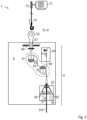
- Figure 2 shows the safety brake 9 and the braking element 91 each in a braking position.
- the braking element 91 is subjected to a storage force S upwards by a force accumulator (e.g. spring) 95 and is in contact with a support surface 92.
- a force accumulator e.g. spring
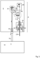
- Figure 3 shows the safety brake 9 and the braking element 91 each in a standby position in which no braking effect occurs.
- the standby position is when the cabin travels along the guide rail in normal operation.
- the upward displacement of the brake wedge is triggered by an actuator 94, as shown for example in the WO 2018/060751 A1
- the actuator 94 is connected to a Connector 96 is connected to the braking element 91.
- the movement of the connector in the release direction causes the braking element to move from the ready position to the braking position.
- the elevator car 5 can be driven by an auxiliary drive 7.
- the auxiliary drive 7 is used, for example, to recover the elevator car 5 if the main drive 6 is defective.
- the auxiliary drive has a recovery support 75, which can be a rope or belt, for example, and is driven by a recovery motor 71 and a drive pulley 72. In the event of a rescue, the recovery support 75 is connected to a recovery connection 55 of the elevator car 5.
- the recovery support 75 is not connected to the elevator car during normal operation.
- the recovery support 75 can be a support rope with a crane hook; the recovery connection 55 can comprise an eyelet into which the crane hook can engage.
- the eyelet itself can be designed to be removable.
- Figure 2 shows the recovery port 55 in a waiting state.
- Figure 3 shows the rescue connection 55 in a load state.
- the waiting state no load is transferred between the rescue connection 55 and the rescue support means 75; in particular, the waiting state always exists when no rescue support means is connected to the rescue connection 55.
- the rescue connection 55 in this example is brought into contact with a load stop 56 by applying force through the rescue support means 75.
- the elevator car 5 In the event of a rescue, the elevator car 5 should be recovered and thus moved, even if the safety brake was previously activated. To temporarily deactivate the safety brake 9, the elevator system 1 has a bridging arrangement 8.
- the bridging arrangement 8 comprises a bridging actuator 81 which is designed to apply a release force L to the safety brake 9.
- the release force L can counteract the storage force S of the energy storage device 95. As a result, the safety brake 9 is released and the car 5 can be towed.
- the first bridging actuator 81 is coupled to the recovery connection 55.
- a bridging sensor 82 is provided, which is designed to generate an actuating force B for the To provide actuating actuator 81.
- a bridging connection 83 is provided between the bridging sensor 82 and the bridging actuator 81.
- the bridging sensor 82 is operatively connected to the rescue connection 55 in such a way that the actuating force B is only provided when the rescue connection 55 is in the load state.
- the rescue connection 55 and the rescue support means are now at least partially loaded by the weight of the elevator car 5, which requires that the elevator car 5 is connected to the rescue support means 75.
- the recovery support is automatically returned to the standby state.
- the automatic return to the standby state can be carried out by a return spring 57 on the recovery connection or with the aid of a spring 95 of the safety brake 9 or the bridging arrangement.
- the bridging function is automatically canceled and the safety brake 9 is returned to the braking position.
- the safety brake 9 can therefore also serve as a safety brake during the recovery process.
- a limit value FG can also be set, from which the load state should occur for the load FL transferred to the recovery connection 55.
- the bridging arrangement is hydraulic.
- the bridging actuator 81 and the bridging sensor 82 are each formed by a hydraulic cylinder, which are connected to one another via a hydraulic line 83 as a bridging connection.
- the actuating force B and the release force L can be adjusted by selecting the bore cross-sections of the cylinders appropriately.
- the bridging arrangement is implemented with a cable pull.
- the bridging actuator has a lever arrangement, the dimensioning of which allows a ratio between the actuating force B and the release force L to be set. Otherwise, the structure and function correspond to the design according to the Figure 2 and 3 .
- the car may comprise a carriage and a cabin, as in the WO 2018/234211 A1
- the recovery connection can be provided on the cabin or the carriage, for example.
- the rescue support means 75 is designed as a tension support means.
- the rescue support means can also be designed as a push support means, in particular as a push rod.
- Figure 5 shows a corresponding design in the load state, as a modification of the design according to Figure 2 .
- the rescue support means 75 can be brought into engagement with the rescue connection 55, whereby the rescue connection 55 is transferred from the waiting state to the load state by the rescue support means 75 by means of a thrust application.
- Both the hydraulic bridging arrangement 8 according to the figure and the mechanical bridging arrangement according to the Figure 4 which may be slightly adjusted.
- the shear support according to Figure 5 can be a hydraulically driven push rod.
- the push-carrying means is connected to a separate vehicle 52 which can be moved in the shaft, in particular another cabin or a demand vehicle.
- the tension support means 75 can also be designed according to Figures 2 to 4 Instead of the auxiliary drive, it can be connected to a separate vehicle 52, which then tows the cabin.
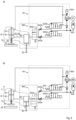
- Figure 6a shows a hydraulic circuit diagram of the car with the safety brake 9 in the braking state.
- the safety brake 9 has a braking element 91 (e.g. a brake disk) which is held in a braking position relative to the guide rail 22 by a spring force of a spring 95 ( Figure 6a ).
- a release actuator 97 in the form of a hydraulic cylinder can selectively generate a release force L ( Figure 6b ) and thus move the safety brake 9 and the braking element 91 from the braking position to the standby position.
- an actuator 94 is also provided which can hold the brake in the ready position.
- the actuator 94 comprises in particular a hydraulic arrangement.
- the actuator 94 has a hydraulic pump 941, which is driven, for example, by an electric motor M. Alternatively, the kinetic energy for driving the pump can also be taken from the driving movement of the cabin (similar to a bicycle dynamo).
- a valve arrangement 942 with switching valves 942a, b, c, throttle valves 942d, e and a check valve 942f is provided, by means of which the different operating states can be set.
- a pressure accumulator 943 is provided to keep the hydraulic medium under pressure so that the pump does not have to run continuously.
- the release actuator 97 is acted upon by the hydraulic medium in such a way that it provides the release force L against the storage force S of the spring 95.
- Figure 6a shows the arrangement in a braking state. Due to the position of the valves in the valve arrangement 942, the release actuator is not supplied with hydraulic medium in such a way that it cannot provide the required release force L. Therefore, the brake element 91 is acted upon by the spring 95 in the braking position.
- the release actuator is decoupled from the pressure accumulator 943 and the pump 941. Hydraulic medium in the release actuator can flow freely into a reservoir 944.
- the valves of the valve arrangement 942 are switched in such a way that the pressure accumulator 943 is connected to the release actuator 97.
- the two switching valves 942a,b are set in the other switching position than in Figure 6a shown.
- Figure 6b shows the arrangement in the loaded state.
- the recovery connection 55 is transferred to the loaded state.
- the braking element 91 or the brake 9 is actuated into the release position using a bridging arrangement 8,
- a hydraulic bridging sensor 82 in the form of a hydraulic cylinder is actuated, which pushes the release actuator 97 into the release position.
- the release actuator 97 therefore also represents the bridging actuator 81.
- the switching valve 942c prevents an unwanted outflow of hydraulic medium from the bridging actuator 81.
- FIG 7 shows an addition to the elevator system according to Figure 2 .
- the second rail system 27 runs along the side shaft wall 14b.
- a demand vehicle 52 in particular an emergency sled, can be moved along the rails 22.
- the winch 71 with which the traction support means 75 can be lowered to the elevator car 15, is arranged above the elevator car 15.
- a coupling hook 751 is arranged at the elevator car-side end of the traction support means 75, with which the traction support means 75 can be coupled to the rescue connection 55 of the elevator car 5.
- the elevator car 5 can be towed using the winch 71 (ie pulled up or lowered in the elevator shaft).
- the traction cable 73 can be coupled to the demand vehicle 29.
- the demand vehicle 52 has a guide device 752 which ensures at least a guidance of the tension support means 75 in the horizontal direction.
- the emergency carriage 29 thus serves as a guide system to guide the traction cable 73 with the coupling hook 75 to the defective elevator car 15. In principle, this design variant also possible to dispense with the second rail system 27 and to move the emergency carriage 29 along the first rail system 13.
Landscapes
- Maintenance And Inspection Apparatuses For Elevators (AREA)
Description
- Die
DE 10 2014 220 966 A1 offenbart eine Aufzugsanlage, in der mehrere Fahrkörbe zyklischen in einem Umlaufbetrieb, ähnlich einem Paternoster, betrieben werden. Im Unterschied zum klassischen Paternoster wird jeder Fahrkorb unabhängig von den anderen Fahrkörben angetrieben und kann somit unabhängig von den anderen Fahrkörben an jeder beliebigen Haltestelle anhalten. Umsetzeinheiten sind vorgesehen, um die Fahrkörbe aus einer vertikalen Fahrspur umzusetzen in eine horizontale Fahrspur, um so schließlich die Fahrkörbe zwischen unterschiedlichen vertikalen Fahrspuren umzusetzen. Der Antrieb erfolgt anhand eines Linearmotors. Diedeutsche Patentanmeldung 10 2019 200 665.5 beschreibt eine solche Aufzugsanlage, die alternativ mit einem Zahnstangenantrieb versehen ist.CN 109 987 472 A betrifft eine Aufzugsanlage, umfassend: einen Fahrkorb, der in einem Aufzugsschacht verfahrbar aufgenommen ist, eine Sicherheitsbremse, wobei die Sicherheitsbremse zwischen einer Bereitschaftsstellung und einer Bremsstellung überführbar ist, wobei die Sicherheitsbremse in der Bremsstellung einen Stillstand des Fahrkorbs bewirkt, und einen Hilfsantrieb mit einem Bergungstragmittel, eingerichtet zur temporären Lastübertragung mit einem Bergungsanschluss des Fahrkorbs. - Der Fahrkorb einer solchen Aufzugsanlage ist deutlich komplexer als der vorn herkömmlichen Aufzugsanlagen. Insofern sind Maßnahmen vorzusehen für den Fall, dass der Fahrkorb funktionsuntüchtig ist. In diesem Fall muss der Fahrkorb zügig aus dem Fahrspur entfernt werden, um den Betrieb der Aufzugsanlage mit den verbliebenen Fahrkörben aufrechtzuerhalten.
- Hierzu kommt ein Bergen des Fahrkorbs mit einem Hilfsantrieb in Betracht, um diese in einem Wartungsbereich zu überführen. Dabei ist allerdings zu berücksichtigen, dass im Bergungsfalls der funktionsuntüchtige Fahrkorb mit einer aktivierten Sicherheitsbrems im Schacht festgehalten wird.
- Die Sicherheitsbremse ist insbesondere dazu eingerichtet, den Fahrkorb in einem vertikalen Schacht bzw. in einer vertikalen Fahrspur festzusetzen.
- Es ist Aufgabe der vorliegenden Erfindung, die Funktionalität einer Aufzugsanlage der eingangs genannten Art zu verbessern. Diese Aufgabe wird gelöst durch eine Aufzugsanlage nach Anspruch 1; Ausgestaltungen sind Gegenstand der Unteransprüche sowie der Beschreibung.
- Die erfindungsgemäße Aufzugsanlage umfasst insbesondere: zumindest einen Fahrkorb, der insbesondere über einen Hauptantrieb entlang einer Fahrspur angetrieben wird. Die Aufzugsanlage umfasst eine Sicherheitsbremse, welche eingerichtet ist, den Fahrkorb abzubremsen. In einer Bereitschaftsstellung erlaubt die Sicherheitsbremse das Verfahren des Fahrkorbs entlang der Fahrspur; in einer Bremsstellung verhindert die Sicherheitsbremse das Verfahren entlang der Fahrspur.
- Die Erfindung ist insbesondere anwendbar bei Aufzugsanlagen mit einer Schachthöhe in erster, insbesondere vertikaler, Richtung von zumindest 100m, insbesondere zumindest 200m.
- Die Erfindung ist insbesondere anwendbar bei Aufzugsanlagen mit einer maximalen Fahrkorbgeschwindigkeit des Fahrkorbs in erster, insbesondere vertikaler, Richtung von zumindest 8 m/s, insbesondere zumindest 9 m/s oder 10 m/s.
- In einer Ausgestaltung umfasst die Sicherheitsbremse ein Bremselement, welches zwischen einer Bereitschaftsstellung und einer Bremsstellung überführbar ist. Insbesondere ist der Fahrkorb mittels Führungsrollen an zumindest einer Führungsschiene geführt; das Bremselement ist in dessen Bremsstellung mit einer der Führungsschienen in Reibkontakt.
- In einer Ausgestaltung wird das Bremselement nach initialer Betätigung durch einen Betätiger in die Bremsstellung überführt; anschließend wird das Bremselement anhand der Interaktion mit der Führungsschiene weiter in der Bremsstellung gehalten. Insbesondere ist die Sicherheitsbremse derart eingerichtet, dass ein Rückstellen des Betätigers während des Bremsvorgangs nicht zu einem Überführen des Bremselements aus der Bremsstellung herausführen kann.
- Der Betätiger kann in einer Ausgestaltung dazu eingerichtet sein, die Sicherheitsbremse auch zur Rückstellung aus der Bremsstellung in die Bereitschaftsstellung zu überführen. Bei einer solchen Ausgestaltung ist es möglich, dass ein Überbrückungsaktuator der Überbrückungsanordnung zugleich auch den Freigabeaktuator der Sicherheitsbremse darstellt. Insbesondere ist die Sicherheitsbremse derart eingerichtet, dass die Aktivierung zwangläufig zu einem Stillstand des Fahrkorbs führt, insbesondere zur Vermeidung eines Unglücks. Insofern ist die Sicherheitsbremse grundsätzlich von einer Betriebsbremse zu unterscheiden, welche eingerichtet ist, während des Betriebs die Geschwindigkeit kurzfristig zu reduzieren oder den Fahrkorb während eines Stockwerkaufenthalts fest in der Halteposition zu fixieren.
- Die Erfindung ist insbesondere anwendbar bei Aufzugsanlagen mit mehreren Fahrspuren mit jeweils zugeordneten Führungsschienen, mit zumindest einer Umsetzanordnung, welche zum Überführen des Fahrkorbs von einer ersten Fahrspur auf eine zweite Fahrspur eingerichtet ist. Insbesondere umfasst die Umsetzanordnung zumindest eine bewegbare, insbesondere drehbare Führungsschiene; insbesondere ist die bewegbare Zahnstange synchron mit einer der bewegbaren Führungsschienen bewegbar.
- In einer Ausgestaltung wird bedarfsweise eine Lösekraft auf die Sicherheitsbremse aufgebracht. Die Lösekraft ist insbesondere derart dimensioniert, dass die Sicherheitsbremse aus der Bremsstellung in die Bereitschaftsstellung überführt wird.
- Der Fahrkorb wird insbesondere durch einen Linearantrieb als Hauptantrieb angetrieben.
- Das Bergungstragmittel ist insbesondere ein Bergungszugtragmittel. Das Bergungstragmittel ist insbesondere ein Tragseil oder ein Tragriemen. Alternativ kann das Bergungstragmittel ein Bergungsschubtragmittel sein, insbesondere eine Verbindungsstange.
- Insbesondere ist das Bergungstragmittel während einer Normalfunktion des Hauptantriebs außer Funktion und dient zum Tragen des Fahrkorbs im Falle eines Defekts des Hauptantriebs.
- Sollte in einem Fall die Überbrückungsanordnung einen Defekt aufweisen, so wird die Überbrückungsfunktion sofort aufgehoben. Dies kann eintreten, wenn beispielsweise eine Hydraulikleitung ein Leck aufweist. Dann kann selbst im Lastzustand die Sicherheitsbremse wieder in die Bremsstellung überführt werden, um einen sicheren Zustand herbeizuführen.
- In einer Ausgestaltung umfasst der Hilfsantrieb eine angeordnete Winde mit einem Zugseil. Es ist als Bedarfsfahrzeug insbesondere ein Notfallschlitten, mit dem Bergungstragmittel koppelbar, um das Zugseil zumindest während des Herablassens zu führen. Am herablassbaren Ende des Zugseils ist dabei insbesondere eine Kopplungshaken angeordnet, mit dem das Zugseil an den Fahrkorb gekoppelt werden kann. Das Bedarfsfahrzeug kann über den Linearantrieb verfahren werden.
- Diese Ausgestaltung hat den Vorteil, dass ein Fahrkorb problemlos abgeschleppt werden kann, wobei die Gewichtskraft des Fahrkorbs während des Abschleppvorgangs über das Zugseil und die Winde übertragen wird. Im Gegensatz zu einer Variante, bei der der Fahrkorb mit einer oberhalb des Fahrkorbs angeordneten Winde abgeschleppt wird, ohne das ein Notfallschlitten zum Einsatz kommt, besteht hier nicht das Risiko, dass das Zugseil beim Herablassen zum defekten Fahrkorb zu schwingen beginnt. Somit werden zum einen Beschädigungen von Komponenten im Aufzugschacht bei Zusammenstößen mit einem frei schwingenden Kopplungshaken am Ende des Zugseils vermieden. Zum anderen ist sichergestellt, dass der Kopplungshaken an einer wohldefinierten Position den Fahrkorb erreicht. Folglich kann der Kopplungshaken problemlos an einem Kopplungsglied des Fahrkorbs angreifen. Der Notfallschlitten dient also lediglich als ein Führungssystem, um das Zugseil mit dem Kopplungshaken gezielt zum defekten Fahrkorb zu führen. Grundsätzlich ist es bei dieser Ausführungsvariante ebenfalls möglich, auf das zweite Schienensystem zu verzichten und den Notfallschlitten entlang des ersten Schienensystems zu verfahren.
- Die Erfindung wird nachfolgend anhand der Figuren näher erläutert. Es zeigt jeweils schematisch
- Figur 1
- ausschnittsweise eine erfindungsgemäße Aufzugsanlage in perspektivischer Darstellung;
- Figur 2
- Details des Fahrkorbs der Aufzugsanlage nach
Figur 1 mit aktivierter Sicherheitsbremse; - Figur 3
- den Fahrkorb der Aufzugsanlage nach
Figur 1 während einer Bergungssituation; - Figur 4
- den Fahrkorb der Aufzugsanlage nach
Figur 1 in einer weiteren Ausgestaltung während einer Bergungssituation; - Figur 5
- den Fahrkorb der Aufzugsanlage nach
Figur 1 in einer weiteren Ausgestaltung während einer Bergungssituation; - Figur 6
- den Fahrkorb der Aufzugsanlage nach
Figur 1 in einer weiteren Ausgestaltung a) während eines Bremszustandes, b) während einer Bergungssituation; - Figur 7
- eine Weiterbildung der Aufzugsanlage nach
Figur 2 . - Die
Figuren 1 zeigt Teile einer erfindungsgemäßen Aufzugsanlage 1. Die Aufzugsanlage 1 umfasst eine Mehrzahl an Fahrspuren 2H, 2VL, 2VR entlang welcher mehrere Fahrkörbe 5 geführt sind. - Es sind mehrere, hier beispielhaft zwei, vertikale Fahrspuren 2VL, 2VR in einer ersten Richtung z ausgerichtet, entlang welcher der Fahrkorb 5 zwischen unterschiedlichen Stockwerken verfahrbar ist. Zwischen den beiden vertikalen Fahrschienen 2VL, 2VR sind horizontale Fahrspuren 2H in einer zweiten Richtung y angeordnet, entlang welcher der Fahrkorb 5 jeweils innerhalb eines Stockwerks verfahrbar ist. Ferner verbindet die horizontale Fahrspur 2H die beiden vertikalen Fahrspuren 2VL, 2VR miteinander. Somit dient die horizontale Fahrspur 2H auch zum Überführen des Fahrkorbs 5 zwischen den beiden vertikalen Fahrspuren 2VL, 2VR, um z.B. einen modernen Paternoster-Betrieb auszuführen. Es sind in der Aufzugsanlage 1 noch weitere solcher horizontalen Fahrspuren 2H vorgesehen, welche die beiden vertikalen Fahrschienen miteinander verbinden. Ferner können weitere vertikale Fahrspuren vorgesehen sein, die nicht dargestellt sind.
- Entlang der Fahrspuren sind Führungsschienen 22V, 22H, 22B zur Führung der Fahrkörbe vorgesehen. Die Fahrkörbe 5 weisen zur Führung an den Führungsschienen Führungsrollen 51 auf.
- Über eine Umsetzanordnung 3 mit zwei Umsetzeinheiten 30ist jeweils der Fahrkorb 5 überführbar zwischen einer der vertikalen Führungsschiene 2VR, 2VL und der horizontalen Führungsschiene 22H und7oder zwischen zwei vertikalen Führungsschienen. Eine
- Umsetzeinheit 30 weist eine bewegbare Führungsschiene 22B auf, welche im vorliegenden Fall drehbar ist.
- Die Aufzugsanlage weist einen Hauptantrieb 6 auf, durch den der Fahrkorb während eines Normalbetriebs angetrieben wird. Der Hauptantrieb 6 ist insbesondere als Linearantrieb ausgebildet und weist im Aufzugschacht angebrachte Statoren 61 und am Fahrkorb 5 angebrachte Läufer 62 auf.
- Im vorliegenden Ausführungsbeispiel ist die vertikale Richtung sowie die horizontale Richtung lediglich ein Beispiel für eine erste bzw. zweite Richtung.
- Sämtliche Führungsschienen sind zumindest mittelbar in einer Schachtwand installiert. Bis hierin entspricht die Aufzugsanlage dem Grunde nach dessen, was in der
WO 2015/144781 A1 sowie in denDE10 2016 211 997A1 undDE 10 2015 218 075 A1 beschrieben ist. - Anhand der weiteren Figuren werden Details am Fahrkorb näher beschrieben. Die vorliegende Erfindung verwendet eine Sicherheitsbremse 9, welche im Notfall den Fahrkorb 5 zum Stillstand bringen kann Die Sicherheitsbremse 9 umfasst ein Bremselement 91, hier beispielhaft in Form eines Bremskeils 91, welches beweglich in einem Gehäuse 93 gehalten ist.
Figur 2 zeigt die Sicherheitsbremse 9 und das Bremselement 91 jeweils in einer Bremsstellung. Dabei ist das Bremselement 91 durch einen Kraftspeicher (z.B. Feder) 95 mit einer Speicherkraft S nach oben beaufschlagt und in Anlage mit einer Stützfläche 92. Dadurch wird das Bremselement in Richtung der vertikalen Führungsschiene 22V beaufschlagt und gerät folglich mit dieser in reibenden Kontakt. Es entsteht so eine Verkeilung zwischen dem Bremselement 91 und der Führungsschiene 22V, was einen Nothalt des Fahrkorbs 5 zur Folge hat. Beispielhaft und lediglich optional umfasst die Ausgestaltung derFigur 2 zwei solcher Bremselemente 91, die an gegenüberliegenden Seiten der Führungsschiene angeordnet sind. - Zum Vergleich:
Figur 3 zeigt die Sicherheitsbremse 9 und das Bremselement 91 jeweils in einer Bereitschaftsstellung, in der keine Bremswirkung erfolgt. Die Bereitschaftsstellung liegt vor, wenn die Kabine im normalen Betrieb entlang der Führungsschiene fährt. - Die Verlagerung des Bremskeils nach oben wird ausgelöst durch einen Betätiger 94, wie dieser beispielsweise in der
WO 2018/060751 A1 beschrieben ist. Der Betätiger 94 ist über einen Verbinder 96 mit dem Bremselement 91 verbunden. Die Bewegung des Verbinders in Auslöserichtung bewirkt die Bewegung des Bremselements aus der Bereitschaftsstellung in die Bremsstellung. - Falls erforderlich kann der Fahrkorb 5 über einen Hilfsantrieb 7 angetrieben werden. Der Hilfsantrieb 7 wird beispielsweise zum Bergen des Fahrkorbs 5 eingesetzt, wenn der Hauptantrieb 6 einen Defekt aufweist. Der Hilfsantrieb weist ein Bergungstragmittel 75 auf, was z.B. ein Seil oder Riemen sein kann, und über einen Bergungsmotor 71 und eine Treibschreibe 72 angetrieben wird. Das Bergungstragmittel 75 wird im Bergungsfall mit einem Bergungsanschluss 55 des Fahrkorbs 5 verbunden. Das Bergungstragmittel 75 ist im Normalbetrieb nicht mit dem Fahrkorb verbunden. Das Bergungstragmittel 75 kann ein Tragseil mit einem Kranhaken sein; der Bergungsanschluss 55 kann eine Öse umfassen, in welche der Kranhaken eingreifen kann. Die Öse selbst kann abnehmbar ausgebildet sein.
-
Figur 2 zeigt den Bergungsanschluss 55 in einem Wartezustand.Figur 3 zeigt den Bergungsanschluss 55 in einem Lastzustand. Im Wartezustand erfolgt keine Lastübertragung zwischen dem Bergungsanschluss 55 und dem Bergungstragmittel 75; insbesondere liegt der Wartezustand immer dann vor, wenn am dem Bergungsanschluss 55 kein Bergungstragmittel angeschlossen ist. Zur Überführung des Bergungsanschlusses 55 aus dem Wartezustand in den Lastzustand wird der Bergungsanschlusses 55 in diesem Beispiel durch Kraftbeaufschlagung durch das Bergungstragmittel 75 in Anlage mit einem Lastanschlag 56 gebracht. - Im Bergungsfall soll der Fahrkorb 5 geborgen werden und damit bewegt werden, auch wenn die Sicherheitsbremse zuvor aktiviert wurde. Zur temporären Inaktivierung der Sicherheitsbremse 9 weist die Aufzugsanlage 1 eine Überbrückungsanordnung 8 auf.
- Die Überbrückungsanordnung 8 umfasst einen Überbrückungsaktuator 81 auf, welcher eingerichtet ist, eine Lösekraft L auf die Sicherheitsbremse 9 aufzubringen. Die Lösekraft L kann der Speicherkraft S des Kraftspeichers 95 entgegenwirken. Dadurch wird die Sicherheitsbremse 9 gelöst und der Fahrkorb 5 kann abgeschleppt werden.
- Der erste Überbrückungsaktuator 81 ist dabei an den Bergungsanschluss 55 gekoppelt. Hierzu ist ein Überbrückungsgeber 82 vorgesehen, der eingerichtet ist, eine Betätigungskraft B für den Betätigungsaktuator 81 bereitzustellen. Dazu ist zwischen dem Überbrückungsgeber 82 und dem Überbrückungsaktuator 81 eine Überbrückungsverbindung 83 vorgesehen.
- Der Überbrückungsgeber 82 ist dabei derart mit dem Bergungsanschluss 55 wirkverbunden, so dass die Betätigungskraft B nur bereitgestellt wird, wenn der Bergungsanschluss 55 im Lastzustand ist. In diesem Fall wird nun der Bergungsanschluss 55 und das Bergungstragmittel zumindest teilweise durch das Gewicht des Fahrkorbs 5 belastet, was voraussetzt, dass der Fahrkorb 5 an dem Bergungstragmittel 75 angeschlossen ist.
- Sollte die Betätigungskraft entfallen (z.B. durch Unterbrechung der Überbrückungsverbindung oder durch Riss des Bergungstragmittels), wird automatisch die Bergungsaufnahme automatisch wieder in den Wartezustand überführt. Die automatische Rücküberführung in den Wartezustand kann durch eine Rückstellfeder 57 am Bergungsanschluss oder mithilfe einer Feder 95 der Sicherheitsbremse 9 oder der Überbrückungsanordnung erfolgen. Es entfällt automatisch die Überbrückungsfunktion und die Sicherheitsbremse 9 wird wieder zurück in die Bremsstellung überführt. Somit kann die Sicherheitsbremse 9 auch während des Bergungsvorgangs als Sicherheitsbremse dienen. Mithilfe der Rückstellfeder 57 und/oder der anderen Federn kann auch ein Grenzwert FG eingestellt werden, ab welcher der am Bergungsanschluss 55 übertragenen Last FL der Lastzustand eintreten soll.
- In dem Ausführungsbeispiel nach
Figuren 2 und3 ist die Überbrückungsanordnung hydraulisch ausgebildet. Der Überbrückungsaktuator 81 und der Überbrückungsgeber 82 ist jeweils durch einen Hydraulikzylinder ausgebildet, die über eine Hydraulikleitung 83 als Überbrückungsverbindung miteinander verbunden sind. Durch geeignete Wahl der Bohrungsquerschnitte der Zylinder kann die Betätigungskraft B sowie die Lösekraft L eingestellt werden. - In dem Ausführungsbeispiel nach
Figur 4 ist die Überbrückungsanordnung mit einem Seilzug realisiert. Der Überbrückungsaktuator weist dabei eine Hebelanordnung auf, durch deren Dimensionierung eine Übersetzung zwischen der Betätigungskraft B und der Lösekraft L eingestellt werden kann. Im Übrigen entspricht der Aufbau und die Funktion der Ausgestaltung nach derFigur 2 und3 . - Der Fahrkorb kann einen Fahrschlitten und eine Kabine umfassen, wie beispielsweise in der
WO 2018/234211 A1 beschrieben ist. Der Bergungsanschluss kann z.B. an der Kabine oder dem Fahrschlitten vorgesehen sein. - In den
Figuren 2 bis 4 ist das Bergungstragmittel 75 als Zugtragmittel ausgebildet. Gleichsam kann das Bergungstragmittel auch als Schubtragmittel ausgebildet sein, insbesondere als Schubstange.Figur 5 zeigt eine entsprechende Ausgestaltung im Lastzustand, als Abwandlung der Ausgestaltung nachFigur 2 . Der Bergungstragmittel 75, kann hier in Eingriff gebracht werden mit dem Bergungsanschluss 55, wobei durch eine Schubbeaufschlagung der Bergungsanschluss 55 durch das Bergungstragmittel 75 aus dem Wartezustand in den Lastzustand überführt wird. Die weitere Funktion ist dann derart wie oben beschrieben. Es kann sowohl die hydraulische Überbrückungsanordnung 8 nach der Figur als auch die mechanische Überbrückungsanordnung nach derFigur 4 verwendet werden, die jeweils geringfügig anzupassen sind. - Das Schubtragmittel nach
Figur 5 kann eine hydraulisch angetriebene Schubstange sein. In einer Ausgestaltung ist das Schubtragmittel verbunden mit einem separaten Fahrzeug 52, welches in dem Schacht verfahrbar ist, insbesondere eine andere Kabine oder ein Bedarfsfahrzeug. - Analog kann auch das Zugtragmittel 75 in den Ausgestaltungen nach
Figuren 2 bis 4 anstelle des Hilfsantriebs an ein separates Fahrzeug 52 angeschlossen sein, welches die Kabine dann ziehend abschleppt. - Eine weitere Ausgestaltung wird anhand der
Figuren 6a und 6b beschrieben.Figur 6a zeigt einen Hydraulikschaltplan des Fahrkorbs mit der Sicherheitsbremse 9 im Bremszustand. Die Sicherheitsbremse 9 weist hierbei ein Bremselement 91 (z.B. eine Bremsscheibe) auf, welches durch eine Federkraft einer Feder 95 in einer Bremsstellung relativ zur Führungsschiene 22 gehalten wird (Figur 6a ). Ein Freigabeaktuator 97 in Form eines Hydraulikzylinders kann selektiv eine der Federkraft S entgegenwirkende Lösekraft L (Figur 6b ) bereitstellen und so die Sicherheitsbremse 9 und das Bremselement 91 aus der Bremsstellung in die Bereitschaftsstellung überführen. - Auch bei dieser Ausgestaltung ist ein Betätiger 94 vorgesehen, der die Bremse in der Bereitschaftsstellung halten kann. Der Betätiger 94 umfasst insbesondere eine Hydraulikanordnung.
- Der Betätiger 94 weist eine Hydraulikpumpe 941 auf, die z.B. durch einen Elektromotor M angetrieben ist. Alternativ kann die Bewegungsenergie zum Antreiben der Pumpe auch aus der Fahrbewegung der Kabine abgegriffen werden (analog Fahrraddynamo). Eine Ventilanordnung 942 mit Schaltventilen 942a,b,c, Drosselventilen 942d,e sowie einem Rückschlagventil 942f ist vorgesehen, anhand der die unterschiedlichen Betriebszustände eingestellt werden können. Ein Druckspeicher 943 ist vorgesehen, um das Hydraulikmedium unter Druck zu halten, so dass die Pumpe nicht ständig laufen muss. Der Freigabeaktuator 97 wird durch das Hydraulikmedium derart beaufschlagt, dass dieser die Lösekraft L entgegen der Speicherkraft S der Feder 95 bereitstellt.
-
Figur 6a zeigt die Anordnung in einem Bremszustand. Durch die Stellung der Ventile in der Ventilanordnung 942 ist der Freigabeaktuator nicht derart mit Hydraulikmedium beaufschlagt, so dass dieser die erforderliche Lösekraft L nicht bereitstellen kann. Daher wird das Bremselement 91 durch die Feder 95 in die Bremsstellung beaufschlagt. Der Freigabeaktuator ist dabei vom Druckspeicher 943 und der Pumpe 941 entkoppelt. Hydraulikmedium im Freigabeaktuator kann frei in ein Reservoir 944 abfließen. In der Bereitschaftsstellung (nicht dargestellt) sind die Ventile der Ventilanordnung 942 derart geschaltet, dass der Druckspeicher 943 mit dem Freigabeaktuator 97 verbunden ist. Insbesondere sind dabei die beiden Schaltventile 942a,b in der jeweils anderen Schaltstellung gestellt als inFigur 6a dargestellt. -
Figur 6b zeigt die Anordnung im Lastzustand. Dabei ist der Bergungsanschluss 55 in den Lastzustand überführt. Es wird gleichermaßen wie in den vorherigen Ausgestaltungen anhand einer Überbrückungsanordnung 8 das Bremselement 91 bzw. die Bremse 9 in die Freigabestellung beaufschlagt, - Ein hydraulischer Überbrückungsgeber 82 in Form eines Hydraulikzylinders wird dabei betätigt, welcher den Freigabeaktuator 97 in die Freigabestellung beaufschlagt. Der Freigabeaktuator 97 stellt folglich gleichermaßen den Überbrückungsaktuator 81 dar. Das Schaltventil 942c verhindert dabei einen ungewollten Abfluss von Hydraulikmedium von dem Überbrückungsaktuator 81.
- Auch in dieser Ausgestaltung ist die Sicherheit während des Abschleppvorgangs gewährleistet. Sollte eine Fehlfunktion entweder des Betätigers 94 oder der Überbrückungsanordnung 8 auftreten so entfällt der Druck im Hydraulikmedium am Freigabeaktuator 97 bzw. Überbrückungsaktuator 81 und damit die Lösekraft. Die Feder 95 kann sodann das Bremselement wieder in die Bremsstellung überführen.
- In der
Figur 6 ist die Anordnung mit einem Schubtragmittel gezeigt. Alternativ ist diese Anordnung bei geringfügiger Umgestaltung (vergleicheFigur 5 mitFigur 2 ) auch bei Verwendung eines Zugtragmittels möglich. -
Figur 7 zeigt eine Ergänzung der Aufzugsanlage nachFigur 2 . An der seitlichen Schachtwand 14b verläuft das zweite Schienensystem 27. Entlang der Schienen 22 ist ein Bedarfsfahrzeug 52 insbesondere ein Notfallschlitten bewegbar. Oberhalb des Fahrkorbs 15 ist die Winde 71 angeordnet, mit der das Zugtragmittel 75 zum Fahrkorb 15 herabgelassen werden kann. Am fahrkorbseitigen Ende des Zugtragmittels 75 ist ein Kopplungshaken 751 angeordnet, mit dem das Zugtragmittels 75 an den Bergungsanschluss 55 des Fahrkorbs 5 gekoppelt werden kann. Im angekoppelten Zustand kann der Fahrkorb 5 mittels der Winde 71 abgeschleppt werden (d.h. im Aufzugschacht nach oben gezogen oder herabgelassen werden). Um zu verhindern, dass das Zugtragmittel beim Herunterlassen zum Fahrkorb 5 zu schwingen beginnt, ist das Zugseil 73 mit dem Bedarfsfahrzeug 29 koppelbar. Dazu weist das Bedarfsfahrzeug 52 eine Führungseinrichtung 752 auf, die zumindest eine Führung des Zugtragmittels 75 in horizontaler Richtung gewährleistet. - Somit werden zum einen Beschädigungen von Komponenten im Aufzugschacht 21 bei Zusammenstößen mit einem frei schwingenden Kopplungshaken 75 am Ende des Zugseils 73 vermieden. Zum anderen ist sichergestellt, dass der Kopplungshaken 751 an einer wohldefinierten Position den Fahrkorb 15 erreicht. Folglich kann der Kopplungshaken 75 problemlos an einem Kopplungsglied 67 des Fahrkorbs 15 angreifen. Der Notfallschlitten 29 dient also als ein Führungssystem, um das Zugseil 73 mit dem Kopplungshaken 75 gezielt zum defekten Fahrkorb 15 zu führen. Grundsätzlich ist es bei dieser Ausführungsvariante ebenfalls möglich, auf das zweite Schienensystem 27 zu verzichten und den Notfallschlitten 29 entlang des ersten Schienensystems 13 zu verfahren.
-
- 1
- Aufzugsanlage
- 2H
- horizontale Fahrspur
- 2VL, 2VR
- vertikale Fahrspur
- 22V
- feste Führungsschiene vertikal
- 22H
- feste Führungsschiene horizontal
- 22B
- bewegbare Führungsschiene
- 75
- Bergungstragmittel
- 3
- Umsetzanordnung
- 30
- Umsetzeinheit
- 4
- Aufzugsschacht
- 5
- Fahrkorb
- 51
- Führungsrollen
- 52
- separates Fahrzeug
- 527
- Führungseinrichtung
- 55
- Bergungsanschluss
- 56
- Lastanschlag
- 57
- Rückstellfeder
- 6
- Hauptantrieb
- 61
- Stator
- 62
- Läufer
- 7
- Hilfsantrieb
- 71
- Bergungsmotor
- 72
- Treibschreibe
- 75
- Bergungstragmittel
- 751
- Kopplungshaken
- 8
- Überbrückungsanordnung
- 81
- Überbrückungsaktuator
- 82
- Überbrückungsgeber
- 83
- Überbrückungsverbindung
- 9
- Sicherheitsbremse
- 91
- beweglicher Bremskeil
- 92
- Stützfläche
- 93
- Bremsgehäuse
- 94
- Betätiger
- 941
- Pumpe
- 942
- Ventilanordnung
- 942a-c
- Schaltventile
- 942d-e
- Drosselventil
- 942f
- Rückschlagventil
- 944
- Reservoir
- 95
- Feder
- 96
- Verbinder
- 97
- Freigabeaktuator
- S
- Speicherkraft
- L
- Lösekraft
- B
- Betätigungskraft
- FL
- übertragende Last
- FG
- Grenzwert
Claims (19)
- Aufzugsanlage (1), umfassend:einen Fahrkorb (5), der in einem Aufzugsschacht (4) verfahrbar aufgenommen ist, undinsbesondere über ein Hauptantrieb (6) angetrieben wird,eine Sicherheitsbremse (9), wobei die Sicherheitsbremse (9) zwischen einer Bereitschaftsstellung und einer Bremsstellung überführbar ist, wobei die Sicherheitsbremse in der Bremsstellung einen Stillstand des Fahrkorbs (5) bewirkt,ein Hilfsantrieb (7) mit einem Bergungstragmittel (75), insbesondere Bergungszugtragmittel oder Bergungsschubtragmittel, eingerichtet zur temporären Lastübertragung mit einem Bergungsanschluss (55) des Fahrkorbs (5),dadurch gekennzeichnet,dass die Aufzugsanlage (1) eingerichtet ist, dass in Abhängigkeit eines Betriebszustandes des Bergungsanschlusses (55) die Sicherheitsbremse (9) aus der Bremsstellung in die Bereitschaftsstellung überführt wird.
- Aufzugsanlage (1) nach dem vorherigen Anspruch,
dadurch gekennzeichnet,dass der Bergungsanschluss (55) zwischen zumindest zwei Betriebszuständen, nämlich einem Wartezustand und einem Lastzustand, überführbar ist,wobei im Lastzustand die Gewichtskraft des Fahrkorbs (5) zumindest teilweise, insbesondere oberhalb eines Grenzwertes, über den Bergungsanschluss (55) auf das Bergungstragmittel (75) übertragen wird. - Aufzugsanlage (1) nach dem vorherigen Anspruch,
dadurch gekennzeichnet,dass der Wartezustand dann vorliegt,wenn der Bergungsanschluss (55) vom Bergungstragmittel (75) getrennt ist, und/oderwenn die über den Bergungsanschluss (55) auf das Bergungstragmittel (75) übertragene Last (FL) unterhalb eines vorbestimmten Grenzwertes (FG) liegt. - Aufzugsanlage (1) nach einem der vorherigen Ansprüche,
dadurch gekennzeichnet,dass funktionell zwischen dem Bergungsanschluss (55) und der Sicherheitsbremse (9) eine Überbrückungsanordnung (8) angeordnet ist,wobei die Überbrückungsanordnung (9) eingerichtet ist, in Abhängigkeit des Betriebszustandes des Bergungsanschlusses (55) eine Lösekraft (L) auf die Sicherheitsbremse aufzubringen. - Aufzugsanlage (1) nach dem vorherigen Anspruch und Anspruch 2,
dadurch gekennzeichnet,
dass die Überbrückungsanordnung (8) eingerichtet ist, die Lösekraft (L) bereitzustellen, wenn der Bergungsanschluss (55) im Lastzustand ist. - Aufzugsanlage (1) nach Anspruch 4 oder 5,
dadurch gekennzeichnet,
dass die Überbrückungsanordnung (8) einen Überbrückungsaktuator (81) und einen Überbrückungsgeber (82) aufweist. - Aufzugsanlage (1) nach dem vorherigen Anspruch,
dadurch gekennzeichnet,
dass der Überbrückungsgeber (82) eingerichtet ist, eine Betätigungskraft (B) für den Überbrückungsaktuator (81) in Abhängigkeit des Betriebszustandes des Bergungsanschlusses (55) bereitzustellen, insbesondere falls der Bergungsanschluss (55) im Lastzustand ist,- wobei der Überbrückungsaktuator (81) eingerichtet ist, bei Vorliegen der Betätigungskraft (B) eine Lösekraft (L) für die Sicherheitsbremse (9) bereitzustellen. - Aufzugsanlage (1) nach einem der Ansprüche 4 bis 7,
dadurch gekennzeichnet,
dass Aufzugsanlage eingerichtet ist, die Sicherheitsbremse (9) während des Lastzustand in die Bremsstellung zu überführen und in der Bremsstellung zu belassen, falls die Überbrückungsanordnung (9) einen Defekt aufweist. - Aufzugsanlage (1) nach einem der vorherigen Ansprüche,
dadurch gekennzeichnet,dass die Sicherheitsbremse (9) ein Bremselement (91) umfasst, welches zwischen einer Bereitschaftsstellung und einer Bremsstellung überführbar ist,insbesondere dass das Bremselement (91) nach initialer Betätigung durch einen Betätiger (94) in die Bremsstellung überführt wird und anschließend durch die Interaktion mit einer Führungsschiene (22) weiter in der Bremsstellung gehalten wird. - Aufzugsanlage (1) nach einem der vorherigen Ansprüche,
dadurch gekennzeichnet,
dass das Bergungstragmittel ein Zugtragmittel ist, insbesondere eine Tragseil oder ein Tragriemen. - Aufzugsanlage (1) nach einem der Ansprüche 1 bis 9,
dadurch gekennzeichnet,
dass das Bergungstragmittel ein Schubtragmittel ist, insbesondere eine Verbindungsstange. - Aufzugsanlage (1) nach einem der vorherigen Ansprüche,
dadurch gekennzeichnet,
dass der Fahrkorb einen Betätiger (94) umfasst, wobei der Betätiger (94) zum Überführen der Sicherheitsbremse (9) aus der Bereitschaftsstellung und in Bremsstellung eingerichtet ist. - Aufzugsanlage (1) nach dem vorherigen Anspruch,
dadurch gekennzeichnet,
dass der Betätiger (94) zum Überführen der Sicherheitsbremse (9) aus der Bremsstellung in die Bereitschaftsstellung eingerichtet ist. - Aufzugsanlage (1) nach dem vorherigen Anspruch,
dadurch gekennzeichnet,
dass die Sicherheitsbremse (9) einen Freigabeaktuator (97) umfasst, welcher eingerichtet ist, nach Betätigung durch den Betätiger (94) das Bremselement (91) aus der Bremsstellung in die Bereitschaftsstellung zu überführen. - Aufzugsanlage (1) nach dem vorherigen Anspruch und Anspruch 6 oder 7,
dadurch gekennzeichnet,
dass der Überbrückungsaktuator (81) den Freigabeaktuator (97) ausbildet. - Aufzugsanlage (1) nach dem vorherigen Anspruch,
dadurch gekennzeichnet,
dass die Sicherheitsbremse (9) eingerichtet ist, durch hydraulische Betätigung und/oder durch mechanische Betätigung aus der Bremsstellung in die Bereitschaftsstellung überführt zu werden. - Aufzugsanlage (1) nach einem der vorherigen Ansprüche,
dadurch gekennzeichnet,
dass das Bergungstragmittel (55) ein Zugtragmittel ist, welches von oben an dem Fahrkorb (5) anbringbar ist, wobei ein Bedarfsfahrzeug (52) vorgesehen ist, welches im Aufzugsschacht bewegbar ist und eingerichtet ist, das Zugtragmittel bei dessen Bewegung auf den Fahrkorb zumindest in horizontaler Richtung zu führen. - Aufzugsanlage (1) nach einem der vorherigen Ansprüche, umfassend mehrere Fahrspuren mit jeweiligen Führungsschienen (2VL, 2VR, 2H), zumindest eine Umsetzanordnung (3), welche eingerichtet ist zum Überführen des Fahrkorbs von einer ersten Fahrspur auf eine zweite Fahrspur,
insbesondere umfasst die Umsetzanordnung (3) zumindest eine bewegbare, insbesondere drehbare Führungsschiene (22B). - Verfahren zum Bergen eines Fahrkorbs einer Aufzugsanlage nach einem der vorherigen Ansprüche, wobei in einer Bergungssituation der Fahrkorb fahruntüchtig ist, insbesondere ist der Hauptantrieb nicht in der Lage, den Fahrkorb zu verfahren, und wobei in der Bergungssituation die Sicherheitsbremse in der Bremsstellung ist; das Verfahren umfasst die folgenden Verfahrensschritte:Bereitstellen eines Hilfsantriebs (6),nach Eintritt der Bergungssituation Verbinden des Hilfsantriebs (6) mit dem Bergungsanschluss des Fahrkorb (5),wobei in Abhängigkeit eines Betriebszustandes des Bergungsanschlusses die Sicherheitsbremse aus der Bremsstellung in die Freigabestellung überführt wird.
Applications Claiming Priority (2)
| Application Number | Priority Date | Filing Date | Title |
|---|---|---|---|
| DE102020115998.6A DE102020115998A1 (de) | 2020-06-17 | 2020-06-17 | Aufzugsanlage |
| PCT/EP2021/066047 WO2021254997A1 (de) | 2020-06-17 | 2021-06-15 | Aufzugsanlage |
Publications (2)
| Publication Number | Publication Date |
|---|---|
| EP4168344A1 EP4168344A1 (de) | 2023-04-26 |
| EP4168344B1 true EP4168344B1 (de) | 2024-07-31 |
Family
ID=76584488
Family Applications (1)
| Application Number | Title | Priority Date | Filing Date |
|---|---|---|---|
| EP21734079.3A Active EP4168344B1 (de) | 2020-06-17 | 2021-06-15 | Aufzugsanlage |
Country Status (5)
| Country | Link |
|---|---|
| EP (1) | EP4168344B1 (de) |
| CN (1) | CN115697878A (de) |
| DE (1) | DE102020115998A1 (de) |
| FI (1) | FI4168344T3 (de) |
| WO (1) | WO2021254997A1 (de) |
Families Citing this family (1)
| Publication number | Priority date | Publication date | Assignee | Title |
|---|---|---|---|---|
| EP4688633A1 (de) * | 2023-03-27 | 2026-02-11 | Inventio Ag | Bremssystem |
Family Cites Families (19)
| Publication number | Priority date | Publication date | Assignee | Title |
|---|---|---|---|---|
| CH695244A5 (de) * | 2001-12-12 | 2006-02-15 | Yung Hsin Chen | Notfallfahrvorrichtung für Aufzüge. |
| US7316297B2 (en) * | 2005-05-27 | 2008-01-08 | Chiu Nan Wang | Elevator escape device |
| MY189516A (en) * | 2014-01-23 | 2022-02-16 | Inventio Ag | Method and mechanism for releasing hydraulic elevator brakes |
| DE102014104458A1 (de) | 2014-03-28 | 2015-10-01 | Thyssenkrupp Elevator Ag | Aufzugsystem |
| DE102014220966A1 (de) | 2014-10-16 | 2016-04-21 | Thyssenkrupp Elevator Ag | Verfahren zum Betreiben einer Transportanlage sowie entsprechende Transportanlage |
| EP3331799A1 (de) | 2015-08-03 | 2018-06-13 | Otis Elevator Company | Zwischenübergabestation |
| DE102015218075A1 (de) | 2015-09-21 | 2017-03-23 | Thyssenkrupp Ag | Verfahren zum Formen einer Biegekante in ein mehrlagiges Verbundmaterial |
| DE102016208857A1 (de) * | 2016-05-23 | 2017-11-23 | Thyssenkrupp Ag | Schachtwechselanordnung für eine Aufzugsanlage |
| DE102016211997A1 (de) | 2016-07-01 | 2018-01-04 | Thyssenkrupp Ag | Aufzugsanlage |
| US20190187266A1 (en) | 2016-08-05 | 2019-06-20 | Nec Corporation | Object detection apparatus and object detection method |
| HUP1600554A2 (en) | 2016-09-28 | 2018-05-02 | Novonovon Zrt | Reinforced pavement structure and procedure for the production of said structure |
| DE102016218635A1 (de) | 2016-09-28 | 2018-03-29 | Thyssenkrupp Ag | Elektromechanischer Betätiger zum Betätigen einer Bremse einer Aufzugsanlage |
| EP3369686B1 (de) * | 2017-03-02 | 2020-08-26 | KONE Corporation | Aufzug mit einem elektrischen linearmotor |
| DE102017210308A1 (de) | 2017-06-20 | 2018-12-20 | Thyssenkrupp Ag | Kabinenanordnung |
| CN109987472A (zh) * | 2017-12-29 | 2019-07-09 | 天津鑫宝龙电梯集团有限公司 | 一种电梯后备救援装置 |
| DE102018206026A1 (de) | 2018-04-19 | 2019-10-24 | Thyssenkrupp Ag | Bremsvorrichtung und Betriebsverfahren für einen Fahrkorb einer Aufzuganlage |
| DE102018219168A1 (de) | 2018-11-09 | 2020-05-14 | Thyssenkrupp Ag | Aufzugsanlage und Verfahren zum Betrieb einer Aufzugsanlage mit einer Hilfseinrichtung |
| DE102018009620A1 (de) | 2018-12-07 | 2020-06-10 | Chr. Mayr Gmbh + Co. Kg | Bremse, Ventilanordnung und Verfahren zum Ansteuern einer Bremse |
| DE102019200665A1 (de) | 2019-01-21 | 2020-07-23 | Thyssenkrupp Ag | Aufzugsanlage |
-
2020
- 2020-06-17 DE DE102020115998.6A patent/DE102020115998A1/de not_active Ceased
-
2021
- 2021-06-15 EP EP21734079.3A patent/EP4168344B1/de active Active
- 2021-06-15 CN CN202180043269.6A patent/CN115697878A/zh active Pending
- 2021-06-15 FI FIEP21734079.3T patent/FI4168344T3/fi active
- 2021-06-15 WO PCT/EP2021/066047 patent/WO2021254997A1/de not_active Ceased
Also Published As
| Publication number | Publication date |
|---|---|
| FI4168344T3 (fi) | 2024-10-31 |
| DE102020115998A1 (de) | 2021-12-23 |
| EP4168344A1 (de) | 2023-04-26 |
| WO2021254997A1 (de) | 2021-12-23 |
| CN115697878A (zh) | 2023-02-03 |
Similar Documents
| Publication | Publication Date | Title |
|---|---|---|
| DE69326435T2 (de) | Aufzugsbremsvorrichtung | |
| EP2058262B2 (de) | Bremsvorrichtung zum Bremsen eines Fahrkorbs | |
| EP0543154B1 (de) | Vorrichtung zum Auslösen von Sicherheitseinrichtungen | |
| DE102007015277A1 (de) | Aufzugsanlage mit einer Aufzugskabinenbremseinrichtung und Verfahren zum Bremsen einer Aufzugskabine | |
| EP3177555B1 (de) | Aufzugssystem, bremssystem für ein aufzugssystem und verfahren zur steuerung einer bremsanlage eines aufzugssystems | |
| EP2219983A1 (de) | Auffahrbremse für zwei unabhängig voneinander verfahrende aufzugkörper | |
| EP2512969B1 (de) | Aufzuganlage mit doppeldecker | |
| DE202011051664U1 (de) | Bremseinrichtung für einen Aufzug | |
| DE102016007070A1 (de) | Fangvorrichtung für Hubeinrichtung | |
| EP3781464B1 (de) | Förderanlage mit einem förderwagen | |
| DE102018206026A1 (de) | Bremsvorrichtung und Betriebsverfahren für einen Fahrkorb einer Aufzuganlage | |
| EP2036599A1 (de) | Fahrgeschäft, Sicherheitssystem, Verfahren zum Betrieb eines Fahrgeschäfts, und Verfahren zur Bergung eines Fahrzeugs in einem Fahrgeschäft | |
| WO2021254997A1 (de) | Aufzugsanlage | |
| EP2046615B1 (de) | Zugbremssteuerungssystem mit verbesserter schnellbremssteuerung | |
| WO2022221893A1 (de) | Verfahren zum steuern einer fahreinheit für eine vorzugsweise fahrerlose transporteinheit, sowie fahreinheit und transporteinheit hierfür | |
| EP3924284B1 (de) | Aufzugsystem | |
| EP3037375A1 (de) | Aufzugsanlage mit einem Halte- und Verstellsystem für eine Aufzugskabinenanordnung | |
| DE1909203C3 (de) | Rangiervorrichtung für Eisenbahnwagen mit einem Hilfsgleis für einen Schlepp- und Bremswagen | |
| EP2050706B1 (de) | Festhaltevorrichtung | |
| DE102022117696B3 (de) | Anordnung und Verfahren zum Hilfslösen einer Bremse eines Schienenfahrzeugs sowie Schienenfahrzeug | |
| DE19635244C2 (de) | Sicherheits- Bremsvorrichtung für Seilförderanlagen | |
| WO2020160744A1 (de) | Aufzugsanlage | |
| WO2011082896A1 (de) | Aufzuganlage mit doppeldecker | |
| DE2434522B2 (de) | Automatische Rangieranlage | |
| DE3914506C1 (en) | Monorail train for underground mining - is driven solely by cable-hauled trolley in steep sectors so force flux between train drive and rail is interrupted by coupling rod |
Legal Events
| Date | Code | Title | Description |
|---|---|---|---|
| STAA | Information on the status of an ep patent application or granted ep patent |
Free format text: STATUS: UNKNOWN |
|
| STAA | Information on the status of an ep patent application or granted ep patent |
Free format text: STATUS: THE INTERNATIONAL PUBLICATION HAS BEEN MADE |
|
| PUAI | Public reference made under article 153(3) epc to a published international application that has entered the european phase |
Free format text: ORIGINAL CODE: 0009012 |
|
| STAA | Information on the status of an ep patent application or granted ep patent |
Free format text: STATUS: REQUEST FOR EXAMINATION WAS MADE |
|
| 17P | Request for examination filed |
Effective date: 20230113 |
|
| AK | Designated contracting states |
Kind code of ref document: A1 Designated state(s): AL AT BE BG CH CY CZ DE DK EE ES FI FR GB GR HR HU IE IS IT LI LT LU LV MC MK MT NL NO PL PT RO RS SE SI SK SM TR |
|
| DAV | Request for validation of the european patent (deleted) | ||
| DAX | Request for extension of the european patent (deleted) | ||
| GRAP | Despatch of communication of intention to grant a patent |
Free format text: ORIGINAL CODE: EPIDOSNIGR1 |
|
| STAA | Information on the status of an ep patent application or granted ep patent |
Free format text: STATUS: GRANT OF PATENT IS INTENDED |
|
| RIC1 | Information provided on ipc code assigned before grant |
Ipc: B66B 7/08 20060101ALN20240124BHEP Ipc: B66B 9/00 20060101ALN20240124BHEP Ipc: B66B 5/02 20060101AFI20240124BHEP |
|
| INTG | Intention to grant announced |
Effective date: 20240216 |
|
| P01 | Opt-out of the competence of the unified patent court (upc) registered |
Effective date: 20240226 |
|
| GRAS | Grant fee paid |
Free format text: ORIGINAL CODE: EPIDOSNIGR3 |
|
| GRAA | (expected) grant |
Free format text: ORIGINAL CODE: 0009210 |
|
| STAA | Information on the status of an ep patent application or granted ep patent |
Free format text: STATUS: THE PATENT HAS BEEN GRANTED |
|
| AK | Designated contracting states |
Kind code of ref document: B1 Designated state(s): AL AT BE BG CH CY CZ DE DK EE ES FI FR GB GR HR HU IE IS IT LI LT LU LV MC MK MT NL NO PL PT RO RS SE SI SK SM TR |
|
| REG | Reference to a national code |
Ref country code: CH Ref legal event code: EP Ref country code: GB Ref legal event code: FG4D Free format text: NOT ENGLISH |
|
| REG | Reference to a national code |
Ref country code: DE Ref legal event code: R096 Ref document number: 502021004598 Country of ref document: DE |
|
| REG | Reference to a national code |
Ref country code: IE Ref legal event code: FG4D Free format text: LANGUAGE OF EP DOCUMENT: GERMAN |
|
| REG | Reference to a national code |
Ref country code: FI Ref legal event code: FGE |
|
| REG | Reference to a national code |
Ref country code: LT Ref legal event code: MG9D |
|
| REG | Reference to a national code |
Ref country code: NL Ref legal event code: MP Effective date: 20240731 |
|
| PG25 | Lapsed in a contracting state [announced via postgrant information from national office to epo] |
Ref country code: PT Free format text: LAPSE BECAUSE OF FAILURE TO SUBMIT A TRANSLATION OF THE DESCRIPTION OR TO PAY THE FEE WITHIN THE PRESCRIBED TIME-LIMIT Effective date: 20241202 |
|
| PG25 | Lapsed in a contracting state [announced via postgrant information from national office to epo] |
Ref country code: PT Free format text: LAPSE BECAUSE OF FAILURE TO SUBMIT A TRANSLATION OF THE DESCRIPTION OR TO PAY THE FEE WITHIN THE PRESCRIBED TIME-LIMIT Effective date: 20241202 |
|
| PG25 | Lapsed in a contracting state [announced via postgrant information from national office to epo] |
Ref country code: NO Free format text: LAPSE BECAUSE OF FAILURE TO SUBMIT A TRANSLATION OF THE DESCRIPTION OR TO PAY THE FEE WITHIN THE PRESCRIBED TIME-LIMIT Effective date: 20241031 |
|
| PG25 | Lapsed in a contracting state [announced via postgrant information from national office to epo] |
Ref country code: NL Free format text: LAPSE BECAUSE OF FAILURE TO SUBMIT A TRANSLATION OF THE DESCRIPTION OR TO PAY THE FEE WITHIN THE PRESCRIBED TIME-LIMIT Effective date: 20240731 Ref country code: GR Free format text: LAPSE BECAUSE OF FAILURE TO SUBMIT A TRANSLATION OF THE DESCRIPTION OR TO PAY THE FEE WITHIN THE PRESCRIBED TIME-LIMIT Effective date: 20241101 Ref country code: PL Free format text: LAPSE BECAUSE OF FAILURE TO SUBMIT A TRANSLATION OF THE DESCRIPTION OR TO PAY THE FEE WITHIN THE PRESCRIBED TIME-LIMIT Effective date: 20240731 |
|
| PG25 | Lapsed in a contracting state [announced via postgrant information from national office to epo] |
Ref country code: BG Free format text: LAPSE BECAUSE OF FAILURE TO SUBMIT A TRANSLATION OF THE DESCRIPTION OR TO PAY THE FEE WITHIN THE PRESCRIBED TIME-LIMIT Effective date: 20240731 |
|
| PG25 | Lapsed in a contracting state [announced via postgrant information from national office to epo] |
Ref country code: LV Free format text: LAPSE BECAUSE OF FAILURE TO SUBMIT A TRANSLATION OF THE DESCRIPTION OR TO PAY THE FEE WITHIN THE PRESCRIBED TIME-LIMIT Effective date: 20240731 |
|
| PG25 | Lapsed in a contracting state [announced via postgrant information from national office to epo] |
Ref country code: IS Free format text: LAPSE BECAUSE OF FAILURE TO SUBMIT A TRANSLATION OF THE DESCRIPTION OR TO PAY THE FEE WITHIN THE PRESCRIBED TIME-LIMIT Effective date: 20241130 |
|
| PG25 | Lapsed in a contracting state [announced via postgrant information from national office to epo] |
Ref country code: HR Free format text: LAPSE BECAUSE OF FAILURE TO SUBMIT A TRANSLATION OF THE DESCRIPTION OR TO PAY THE FEE WITHIN THE PRESCRIBED TIME-LIMIT Effective date: 20240731 |
|
| PG25 | Lapsed in a contracting state [announced via postgrant information from national office to epo] |
Ref country code: RS Free format text: LAPSE BECAUSE OF FAILURE TO SUBMIT A TRANSLATION OF THE DESCRIPTION OR TO PAY THE FEE WITHIN THE PRESCRIBED TIME-LIMIT Effective date: 20241031 Ref country code: ES Free format text: LAPSE BECAUSE OF FAILURE TO SUBMIT A TRANSLATION OF THE DESCRIPTION OR TO PAY THE FEE WITHIN THE PRESCRIBED TIME-LIMIT Effective date: 20240731 |
|
| PG25 | Lapsed in a contracting state [announced via postgrant information from national office to epo] |
Ref country code: RS Free format text: LAPSE BECAUSE OF FAILURE TO SUBMIT A TRANSLATION OF THE DESCRIPTION OR TO PAY THE FEE WITHIN THE PRESCRIBED TIME-LIMIT Effective date: 20241031 Ref country code: PL Free format text: LAPSE BECAUSE OF FAILURE TO SUBMIT A TRANSLATION OF THE DESCRIPTION OR TO PAY THE FEE WITHIN THE PRESCRIBED TIME-LIMIT Effective date: 20240731 Ref country code: NO Free format text: LAPSE BECAUSE OF FAILURE TO SUBMIT A TRANSLATION OF THE DESCRIPTION OR TO PAY THE FEE WITHIN THE PRESCRIBED TIME-LIMIT Effective date: 20241031 Ref country code: NL Free format text: LAPSE BECAUSE OF FAILURE TO SUBMIT A TRANSLATION OF THE DESCRIPTION OR TO PAY THE FEE WITHIN THE PRESCRIBED TIME-LIMIT Effective date: 20240731 Ref country code: LV Free format text: LAPSE BECAUSE OF FAILURE TO SUBMIT A TRANSLATION OF THE DESCRIPTION OR TO PAY THE FEE WITHIN THE PRESCRIBED TIME-LIMIT Effective date: 20240731 Ref country code: IS Free format text: LAPSE BECAUSE OF FAILURE TO SUBMIT A TRANSLATION OF THE DESCRIPTION OR TO PAY THE FEE WITHIN THE PRESCRIBED TIME-LIMIT Effective date: 20241130 Ref country code: HR Free format text: LAPSE BECAUSE OF FAILURE TO SUBMIT A TRANSLATION OF THE DESCRIPTION OR TO PAY THE FEE WITHIN THE PRESCRIBED TIME-LIMIT Effective date: 20240731 Ref country code: GR Free format text: LAPSE BECAUSE OF FAILURE TO SUBMIT A TRANSLATION OF THE DESCRIPTION OR TO PAY THE FEE WITHIN THE PRESCRIBED TIME-LIMIT Effective date: 20241101 Ref country code: ES Free format text: LAPSE BECAUSE OF FAILURE TO SUBMIT A TRANSLATION OF THE DESCRIPTION OR TO PAY THE FEE WITHIN THE PRESCRIBED TIME-LIMIT Effective date: 20240731 Ref country code: BG Free format text: LAPSE BECAUSE OF FAILURE TO SUBMIT A TRANSLATION OF THE DESCRIPTION OR TO PAY THE FEE WITHIN THE PRESCRIBED TIME-LIMIT Effective date: 20240731 |
|
| PG25 | Lapsed in a contracting state [announced via postgrant information from national office to epo] |
Ref country code: DK Free format text: LAPSE BECAUSE OF FAILURE TO SUBMIT A TRANSLATION OF THE DESCRIPTION OR TO PAY THE FEE WITHIN THE PRESCRIBED TIME-LIMIT Effective date: 20240731 Ref country code: RO Free format text: LAPSE BECAUSE OF FAILURE TO SUBMIT A TRANSLATION OF THE DESCRIPTION OR TO PAY THE FEE WITHIN THE PRESCRIBED TIME-LIMIT Effective date: 20240731 Ref country code: SM Free format text: LAPSE BECAUSE OF FAILURE TO SUBMIT A TRANSLATION OF THE DESCRIPTION OR TO PAY THE FEE WITHIN THE PRESCRIBED TIME-LIMIT Effective date: 20240731 |
|
| PG25 | Lapsed in a contracting state [announced via postgrant information from national office to epo] |
Ref country code: EE Free format text: LAPSE BECAUSE OF FAILURE TO SUBMIT A TRANSLATION OF THE DESCRIPTION OR TO PAY THE FEE WITHIN THE PRESCRIBED TIME-LIMIT Effective date: 20240731 |
|
| PG25 | Lapsed in a contracting state [announced via postgrant information from national office to epo] |
Ref country code: CZ Free format text: LAPSE BECAUSE OF FAILURE TO SUBMIT A TRANSLATION OF THE DESCRIPTION OR TO PAY THE FEE WITHIN THE PRESCRIBED TIME-LIMIT Effective date: 20240731 |
|
| PG25 | Lapsed in a contracting state [announced via postgrant information from national office to epo] |
Ref country code: SK Free format text: LAPSE BECAUSE OF FAILURE TO SUBMIT A TRANSLATION OF THE DESCRIPTION OR TO PAY THE FEE WITHIN THE PRESCRIBED TIME-LIMIT Effective date: 20240731 Ref country code: IT Free format text: LAPSE BECAUSE OF FAILURE TO SUBMIT A TRANSLATION OF THE DESCRIPTION OR TO PAY THE FEE WITHIN THE PRESCRIBED TIME-LIMIT Effective date: 20240731 |
|
| REG | Reference to a national code |
Ref country code: DE Ref legal event code: R097 Ref document number: 502021004598 Country of ref document: DE |
|
| PLBE | No opposition filed within time limit |
Free format text: ORIGINAL CODE: 0009261 |
|
| STAA | Information on the status of an ep patent application or granted ep patent |
Free format text: STATUS: NO OPPOSITION FILED WITHIN TIME LIMIT |
|
| PGFP | Annual fee paid to national office [announced via postgrant information from national office to epo] |
Ref country code: FI Payment date: 20250627 Year of fee payment: 5 |
|
| 26N | No opposition filed |
Effective date: 20250501 |
|
| PGFP | Annual fee paid to national office [announced via postgrant information from national office to epo] |
Ref country code: DE Payment date: 20250618 Year of fee payment: 5 |
|
| PGFP | Annual fee paid to national office [announced via postgrant information from national office to epo] |
Ref country code: AT Payment date: 20250721 Year of fee payment: 5 |
|
| PG25 | Lapsed in a contracting state [announced via postgrant information from national office to epo] |
Ref country code: SE Free format text: LAPSE BECAUSE OF FAILURE TO SUBMIT A TRANSLATION OF THE DESCRIPTION OR TO PAY THE FEE WITHIN THE PRESCRIBED TIME-LIMIT Effective date: 20240731 |
|
| PGFP | Annual fee paid to national office [announced via postgrant information from national office to epo] |
Ref country code: CH Payment date: 20250701 Year of fee payment: 5 |
|
| PG25 | Lapsed in a contracting state [announced via postgrant information from national office to epo] |
Ref country code: MC Free format text: LAPSE BECAUSE OF FAILURE TO SUBMIT A TRANSLATION OF THE DESCRIPTION OR TO PAY THE FEE WITHIN THE PRESCRIBED TIME-LIMIT Effective date: 20240731 |
|
| PG25 | Lapsed in a contracting state [announced via postgrant information from national office to epo] |
Ref country code: LU Free format text: LAPSE BECAUSE OF NON-PAYMENT OF DUE FEES Effective date: 20250615 |
|
| GBPC | Gb: european patent ceased through non-payment of renewal fee |
Effective date: 20250615 |
|
| REG | Reference to a national code |
Ref country code: BE Ref legal event code: MM Effective date: 20250630 |
|
| PG25 | Lapsed in a contracting state [announced via postgrant information from national office to epo] |
Ref country code: GB Free format text: LAPSE BECAUSE OF NON-PAYMENT OF DUE FEES Effective date: 20250615 |
|
| PG25 | Lapsed in a contracting state [announced via postgrant information from national office to epo] |
Ref country code: IE Free format text: LAPSE BECAUSE OF NON-PAYMENT OF DUE FEES Effective date: 20250615 |
|
| PG25 | Lapsed in a contracting state [announced via postgrant information from national office to epo] |
Ref country code: BE Free format text: LAPSE BECAUSE OF NON-PAYMENT OF DUE FEES Effective date: 20250630 |
|
| PG25 | Lapsed in a contracting state [announced via postgrant information from national office to epo] |
Ref country code: FR Free format text: LAPSE BECAUSE OF NON-PAYMENT OF DUE FEES Effective date: 20250630 |