EP4160158B1 - Monitoring control device and monitoring control method - Google Patents
Monitoring control device and monitoring control method Download PDFInfo
- Publication number
- EP4160158B1 EP4160158B1 EP20937193.9A EP20937193A EP4160158B1 EP 4160158 B1 EP4160158 B1 EP 4160158B1 EP 20937193 A EP20937193 A EP 20937193A EP 4160158 B1 EP4160158 B1 EP 4160158B1
- Authority
- EP
- European Patent Office
- Prior art keywords
- angle
- control device
- absolute angle
- signal
- rotator
- Prior art date
- Legal status (The legal status is an assumption and is not a legal conclusion. Google has not performed a legal analysis and makes no representation as to the accuracy of the status listed.)
- Active
Links
Images

Classifications
-
- G—PHYSICS
- G01—MEASURING; TESTING
- G01D—MEASURING NOT SPECIALLY ADAPTED FOR A SPECIFIC VARIABLE; ARRANGEMENTS FOR MEASURING TWO OR MORE VARIABLES NOT COVERED IN A SINGLE OTHER SUBCLASS; TARIFF METERING APPARATUS; MEASURING OR TESTING NOT OTHERWISE PROVIDED FOR
- G01D5/00—Mechanical means for transferring the output of a sensing member; Means for converting the output of a sensing member to another variable where the form or nature of the sensing member does not constrain the means for converting; Transducers not specially adapted for a specific variable
- G01D5/12—Mechanical means for transferring the output of a sensing member; Means for converting the output of a sensing member to another variable where the form or nature of the sensing member does not constrain the means for converting; Transducers not specially adapted for a specific variable using electric or magnetic means
- G01D5/244—Mechanical means for transferring the output of a sensing member; Means for converting the output of a sensing member to another variable where the form or nature of the sensing member does not constrain the means for converting; Transducers not specially adapted for a specific variable using electric or magnetic means influencing characteristics of pulses or pulse trains; generating pulses or pulse trains
- G01D5/24471—Error correction
- G01D5/24476—Signal processing
-
- G—PHYSICS
- G01—MEASURING; TESTING
- G01D—MEASURING NOT SPECIALLY ADAPTED FOR A SPECIFIC VARIABLE; ARRANGEMENTS FOR MEASURING TWO OR MORE VARIABLES NOT COVERED IN A SINGLE OTHER SUBCLASS; TARIFF METERING APPARATUS; MEASURING OR TESTING NOT OTHERWISE PROVIDED FOR
- G01D3/00—Indicating or recording apparatus with provision for the special purposes referred to in the subgroups
- G01D3/08—Indicating or recording apparatus with provision for the special purposes referred to in the subgroups with provision for safeguarding the apparatus, e.g. against abnormal operation, against breakdown
-
- G—PHYSICS
- G01—MEASURING; TESTING
- G01D—MEASURING NOT SPECIALLY ADAPTED FOR A SPECIFIC VARIABLE; ARRANGEMENTS FOR MEASURING TWO OR MORE VARIABLES NOT COVERED IN A SINGLE OTHER SUBCLASS; TARIFF METERING APPARATUS; MEASURING OR TESTING NOT OTHERWISE PROVIDED FOR
- G01D5/00—Mechanical means for transferring the output of a sensing member; Means for converting the output of a sensing member to another variable where the form or nature of the sensing member does not constrain the means for converting; Transducers not specially adapted for a specific variable
- G01D5/12—Mechanical means for transferring the output of a sensing member; Means for converting the output of a sensing member to another variable where the form or nature of the sensing member does not constrain the means for converting; Transducers not specially adapted for a specific variable using electric or magnetic means
- G01D5/14—Mechanical means for transferring the output of a sensing member; Means for converting the output of a sensing member to another variable where the form or nature of the sensing member does not constrain the means for converting; Transducers not specially adapted for a specific variable using electric or magnetic means influencing the magnitude of a current or voltage
- G01D5/20—Mechanical means for transferring the output of a sensing member; Means for converting the output of a sensing member to another variable where the form or nature of the sensing member does not constrain the means for converting; Transducers not specially adapted for a specific variable using electric or magnetic means influencing the magnitude of a current or voltage by varying inductance, e.g. by a movable armature
- G01D5/204—Mechanical means for transferring the output of a sensing member; Means for converting the output of a sensing member to another variable where the form or nature of the sensing member does not constrain the means for converting; Transducers not specially adapted for a specific variable using electric or magnetic means influencing the magnitude of a current or voltage by varying inductance, e.g. by a movable armature by influencing the mutual induction between two or more coils
-
- H—ELECTRICITY
- H02—GENERATION; CONVERSION OR DISTRIBUTION OF ELECTRIC POWER
- H02P—CONTROL OR REGULATION OF ELECTRIC MOTORS, ELECTRIC GENERATORS OR DYNAMO-ELECTRIC CONVERTERS; CONTROLLING TRANSFORMERS, REACTORS OR CHOKE COILS
- H02P29/00—Arrangements for regulating or controlling electric motors, appropriate for both AC and DC motors
- H02P29/02—Providing protection against overload without automatic interruption of supply
- H02P29/024—Detecting a fault condition, e.g. short circuit, locked rotor, open circuit or loss of load
-
- H—ELECTRICITY
- H02—GENERATION; CONVERSION OR DISTRIBUTION OF ELECTRIC POWER
- H02P—CONTROL OR REGULATION OF ELECTRIC MOTORS, ELECTRIC GENERATORS OR DYNAMO-ELECTRIC CONVERTERS; CONTROLLING TRANSFORMERS, REACTORS OR CHOKE COILS
- H02P2203/00—Indexing scheme relating to controlling arrangements characterised by the means for detecting the position of the rotor
- H02P2203/05—Determination of the rotor position by using two different methods and/or motor models
Definitions
- the present invention relates to a monitoring control device and a monitoring control method for diagnosing a presence/absence of a detection failure of a rotation state.
- Prior art document US 2016 / 261 222 A1 refers to a motor control apparatus that comprises an A/D converter to apply A/D conversions to a motor current signal and a resolver output signal, respectively; a processor configured to: detect a fault of an R/D converter, by comparing a motor rotation angle calculated by the R/D converter from the resolver output signal, and a motor rotation angle calculated based on the current signal; permit the A/D converter to apply the A/D conversion to the resolver output signal at a peak timing of a reference signal when a first time obtained by subtracting a process time required for a control process of the motor from a feedback cycle, is longer than a second time having passed since a control end timing when the control process has ended until the peak timing, or inhibit the A/D converter from applying the A/D conversion when the first time is not longer than the second time.
- Prior art document US 2005 / 280 570 A1 shows a resolver/digital converter that comprises a resolver, a resolver/digital converting portion and an exciting signal generator.
- the exciting signal generated from the exciting signal generator is supplied to the resolver, and the resolver signals produced from the resolver are supplied to the resolver/digital converter.
- This resolver/digital converter further has a conversion trigger generator that generates a conversion trigger signal on the basis of the exciting signal generated from the exciting signal generator, an A/D converter that converts the resolver signals produced from the resolver to digital values in response to the conversion trigger signal generated from the conversion trigger generator, and computing means that detects the failure status on the basis of the digital values produced from the A/D converter.
- the proposed method for inputting the reference alternating-current signal into a resolver, generating the resolver signal, and detecting the rotation angle of the rotating machine, based on the value acquired by sampling the resolver signal at a prescribed timing has characteristics wherein the prescribed timing is determined based on the reference alternating-current signal, up to a prescribed period.
- An object of the present invention is to provide a monitoring control device and a monitoring control method capable of diagnosing a detection failure of a rotation state without need for synchronization of conversion timings of analog signals.
- the object underlying the present invention is achieved by monitoring control devices according to independent claims 1 and 3 and by a monitoring control method according to independent claim 4. Preferred embodiments are defined in the respective dependent claims.
- the present invention solves the above-described problem inter alia by: detecting a rotation state of a rotator and outputting an analog signal in response to the detected rotation state by a rotation sensor; calculating a first absolute angle of the rotator at a first timing based on the analog signal by a converter; generating a first diagnostic signal based on the first absolute angle by a first control device; calculating a second absolute angle of the rotator at a second timing different from the first timing based on the analog signal, generating a second diagnostic signal based on the second absolute angle, and comparing the first diagnostic signal with the second diagnostic signal to diagnose a presence/absence of a detection failure of the rotation state by a second control device.
- the detection failure of the rotation state can be diagnosed without need for the synchronization of the conversion timings of the analog signals.
- the following describes a monitoring control device and a monitoring control method according to the embodiment of the present invention based on the drawings.
- a description will be given with an example in which the monitoring control device is mounted to a vehicular drive system.
- the monitoring control device can be mounted to a system that drives a device including at least a rotator such as a motor, not limited to the vehicular drive system.
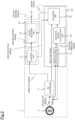
- Fig. 1 is a block diagram illustrating a monitoring control device 1 according to an embodiment of the present invention.
- the monitoring control device 1 illustrated in Fig. 1 is mounted to a vehicular drive system.
- the vehicular drive system is a system for driving a motor by electric power of a battery.
- a vehicle to which the drive system is mounted is a vehicle including a motor, such as a hybrid vehicle, a plug-in vehicle, and an electric vehicle.
- the motor is driven by a three-phase current supplied from an inverter (INV).
- the motor may function as an electric generator, and electric power generated by the motor in regeneration is supplied to the battery via the inverter.
- the RD converter 3 samples the analog signal output from the resolver 2, and generates a digital signal by an AD conversion (analog-digital conversion) of the sampled voltage value.
- the digital signal is a two-phase (AB phase) encoder signal obtained by sampling each of the sine wave and the cosine wave included in the analog signal.
- the AB phase digital signal includes information on a relative angle of the rotor.
- the RD converter 3 calculates an absolute angle of the rotor based on the detected value of the resolver 2.
- the absolute angle is a value indicating an absolute position of the rotor from a reference position with an angle.
- the relative angle indicates how much the rotor has moved before and after the moving, and corresponds to an amount of rotational displacement of the rotor.
- the absolute angle is indicated by a code
- the relative angle is indicated by an output waveform of the AB signal. That is, the RD converter 3 calculates the absolute angle and the relative angle of the rotor based on the analog signal from the resolver, and outputs an angle signal including the absolute angle and an angle signal including the relative angle.
- the RD converter 3 outputs the angle signal including the absolute angle to the first control device 10, and outputs the angle signal including the relative angle to the first control device 10 and the second control device 20.
- the absolute angle calculated by the RD converter 3 is referred to as a first absolute angle
- the relative angle calculated at the same timing as the first absolute angle is referred to as a first relative angle.
- the control unit 11 simultaneously obtains the first absolute angle and the first relative angle. Then, the control unit 11 computes a current angular velocity of the motor from the first absolute angle and/or the first relative angle. The control unit 11 calculates the control command value by a PI control based on a required torque input from outside, the computed angular velocity, and the like, and outputs the motor control signal to the inverter. The control unit 11 generates a first diagnostic signal based on the first absolute angle, and outputs it to the second control device 20. The first diagnostic signal includes information on the first absolute angle used for the motor control. That is, the control unit 11 outputs the information on the rotation angle of the rotor used for the motor control to the second control device 20 for the diagnosis.
- the signal blocking unit 12 blocks the motor control signal output from the first control device 10 to the inverter in response to a block signal transmitted from a diagnosis unit 23 described later.
- the block signal is output from the diagnosis unit 23 when a detection failure of the rotation state of the rotor is diagnosed to be present.
- the signal blocking unit 12 blocks the motor control signal generated by the control unit 11.
- the signal blocking unit 12 may determine that a failure is present in the detection of the rotation state of the rotor, and may perform fail-safe control of, for example stopping the motor control or issue an outside warning or the like.
- the signal blocking unit 12 outputs the motor control signal generated by the control unit 11 to the inverter without blocking it.
- the second control device 20 obtains the analog signal from the resolver, calculates the second absolute angle based on the analog signal, generates a second diagnostic signal based on the second absolute angle, and compares the first diagnostic signal with the second diagnostic signal to diagnose the presence/absence of the detection failure of the rotation state of the rotor.
- the second control device 20 includes a CPU and a memory such as a RAM or a ROM, and executes a program stored in the memory by the CPU, thereby executing various kinds of control functions.
- the second control device 20 includes the CPU different from the CPU included in the first control device 10.
- the second control device 20 includes an absolute angle calculation unit 21, an absolute angle estimation unit 22, and a diagnosis unit 23 as function blocks.
- the absolute angle calculation unit 21 specifies a sine function (sin ⁇ ) and a cosine function (cos ⁇ ) representing the rotation angle from the analog signal output from the resolver 2, and takes an arctangent (arctan [sin ⁇ /cos ⁇ ]), thereby calculating the absolute angle of the rotor.
- the calculation timing of the absolute angle in the absolute angle calculation unit 21 is a timing different from that of the first absolute angle calculated by the AD conversion in the RD converter 3. That is, the calculation timing of the absolute angle calculation unit 21 is not synchronized with the calculation timing of the RD converter 3, and they are different timings.
- an absolute angle calculated by the absolute angle calculation unit 21 is referred to as a second absolute angle.
- the absolute angle estimation unit 22 obtains the second relative angle calculated by the RD converter 3 at the same timing as the second absolute angle, and obtains the first relative angle from the control unit 11.
- the absolute angle estimation unit 22 estimates an estimation value of the first absolute angle based on the second absolute angle, the first relative angle, and the second relative angle using a formula (1) below.
- ⁇ 1 _ e ⁇ 2 ⁇ ⁇ 2 ⁇ ⁇ 1
- ⁇ 1_e indicates the estimation value of the first absolute angle
- ⁇ 2 indicates the second absolute angle
- ⁇ 1 indicates the first relative angle
- ⁇ 2 indicates the second relative angle.
- the absolute angle estimation unit 22 adds information on the estimation value of the first absolute angle to the second diagnostic signal generated by the absolute angle calculation unit 21, and outputs it as the second diagnostic signal to the diagnosis unit 23. Since the estimation value of the first absolute angle is a value calculated based on the second absolute angle, the second diagnostic signal output from the absolute angle estimation unit 22 to the diagnosis unit 23 is a signal based on the second absolute angle.
- the diagnosis unit 23 compares the first diagnostic signal output from the control unit 11 with the second diagnostic signal output from the absolute angle estimation unit 22, and diagnoses the presence/absence of the detection failure of the rotation state of the rotor. Specifically, the diagnosis unit 23 specifies the first absolute angle from the first diagnostic signal, specifies the estimation value of the first absolute angle from the second diagnostic signal, and calculates a difference between the first absolute angle and the estimation value of the first absolute angle. In the diagnosis unit 23, a determination threshold value for determining the detection failure is preliminarily set. The determination threshold value is set to be, for example, a value greater than a detection error.
- the diagnosis unit 23 determines that the absolute angle calculated by the RD converter 3 is an exact value, and diagnoses that the detection failure is not present. Meanwhile, when the difference between the first absolute angle and the estimation value of the first absolute angle is the determination threshold value or more, the diagnosis unit 23 determines that the detection failure is present. For example, when a failure occurs in the AD conversion by the RD converter 3, or when a failure occurs in a signal line of the main system or a signal line of the monitoring system, the value of the first absolute angle and/or the second absolute angle becomes an outlier.
- the first absolute angle is obtained from the first control device 10 using the signal line of the main system
- the second absolute angle is obtained using the signal line of the monitoring system with a time difference with the first absolute angle. Then, when the detection failure has occurred, a large angle difference is generated between the first absolute angle and the second absolute angle having the time difference.
- the detection failure is diagnosed based on a magnitude of the angle difference.
- the diagnosis unit 23 When the detection failure of the rotation state of the rotor is determined to be present, the diagnosis unit 23 outputs the block signal to the signal blocking unit 12. When the detection failure of the rotation state of the rotor is determined to be not present, the diagnosis unit 23 does not output the block signal to the signal blocking unit 12.
- the resolver 2 detects the rotation state of the rotor and outputs the analog signal in response to the detected rotation state
- the RD converter 3 calculates the first absolute angle of the rotor at the first timing based on the analog signal and outputs the signal including the information on the first absolute angle
- the first control device 10 generates the first diagnostic signal based on the first absolute angle and outputs the first diagnostic signal to the second control device 20.
- the second control device 20 calculates the second absolute angle of the rotor at a second timing different from the first timing based on the analog signal, generates the second diagnostic signal based on the second absolute angle, and compares the first diagnostic signal with the second diagnostic signal to diagnose the presence/absence of the detection failure of the rotation state of the rotor.
Landscapes
- Physics & Mathematics (AREA)
- General Physics & Mathematics (AREA)
- Engineering & Computer Science (AREA)
- Power Engineering (AREA)
- Signal Processing (AREA)
- Transmission And Conversion Of Sensor Element Output (AREA)
- Control Of Electric Motors In General (AREA)
- Testing And Monitoring For Control Systems (AREA)
Applications Claiming Priority (1)
| Application Number | Priority Date | Filing Date | Title |
|---|---|---|---|
| PCT/IB2020/000513 WO2021240191A1 (ja) | 2020-05-28 | 2020-05-28 | 監視制御装置及び監視制御方法 |
Publications (3)
| Publication Number | Publication Date |
|---|---|
| EP4160158A1 EP4160158A1 (en) | 2023-04-05 |
| EP4160158A4 EP4160158A4 (en) | 2023-07-26 |
| EP4160158B1 true EP4160158B1 (en) | 2024-07-10 |
Family
ID=78723022
Family Applications (1)
| Application Number | Title | Priority Date | Filing Date |
|---|---|---|---|
| EP20937193.9A Active EP4160158B1 (en) | 2020-05-28 | 2020-05-28 | Monitoring control device and monitoring control method |
Country Status (7)
| Country | Link |
|---|---|
| US (1) | US11781887B2 (https=) |
| EP (1) | EP4160158B1 (https=) |
| JP (1) | JP7395731B2 (https=) |
| CN (1) | CN115667852B (https=) |
| BR (1) | BR112022024150A2 (https=) |
| MX (1) | MX2022014712A (https=) |
| WO (1) | WO2021240191A1 (https=) |
Families Citing this family (3)
| Publication number | Priority date | Publication date | Assignee | Title |
|---|---|---|---|---|
| JP7632119B2 (ja) * | 2021-06-28 | 2025-02-19 | 日産自動車株式会社 | 監視制御装置及び監視制御方法 |
| JP7836493B2 (ja) * | 2022-05-19 | 2026-03-27 | 株式会社デンソー | 回転検出装置 |
| GB2623762B (en) * | 2022-10-24 | 2025-04-23 | Dalmatic Tnv As | A rotary encoder |
Family Cites Families (28)
| Publication number | Priority date | Publication date | Assignee | Title |
|---|---|---|---|---|
| JPS63243702A (ja) * | 1987-03-31 | 1988-10-11 | Kobe Steel Ltd | カウントチエツク式回転角検出装置 |
| JP3216491B2 (ja) * | 1995-09-08 | 2001-10-09 | トヨタ自動車株式会社 | レゾルバ異常検出装置及び方法 |
| JP3491526B2 (ja) * | 1998-05-27 | 2004-01-26 | トヨタ自動車株式会社 | Icチップの異常検出装置 |
| JP3460587B2 (ja) * | 1998-07-21 | 2003-10-27 | トヨタ自動車株式会社 | 回転角検出装置の異常を検出する異常検出装置 |
| JP3508643B2 (ja) * | 1999-09-16 | 2004-03-22 | トヨタ自動車株式会社 | レゾルバの信号処理装置および信号処理方法 |
| JP2003042754A (ja) | 2001-07-30 | 2003-02-13 | Alps Electric Co Ltd | 回転角検出装置 |
| JP2004061157A (ja) | 2002-07-25 | 2004-02-26 | Toyota Motor Corp | レゾルバの信号処理装置及び信号処理方法 |
| JP4521258B2 (ja) * | 2004-01-28 | 2010-08-11 | 日立オートモティブシステムズ株式会社 | レゾルバ/デジタル変換器及びこれを用いた制御システム |
| JP4589093B2 (ja) * | 2004-12-10 | 2010-12-01 | 日立オートモティブシステムズ株式会社 | 同期モータ駆動装置及び方法 |
| US7194377B1 (en) * | 2005-09-26 | 2007-03-20 | Hitachi Automotive Products (Usa), Inc. | Method for calibrating an analog sensor |
| JP4923730B2 (ja) * | 2006-05-24 | 2012-04-25 | トヨタ自動車株式会社 | レゾルバ角度検出における補償方法及びこれを用いた角度検出装置 |
| US7469193B2 (en) | 2006-11-16 | 2008-12-23 | Continental Automotive Systems Us, Inc. | Method and apparatus for resolver compensation |
| DE102008059775A1 (de) * | 2007-11-30 | 2009-06-04 | Continental Teves Ag & Co. Ohg | Absolut messende Lenkwinkelsensoranordnung |
| JP2009139096A (ja) | 2007-12-03 | 2009-06-25 | Toyota Motor Corp | 回転角検出装置 |
| JP5195738B2 (ja) * | 2009-12-24 | 2013-05-15 | トヨタ自動車株式会社 | 回転センサの異常判定装置 |
| JP5494969B2 (ja) * | 2010-11-04 | 2014-05-21 | 株式会社デンソー | 回転角検出システムの異常診断装置 |
| KR101683925B1 (ko) | 2011-12-08 | 2016-12-07 | 현대자동차주식회사 | 친환경 차량의 레졸버 비정상 출력 보상 방법 |
| CN204263601U (zh) * | 2014-11-13 | 2015-04-15 | 扬州大祺自动化技术有限公司 | 机械压力机角度显示器 |
| CN105774895A (zh) * | 2014-12-16 | 2016-07-20 | 上海航天汽车机电股份有限公司 | 一种方向盘绝对转角的计算方法和系统 |
| JP2016163454A (ja) * | 2015-03-03 | 2016-09-05 | トヨタ自動車株式会社 | モータ制御装置 |
| DE102015211258A1 (de) | 2015-06-18 | 2016-12-22 | Robert Bosch Gmbh | Vorrichtungen und Verfahren zur Auswertung eines Signals von einem Drehwinkelgeber |
| JP6555062B2 (ja) | 2015-10-01 | 2019-08-07 | 株式会社デンソー | 回転角検出装置 |
| CN108351225A (zh) | 2015-11-12 | 2018-07-31 | 大库输送机株式会社 | 检测装置的异常判定系统、检测装置、检测装置的异常判定装置、以及检测装置的异常判定方法 |
| JP2018128324A (ja) | 2017-02-07 | 2018-08-16 | 株式会社東海理化電機製作所 | 制御装置 |
| JP6862908B2 (ja) | 2017-02-27 | 2021-04-21 | 日産自動車株式会社 | 回転角度検出装置 |
| JP6338738B1 (ja) * | 2017-05-12 | 2018-06-06 | 三菱電機株式会社 | 回転角センサ情報の異常診断装置 |
| KR101950259B1 (ko) * | 2017-05-22 | 2019-02-22 | 주식회사 만도 | 전동식 조향장치의 조향정보 검출 장치 및 조향정보 검출방법 |
| KR102462592B1 (ko) * | 2017-08-16 | 2022-11-04 | 현대자동차주식회사 | 레졸버 위치오차 보상장치 및 방법 |
-
2020
- 2020-05-28 WO PCT/IB2020/000513 patent/WO2021240191A1/ja not_active Ceased
- 2020-05-28 US US17/927,450 patent/US11781887B2/en active Active
- 2020-05-28 JP JP2022526530A patent/JP7395731B2/ja active Active
- 2020-05-28 BR BR112022024150A patent/BR112022024150A2/pt unknown
- 2020-05-28 EP EP20937193.9A patent/EP4160158B1/en active Active
- 2020-05-28 CN CN202080101408.1A patent/CN115667852B/zh active Active
- 2020-05-28 MX MX2022014712A patent/MX2022014712A/es unknown
Also Published As
| Publication number | Publication date |
|---|---|
| MX2022014712A (es) | 2022-12-16 |
| US20230175871A1 (en) | 2023-06-08 |
| JPWO2021240191A1 (https=) | 2021-12-02 |
| CN115667852A (zh) | 2023-01-31 |
| WO2021240191A1 (ja) | 2021-12-02 |
| JP7395731B2 (ja) | 2023-12-11 |
| BR112022024150A2 (pt) | 2022-12-27 |
| US11781887B2 (en) | 2023-10-10 |
| EP4160158A4 (en) | 2023-07-26 |
| EP4160158A1 (en) | 2023-04-05 |
| CN115667852B (zh) | 2024-02-23 |
Similar Documents
| Publication | Publication Date | Title |
|---|---|---|
| US6281656B1 (en) | Synchronous motor control device electric motor vehicle control device and method of controlling synchronous motor | |
| JP3362537B2 (ja) | 電気自動車用駆動モータのフェールセーフ制御 | |
| EP4160158B1 (en) | Monitoring control device and monitoring control method | |
| EP3040690B1 (en) | Angle error correction device and angle error correction method for position detector | |
| JP3216491B2 (ja) | レゾルバ異常検出装置及び方法 | |
| US6694287B2 (en) | Phase angle diagnostics for sinusoidal controlled electric machine | |
| JP4256390B2 (ja) | 電気パワーステアリング・システムにおける故障検出 | |
| US6191550B1 (en) | Method and apparatus for detecting abnormality in rotation sensor | |
| US10270378B2 (en) | Arrangement and method for monitoring a PSM-machine | |
| KR101776474B1 (ko) | 레졸버 신호를 이용하는 모터 고장 진단 장치 및 방법 | |
| US11611303B2 (en) | Method of detecting connection fault of electric motor | |
| US20120242265A1 (en) | Method for operating an electric machine, and drive device | |
| US10060983B2 (en) | Method and apparatus for determining a physical quantity of a multiphase synchronous machine | |
| JPH11337373A (ja) | 回転センサ及びその異常診断方法及びそれを用いた電動機の制御システム | |
| JPWO2021240191A5 (https=) | ||
| JP2004147463A (ja) | モータ駆動装置 | |
| US11952018B2 (en) | Drive system for a vehicle, method for operating the drive system, and vehicle comprising drive system | |
| US20020091470A1 (en) | Control equipment and method for controlling an electric car | |
| JP5082481B2 (ja) | 回転角度位置算出装置及びモータ | |
| US10989572B2 (en) | Apparatus and method for checking the plausibility of an excitation signal for a rotary encoder | |
| JP7632119B2 (ja) | 監視制御装置及び監視制御方法 | |
| JP6451600B2 (ja) | 電圧センサ異常診断装置 | |
| CN114963952A (zh) | 霍尔传感器的故障诊断方法、装置及转向控制系统 | |
| JPH11248487A (ja) | レゾルバの異常検出装置 | |
| CN115638994A (zh) | 扭振故障确定方法、装置、系统和车辆 |
Legal Events
| Date | Code | Title | Description |
|---|---|---|---|
| STAA | Information on the status of an ep patent application or granted ep patent |
Free format text: STATUS: THE INTERNATIONAL PUBLICATION HAS BEEN MADE |
|
| PUAI | Public reference made under article 153(3) epc to a published international application that has entered the european phase |
Free format text: ORIGINAL CODE: 0009012 |
|
| STAA | Information on the status of an ep patent application or granted ep patent |
Free format text: STATUS: REQUEST FOR EXAMINATION WAS MADE |
|
| 17P | Request for examination filed |
Effective date: 20221117 |
|
| AK | Designated contracting states |
Kind code of ref document: A1 Designated state(s): AL AT BE BG CH CY CZ DE DK EE ES FI FR GB GR HR HU IE IS IT LI LT LU LV MC MK MT NL NO PL PT RO RS SE SI SK SM TR |
|
| REG | Reference to a national code |
Ref country code: DE Ref legal event code: R079 Free format text: PREVIOUS MAIN CLASS: G01D0005244000 Ipc: G01D0003080000 Ref country code: DE Ref legal event code: R079 Ref document number: 602020033939 Country of ref document: DE Free format text: PREVIOUS MAIN CLASS: G01D0005244000 Ipc: G01D0003080000 |
|
| A4 | Supplementary search report drawn up and despatched |
Effective date: 20230622 |
|
| RIC1 | Information provided on ipc code assigned before grant |
Ipc: G01D 5/20 20060101ALI20230616BHEP Ipc: G01D 3/08 20060101AFI20230616BHEP |
|
| DAV | Request for validation of the european patent (deleted) | ||
| DAX | Request for extension of the european patent (deleted) | ||
| GRAP | Despatch of communication of intention to grant a patent |
Free format text: ORIGINAL CODE: EPIDOSNIGR1 |
|
| STAA | Information on the status of an ep patent application or granted ep patent |
Free format text: STATUS: GRANT OF PATENT IS INTENDED |
|
| INTG | Intention to grant announced |
Effective date: 20240327 |
|
| GRAS | Grant fee paid |
Free format text: ORIGINAL CODE: EPIDOSNIGR3 |
|
| GRAA | (expected) grant |
Free format text: ORIGINAL CODE: 0009210 |
|
| STAA | Information on the status of an ep patent application or granted ep patent |
Free format text: STATUS: THE PATENT HAS BEEN GRANTED |
|
| AK | Designated contracting states |
Kind code of ref document: B1 Designated state(s): AL AT BE BG CH CY CZ DE DK EE ES FI FR GB GR HR HU IE IS IT LI LT LU LV MC MK MT NL NO PL PT RO RS SE SI SK SM TR |
|
| REG | Reference to a national code |
Ref country code: CH Ref legal event code: EP |
|
| REG | Reference to a national code |
Ref country code: DE Ref legal event code: R096 Ref document number: 602020033939 Country of ref document: DE |
|
| REG | Reference to a national code |
Ref country code: LT Ref legal event code: MG9D |
|
| REG | Reference to a national code |
Ref country code: NL Ref legal event code: MP Effective date: 20240710 |
|
| PG25 | Lapsed in a contracting state [announced via postgrant information from national office to epo] |
Ref country code: PT Free format text: LAPSE BECAUSE OF FAILURE TO SUBMIT A TRANSLATION OF THE DESCRIPTION OR TO PAY THE FEE WITHIN THE PRESCRIBED TIME-LIMIT Effective date: 20241111 |
|
| REG | Reference to a national code |
Ref country code: AT Ref legal event code: MK05 Ref document number: 1702392 Country of ref document: AT Kind code of ref document: T Effective date: 20240710 |
|
| PG25 | Lapsed in a contracting state [announced via postgrant information from national office to epo] |
Ref country code: NL Free format text: LAPSE BECAUSE OF FAILURE TO SUBMIT A TRANSLATION OF THE DESCRIPTION OR TO PAY THE FEE WITHIN THE PRESCRIBED TIME-LIMIT Effective date: 20240710 |
|
| PG25 | Lapsed in a contracting state [announced via postgrant information from national office to epo] |
Ref country code: PT Free format text: LAPSE BECAUSE OF FAILURE TO SUBMIT A TRANSLATION OF THE DESCRIPTION OR TO PAY THE FEE WITHIN THE PRESCRIBED TIME-LIMIT Effective date: 20241111 Ref country code: NL Free format text: LAPSE BECAUSE OF FAILURE TO SUBMIT A TRANSLATION OF THE DESCRIPTION OR TO PAY THE FEE WITHIN THE PRESCRIBED TIME-LIMIT Effective date: 20240710 |
|
| PG25 | Lapsed in a contracting state [announced via postgrant information from national office to epo] |
Ref country code: NO Free format text: LAPSE BECAUSE OF FAILURE TO SUBMIT A TRANSLATION OF THE DESCRIPTION OR TO PAY THE FEE WITHIN THE PRESCRIBED TIME-LIMIT Effective date: 20241010 |
|
| PG25 | Lapsed in a contracting state [announced via postgrant information from national office to epo] |
Ref country code: GR Free format text: LAPSE BECAUSE OF FAILURE TO SUBMIT A TRANSLATION OF THE DESCRIPTION OR TO PAY THE FEE WITHIN THE PRESCRIBED TIME-LIMIT Effective date: 20241011 Ref country code: FI Free format text: LAPSE BECAUSE OF FAILURE TO SUBMIT A TRANSLATION OF THE DESCRIPTION OR TO PAY THE FEE WITHIN THE PRESCRIBED TIME-LIMIT Effective date: 20240710 Ref country code: PL Free format text: LAPSE BECAUSE OF FAILURE TO SUBMIT A TRANSLATION OF THE DESCRIPTION OR TO PAY THE FEE WITHIN THE PRESCRIBED TIME-LIMIT Effective date: 20240710 |
|
| PG25 | Lapsed in a contracting state [announced via postgrant information from national office to epo] |
Ref country code: BG Free format text: LAPSE BECAUSE OF FAILURE TO SUBMIT A TRANSLATION OF THE DESCRIPTION OR TO PAY THE FEE WITHIN THE PRESCRIBED TIME-LIMIT Effective date: 20240710 |
|
| PG25 | Lapsed in a contracting state [announced via postgrant information from national office to epo] |
Ref country code: LV Free format text: LAPSE BECAUSE OF FAILURE TO SUBMIT A TRANSLATION OF THE DESCRIPTION OR TO PAY THE FEE WITHIN THE PRESCRIBED TIME-LIMIT Effective date: 20240710 |
|
| PG25 | Lapsed in a contracting state [announced via postgrant information from national office to epo] |
Ref country code: IS Free format text: LAPSE BECAUSE OF FAILURE TO SUBMIT A TRANSLATION OF THE DESCRIPTION OR TO PAY THE FEE WITHIN THE PRESCRIBED TIME-LIMIT Effective date: 20241110 Ref country code: AT Free format text: LAPSE BECAUSE OF FAILURE TO SUBMIT A TRANSLATION OF THE DESCRIPTION OR TO PAY THE FEE WITHIN THE PRESCRIBED TIME-LIMIT Effective date: 20240710 |
|
| PG25 | Lapsed in a contracting state [announced via postgrant information from national office to epo] |
Ref country code: HR Free format text: LAPSE BECAUSE OF FAILURE TO SUBMIT A TRANSLATION OF THE DESCRIPTION OR TO PAY THE FEE WITHIN THE PRESCRIBED TIME-LIMIT Effective date: 20240710 |
|
| PG25 | Lapsed in a contracting state [announced via postgrant information from national office to epo] |
Ref country code: ES Free format text: LAPSE BECAUSE OF FAILURE TO SUBMIT A TRANSLATION OF THE DESCRIPTION OR TO PAY THE FEE WITHIN THE PRESCRIBED TIME-LIMIT Effective date: 20240710 Ref country code: RS Free format text: LAPSE BECAUSE OF FAILURE TO SUBMIT A TRANSLATION OF THE DESCRIPTION OR TO PAY THE FEE WITHIN THE PRESCRIBED TIME-LIMIT Effective date: 20241010 |
|
| PG25 | Lapsed in a contracting state [announced via postgrant information from national office to epo] |
Ref country code: RS Free format text: LAPSE BECAUSE OF FAILURE TO SUBMIT A TRANSLATION OF THE DESCRIPTION OR TO PAY THE FEE WITHIN THE PRESCRIBED TIME-LIMIT Effective date: 20241010 Ref country code: PL Free format text: LAPSE BECAUSE OF FAILURE TO SUBMIT A TRANSLATION OF THE DESCRIPTION OR TO PAY THE FEE WITHIN THE PRESCRIBED TIME-LIMIT Effective date: 20240710 Ref country code: NO Free format text: LAPSE BECAUSE OF FAILURE TO SUBMIT A TRANSLATION OF THE DESCRIPTION OR TO PAY THE FEE WITHIN THE PRESCRIBED TIME-LIMIT Effective date: 20241010 Ref country code: LV Free format text: LAPSE BECAUSE OF FAILURE TO SUBMIT A TRANSLATION OF THE DESCRIPTION OR TO PAY THE FEE WITHIN THE PRESCRIBED TIME-LIMIT Effective date: 20240710 Ref country code: IS Free format text: LAPSE BECAUSE OF FAILURE TO SUBMIT A TRANSLATION OF THE DESCRIPTION OR TO PAY THE FEE WITHIN THE PRESCRIBED TIME-LIMIT Effective date: 20241110 Ref country code: HR Free format text: LAPSE BECAUSE OF FAILURE TO SUBMIT A TRANSLATION OF THE DESCRIPTION OR TO PAY THE FEE WITHIN THE PRESCRIBED TIME-LIMIT Effective date: 20240710 Ref country code: GR Free format text: LAPSE BECAUSE OF FAILURE TO SUBMIT A TRANSLATION OF THE DESCRIPTION OR TO PAY THE FEE WITHIN THE PRESCRIBED TIME-LIMIT Effective date: 20241011 Ref country code: FI Free format text: LAPSE BECAUSE OF FAILURE TO SUBMIT A TRANSLATION OF THE DESCRIPTION OR TO PAY THE FEE WITHIN THE PRESCRIBED TIME-LIMIT Effective date: 20240710 Ref country code: ES Free format text: LAPSE BECAUSE OF FAILURE TO SUBMIT A TRANSLATION OF THE DESCRIPTION OR TO PAY THE FEE WITHIN THE PRESCRIBED TIME-LIMIT Effective date: 20240710 Ref country code: BG Free format text: LAPSE BECAUSE OF FAILURE TO SUBMIT A TRANSLATION OF THE DESCRIPTION OR TO PAY THE FEE WITHIN THE PRESCRIBED TIME-LIMIT Effective date: 20240710 Ref country code: AT Free format text: LAPSE BECAUSE OF FAILURE TO SUBMIT A TRANSLATION OF THE DESCRIPTION OR TO PAY THE FEE WITHIN THE PRESCRIBED TIME-LIMIT Effective date: 20240710 |
|
| REG | Reference to a national code |
Ref country code: DE Ref legal event code: R097 Ref document number: 602020033939 Country of ref document: DE |
|
| PG25 | Lapsed in a contracting state [announced via postgrant information from national office to epo] |
Ref country code: SM Free format text: LAPSE BECAUSE OF FAILURE TO SUBMIT A TRANSLATION OF THE DESCRIPTION OR TO PAY THE FEE WITHIN THE PRESCRIBED TIME-LIMIT Effective date: 20240710 Ref country code: DK Free format text: LAPSE BECAUSE OF FAILURE TO SUBMIT A TRANSLATION OF THE DESCRIPTION OR TO PAY THE FEE WITHIN THE PRESCRIBED TIME-LIMIT Effective date: 20240710 Ref country code: RO Free format text: LAPSE BECAUSE OF FAILURE TO SUBMIT A TRANSLATION OF THE DESCRIPTION OR TO PAY THE FEE WITHIN THE PRESCRIBED TIME-LIMIT Effective date: 20240710 |
|
| PG25 | Lapsed in a contracting state [announced via postgrant information from national office to epo] |
Ref country code: EE Free format text: LAPSE BECAUSE OF FAILURE TO SUBMIT A TRANSLATION OF THE DESCRIPTION OR TO PAY THE FEE WITHIN THE PRESCRIBED TIME-LIMIT Effective date: 20240710 |
|
| PG25 | Lapsed in a contracting state [announced via postgrant information from national office to epo] |
Ref country code: CZ Free format text: LAPSE BECAUSE OF FAILURE TO SUBMIT A TRANSLATION OF THE DESCRIPTION OR TO PAY THE FEE WITHIN THE PRESCRIBED TIME-LIMIT Effective date: 20240710 |
|
| PG25 | Lapsed in a contracting state [announced via postgrant information from national office to epo] |
Ref country code: SK Free format text: LAPSE BECAUSE OF FAILURE TO SUBMIT A TRANSLATION OF THE DESCRIPTION OR TO PAY THE FEE WITHIN THE PRESCRIBED TIME-LIMIT Effective date: 20240710 Ref country code: IT Free format text: LAPSE BECAUSE OF FAILURE TO SUBMIT A TRANSLATION OF THE DESCRIPTION OR TO PAY THE FEE WITHIN THE PRESCRIBED TIME-LIMIT Effective date: 20240710 |
|
| PLBE | No opposition filed within time limit |
Free format text: ORIGINAL CODE: 0009261 |
|
| STAA | Information on the status of an ep patent application or granted ep patent |
Free format text: STATUS: NO OPPOSITION FILED WITHIN TIME LIMIT |
|
| 26N | No opposition filed |
Effective date: 20250411 |
|
| PGFP | Annual fee paid to national office [announced via postgrant information from national office to epo] |
Ref country code: DE Payment date: 20250423 Year of fee payment: 6 |
|
| PGFP | Annual fee paid to national office [announced via postgrant information from national office to epo] |
Ref country code: GB Payment date: 20250423 Year of fee payment: 6 |
|
| PGFP | Annual fee paid to national office [announced via postgrant information from national office to epo] |
Ref country code: FR Payment date: 20250423 Year of fee payment: 6 |
|
| PG25 | Lapsed in a contracting state [announced via postgrant information from national office to epo] |
Ref country code: SE Free format text: LAPSE BECAUSE OF FAILURE TO SUBMIT A TRANSLATION OF THE DESCRIPTION OR TO PAY THE FEE WITHIN THE PRESCRIBED TIME-LIMIT Effective date: 20240710 |
|
| REG | Reference to a national code |
Ref country code: CH Ref legal event code: H13 Free format text: ST27 STATUS EVENT CODE: U-0-0-H10-H13 (AS PROVIDED BY THE NATIONAL OFFICE) Effective date: 20251223 |
|
| PG25 | Lapsed in a contracting state [announced via postgrant information from national office to epo] |
Ref country code: LU Free format text: LAPSE BECAUSE OF NON-PAYMENT OF DUE FEES Effective date: 20250528 |
|
| PG25 | Lapsed in a contracting state [announced via postgrant information from national office to epo] |
Ref country code: CH Free format text: LAPSE BECAUSE OF NON-PAYMENT OF DUE FEES Effective date: 20250531 |
|
| REG | Reference to a national code |
Ref country code: BE Ref legal event code: MM Effective date: 20250531 |
|
| PG25 | Lapsed in a contracting state [announced via postgrant information from national office to epo] |
Ref country code: MC Free format text: LAPSE BECAUSE OF FAILURE TO SUBMIT A TRANSLATION OF THE DESCRIPTION OR TO PAY THE FEE WITHIN THE PRESCRIBED TIME-LIMIT Effective date: 20240710 |
|
| PG25 | Lapsed in a contracting state [announced via postgrant information from national office to epo] |
Ref country code: IE Free format text: LAPSE BECAUSE OF NON-PAYMENT OF DUE FEES Effective date: 20250528 |
|
| PG25 | Lapsed in a contracting state [announced via postgrant information from national office to epo] |
Ref country code: BE Free format text: LAPSE BECAUSE OF NON-PAYMENT OF DUE FEES Effective date: 20250531 |