EP4154717B1 - Vorrichtung zum verdrehen von teigstücken - Google Patents
Vorrichtung zum verdrehen von teigstücken Download PDFInfo
- Publication number
- EP4154717B1 EP4154717B1 EP22194755.9A EP22194755A EP4154717B1 EP 4154717 B1 EP4154717 B1 EP 4154717B1 EP 22194755 A EP22194755 A EP 22194755A EP 4154717 B1 EP4154717 B1 EP 4154717B1
- Authority
- EP
- European Patent Office
- Prior art keywords
- dough
- conveyor
- section
- piece
- holding belt
- Prior art date
- Legal status (The legal status is an assumption and is not a legal conclusion. Google has not performed a legal analysis and makes no representation as to the accuracy of the status listed.)
- Active
Links
Images


Classifications
-
- A—HUMAN NECESSITIES
- A21—BAKING; EDIBLE DOUGHS
- A21C—MACHINES OR EQUIPMENT FOR MAKING OR PROCESSING DOUGHS; HANDLING BAKED ARTICLES MADE FROM DOUGH
- A21C3/00—Machines or apparatus for shaping batches of dough before subdivision
- A21C3/08—Machines for twisting strips of dough, e.g. for making pretzels
-
- A—HUMAN NECESSITIES
- A21—BAKING; EDIBLE DOUGHS
- A21C—MACHINES OR EQUIPMENT FOR MAKING OR PROCESSING DOUGHS; HANDLING BAKED ARTICLES MADE FROM DOUGH
- A21C3/00—Machines or apparatus for shaping batches of dough before subdivision
- A21C3/02—Dough-sheeters; Rolling-machines; Rolling-pins
Definitions
- the invention relates to a device for twisting pieces of dough.
- the EP 2 253 215 A1 a device for twisting dough strips several times.
- dough strips are delivered on a conveyor belt, with two opposite ends protruding over the edges of the conveyor belt. The two ends are then grasped by two grippers. The dough strips are twisted by rotating the grippers. The grippers are also moved from the supplying conveyor belt to a discharge conveyor belt, onto which the twisted dough strips are placed.
- This system requires a high level of design and control technology, is difficult to clean and therefore causes high development, manufacturing and operating costs.
- a device for wrapping flat dough portions is known in which hooks are provided for initiating the wrapping process by folding a front edge of the dough portion upwards.
- a device is known which is configured for wrapping dough products, in this case filled ones.
- a retaining band is provided which is configured to engage with the filling product in order to ensure that the filling product is wrapped in the dough as desired.
- a dough twisting machine comprising a holding belt and several twisting belts, each of which is arranged parallel to a movable depositing surface.
- the holding belt moves the dough at the same speed as the depositing surface.
- At least one of the twisting belts moves faster than the depositing surface, so that the dough is twisted.
- a device for twisting dough pieces comprises a conveyor device configured to convey dough pieces in a production direction and at least one retaining belt arranged above the conveyor device and designed to engage with a first portion of one of the dough pieces arranged on the conveyor device.
- the device further comprises a rotating device which is designed to rotate a rotating portion of the dough piece relative to the first portion and upwards, while the retaining band engages with the first portion of the dough piece.
- An upward movement can be considered to be a movement directed away from the conveyor device.
- the rotating section and the first section can be rotated relative to each other.
- the construction of this device is significantly simpler than prior art designs with rotating grippers, which must also transport the twisted dough product from one conveyor belt to the other.
- the simultaneous engagement of the retaining band with the first section of the dough piece and the rotating device with the rotating section allows the sections to be twisted together, whereas prior art designs that have hooks only allow winding.
- the conveying device and the rotating device are arranged next to one another in a transverse direction that is oriented transversely, preferably perpendicularly, to the production direction. This can make it possible for the piece of dough to be rotated about an axis that runs transversely, preferably perpendicularly, to the production direction. This can be advantageous because the movement of the conveying device can be used to support the rotation of the rotating section.
- the rotating device comprises at least one hook which is arranged pivotably above the conveying device.
- a hook is configured to initially engage with the piece of dough, in particular with the rotating section. By pivoting the hook, the piece of dough, in particular the rotating section, can be rotated relative to the first section and upwards. By pivoting the hook further, the engagement with the piece of dough, in particular with the rotating section, can be automatically released.
- a hook arranged pivotably above the conveying device can therefore be a particularly simple example of a rotating device which can be operated without any control effort.
- the hook has an engagement section that is configured to engage with a piece of dough conveyed on the conveyor. This can mean that the engagement section can rest on the conveyor in a rest position and/or starting position of the hook or the distance of the engagement section to a surface of the conveyor can be smaller than a thickness of the piece of dough.
- the thickness of the piece of dough can be defined in a direction perpendicular to the surface of the conveyor.
- the hook is moved by the engagement of the engaging section with the dough piece and its conveyance by the conveying device from a starting position to a deflected position.
- This can have the advantage that no additional or separate drive has to be provided for the movement of the hook.
- the engagement section can be arranged in the deflected position of the hook upstream of a downstream end section of the retaining band.
- the downstream end section of the retaining band can be considered to be a section at which the piece of dough, in particular the first section of the piece of dough, is brought out of engagement with the retaining band.
- Such a configuration can have the advantage that the rotating section is rotated as far as possible, preferably by more than 90 degrees, particularly preferably by more than 180 degrees, relative to the first section, while the first section is still in engagement with the retaining band. This allows a more reliable rotation of the two sections relative to one another to be achieved.
- a pivot axis about which the hook can pivot is oriented transversely, preferably perpendicularly, to the production direction.
- the pivot axis can be arranged upstream of a downstream end section of the retaining belt.
- a conveying speed of the conveying device and a conveying speed of the retaining belt are different. This can assist the rotation of the first section and the rotating section relative to one another, in particular by rotating the first section in a suitable direction. It is particularly advantageous if a conveying speed of the conveying device is lower than a conveying speed of the retaining belt.
- a pressing device can be arranged downstream of the holding belt, in particular downstream of a downstream end section of the holding belt.
- the pressing device can in particular be arranged above the conveyor device.
- the pressing device can be configured to press twisted dough products, which were produced by twisting dough pieces as described above, onto the conveyor device. This can have the advantage that the twisted dough products do not return to an untwisted state of the dough piece, for example due to elastic restoring forces.
- the pressing device can be, for example, a conveyor belt or one or more conveyor belts, which can be arranged above the conveyor device.
- the application also relates to a method for twisting dough pieces.
- the method comprises conveying dough pieces in a production direction by a conveying device, engaging a first portion of one of the dough pieces arranged on the conveying device by at least one holding belt arranged above the conveying device, and rotating a rotating portion of the dough piece relative to the first portion and upwards, while the holding belt engages with the first section of the dough piece, by means of a rotating device.
- An upward movement can be considered a movement that is directed away from the conveyor device.
- the rotating section and the first section can be rotated relative to each other.
- the method enables a significantly simpler design of the executing device than prior art designs with rotating grippers, which additionally have to transport the twisted dough product from one conveyor belt to the other.
- the simultaneous engagement of the retaining band with the first section of the dough piece and the rotating device with the rotating section enables the sections to be rotated with each other, whereas prior art designs that have hooks only allow winding.
- first section and the rotating section are rotated by 180° relative to each other.
- the method can be particularly advantageous for such simple rotations, since in these applications, in addition to the simpler construction of the executing device compared to the state of the art, it can also ensure a comparably fast rotation.
- the first section and the turning section can be arranged next to each other in a transverse direction that is oriented transversely, preferably perpendicularly, to the production direction. This can make it possible for the piece of dough to be rotated about an axis that runs transversely, preferably perpendicularly, to the production direction. This can be advantageous because the movement of the conveyor device can be used to support the rotation of the turning section.
- the conveyor device and the retaining belt are driven at different conveying speeds. This can assist the rotation of the first section and the rotating section relative to one another, in particular by rotating the first section in a suitable direction. It is particularly advantageous if the conveyor device is driven at a conveying speed that is lower than a conveying speed of the retaining belt.
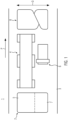
- a device 1 for twisting dough pieces 2 is shown in a schematic plan view from above.
- the device 1 can comprise a conveyor device 3.
- the conveyor device 3 can be configured to convey dough pieces in a production direction P.
- the conveyor device 3 can comprise a conveyor belt.
- the device 1 can further comprise a holding belt 4.
- the holding belt 4 can be arranged above the conveyor device 3.
- the holding belt 4 can be configured to engage with a first portion 5 of a dough piece 2 arranged on the conveyor device 3.
- the device 1 can further comprise a rotating device 6.
- the rotating device 6 can be configured to rotate a rotating portion 7 of the dough piece 2 relative to the first portion 5 and upwards, while the holding belt 4 engages with the first portion 5 of the dough piece 2.
- the first section 5 of the dough piece 2 and the turning section 7 of the dough piece 2 can be arranged next to each other in a transverse direction Q.
- the transverse direction Q can be oriented transversely, preferably perpendicularly, to the production direction P.
- the conveying device 3 and the turning device 6 can be arranged next to each other in the transverse direction Q.
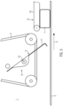
- the device 1 is shown in a schematic side view. It can be seen that the rotating device 6 can comprise at least one hook 9.
- the hook 9 can be arranged pivotably, in particular about a pivot axis 10, above the conveyor device 3.
- the pivot axis 10 can be oriented transversely, preferably perpendicularly, to the production direction P.
- the hook 9 can have an engagement section 11.
- the engagement section 11 can be configured to engage with a piece of dough 2 conveyed on the conveyor device 3.
- the engagement section 11 can be configured to engage with the rotating section 7 of the piece of dough 2 conveyed on the conveyor device 3.
- Figure 2 (and in the following Figures 3 to 5 ) of the dough piece 2 only the rotating section 7 is shown.
- the hook 9 can be moved from a starting position 12 (in Figure 2 shown) to a deflected position 13 (in Figure 4 shown) can be pivoted.
- the device 1 is also shown in a schematic side view, similar to the view from Figure 2 , shown.
- the hook 9 is, however, shown in a pivoting position between the starting position 12 and the deflected position 13. It can be seen that the movement of the conveyor device 3, the engagement of the engaging section 11 with the rotating section 7 and the pivoting movement of the hook 9 cause the rotating section 7 to be rotated upwards. Because at the same time the (in Figure 3 In order to hold the first section 5 (not shown) of the dough piece 2 by the holding band 4, the first section 5 and the rotating section 7 can be rotated relative to one another.
- the holding band 4 can have a downstream end section 14. At the downstream end section 14, the dough piece 2, in particular the first section 5 of the dough piece 2, can be brought out of engagement with the holding band 4.
- the pivot axis 10 can be arranged upstream of the downstream end section 14 of the holding band 4.
- the device 1 is shown in a schematic side view, which corresponds to the views in the Figures 2 and 3 resembles.
- the hook 9 is shown in the deflected position 13.
- the rotary section 7 is in a position opposite to the Figure 2 by approximately 180°. Through this rotation and the further conveyance of the dough piece 2 by the conveying device 3, the engagement between the engaging section 11 of the hook 9 and the rotating section 7 of the dough piece 2 can be released. It can be seen that the engaging section 11 of the hook 9 can be arranged in the deflected position 13 upstream of the downstream end section 14 of the retaining band 4.
- the device 1 can further comprise a pressing device 15.
- the pressing device 15 can be configured to press the dough piece 2 or the twisted dough product 8 onto the conveyor device 3. An initial engagement between the dough piece 2 and the pressing device 15 is already in Figure 4 recognizable.
- Figure 5 It can be seen that the turning section 7 of the dough piece 2 is rotated by 180° relative to the Figure 2 shown orientation of the turning section 7 of the dough piece 2.
- the pressing device 15 can comprise a conveyor belt 16. In Figure 1 For the sake of clarity, the pressing device 15 is not shown.
- the holding belt 4 and the conveyor device 3 can be driven at different conveying speeds.
- a particularly preferred embodiment is one in which the conveying speed of the conveyor device 3 is lower than the conveying speed of the holding belt 4. This allows the first section 5 of the dough piece 2 to be given a rotational impulse that is opposite to the direction of rotation of the rotating section 7 of the dough piece 2. This can assist the rotation of the rotating section 7 and the first section 5 relative to one another and/or prevent the first section 5 from rotating when the rotating section 7 rotates.
Landscapes
- Life Sciences & Earth Sciences (AREA)
- Engineering & Computer Science (AREA)
- Food Science & Technology (AREA)
- Manufacturing And Processing Devices For Dough (AREA)
Description
- Die Erfindung bezieht sich auf eine Vorrichtung zum Verdrehen von Teigstücken.
- Es sind verschiedene Arten von Teigprodukten bekannt, die bei ihrer Herstellung um eine Längsachse verdreht und/oder verdrillt werden. In Handarbeit werden solche Teigprodukte zu diesem Zweck an gegenüberliegenden Endabschnitten ergriffen und diese Endabschnitte manuell um eine zwischen den Endabschnitten orientierte Achse in entgegengesetzte Richtungen rotiert. Während diese Herstellungsweise für einfache Verdrehungen noch relativ einfach auch für Ungeübte zu bewerkstelligen ist, erfordern mehrfache Verdrehungen ein deutlich höheres Maß an Geschicklichkeit und Übung.
- Zu diesem Zweck offenbart die
EP 2 253 215 A1 eine Vorrichtung zum mehrfachen Verdrehen von Teigstreifen. Dazu werden Teigstreifen auf einem Förderband angeliefert, wobei zwei gegenüberliegende Enden über die Ränder des Förderbands hinausragen. Die beiden Enden werden dann von zwei Greifern ergriffen. Durch Rotieren der Greifer wird der Teigstreifen verdreht. Die Greifer werden außerdem von dem anliefernden Förderband zu einem abfördernden Förderband bewegt, auf das die verdrehten Teigstreifen abgelegt werden. Dieses System erfordert einen hohen konstruktiven und regelungstechnischen Aufwand, ist schwierig zu reinigen und verursacht daher hohe Entwicklungs- Herstellungs- und Betriebskosten. - Aus der
GB 183 848 A DE 10 2020 210 735.1 ist eine Vorrichtung bekannt, die zum Wickeln von, in diesem Fall gefüllten, Teigprodukten konfiguriert ist. Dort ist ein Halteband vorgesehen, das zum Eingreifen mit dem Füllgut konfiguriert ist, um sicherzustellen, dass das Füllgut wie gewünscht in den Teig eingewickelt wird. - In der
US 3 038 418 A wird eine Teigverdrehmaschine offenbart. Diese umfasst ein Halteband und mehrere Verdrehbänder die jeweils parallel zu einer beweglichen Ablageoberfläche angeordnet sind. Das Halteband bewegt den Teig gleichschnell wie die Ablageoberfläche. Mindestens eines der Verdrehbänder bewegt sich schneller als die Alblageoberfläche, sodass der Teig verdreht wird. - Es ist eine Aufgabe der Erfindung, eine verbesserte Vorrichtung zum Verdrehen, insbesondere zum einfachen Verdrehen, von Teigstücken anzugeben, die einfacher konstruiert und somit kostengünstiger zu entwickeln, herzustellen und zu betreiben ist.
- Diese Aufgabe wird gelöst durch eine Vorrichtung zum Verdrehen von Teigstücken mit den Merkmalen des Anspruchs 1.
- Es wird eine Vorrichtung zum Verdrehen von Teigstücken offenbart. Sie umfasst eine Fördervorrichtung, die zum Fördern von Teigstücken in einer Produktionsrichtung konfiguriert ist, und wenigstens ein Halteband, das oberhalb der Fördervorrichtung angeordnet ist und zum Eingreifen mit einem ersten Abschnitt eines der auf der Fördervorrichtung angeordneten Teigstücke konfiguriert ist. Die Vorrichtung umfasst des Weiteren eine Drehvorrichtung, die dazu eingerichtet ist, einen Drehabschnitt des Teigstücks relativ zu dem ersten Abschnitt und nach oben zu drehen, während das Halteband mit dem ersten Abschnitt des Teigstücks eingreift. Als eine Bewegung nach oben kann dabei eine Bewegung angesehen werden, die von der Fördervorrichtung fort gerichtet ist.
- Durch das Drehen des Drehabschnitts nach oben, während das Halteband im Eingriff mit dem ersten Abschnitt ist, können der Drehabschnitt und der erste Abschnitt relativ zueinander verdreht werden. Die Konstruktion dieser Vorrichtung ist deutlich einfacher als Ausführungen des Stands der Technik mit rotierenden Greifern, die zusätzlich noch das verdrehte Teigprodukt von einem Förderband zum anderen transportieren müssen. Außerdem ermöglicht der gleichzeitige Eingriff des Haltebands mit dem ersten Abschnitt des Teigstücks und der Drehvorrichtung mit dem Drehabschnitt ein Verdrehen der Abschnitte miteinander, wogegen Ausführungen aus dem Stand der Technik, die Haken aufweisen, nur ein Wickeln erlauben.
- Es ist denkbar, dass die Fördervorrichtung und die Drehvorrichtung in einer Querrichtung, die quer, vorzugsweise senkrecht, zu der Produktionsrichtung orientiert ist, nebeneinander angeordnet sind. Dadurch kann es ermöglicht werden, dass das Teigstück um eine Achse verdreht wird, die quer, vorzugsweise senkrecht, zu der Produktionsrichtung verläuft. Dies kann vorteilhaft sein, da die Bewegung der Fördervorrichtung dazu genutzt werden kann, das Drehen des Drehabschnitts zu unterstützen.
- Die Drehvorrichtung umfasst wenigstens einen Haken, der schwenkbar über der Fördervorrichtung angeordnet ist. Ein Haken ist dazu konfiguriert, zunächst mit dem Teigstück, insbesondere mit dem Drehabschnitt, einzugreifen. Durch Schwenken des Hakens kann das Teigstück, insbesondere der Drehabschnitt, relativ zu dem ersten Abschnitt und nach oben gedreht werden. Durch weiteres Schwenken des Hakens kann der Eingriff mit dem Teigstück, insbesondere mit dem Drehabschnitt, automatisch lösbar sein. Ein schwenkbar über der Fördervorrichtung angeordneter Haken kann also ein besonders einfaches Beispiel für eine Drehvorrichtung sein, die ohne steuerungsaufwand betreibbar sein kann.
- Der Haken weist einen Eingreifabschnitt auf, der zum Eingreifen mit einem auf der Fördervorrichtung geförderten Teigstück konfiguriert ist. Dies kann bedeuten, dass der Eingreifabschnitt in einer Ruheposition und/oder Ausgangsposition des Hakens auf der Fördervorrichtung aufliegen kann oder der Abstand des Eingreifabschnitts zu einer Oberfläche der Fördervorrichtung kleiner sein kann als eine Dicke des Teigstücks. Die Dicke des Teigstücks kann dabei in einer Richtung senkrecht zu der Oberfläche der Fördervorrichtung definiert sein.
- Es ist vorstellbar, dass der Haken durch den Eingriff des Eingreifabschnitts mit dem Teigstück und dessen Förderung durch die Fördervorrichtung von einer Ausgangsposition hin zu einer ausgelenkten Position schwenkbar ist. Dies kann den Vorteil aufweisen, dass kein zusätzlicher bzw. separater Antrieb für die Bewegung des Hakens vorgesehen werden muss. Vorzugsweise kann der Eingreifabschnitt in der ausgelenkten Position des Hakens stromaufwärts eines stromabwärtsseitigen Endabschnitts des Haltebands angeordnet sein. Als stromabwärtsseitiger Endabschnitt des Haltebands kann ein Abschnitt angesehen werden, an dem das Teigstück, insbesondere der erste Abschnitt des Teigstücks, außer Eingriff mit dem Halteband gebracht wird. Eine derartige Konfiguration kann den Vorteil aufweisen, dass der Drehabschnitt möglichst weit, vorzugsweise um mehr als 90 Grad, besonders bevorzugt um mehr als 180 Grad, relativ zu dem ersten Abschnitt gedreht wird, während der erste Abschnitt noch im Eingriff mit dem Halteband ist. Dadurch kann eine zuverlässigere Verdrehung der beiden Abschnitte relativ zueinander erreicht werden.
- Vorteilhafterweise ist eine Schwenkachse, um welche der Haken schwenkbar ist, quer, vorzugsweise senkrecht, zu der Produktionsrichtung orientiert. Auf diese Weise kann die weiter oben beschriebene Antriebswirkung der Fördervorrichtung besonders effektiv ausgenutzt werden. Die Schwenkachse kann stromaufwärts eines stromabwärtsseitigen Endabschnitts des Haltebands angeordnet sein.
- Es ist denkbar, dass eine Fördergeschwindigkeit der Fördervorrichtung und eine Fördergeschwindigkeit des Haltebandes unterschiedlich sind. Dadurch kann die Verdrehung des ersten Abschnitts und des Drehabschnitts relativ zueinander unterstützt werden, insbesondere indem der erste Abschnitt in eine geeignete Richtung gedreht wird. Besonders günstig ist es, wenn eine Fördergeschwindigkeit der Fördervorrichtung geringer ist als eine Fördergeschwindigkeit des Haltebandes.
- Stromabwärts des Haltebandes, insbesondere stromabwärts eines stromabwärtsseitigen Endabschnitts des Haltebands, kann eine Andrückvorrichtung angeordnet sein. Die Andrückvorrichtung kann insbesondere oberhalb der Fördervorrichtung angeordnet sein. Zusätzlich oder alternativ kann die Andrückvorrichtung dazu konfiguriert sein, verdrehte Teigprodukte, die wie oben beschrieben durch verdrehen von Teigstücken erzeugt wurden, an die Fördervorrichtung anzudrücken. Dies kann den Vorteil aufweisen, dass die verdrehten Teigprodukte nicht, bspw. durch elastische Rückstellkräfte, nicht wieder in einen unverdrehten Zustand des Teigstücks zurücckehren. Bei der Andrückvorrichtung kann es sich z. B. um ein Förderband oder einen oder mehrere Förderriemen handeln, das bzw. die oberhalb der Fördervorrichtung angeordnet sein kann bzw. können.
- Die Anmeldung bezieht sich auch auf ein Verfahren zum Verdrehen von Teigstücken. Das Verfahren umfasst Fördern von Teigstücken in einer Produktionsrichtung durch eine Fördervorrichtung, Eingreifen mit einem ersten Abschnitt eines der auf der Fördervorrichtung angeordneten Teigstücke durch wenigstens ein Halteband, das oberhalb der Fördervorrichtung angeordnet ist, und Drehen eines Drehabschnitts des Teigstücks relativ zu dem ersten Abschnitt und nach oben, während das Halteband mit dem ersten Abschnitt des Teigstücks eingreift, durch eine Drehvorrichtung. Als eine Bewegung nach oben kann dabei eine Bewegung angesehen werden, die von der Fördervorrichtung fort gerichtet ist.
- Durch das Drehen des Drehabschnitts nach oben, während das Halteband im Eingriff mit dem ersten Abschnitt ist, können der Drehabschnitt und der erste Abschnitt relativ zueinander verdreht werden. Das Verfahren ermöglicht eine deutlich einfachere Konstruktion der ausführenden Vorrichtung als Ausführungen des Stands der Technik mit rotierenden Greifern, die zusätzlich noch das verdrehte Teigprodukt von einem Förderband zum anderen transportieren müssen. Außerdem ermöglicht der gleichzeitige Eingriff des Haltebands mit dem ersten Abschnitt des Teigstücks und der Drehvorrichtung mit dem Drehabschnitt ein Verdrehen der Abschnitte miteinander, wogegen Ausführungen aus dem Stand der Technik, die Haken aufweisen, nur ein Wickeln erlauben.
- Es ist denkbar, dass der erste Abschnitt und der Drehabschnitt relativ zueinander um 180° verdreht werden. Für solche einfachen Verdrehungen kann das Verfahren besonders vorteilhaft sein, da es bei diesen Anwendungsfällen, zusätzlich zu der gegenüber dem Stand der Technik einfacheren Konstruktion der ausführenden Vorrichtung, auch noch eine vergleichbar schnelle Verdrehung gewährleisten kann.
- Der erste Abschnitt und der Drehabschnitt können in einer Querrichtung, die quer, vorzugsweise senkrecht, zu der Produktionsrichtung orientiert ist, nebeneinander angeordnet sein. Dadurch kann es ermöglicht werden, dass das Teigstück um eine Achse verdreht wird, die quer, vorzugsweise senkrecht, zu der Produktionsrichtung verläuft. Dies kann vorteilhaft sein, da die Bewegung der Fördervorrichtung dazu genutzt werden kann, das Drehen des Drehabschnitts zu unterstützen.
- Es kann vorteilhaft sein, wenn die Fördervorrichtung und das Halteband mit unterschiedlichen Fördergeschwindigkeiten angetrieben werden. Dadurch kann die Verdrehung des ersten Abschnitts und des Drehabschnitts relativ zueinander unterstützt werden, insbesondere indem der erste Abschnitt in eine geeignete Richtung gedreht wird. Besonders günstig ist es, wenn die Fördervorrichtung mit einer Fördergeschwindigkeit angetrieben wird, die geringer ist als eine Fördergeschwindigkeit des Haltebands.
- Die Erfindung bezieht sich auf eine Vorrichtung sowie auf ein Verfahren der vorstehend beschriebenen Art. Im Folgenden wird eine vorteilhafte Ausführung anhand von Zeichnungen beispielhaft erläutert.
-
Figur 1 zeigt eine schematische Draufsicht einer Vorrichtung zum Verdrehen von Teigstücken. -
Figuren 2 bis 5 zeigen schematische Seitenansichten der Vorrichtung ausFigur 1 , wobei ein Haken in unterschiedlichen Schwenkpositionen dargestellt ist. - In
Figur 1 ist eine Vorrichtung 1 zum Verdrehen von Teigstücken 2 in einer schematischen Draufsicht von oben dargestellt. Die Vorrichtung 1 kann eine Fördervorrichtung 3 umfassen. Die Fördervorrichtung 3 kann zum Fördern von Teigstücken in einer Produktionsrichtung P konfiguriert sein. Wie im vorliegenden Ausführungsbeispiel, kann die die Fördervorrichtung 3 ein Förderband umfassen. Die Vorrichtung 1 kann des Weiteren ein Halteband 4 umfassen. Das Halteband 4 kann oberhalb der Fördervorrichtung 3 angeordnet sein. Wie im vorliegenden Ausführungsbeispiel, kann das Halteband 4 zum Eingreifen mit einem ersten Abschnitt 5 eines auf der Fördervorrichtung 3 angeordneten Teigstücks 2 konfiguriert sein. Die Vorrichtung 1 kann des Weiteren eine Drehvorrichtung 6 umfassen. Die Drehvorrichtung 6 kann dazu eingerichtet sein, einen Drehabschnitt 7 des Teigstücks 2 relativ zu dem ersten Abschnitt 5 und nach oben zu drehen, während das Halteband 4 mit dem ersten Abschnitt 5 des Teigstücks 2 eingreift. - Der erste Abschnitt 5 des Teigstücks 2 und der Drehabschnitt 7 des Teigstücks 2 können in einer Querrichtung Q nebeneinander angeordnet sein. Die Querrichtung Q kann quer, vorzugsweise senkrecht, zu der Produktionsrichtung P orientiert sein. Die Fördervorrichtung 3 und die Drehvorrichtung 6 können in der Querrichtung Q nebeneinander angeordnet sein. Durch Verdrehen des Drehabschnitts 7 des Teigstücks 2 relativ zu dem ersten Abschnitt 5 des Teigstücks 2 kann ein verdrehtes Teigprodukt 8 erzeugt werden.
- In
Figur 2 ist die Vorrichtung 1 in einer schematischen Seitenansicht dargestellt. So ist zu erkennen, dass die Drehvorrichtung 6 wenigstens einen Haken 9 umfassen kann. Der Haken 9 kann schwenkbar, insbesondere um eine Schwenkachse 10, über der Fördervorrichtung 3 angeordnet sein. Die Schwenkachse 10 kann quer, vorzugsweise senkrecht, zu der Produktionsrichtung P orientiert sein. Der Haken 9 kann einen Eingreifabschnitt 11 aufweisen. Der Eingreifabschnitt 11 kann zum Eingreifen mit einem auf der Fördervorrichtung 3 geförderten Teigstück 2 konfiguriert sein. Insbesondere kann der Eingreifabschnitt 11 zum Eingreifen mit dem Drehabschnitt 7 des auf der Fördervorrichtung 3 geförderten Teigstücks 2 konfiguriert sein. - Zur besseren Übersichtlichkeit ist in
Figur 2 (sowie in den folgendenFiguren 3 bis 5 ) von dem Teigstück 2 lediglich der Drehabschnitt 7 dargestellt. Durch den Eingriff des Eingreifabschnitts 11 mit dem Teigstück 2, insbesondere dem Drehabschnitt 7 des Teigstücks 2, und der Förderung des Teigstücks 2 durch die Fördervorrichtung 3 kann der Haken 9 von einer Ausgangsposition 12 (inFigur 2 dargestellt) hin zu einer ausgelenkten Position 13 (inFigur 4 dargestellt) schwenkbar sein. - In
Figur 3 ist die Vorrichtung 1 ebenfalls in einer schematischen Seitenansicht, ähnlich der Ansicht ausFigur 2 , dargestellt. Der Haken 9 ist jedoch in einer Schwenkposition zwischen der Ausgangsposition 12 und der ausgelenkten Position 13 dargestellt. Es ist erkennbar, dass durch die Bewegung der Fördervorrichtung 3, den Eingriff des Eingreifabschnitts 11 mit dem Drehabschnitt 7 sowie die Schwenkbewegung des Hakens 9 der Drehabschnitt 7 nach oben gedreht werden kann. Dadurch, dass gleichzeitig der (inFigur 3 nicht gezeigte) erste Abschnitt 5 des Teigstücks 2 durch das Halteband 4 gehalten werden kann, können der erste Abschnitt 5 und der Drehabschnitt 7 relativ zueinander verdreht werden. Das Halteband 4 kann einen stromabwärtsseitigen Endabschnitt 14 aufweisen. An dem stromabwärtsseitigen Endabschnitt 14 kann das Teigstück 2, insbesondere der erste Abschnitt 5 des Teigstücks 2, außer Eingriff mit dem Halteband 4 gebracht werden. Die Schwenkachse 10 kann stromaufwärts des stromabwärtsseitigen Endabschnitts 14 des Haltebands 4 angeordnet sein. - In
Figur 4 ist die Vorrichtung 1 in einer schematischen Seitenansicht dargestellt, die den Ansichten aus denFiguren 2 und3 ähnelt. InFigur 4 ist der Haken 9 in der ausgelenkten Position 13 dargestellt. Der Drehabschnitt 7 ist in einer gegenüber der inFigur 2 um annähernd 180° gedrehten Orientierung dargestellt. Durch diese Drehung sowie die Weiterförderung des Teigstücks 2 durch die Fördervorrichtung 3 kann der Eingriff zwischen dem Eingreifabschnitt 11 des Hakens 9 und dem Drehabschnitt 7 des Teigstücks 2 lösbar sein. Es ist zu erkennen, dass der Eingreifabschnitt 11 des Hakens 9 in der ausgelenkten Position 13 stromaufwärts des stromabwärtsseitigen Endabschnitts 14 des Haltebands 4 angeordnet sein kann. - Die Vorrichtung 1 kann des Weiteren eine Andrückvorrichtung 15 umfassen. Die Andrückvorrichtung 15 kann dazu konfiguriert sein, das Teigstück 2 bzw. das verdrehte Teigprodukt 8 an die Fördervorrichtung 3 anzudrücken. Ein beginnender Eingriff zwischen dem Teigstück 2 und der Andrückvorrichtung 15 ist bereits in
Figur 4 erkennbar. InFigur 5 ist zu sehen, dass der Drehabschnitt 7 des Teigstücks 2 um 180° gegenüber der inFigur 2 gezeigten Orientierung des Drehabschnitts 7 des Teigstücks 2gedreht wurde. Die Andrückvorrichtung 15 kann ein Förderband 16 umfassen. InFigur 1 ist die Andrückvorrichtung 15 der besseren Übersichtlichkeit halber nicht dargestellt. - In der bevorzugten Ausführung der Vorrichtung 1 können das Halteband 4 und die Fördervorrichtung 3 mit unterschiedlichen Fördergeschwindigkeiten angetrieben werden. Besonders bevorzugt ist dabei eine Ausführung, in der die Fördergeschwindigkeit der Fördervorrichtung 3 geringer ist als die Fördergeschwindigkeit des Haltebands 4. Dadurch kann dem ersten Abschnitt 5 des Teigstücks 2 ein Drehimpuls aufgeprägt werden, der der Drehrichtung des Drehabschnitts 7 des Teigstücks 2 entgegengesetzt ist. Dadurch kann das Verdrehen des Drehabschnitts 7 und des ersten Abschnitts 5 relativ zueinander unterstützt werden und/oder verhindert werden, dass der erste Abschnitt 5 beim Drehen des Drehabschnitts 7 mitgedreht wird.
Claims (12)
- Vorrichtung (1) zum Verdrehen von Teigstücken (2), umfassend:eine Fördervorrichtung (3), die zum Fördern von Teigstücken (2) in einer Produktionsrichtung (P) konfiguriert ist,wenigstens ein Halteband (4), das oberhalb der Fördervorrichtung (3) angeordnet ist und zum Eingreifen mit einem ersten Abschnitt (5) eines der auf der Fördervorrichtung (3) angeordneten Teigstücke (2) konfiguriert ist, undeine Drehvorrichtung (6), die dazu eingerichtet ist, einen Drehabschnitt (7) des Teigstücks (2) relativ zu dem ersten Abschnitt (5) und nach oben zu drehen, während das Halteband (4) mit dem ersten Abschnitt (5) des Teigstücks (2) eingreift, dadurch gekennzeichnet, dass die Drehvorrichtung (6) wenigstens einen Haken (9) umfasst, der schwenkbar über der Fördervorrichtung (3) angeordnet ist, wobei der Haken (9) einen Eingreifabschnitt (11) aufweist, der zum Eingreifen mit einem auf der Fördervorrichtung (3) geförderten Teigstück (2) konfiguriert ist.
- Vorrichtung nach Anspruch 1, wobei die Fördervorrichtung (3) und die Drehvorrichtung (6) in einer Querrichtung (Q), die quer, vorzugsweise senkrecht, zu der Produktionsrichtung (P) orientiert ist, nebeneinander angeordnet sind.
- Vorrichtung nach einem der vorangehenden Ansprüche, wobei der Haken (9) durch den Eingriff des Eingreifabschnitts (11) mit dem Teigstück (2) und dessen Förderung durch die Fördervorrichtung (3) von einer Ausgangsposition (12) hin zu einer ausgelenkten Position (13) schwenkbar ist, wobei vorzugsweise der Eingreifabschnitt (11) in der ausgelenkten Position (13) des Hakens (9) stromaufwärts eines stromabwärtsseitigen Endabschnitts (14) des Haltebands (4) angeordnet ist.
- Vorrichtung nach einem der vorangehenden Ansprüche, wobei eine Schwenkachse (10), um welche der Haken (9) schwenkbar ist, quer, vorzugsweise senkrecht, zu der Produktionsrichtung (P) orientiert ist.
- Vorrichtung nach Anspruch 4, wobei die Schwenkachse (10) stromaufwärts eines stromabwärtsseitigen Endabschnitts (14) des Haltebands (4) angeordnet ist.
- Vorrichtung nach einem der vorangehenden Ansprüche, wobei eine Fördergeschwindigkeit der Fördervorrichtung (3) und eine Fördergeschwindigkeit des Haltebandes (4) unterschiedlich sind.
- Vorrichtung nach einem der vorangehenden Ansprüche, wobei eine Fördergeschwindigkeit der Fördervorrichtung (3) geringer ist als eine Fördergeschwindigkeit des Haltebandes (4).
- Verfahren zum Verdrehen von Teigstücken (2) durch eine Vorrichtung nach einem der vorangehenden Ansprüche, das Verfahren umfassend:Fördern von Teigstücken (2) in einer Produktionsrichtung (P) durch die Fördervorrichtung (3),Eingreifen mit einem ersten Abschnitt (5) eines der auf der Fördervorrichtung (3) angeordneten Teigstücke (2) durch das Halteband (4), das oberhalb der Fördervorrichtung (3) angeordnet istDrehen eines Drehabschnitts (6) des Teigstücks (2) relativ zu dem ersten Abschnitt (5) und nach oben, während das Halteband (4) mit dem ersten Abschnitt (5) des Teigstücks (2) eingreift, durch die Drehvorrichtung (6).
- Verfahren nach Anspruch 8, wobei der erste Abschnitt (5) und der Drehabschnitt (7) relativ zueinander um 180° verdreht werden.
- Verfahren nach Anspruch 8 oder 9, wobei der erste Abschnitt (5) und der Drehabschnitt (7) in einer Querrichtung (Q), die quer, vorzugsweise senkrecht, zu der Produktionsrichtung (P) orientiert ist, nebeneinander angeordnet sind.
- Verfahren nach einem der Ansprüche 8-10, wobei die Fördervorrichtung (3) und das Halteband (4) mit unterschiedlichen Fördergeschwindigkeiten angetrieben werden.
- Verfahren nach einem der Ansprüche 8-11, wobei die Fördervorrichtung (3) mit einer Fördergeschwindigkeit angetrieben wird, die geringer ist als eine Fördergeschwindigkeit des Haltebands (4).
Applications Claiming Priority (1)
| Application Number | Priority Date | Filing Date | Title |
|---|---|---|---|
| DE102021124622.9A DE102021124622A1 (de) | 2021-09-23 | 2021-09-23 | Vorrichtung zum Verdrehen von Teigstücken |
Publications (3)
| Publication Number | Publication Date |
|---|---|
| EP4154717A1 EP4154717A1 (de) | 2023-03-29 |
| EP4154717C0 EP4154717C0 (de) | 2024-07-24 |
| EP4154717B1 true EP4154717B1 (de) | 2024-07-24 |
Family
ID=83270718
Family Applications (1)
| Application Number | Title | Priority Date | Filing Date |
|---|---|---|---|
| EP22194755.9A Active EP4154717B1 (de) | 2021-09-23 | 2022-09-09 | Vorrichtung zum verdrehen von teigstücken |
Country Status (4)
| Country | Link |
|---|---|
| US (1) | US12471601B2 (de) |
| EP (1) | EP4154717B1 (de) |
| CN (1) | CN218959924U (de) |
| DE (2) | DE102021124622A1 (de) |
Families Citing this family (1)
| Publication number | Priority date | Publication date | Assignee | Title |
|---|---|---|---|---|
| US12285020B1 (en) * | 2024-11-25 | 2025-04-29 | Gary Gottenbusch | Braided soft pretzel apparatus and method |
Family Cites Families (41)
| Publication number | Priority date | Publication date | Assignee | Title |
|---|---|---|---|---|
| GB183848A (en) | 1922-07-28 | 1923-07-26 | Isidore De Haan | Improvements relating to dough moulding machinery |
| US1906847A (en) | 1932-10-10 | 1933-05-02 | Fitzgerald Thomas | Dough twisting or braiding machine |
| US2132158A (en) * | 1938-06-01 | 1938-10-04 | Carl C Guldbech | Dough twisting machine |
| US3028821A (en) * | 1959-09-18 | 1962-04-10 | Chester E Borck | Dough twister |
| US3038418A (en) | 1960-02-15 | 1962-06-12 | Victor F Gugler | Dough twisting machine |
| US3993422A (en) * | 1972-03-10 | 1976-11-23 | Lu, Brun & Associes S.A. | Machine for the manufacture of twisted dough articles |
| US3861291A (en) * | 1973-01-05 | 1975-01-21 | Itt | Rolling apparatus |
| GB1450576A (en) | 1973-08-09 | 1976-09-22 | Winner Food Products Ltd | Manufacture of filled pastry rolls |
| US4008025A (en) * | 1974-11-15 | 1977-02-15 | Pak-It Mgf Co., Inc. | Bread dough rounder bar |
| US4147809A (en) * | 1977-02-22 | 1979-04-03 | Thompson Bagel Machine Mfg. Corporation | Method and apparatus for sizing and forming dough bodies |
| US4608919A (en) | 1984-11-01 | 1986-09-02 | Prows Reed N | Burrito machine |
| US4767638A (en) * | 1987-07-28 | 1988-08-30 | Entenmann's, Inc. | Apparatus and method for twisting pastry dough and the like |
| DE3903122C1 (en) | 1989-02-02 | 1990-05-17 | A. Fritsch Gmbh & Co Kg, 8711 Markt-Einersheim, De | Method and device for twisting strips of dough |
| NL9202023A (nl) * | 1992-11-20 | 1994-06-16 | Kaak J H Holding | Inrichting en werkwijze voor het vormen van een deegstreng. |
| JP2750813B2 (ja) * | 1994-03-23 | 1998-05-13 | レオン自動機株式会社 | クロワッサン生地の巻き上げ装置 |
| NL1000637C2 (nl) * | 1995-06-22 | 1996-12-24 | Kaak Johan H B | Inrichting en werkwijze voor het vormen van een deegstreng. |
| US5786016A (en) * | 1997-05-09 | 1998-07-28 | Campbell Technologies, Inc. | Process and device for shaping baker's dough pieces |
| US5976599A (en) * | 1998-03-17 | 1999-11-02 | Campagna Turano Bakeries, Inc. | Apparatus and method for making dough roll |
| JP3242620B2 (ja) * | 1998-06-05 | 2001-12-25 | レオン自動機株式会社 | 棒状パン生地の搬送方法及び搬送装置 |
| US20030118714A1 (en) * | 2001-12-21 | 2003-06-26 | Michael Foods Of Delaware, Inc. | Formulation and process to prepare a premium formulated fried egg |
| NL1024916C2 (nl) | 2003-12-01 | 2005-06-02 | Tech Buro Kortlever B V | Inrichting en werkwijze voor het vervaardigen van samengestelde voedingsproducten. |
| EP1726209B1 (de) | 2005-05-23 | 2013-11-13 | Fritsch GmbH | Wickelsystem für Teigstücke und Füllgut |
| DE202006005231U1 (de) | 2006-03-31 | 2006-06-08 | René Senn AG | Vorrichtung zum Aufrollen von flächigen Lebensmittelprodukten |
| DE202008000083U1 (de) | 2008-07-03 | 2009-08-20 | Bendix, Conrad | Vorrichtung zur Herstellung von gerollten Speisen mit oder ohne Füllung |
| ES2616287T3 (es) | 2009-05-19 | 2017-06-12 | Radie B.V. | Dispositivo para retorcer tiras de masa alargadas |
| AT508444B1 (de) * | 2009-07-07 | 2013-03-15 | Koenig Maschinen Gmbh | Vorrichtung zur teigbandführung |
| JP5534782B2 (ja) * | 2009-11-09 | 2014-07-02 | 敷島製パン株式会社 | 食用生地整形装置 |
| EP2366290B1 (de) | 2010-03-18 | 2014-03-26 | Fritsch GmbH | Teigwickelvorrichtung, ausgebildet zur maschinellen Herstellung eines gewickelten Teigprodukts aus einem Ausgangsteigstück, sowie zugehöriges Verfahren |
| US8505445B2 (en) | 2010-12-20 | 2013-08-13 | Ou-Young Robert | Device for forming stuffed food with a pastry case by multiple folding |
| GB2487944B (en) * | 2011-02-09 | 2018-02-21 | Spice Application Systems Ltd | A comestible product coating delivery method and apparatus |
| EP2529629B8 (de) * | 2011-06-01 | 2016-12-07 | Radie B.V. | Verfahren und Vorrichtung zur Herstellung von einem mit Trennblatt aufgerollten Teigstück |
| CN104470475B (zh) * | 2012-05-24 | 2017-04-19 | 武田有限公司 | 用于提供卷绕的胶原蛋白载体的设备和工艺 |
| JP6499619B2 (ja) | 2016-08-05 | 2019-04-10 | レオン自動機株式会社 | 食製品の製造方法及び食製品製造装置 |
| EP3323293B1 (de) * | 2016-11-17 | 2019-08-21 | Radie B.V. | Teigstrasse zur verarbeitung von klebrigen teigarten |
| JP7198745B2 (ja) | 2017-10-20 | 2023-01-04 | 株式会社ニチレイフーズ | 巻き食品の製造装置及び製造方法 |
| JP6457676B1 (ja) | 2018-03-14 | 2019-01-23 | 株式会社マスダック | あん巻き機及びあん巻きの製造方法 |
| JP7090700B2 (ja) * | 2018-05-31 | 2022-06-24 | レオン自動機株式会社 | 食品生地片の巻き成形装置及びその方法 |
| DE102020210735A1 (de) | 2020-08-25 | 2022-03-03 | Fritsch Bakery Technologies GmbH & Co. KG | Vorrichtung zum erzeugen von gefüllten teigprodukten |
| US11896015B1 (en) * | 2023-02-24 | 2024-02-13 | MingsBings Inc. | Wrapping apparatus for making handheld food |
| NL2034479B1 (en) * | 2023-03-30 | 2024-10-04 | Radie Bv | Device for providing a dough sheet provided with a layer of fat |
| EP4529769B1 (de) * | 2023-09-28 | 2026-04-15 | Radie B.V. | Vorrichtung zum verdrehen von teigstücken |
-
2021
- 2021-09-23 DE DE102021124622.9A patent/DE102021124622A1/de not_active Withdrawn
-
2022
- 2022-09-09 DE DE202022002947.0U patent/DE202022002947U1/de active Active
- 2022-09-09 EP EP22194755.9A patent/EP4154717B1/de active Active
- 2022-09-22 CN CN202222516829.XU patent/CN218959924U/zh active Active
- 2022-09-23 US US17/951,927 patent/US12471601B2/en active Active
Also Published As
| Publication number | Publication date |
|---|---|
| EP4154717A1 (de) | 2023-03-29 |
| DE102021124622A1 (de) | 2023-03-23 |
| DE202022002947U1 (de) | 2024-02-07 |
| CN218959924U (zh) | 2023-05-05 |
| US12471601B2 (en) | 2025-11-18 |
| US20230093732A1 (en) | 2023-03-23 |
| EP4154717C0 (de) | 2024-07-24 |
Similar Documents
| Publication | Publication Date | Title |
|---|---|---|
| DE69713440T2 (de) | Vorrichtung zum Umhüllen eines Gegenstandes mit einer Folie | |
| EP1844659B1 (de) | Direktanbindung von Wurstclip- und Wurstfördereinrichtung | |
| DE3215008A1 (de) | Foerdervorrichtung fuer suesswaren u.dgl. gegenstaende | |
| EP3959983A1 (de) | Vorrichtung zum erzeugen von gefüllten teigprodukten | |
| DD239517A5 (de) | Vorrichtung und verfahren zur kontinuierlichen herstellung von gefuellten teigstuecken | |
| DE19906202A1 (de) | Vorrichtung zum Verarbeiten von flexiblen, flächigen Erzeugnissen | |
| DE2515643C3 (de) | Vorrichtung zum Durchtrennen eines Drahtwindungsstranges | |
| EP0382219A1 (de) | Verfahren zum Formen von Brezeln aus vorgefertigten Teigsträngen und Vorrichtung zur Durchführung des Verfahrens | |
| EP4154717A1 (de) | Vorrichtung zum verdrehen von teigstücken | |
| DE19936823C2 (de) | Düsenträger und Vorrichtung zum Extrudieren teigiger Massen | |
| DE602004012822T2 (de) | Vorrichtung und Verfahren zur Herstellung zusammengesetzter Nahrungsmittel | |
| DE69423763T2 (de) | Verfahren und vorrichtung zum enthäuten von wurst | |
| EP2253569A2 (de) | Überführung von Papierstapeln | |
| EP1713599A1 (de) | Federwendevorrichtung | |
| EP1411011B1 (de) | Vorrichtung zur Übergabe von Produkten an eine Fördereinrichtung | |
| DE2251108A1 (de) | Verfahren und vorrichtung zum ueberfuehren flacher werkstuecke, wie zuschnitte od. dgl., von einer schuppenfoermigen laengslage in eine schuppenfoermige querlage | |
| DE3715577A1 (de) | Verfahren und vorrichtung zum vereinzeln von flaschen | |
| EP2998258B1 (de) | Folienaufwickelvorrichtung für eine Verpackungsmaschine | |
| EP3820310B1 (de) | Vorrichtung und verfahren zum abtrennen von stabförmigen segmenten der tabak verarbeitenden industrie von einem strang | |
| EP4321025B1 (de) | Teigverarbeitungsanlage und verfahren | |
| AT326065B (de) | Vorrichtung zum u- bzw. sichelförmigem biegen von langgewirkten backwarenrohlingen, insbesondere kipferlrohlingen | |
| EP1348571B1 (de) | Vorrichtung zum Binden von aufeinander gestapelten Flachteilen | |
| DE202010008015U1 (de) | Vorrichtung zum Wickeln einer Folienbahn | |
| EP2885984A1 (de) | Maschine zur Herstellung von stabförmigen Produkten der Tabak verarbeitenden Industrie und Schneidvorrichtung für eine derartige Maschine | |
| EP4374700B1 (de) | Verfahren zum herstellen von teigprodukten |
Legal Events
| Date | Code | Title | Description |
|---|---|---|---|
| REG | Reference to a national code |
Ref country code: DE Ref legal event code: R138 Ref document number: 202022002947 Country of ref document: DE Free format text: GERMAN DOCUMENT NUMBER IS 502022001294 |
|
| PUAI | Public reference made under article 153(3) epc to a published international application that has entered the european phase |
Free format text: ORIGINAL CODE: 0009012 |
|
| STAA | Information on the status of an ep patent application or granted ep patent |
Free format text: STATUS: THE APPLICATION HAS BEEN PUBLISHED |
|
| AK | Designated contracting states |
Kind code of ref document: A1 Designated state(s): AL AT BE BG CH CY CZ DE DK EE ES FI FR GB GR HR HU IE IS IT LI LT LU LV MC MK MT NL NO PL PT RO RS SE SI SK SM TR |
|
| P01 | Opt-out of the competence of the unified patent court (upc) registered |
Effective date: 20230413 |
|
| STAA | Information on the status of an ep patent application or granted ep patent |
Free format text: STATUS: REQUEST FOR EXAMINATION WAS MADE |
|
| STAA | Information on the status of an ep patent application or granted ep patent |
Free format text: STATUS: EXAMINATION IS IN PROGRESS |
|
| 17P | Request for examination filed |
Effective date: 20230828 |
|
| RBV | Designated contracting states (corrected) |
Designated state(s): AL AT BE BG CH CY CZ DE DK EE ES FI FR GB GR HR HU IE IS IT LI LT LU LV MC MK MT NL NO PL PT RO RS SE SI SK SM TR |
|
| 17Q | First examination report despatched |
Effective date: 20230925 |
|
| GRAP | Despatch of communication of intention to grant a patent |
Free format text: ORIGINAL CODE: EPIDOSNIGR1 |
|
| STAA | Information on the status of an ep patent application or granted ep patent |
Free format text: STATUS: GRANT OF PATENT IS INTENDED |
|
| INTG | Intention to grant announced |
Effective date: 20240229 |
|
| GRAS | Grant fee paid |
Free format text: ORIGINAL CODE: EPIDOSNIGR3 |
|
| GRAA | (expected) grant |
Free format text: ORIGINAL CODE: 0009210 |
|
| STAA | Information on the status of an ep patent application or granted ep patent |
Free format text: STATUS: THE PATENT HAS BEEN GRANTED |
|
| AK | Designated contracting states |
Kind code of ref document: B1 Designated state(s): AL AT BE BG CH CY CZ DE DK EE ES FI FR GB GR HR HU IE IS IT LI LT LU LV MC MK MT NL NO PL PT RO RS SE SI SK SM TR |
|
| REG | Reference to a national code |
Ref country code: GB Ref legal event code: FG4D Free format text: NOT ENGLISH |
|
| REG | Reference to a national code |
Ref country code: CH Ref legal event code: EP |
|
| REG | Reference to a national code |
Ref country code: IE Ref legal event code: FG4D Free format text: LANGUAGE OF EP DOCUMENT: GERMAN Ref country code: DE Ref legal event code: R096 Ref document number: 502022001294 Country of ref document: DE |
|
| U01 | Request for unitary effect filed |
Effective date: 20240725 |
|
| U07 | Unitary effect registered |
Designated state(s): AT BE BG DE DK EE FI FR IT LT LU LV MT NL PT SE SI Effective date: 20240812 |
|
| P04 | Withdrawal of opt-out of the competence of the unified patent court (upc) registered |
Free format text: CASE NUMBER: APP_45867/2024 Effective date: 20240807 |
|
| U20 | Renewal fee for the european patent with unitary effect paid |
Year of fee payment: 3 Effective date: 20240924 |
|
| P05 | Withdrawal of opt-out of the competence of the unified patent court (upc) changed |
Free format text: CASE NUMBER: APP_45867/2024 Effective date: 20240812 |
|
| PG25 | Lapsed in a contracting state [announced via postgrant information from national office to epo] |
Ref country code: NO Free format text: LAPSE BECAUSE OF FAILURE TO SUBMIT A TRANSLATION OF THE DESCRIPTION OR TO PAY THE FEE WITHIN THE PRESCRIBED TIME-LIMIT Effective date: 20241024 |
|
| PG25 | Lapsed in a contracting state [announced via postgrant information from national office to epo] |
Ref country code: PL Free format text: LAPSE BECAUSE OF FAILURE TO SUBMIT A TRANSLATION OF THE DESCRIPTION OR TO PAY THE FEE WITHIN THE PRESCRIBED TIME-LIMIT Effective date: 20240724 Ref country code: GR Free format text: LAPSE BECAUSE OF FAILURE TO SUBMIT A TRANSLATION OF THE DESCRIPTION OR TO PAY THE FEE WITHIN THE PRESCRIBED TIME-LIMIT Effective date: 20241025 |
|
| PG25 | Lapsed in a contracting state [announced via postgrant information from national office to epo] |
Ref country code: IS Free format text: LAPSE BECAUSE OF FAILURE TO SUBMIT A TRANSLATION OF THE DESCRIPTION OR TO PAY THE FEE WITHIN THE PRESCRIBED TIME-LIMIT Effective date: 20241124 |
|
| PG25 | Lapsed in a contracting state [announced via postgrant information from national office to epo] |
Ref country code: HR Free format text: LAPSE BECAUSE OF FAILURE TO SUBMIT A TRANSLATION OF THE DESCRIPTION OR TO PAY THE FEE WITHIN THE PRESCRIBED TIME-LIMIT Effective date: 20240724 |
|
| PG25 | Lapsed in a contracting state [announced via postgrant information from national office to epo] |
Ref country code: ES Free format text: LAPSE BECAUSE OF FAILURE TO SUBMIT A TRANSLATION OF THE DESCRIPTION OR TO PAY THE FEE WITHIN THE PRESCRIBED TIME-LIMIT Effective date: 20240724 Ref country code: RS Free format text: LAPSE BECAUSE OF FAILURE TO SUBMIT A TRANSLATION OF THE DESCRIPTION OR TO PAY THE FEE WITHIN THE PRESCRIBED TIME-LIMIT Effective date: 20241024 |
|
| PG25 | Lapsed in a contracting state [announced via postgrant information from national office to epo] |
Ref country code: RS Free format text: LAPSE BECAUSE OF FAILURE TO SUBMIT A TRANSLATION OF THE DESCRIPTION OR TO PAY THE FEE WITHIN THE PRESCRIBED TIME-LIMIT Effective date: 20241024 Ref country code: PL Free format text: LAPSE BECAUSE OF FAILURE TO SUBMIT A TRANSLATION OF THE DESCRIPTION OR TO PAY THE FEE WITHIN THE PRESCRIBED TIME-LIMIT Effective date: 20240724 Ref country code: NO Free format text: LAPSE BECAUSE OF FAILURE TO SUBMIT A TRANSLATION OF THE DESCRIPTION OR TO PAY THE FEE WITHIN THE PRESCRIBED TIME-LIMIT Effective date: 20241024 Ref country code: IS Free format text: LAPSE BECAUSE OF FAILURE TO SUBMIT A TRANSLATION OF THE DESCRIPTION OR TO PAY THE FEE WITHIN THE PRESCRIBED TIME-LIMIT Effective date: 20241124 Ref country code: HR Free format text: LAPSE BECAUSE OF FAILURE TO SUBMIT A TRANSLATION OF THE DESCRIPTION OR TO PAY THE FEE WITHIN THE PRESCRIBED TIME-LIMIT Effective date: 20240724 Ref country code: GR Free format text: LAPSE BECAUSE OF FAILURE TO SUBMIT A TRANSLATION OF THE DESCRIPTION OR TO PAY THE FEE WITHIN THE PRESCRIBED TIME-LIMIT Effective date: 20241025 Ref country code: ES Free format text: LAPSE BECAUSE OF FAILURE TO SUBMIT A TRANSLATION OF THE DESCRIPTION OR TO PAY THE FEE WITHIN THE PRESCRIBED TIME-LIMIT Effective date: 20240724 |
|
| PG25 | Lapsed in a contracting state [announced via postgrant information from national office to epo] |
Ref country code: SM Free format text: LAPSE BECAUSE OF FAILURE TO SUBMIT A TRANSLATION OF THE DESCRIPTION OR TO PAY THE FEE WITHIN THE PRESCRIBED TIME-LIMIT Effective date: 20240724 Ref country code: RO Free format text: LAPSE BECAUSE OF FAILURE TO SUBMIT A TRANSLATION OF THE DESCRIPTION OR TO PAY THE FEE WITHIN THE PRESCRIBED TIME-LIMIT Effective date: 20240724 |
|
| PG25 | Lapsed in a contracting state [announced via postgrant information from national office to epo] |
Ref country code: MC Free format text: LAPSE BECAUSE OF FAILURE TO SUBMIT A TRANSLATION OF THE DESCRIPTION OR TO PAY THE FEE WITHIN THE PRESCRIBED TIME-LIMIT Effective date: 20240724 |
|
| PG25 | Lapsed in a contracting state [announced via postgrant information from national office to epo] |
Ref country code: CZ Free format text: LAPSE BECAUSE OF FAILURE TO SUBMIT A TRANSLATION OF THE DESCRIPTION OR TO PAY THE FEE WITHIN THE PRESCRIBED TIME-LIMIT Effective date: 20240724 |
|
| PG25 | Lapsed in a contracting state [announced via postgrant information from national office to epo] |
Ref country code: SK Free format text: LAPSE BECAUSE OF FAILURE TO SUBMIT A TRANSLATION OF THE DESCRIPTION OR TO PAY THE FEE WITHIN THE PRESCRIBED TIME-LIMIT Effective date: 20240724 |
|
| PLBE | No opposition filed within time limit |
Free format text: ORIGINAL CODE: 0009261 |
|
| STAA | Information on the status of an ep patent application or granted ep patent |
Free format text: STATUS: NO OPPOSITION FILED WITHIN TIME LIMIT |
|
| 26N | No opposition filed |
Effective date: 20250425 |
|
| PG25 | Lapsed in a contracting state [announced via postgrant information from national office to epo] |
Ref country code: IE Free format text: LAPSE BECAUSE OF NON-PAYMENT OF DUE FEES Effective date: 20240909 |
|
| REG | Reference to a national code |
Ref country code: CH Ref legal event code: U11 Free format text: ST27 STATUS EVENT CODE: U-0-0-U10-U11 (AS PROVIDED BY THE NATIONAL OFFICE) Effective date: 20251001 |
|
| U20 | Renewal fee for the european patent with unitary effect paid |
Year of fee payment: 4 Effective date: 20250923 |
|
| PGFP | Annual fee paid to national office [announced via postgrant information from national office to epo] |
Ref country code: CH Payment date: 20251001 Year of fee payment: 4 |
|
| PG25 | Lapsed in a contracting state [announced via postgrant information from national office to epo] |
Ref country code: CY Free format text: LAPSE BECAUSE OF FAILURE TO SUBMIT A TRANSLATION OF THE DESCRIPTION OR TO PAY THE FEE WITHIN THE PRESCRIBED TIME-LIMIT; INVALID AB INITIO Effective date: 20220909 |
|
| PG25 | Lapsed in a contracting state [announced via postgrant information from national office to epo] |
Ref country code: HU Free format text: LAPSE BECAUSE OF FAILURE TO SUBMIT A TRANSLATION OF THE DESCRIPTION OR TO PAY THE FEE WITHIN THE PRESCRIBED TIME-LIMIT; INVALID AB INITIO Effective date: 20220909 |
|
| PG25 | Lapsed in a contracting state [announced via postgrant information from national office to epo] |
Ref country code: TR Free format text: LAPSE BECAUSE OF FAILURE TO SUBMIT A TRANSLATION OF THE DESCRIPTION OR TO PAY THE FEE WITHIN THE PRESCRIBED TIME-LIMIT Effective date: 20240724 |