EP4151944A1 - Dampfkammer und elektronische vorrichtung - Google Patents
Dampfkammer und elektronische vorrichtung Download PDFInfo
- Publication number
- EP4151944A1 EP4151944A1 EP21817356.5A EP21817356A EP4151944A1 EP 4151944 A1 EP4151944 A1 EP 4151944A1 EP 21817356 A EP21817356 A EP 21817356A EP 4151944 A1 EP4151944 A1 EP 4151944A1
- Authority
- EP
- European Patent Office
- Prior art keywords
- wick
- cavity
- vapor chamber
- cover
- chamber according
- Prior art date
- Legal status (The legal status is an assumption and is not a legal conclusion. Google has not performed a legal analysis and makes no representation as to the accuracy of the status listed.)
- Granted
Links
Images


Classifications
-
- F—MECHANICAL ENGINEERING; LIGHTING; HEATING; WEAPONS; BLASTING
- F28—HEAT EXCHANGE IN GENERAL
- F28D—HEAT-EXCHANGE APPARATUS, NOT PROVIDED FOR IN ANOTHER SUBCLASS, IN WHICH THE HEAT-EXCHANGE MEDIA DO NOT COME INTO DIRECT CONTACT
- F28D15/00—Heat-exchange apparatus with the intermediate heat-transfer medium in closed tubes passing into or through the conduit walls ; Heat-exchange apparatus employing intermediate heat-transfer medium or bodies
- F28D15/02—Heat-exchange apparatus with the intermediate heat-transfer medium in closed tubes passing into or through the conduit walls ; Heat-exchange apparatus employing intermediate heat-transfer medium or bodies in which the medium condenses and evaporates, e.g. heat pipes
- F28D15/04—Heat-exchange apparatus with the intermediate heat-transfer medium in closed tubes passing into or through the conduit walls ; Heat-exchange apparatus employing intermediate heat-transfer medium or bodies in which the medium condenses and evaporates, e.g. heat pipes with tubes having a capillary structure
- F28D15/046—Heat-exchange apparatus with the intermediate heat-transfer medium in closed tubes passing into or through the conduit walls ; Heat-exchange apparatus employing intermediate heat-transfer medium or bodies in which the medium condenses and evaporates, e.g. heat pipes with tubes having a capillary structure characterised by the material or the construction of the capillary structure
-
- H—ELECTRICITY
- H05—ELECTRIC TECHNIQUES NOT OTHERWISE PROVIDED FOR
- H05K—PRINTED CIRCUITS; CASINGS OR CONSTRUCTIONAL DETAILS OF ELECTRIC APPARATUS; MANUFACTURE OF ASSEMBLAGES OF ELECTRICAL COMPONENTS
- H05K7/00—Constructional details common to different types of electric apparatus
- H05K7/20—Modifications to facilitate cooling, ventilating, or heating
- H05K7/2029—Modifications to facilitate cooling, ventilating, or heating using a liquid coolant with phase change in electronic enclosures
- H05K7/20309—Evaporators
-
- F—MECHANICAL ENGINEERING; LIGHTING; HEATING; WEAPONS; BLASTING
- F28—HEAT EXCHANGE IN GENERAL
- F28D—HEAT-EXCHANGE APPARATUS, NOT PROVIDED FOR IN ANOTHER SUBCLASS, IN WHICH THE HEAT-EXCHANGE MEDIA DO NOT COME INTO DIRECT CONTACT
- F28D15/00—Heat-exchange apparatus with the intermediate heat-transfer medium in closed tubes passing into or through the conduit walls ; Heat-exchange apparatus employing intermediate heat-transfer medium or bodies
- F28D15/02—Heat-exchange apparatus with the intermediate heat-transfer medium in closed tubes passing into or through the conduit walls ; Heat-exchange apparatus employing intermediate heat-transfer medium or bodies in which the medium condenses and evaporates, e.g. heat pipes
- F28D15/0233—Heat-exchange apparatus with the intermediate heat-transfer medium in closed tubes passing into or through the conduit walls ; Heat-exchange apparatus employing intermediate heat-transfer medium or bodies in which the medium condenses and evaporates, e.g. heat pipes the conduits having a particular shape, e.g. non-circular cross-section, annular
-
- F—MECHANICAL ENGINEERING; LIGHTING; HEATING; WEAPONS; BLASTING
- F28—HEAT EXCHANGE IN GENERAL
- F28F—DETAILS OF HEAT-EXCHANGE AND HEAT-TRANSFER APPARATUS, OF GENERAL APPLICATION
- F28F3/00—Plate-like or laminated elements; Assemblies of plate-like or laminated elements
- F28F3/12—Elements constructed in the shape of a hollow panel, e.g. with channels
-
- H—ELECTRICITY
- H05—ELECTRIC TECHNIQUES NOT OTHERWISE PROVIDED FOR
- H05K—PRINTED CIRCUITS; CASINGS OR CONSTRUCTIONAL DETAILS OF ELECTRIC APPARATUS; MANUFACTURE OF ASSEMBLAGES OF ELECTRICAL COMPONENTS
- H05K7/00—Constructional details common to different types of electric apparatus
- H05K7/20—Modifications to facilitate cooling, ventilating, or heating
- H05K7/2029—Modifications to facilitate cooling, ventilating, or heating using a liquid coolant with phase change in electronic enclosures
- H05K7/20336—Heat pipes, e.g. wicks or capillary pumps
-
- H—ELECTRICITY
- H05—ELECTRIC TECHNIQUES NOT OTHERWISE PROVIDED FOR
- H05K—PRINTED CIRCUITS; CASINGS OR CONSTRUCTIONAL DETAILS OF ELECTRIC APPARATUS; MANUFACTURE OF ASSEMBLAGES OF ELECTRICAL COMPONENTS
- H05K7/00—Constructional details common to different types of electric apparatus
- H05K7/20—Modifications to facilitate cooling, ventilating, or heating
- H05K7/2039—Modifications to facilitate cooling, ventilating, or heating characterised by the heat transfer by conduction from the heat generating element to a dissipating body
- H05K7/20436—Inner thermal coupling elements in heat dissipating housings, e.g. protrusions or depressions integrally formed in the housing
- H05K7/20445—Inner thermal coupling elements in heat dissipating housings, e.g. protrusions or depressions integrally formed in the housing the coupling element being an additional piece, e.g. thermal standoff
-
- H—ELECTRICITY
- H05—ELECTRIC TECHNIQUES NOT OTHERWISE PROVIDED FOR
- H05K—PRINTED CIRCUITS; CASINGS OR CONSTRUCTIONAL DETAILS OF ELECTRIC APPARATUS; MANUFACTURE OF ASSEMBLAGES OF ELECTRICAL COMPONENTS
- H05K7/00—Constructional details common to different types of electric apparatus
- H05K7/20—Modifications to facilitate cooling, ventilating, or heating
- H05K7/2039—Modifications to facilitate cooling, ventilating, or heating characterised by the heat transfer by conduction from the heat generating element to a dissipating body
- H05K7/20509—Multiple-component heat spreaders; Multi-component heat-conducting support plates; Multi-component non-closed heat-conducting structures
-
- F—MECHANICAL ENGINEERING; LIGHTING; HEATING; WEAPONS; BLASTING
- F28—HEAT EXCHANGE IN GENERAL
- F28D—HEAT-EXCHANGE APPARATUS, NOT PROVIDED FOR IN ANOTHER SUBCLASS, IN WHICH THE HEAT-EXCHANGE MEDIA DO NOT COME INTO DIRECT CONTACT
- F28D21/00—Heat-exchange apparatus not covered by any of the groups F28D1/00 - F28D20/00
- F28D2021/0019—Other heat exchangers for particular applications; Heat exchange systems not otherwise provided for
- F28D2021/0028—Other heat exchangers for particular applications; Heat exchange systems not otherwise provided for for cooling heat generating elements, e.g. for cooling electronic components or electric devices
- F28D2021/0029—Heat sinks
-
- G—PHYSICS
- G06—COMPUTING OR CALCULATING; COUNTING
- G06F—ELECTRIC DIGITAL DATA PROCESSING
- G06F1/00—Details not covered by groups G06F3/00 - G06F13/00 and G06F21/00
- G06F1/16—Constructional details or arrangements
- G06F1/20—Cooling means
- G06F1/203—Cooling means for portable computers, e.g. for laptops
Definitions
- Embodiments of this application relate to the field of electronic devices, and in particular, to a vapor chamber and an electronic device.
- An electronic product such as a mobile phone, a tablet computer, or a notebook, generates heat when working. If the heat is not dissipated in time but accumulated inside the electronic product, a temperature of the electronic product is increased, thereby affecting performance and user experience of the electronic product, or seriously, the electronic product is faulty and damaged. Therefore, various heat dissipation solutions for electronic products are continuously developed in the industry to resolve a heat dissipation problem of the electronic products.
- a vapor chamber (Vapor Chamber, VC) is used to dissipate heat on electronic products.
- the vapor chamber is a vacuum cavity with a fine structure on an inner wall and injected with a working medium (working medium).
- a current vapor chamber includes: a first cover 101, a wick 104, and a second cover 102.
- the second wick 104 is parallel to the first cover 101, and the second wick 104 covers the first cover 101.
- a cavity between the second wick 104 and the second cover 102 is a vapor cavity, and the second wick 104 and the vapor cavity are a serial structure.
- the vapor chamber generally requires a support structure disposed between the wick and the second cover.
- a product thickness is relatively high, and with a trend of continuously reducing the thickness, production costs are increasingly high, and thermal performance is bottlenecked.
- Embodiments of this application provide a vapor chamber and an electronic device, to resolve problems of high costs and an undiversified structure of a vapor chamber.
- a vapor chamber including a first cover close to a heat source, and a second cover far from the heat source.
- the first cover and the second cover form a cavity, the cavity is divided into at least a first cavity and a second cavity, and the first cavity and the second cavity have different cross-sectional sizes.
- a first wick is disposed in the first cavity, and the first wick has one end connected to the first cover and the other end connected to the second cover
- a second wick is disposed in the second cavity, and the second wick is parallel to the first cover.
- the first wick is connected to the second wick, and the first cavity communicates with the second cavity.
- the vapor chamber can be divided into at least two parts, a wick in a part of the vapor chamber uses a serial structure, and a wick in a part of the vapor chamber uses a parallel structure.
- a vapor chamber combining a serial structure and a parallel structure is used, which can support an irregular structure, so that an internal structure of the wick can be flexibly adjusted based on a shape of a heat source of a product, thereby improving temperature equalizing performance of the vapor chamber.
- a cross-sectional height of the vapor chamber with a parallel structure is lower, which helps product miniaturization.
- the first cavity and the second cavity have different cross-sectional heights. Therefore, a cross-sectional height of a part that is of the vapor chamber and that is close to the heat source can be increased, to improve temperature equalizing performance of the vapor chamber at a position close to the heat source
- the first cavity and the second cavity have different cross-sectional widths. Therefore, a cross-sectional width of a part that is of the vapor chamber and that is close to the heat source can be increased, to improve temperature equalizing performance of the vapor chamber at a position close to the heat source.
- the first wicks can divide the first cavity into a plurality of vapor cavities, and the first wicks and the vapor cavities are a parallel structure, thereby improving heat transfer performance of the vapor chamber, and reducing a cross-sectional height of the vapor chamber because no support column is required.
- a cavity between the second wick and the second cover is a vapor cavity, and the second wick and the vapor cavity are a serial structure.
- a support column is further disposed between the second cover and the second wick, and the support column is configured to support the second cover. Therefore, stability of the vapor chamber is improved.
- the support column and the second cover are integrally formed. Therefore, a connection between the support column and the second cover is more stable.
- the support column is a protrusion disposed on the second wick, and the support column and the second wick are integrally formed. Therefore, the support column can be configured to not only support the second cover, but also serve as a wick, a connection between the support column and the second wick is more stable, and when the support column uses a same structure as the wick, heat transfer performance of the vapor chamber can be improved.
- a cross section of the support column is in a circular, rectangular, or irregular shape. Therefore, the support column can be made in a plurality of shapes.
- a third wick is further disposed in the second cavity, and the third wick is connected to the first wick. Therefore, heat equalizing performance of the vapor chamber is further improved.
- a material of the third wick is the same as materials of the first wick and the second wick. Therefore, product consistency is improved and a process is simpler.
- the materials of the first wick and the second wick are copper, titanium, alloys, non-metal, or composite materials. Therefore, there are many choices for the materials of the first wick and the second wick, and process difficulty is relatively low.
- the first wick and the second wick use a capillary structure, and a manner of forming the capillary structure includes at least one of the following: weaving, sintering, or etching. Therefore, a forming process of the first wick and the second wick is flexible, and a most appropriate process can be selected.
- a cross-sectional shape of the first cavity is a rectangle. Therefore, the first cavity is in a regular shape with a uniform cross-sectional width, so that the first wicks can be evenly disposed at equal distances, to avoid obvious deterioration of thermal performance caused when a liquid working medium in a condensation zone cannot return due to a relatively large pressure difference between the first cavity and outside, or when a vapor cavity is blocked and vapor cannot return.
- a cross-sectional shape of the second cavity is a regular polygon, a circle, or an irregular shape. Therefore, the second cavity may be in an irregular shape, to meet a heat dissipation requirement of a heat source in an irregular shape.
- materials of the first cover and the second cover are metal, non-metal, or multi-layer composite materials. Therefore, material selection for the first cover and the second cover is more flexible, to achieve applicability to different products.
- the cavity is further divided to obtain a third cavity.
- a third wick is disposed in the third cavity, and the third wick has one end connected to the first cover and the other end connected to the second cover; or the third wick is parallel to the first cover.
- the third wick is connected to the first wick and the second wick, and the third cavity communicates with the first cavity and the second cavity. Therefore, the vapor chamber has a more flexible structure, so that an internal structure of the wick can be flexibly adjusted based on a shape of a heat source of a product, thereby improving temperature equalizing performance of the vapor chamber.
- an electronic device including a heat source and the vapor chamber described above. Heat is conducted between the vapor chamber and the heat source. Therefore, with the foregoing structure, the vapor chamber has better heat equalizing performance, has a low cross-sectional height, and can be made in an irregular shape, to dissipate heat for an irregular heat source.
- the electronic device further includes a housing, and heat is conducted between the vapor chamber and the housing. Therefore, the vapor chamber can be attached to the housing, to improve heat equalizing performance of the housing.
- first and second mentioned below are merely intended for a purpose of description, and shall not be understood as an indication or implication of relative importance or implicit indication of the number of indicated technical features. Therefore, a feature limited by “first”, “second” or the like may explicitly or implicitly include one or more features. In the descriptions of this application, unless otherwise stated, "a plurality of" means two or more than two.
- orientation terms such as “upper” and “lower” are defined relative to orientations of components schematically placed in the accompanying drawings. It should be understood that these orientation terms are relative concepts, and are used for description and clarification of "relative”, which may change correspondingly based on a change in a placement orientation of a component in the drawings.
- Vapor chamber (Vapor Chamber, VC):
- the vapor chamber is also referred to as a vapor chamber, and is a vacuum cavity with a fine structure on an inner wall and injected with a working medium.
- a working principle of the vapor chamber is similar to that of a heat pipe, which specifically includes four main steps: conduction, evaporation, convection, and condensation.
- a latent heat property of vapor when vapor in the vapor chamber diffuses from a high pressure zone to a low pressure zone (that is, a low temperature zone), when the vapor comes into contact with the inner wall at a lower temperature, the vapor is quickly condensed into a liquid state and releases thermal energy.
- the working medium condensed into the liquid state returns to the heat source under an action of a capillary force of the fine structure (capillary structure). So far, a heat conduction cycle is completed, and a two-way circulation system in which vapor and liquid of the working medium coexist is formed.
- a common material of the vapor chamber is copper, and the working medium inside is pure water.
- Capillary structure Because a liquid surface of liquid has surface tension, when the liquid is infiltrated into a capillary hole, the liquid surface of the liquid is concave, so that the liquid surface exerts a pull force on the liquid below, causing the liquid to move upward along a wall of the capillary hole. This causes a capillary phenomenon.
- the capillary structure may include a plurality of capillary holes or a structure such as a fine groove similar to a capillary hole. Therefore, when a liquid working medium enters the capillary hole or the fine groove in the capillary structure, the liquid working medium flows to the other end of the capillary hole under a capillary action, thereby completing transfer and return of the working medium.
- An embodiment of this application provides a vapor chamber.
- the vapor chamber may be applied to an electronic device, such as a mobile phone, a tablet computer, or a notebook computer, and a related module, structural member, functional member, or the like with a heat dissipation function.
- the electronic device includes a working module and a heat dissipation module, the heat dissipation module includes a vapor chamber, and the vapor chamber is configured to dissipate heat for the working module.
- Heat transfer performance and stability of the electronic device having the vapor chamber provided in this application are significantly improved, and requirements for lightweight, large-area, and large-span designs are met.
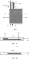
- FIG. 2a is a schematic diagram of a structure of a vapor chamber according to an embodiment of this application.
- FIG. 2b is an M-M cross-sectional view of the vapor chamber in FIG. 2a .
- the vapor chamber includes a first cover 101 close to a heat source, and a second cover 102 far from the heat source.
- the first cover 101 and the second cover 102 form a cavity.
- the vapor chamber is, for example, special-shaped, and the cavity is divided into at least a first cavity 100 and a second cavity 200.
- cross-sectional shapes of the first cavity 100 and the second cavity 200 are not limited.
- the cross-sectional shapes of the first cavity 100 and the second cavity 200 are rectangular, and the first cavity 100 and the second cavity 200 have different cross-sectional widths.
- the cross-sectional width of the second cavity 200 is greater than the cross-sectional width of the first cavity 100.
- the first cavity 200 is in a regular shape with a uniform cross-sectional width, so that first wicks can be evenly disposed at equal distances, to avoid obvious deterioration of thermal performance caused when a liquid working medium in a condensation zone cannot return due to a relatively large pressure difference between the first cavity and outside, or when a vapor cavity is blocked and vapor cannot return.
- the cross-sectional shape of the second cavity may alternatively be another regular polygon, a circle, or an irregular shape. Therefore, the second cavity may be in an irregular shape, to meet a heat dissipation requirement of a heat source in an irregular shape.
- the vapor chamber further includes, for example, a second wick 104.
- the second wick 104 uses a capillary structure, the capillary structure is filled with, for example, a cooling medium, and the cooling medium may be, for example, deionized water, methanol, or acetone.
- Heat dissipation of the vapor chamber may be implemented through a vapor-liquid phase change of the working medium. A specific heat dissipation principle and heat dissipation path of the vapor chamber are described above.
- the capillary structure may or may not be connected to an inner surface of a housing.
- the capillary structure is a porous medium whose material is metal.
- the material of the capillary structure is copper or a copper alloy, and the capillary structure may be, for example, one or more of copper mesh, copper fiber, copper powder, or copper foam. Alternatively, titanium or other non-metal materials may be used.
- the copper mesh may be bonded to surfaces of the first cover 101 and the second cover 102 opposite to each other by sintering, hot welding, cold pressing, or the like, to fix the copper mesh on the inner surface of the housing by sintering, hot welding, cold pressing, or the like, to prevent a position of the copper mesh from changing during use, thereby ensuring stability of product working.
- the copper mesh may be placed in a sealed cavity without any connection processing, to avoid impact of sintering, hot welding, cold pressing, or other processing on the housing, thereby ensuring structural stability of the housing.
- the sealed cavity of the vapor chamber is provided with an opening communicating with outside.
- the opening may be a liquid injection port or a vacuum port.
- the cooling medium is injected into the sealed cavity through the opening, the sealed cavity is vacuumized through the opening, and then the opening is sealed, so that the sealed cavity is in a vacuum negative pressure state.
- the sealed cavity is vacuumized inside, the injected cooling medium is in a negative pressure state, and once the cooling medium is heated in an evaporation zone, vaporization occurs.
- the vaporized cooling medium has a larger volume and fills the entire cavity.
- the cooling medium in a vapor state dissipates heat and is liquidized into a cooling medium in a liquid state, and the liquidized cooling medium returns to the evaporation zone via the capillary structure. In this way, a heat transfer cycle is formed in the sealed cavity.
- a specific structure of the vapor chamber is not limited in this embodiment of this application.
- the second wick 104 and the vapor cavity use a serial structure.
- the vapor chamber uses a serial structure and has a flexible shape.
- the structure is undiversified, and when the cross-sectional height is small, process difficulty in disposing the second wick 104 and the vapor cavity is increased.
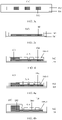
- FIG. 3 is a schematic diagram of a structure of another vapor chamber according to an embodiment of this application.
- FIG. 3a is an A-A cross-sectional view of the vapor chamber in FIG. 3.
- FIG. 3b is a B-B cross-sectional view of the vapor chamber in FIG. 3 .
- FIG. 3c is a C-C cross-sectional view of the vapor chamber in FIG. 3 .
- FIG. 3d is a D-D cross-sectional view of the vapor chamber in FIG. 3 .
- the vapor chamber includes a first cover 101 close to a heat source, and a second cover 102 far from the heat source. The first cover 101 and the second cover 102 form a cavity.
- the vapor chamber is divided into at least a first cavity 100 and a second cavity 200.
- the first cavity 100 and the second cavity 200 have different cross-sectional sizes. It should be noted that different cross-sectional sizes may be different cross-sectional widths or different cross-sectional heights.
- the first cavity 100 and the second cavity 200 have different cross-sectional widths. As shown in FIG. 3 , the cross-sectional width of the first cavity 100 is greater than the cross-sectional width of the second cavity 200. Certainly, the cross-sectional width of the second cavity 200 may alternatively be greater than the cross-sectional width of the first cavity 100.
- the first cavity 100 and the second cavity 200 have different cross-sectional heights.
- the cross-sectional height of the first cavity 100 is greater than the cross-sectional height of the second cavity 200.
- the cross-sectional height of the second cavity 200 may alternatively be greater than the cross-sectional height of the first cavity 100.
- a first wick 103 is disposed in the first cavity 100, and the first wick 103 has one end connected to the first cover 101 and the other end connected to the second cover 102.
- first wicks 103 There are a plurality of first wicks 103, the first wicks 103 are disposed in parallel, and the first cavity 100 is divided by the plurality of first wicks 103 into a plurality of first vapor cavities.
- the first wicks 103 and the first vapor cavities in the first cavity 100 use a parallel structure.
- a second wick 104 is disposed in the second cavity 200, and the second wick 104 is parallel to the first cover 101.
- One second wick 104 is disposed in the second cavity 200, the second wick 104 covers the first cover 101, and a cavity between the second wick 104 and the second upper cover forms a second vapor cavity.
- the second wick 104 and the second vapor cavity in the second cavity 200 use a serial structure.
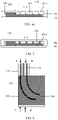
- the first wick 103 is connected to the second wick 104, and the first cavity 100 communicates with the second cavity 200.
- a working medium that is in the vapor chamber and that is close to a position of the heat source absorbs heat and then is vaporized quickly while taking away a large amount of heat. Then, with a latent heat property of vapor, when vapor in the vapor chamber diffuses from a high pressure zone close to the first cover 101 to a low pressure zone close to the second cover 102, and the vapor comes into contact with an inner wall of the second cover 102 at a lower temperature, the vapor is quickly condensed into a liquid state and releases thermal energy.
- the working medium condensed into the liquid state returns to the heat source under an action of a capillary force of the first wick 103 and the second wick 104. So far, a heat conduction cycle is completed, and a two-way circulation system in which vapor and liquid of the working medium coexist is formed.
- first wick 103 is connected to the second wick 104, and the first cavity 100 communicates with the second cavity 200, vapor can flow in the first cavity 100 and the second cavity 200.
- liquid working medium in the first wick 103 or the second wick 104 decreases, liquid in the second wick 104 and the first wick 103 can be transferred to each other under the action of the capillary force, thereby further improving heat equalizing performance of the vapor chamber.
- the vapor chamber may be designed into an irregular shape based on a product structure design.
- a part uses a parallel structure, so that a structure is simple, heat dissipation efficiency is high, and a cross-sectional height is low.
- Apart uses a serial structure, so that the vapor chamber of the serial structure may be made in an irregular shape.
- the vapor chamber uses a structure combining a serial structure and a parallel structure, which can support an irregular structure, and has better heat transfer performance while achieving thinning, thereby achieving thinning of the vapor chamber and improving heat transfer performance of an electronic device.
- a support column (105-1 or 105-2) is further disposed between the second cover 102 and the second wick 104, and the support column (105-1 or 105-2) is configured to support the second cover 102. Therefore, with the support column disposed, strength of an internal wall structure is ensured, and stability of the vapor chamber is improved.
- a structure of the support column is not limited in this application.
- the support column 105-1 and the second cover 102 are integrally formed. Therefore, stability of a connection between the support column 105-1 and the second cover 102 is improved, and safety performance of the vapor chamber is improved.
- the support column 105-1 is formed through stamping of the second cover 102.
- the support column 105-2 is a protrusion disposed on the second wick 104, and the support column 105-2 and the second wick 104 are integrally formed. Therefore, the support column 105-2 can be configured to not only support the second cover, but also serve as a wick, a connection between the support column 105-2 and the second wick is more stable, and when the support column 105-2 uses a same structure as the wick, heat equalizing performance of the vapor chamber can be improved.
- a cross section of the support column is in a circular, rectangular, or irregular shape. Therefore, the support column is more flexibly designed.
- the vapor chamber includes a first cover 101 close to a heat source, and a second cover 102 far from the heat source.
- the first cover 101 and the second cover 102 form a cavity.
- the vapor chamber is divided into at least a first cavity 100 and a second cavity 200, the first cavity 100 is disposed close to the heat source, and the first cavity 100 and the second cavity 200 have different cross-sectional widths.
- a first wick 103 is disposed in the first cavity 100, and the first wick 103 has one end connected to the first cover 101 and the other end connected to the second cover 102.
- first wicks 103 There are a plurality of first wicks 103, the first wicks 103 are disposed in parallel, and the first cavity 100 is divided by the plurality of first wicks 103 into a plurality of first vapor cavities.
- the first wicks 103 and the first vapor cavities in the first cavity 100 use a parallel structure.
- a second wick 104 is disposed in the second cavity 200, and the second wick 104 is parallel to the first cover 101.
- One second wick 104 is disposed in the second cavity 200, the second wick 104 covers the first cover 101, and a cavity between the second wick 104 and the second upper cover forms a second vapor cavity.
- the second wick 104 and the second vapor cavity in the second cavity 200 use a serial structure.
- a third wick 300 is further disposed in the second cavity 200, and the third wick 300 is connected to the first wick 103. Therefore, the third wick 300 may be connected to the first wick 103 and the second wick 104, so that heat in the first cavity can be better transferred to the second cavity, thereby further improving heat equalizing performance of the vapor chamber.
- the third wick 300 may have a same structure as the first wick 103 and the second wick 104.
- the third wick 300 may use a powder strip, a powder wall, or a woven structure. Therefore, product consistency is improved and a manufacturing process is simplified.
- materials of the wicks are not limited.
- the materials of the first wick 103 and the second wick 104 are, for example, copper, titanium, alloys, non-metal, or composite materials. Therefore, there are many choices for the materials of the first wick and the second wick, and process difficulty is relatively low.
- the first wick 103 and the second wick 104 use a capillary structure, and a manner of forming the capillary structure includes at least one of the following: weaving, sintering, or grooving. Therefore, a forming process of the first wick and the second wick is flexible, and a most appropriate process can be selected.
- the capillary structure may include particles such as copper powder/nickel powder/titanium powder, which may be sintered on the first cover 101 by sintering/electroplating/spraying/glue dispensing. Certainly, alternatively, the whole may be sintered and then copper powder/nickel powder/titanium powder is removed by secondary processing.
- a thickness of the vapor chamber is, for example, less than or equal to 0.3 mm.
- the first cover 101 and the second cover 102 may be manufactured by etching, stamping, or the like.
- the cross-sectional width of the first cavity 100 is less than the cross-sectional width of the second cavity 200, the first wicks 103 use a parallel structure, and the second wick 104 uses a serial structure.
- the cross-sectional width of the first cavity 100 is less than the cross-sectional width of the second cavity 200, the first wick 103 uses a serial structure, and the second wick 104 uses a parallel structure.
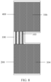
- the vapor chamber may be divided into more than two cavities. As shown in FIG. 8 , the vapor chamber includes a first cover 101 close to a heat source, and a second cover 102 far from the heat source. The first cover 101 and the second cover 102 form a cavity.
- the vapor chamber is divided into at least a first cavity 100, a second cavity 200, and a third cavity 400.
- a first wick 103 is disposed in the first cavity 100, and the first wick 103 has one end connected to the first cover 101 and the other end connected to the second cover 102.
- first wicks 103 There are a plurality of first wicks 103, the first wicks 103 are disposed in parallel, and the first cavity 100 is divided by the plurality of first wicks 103 into a plurality of first vapor cavities.
- the first wicks 103 and the first vapor cavities in the first cavity 100 use a parallel structure.
- a second wick 104 is disposed in the second cavity 200, and the second wick 104 is parallel to the first cover 101.
- One second wick 104 is disposed in the second cavity 200, the second wick 104 covers the first cover 101, and a cavity between the second wick 104 and the second upper cover forms a second vapor cavity.
- the second wick 104 and the second vapor cavity in the second cavity 200 use a serial structure.
- a third wick 106 is disposed in the third cavity 200, and the third wick 106 has a same structure as the second wick 104.
- the third wick is connected to the first wick and the second wick, and the third cavity communicates with the first cavity and the second cavity.
- the third wick may use a parallel structure. These all fall within the protection scope of this application.
- the vapor chamber is divided into a plurality of parts, and includes at least two types of internal structures, so that the vapor chamber has a more flexible structure, and an internal structure of the wick can be flexibly adjusted based on a shape of a heat source of a product, thereby improving temperature equalizing performance of the vapor chamber
- An embodiment of this application further provides an electronic device, including a heat source and the vapor chamber described above. Heat is conducted between the vapor chamber and the heat source. Therefore, with the foregoing structure, the vapor chamber has better heat equalizing performance, has a low cross-sectional height, and can be made in an irregular shape, to dissipate heat for an irregular heat source.
- the electronic device further includes a housing, and heat is conducted between the vapor chamber and the housing. Therefore, the vapor chamber can be attached to the housing, to improve heat equalizing performance of the housing.
Landscapes
- Engineering & Computer Science (AREA)
- Microelectronics & Electronic Packaging (AREA)
- Physics & Mathematics (AREA)
- Thermal Sciences (AREA)
- Mechanical Engineering (AREA)
- General Engineering & Computer Science (AREA)
- Life Sciences & Earth Sciences (AREA)
- Sustainable Development (AREA)
- Cooling Or The Like Of Electrical Apparatus (AREA)
- Cooling Or The Like Of Semiconductors Or Solid State Devices (AREA)
Priority Applications (1)
| Application Number | Priority Date | Filing Date | Title |
|---|---|---|---|
| EP25218491.6A EP4729872A2 (de) | 2020-06-01 | 2021-05-28 | Dampfkammer und elektronische vorrichtung |
Applications Claiming Priority (2)
| Application Number | Priority Date | Filing Date | Title |
|---|---|---|---|
| CN202010485885.4A CN113766796B (zh) | 2020-06-01 | 2020-06-01 | 均温板和电子设备 |
| PCT/CN2021/096985 WO2021244448A1 (zh) | 2020-06-01 | 2021-05-28 | 均温板和电子设备 |
Related Child Applications (1)
| Application Number | Title | Priority Date | Filing Date |
|---|---|---|---|
| EP25218491.6A Division EP4729872A2 (de) | 2020-06-01 | 2021-05-28 | Dampfkammer und elektronische vorrichtung |
Publications (4)
| Publication Number | Publication Date |
|---|---|
| EP4151944A1 true EP4151944A1 (de) | 2023-03-22 |
| EP4151944A4 EP4151944A4 (de) | 2023-11-15 |
| EP4151944B1 EP4151944B1 (de) | 2025-12-24 |
| EP4151944C0 EP4151944C0 (de) | 2025-12-24 |
Family
ID=78782689
Family Applications (2)
| Application Number | Title | Priority Date | Filing Date |
|---|---|---|---|
| EP21817356.5A Active EP4151944B1 (de) | 2020-06-01 | 2021-05-28 | Dampfkammer und elektronische vorrichtung |
| EP25218491.6A Pending EP4729872A2 (de) | 2020-06-01 | 2021-05-28 | Dampfkammer und elektronische vorrichtung |
Family Applications After (1)
| Application Number | Title | Priority Date | Filing Date |
|---|---|---|---|
| EP25218491.6A Pending EP4729872A2 (de) | 2020-06-01 | 2021-05-28 | Dampfkammer und elektronische vorrichtung |
Country Status (4)
| Country | Link |
|---|---|
| US (1) | US20230107867A1 (de) |
| EP (2) | EP4151944B1 (de) |
| CN (1) | CN113766796B (de) |
| WO (1) | WO2021244448A1 (de) |
Cited By (1)
| Publication number | Priority date | Publication date | Assignee | Title |
|---|---|---|---|---|
| WO2024219131A1 (ja) * | 2023-04-19 | 2024-10-24 | 株式会社村田製作所 | 熱拡散デバイス及び電子機器 |
Families Citing this family (6)
| Publication number | Priority date | Publication date | Assignee | Title |
|---|---|---|---|---|
| EP4114159A1 (de) * | 2021-06-29 | 2023-01-04 | Siemens Aktiengesellschaft | Vorrichtung zur wärmeableitung von in einem elektronikgehäuse angeordneten mikroelektronischen bauteilen |
| WO2023039881A1 (zh) * | 2021-09-18 | 2023-03-23 | 京东方科技集团股份有限公司 | 金属网格阵列及其制备方法、薄膜传感器及其制备方法 |
| CN115023099B (zh) * | 2021-11-10 | 2023-11-21 | 荣耀终端有限公司 | 电子设备 |
| CN117729733A (zh) * | 2022-09-09 | 2024-03-19 | 华为技术有限公司 | 一种均温板、电子设备以及芯片封装结构 |
| CN120434960B (zh) * | 2023-12-21 | 2026-03-10 | 荣耀终端股份有限公司 | 一种均温板以及电子设备 |
| CN120835500A (zh) * | 2025-03-21 | 2025-10-24 | 华为技术有限公司 | 一种均温板和电子设备 |
Family Cites Families (29)
| Publication number | Priority date | Publication date | Assignee | Title |
|---|---|---|---|---|
| US3587725A (en) * | 1968-10-16 | 1971-06-28 | Hughes Aircraft Co | Heat pipe having a substantially unidirectional thermal path |
| US3754594A (en) * | 1972-01-24 | 1973-08-28 | Sanders Associates Inc | Unilateral heat transfer apparatus |
| JP3654326B2 (ja) * | 1996-11-25 | 2005-06-02 | 株式会社デンソー | 沸騰冷却装置 |
| US6474074B2 (en) * | 2000-11-30 | 2002-11-05 | International Business Machines Corporation | Apparatus for dense chip packaging using heat pipes and thermoelectric coolers |
| CN101093151B (zh) * | 2006-06-21 | 2010-04-14 | 富准精密工业(深圳)有限公司 | 热管 |
| US20090025910A1 (en) * | 2007-07-27 | 2009-01-29 | Paul Hoffman | Vapor chamber structure with improved wick and method for manufacturing the same |
| US20090040726A1 (en) * | 2007-08-09 | 2009-02-12 | Paul Hoffman | Vapor chamber structure and method for manufacturing the same |
| CN101995183A (zh) * | 2009-08-19 | 2011-03-30 | 富准精密工业(深圳)有限公司 | 平板式热管 |
| CN102723316A (zh) * | 2011-03-29 | 2012-10-10 | 北京奇宏科技研发中心有限公司 | 环路热管结构 |
| CN104112724A (zh) * | 2013-04-22 | 2014-10-22 | 华硕电脑股份有限公司 | 散热元件 |
| US20150041103A1 (en) * | 2013-08-06 | 2015-02-12 | Aall Power Heatsinks, Inc. | Vapor chamber with improved wicking structure |
| US9247034B2 (en) * | 2013-08-22 | 2016-01-26 | Asia Vital Components Co., Ltd. | Heat dissipation structure and handheld electronic device with the heat dissipation structure |
| TWI582366B (zh) * | 2014-09-03 | 2017-05-11 | 奇鋐科技股份有限公司 | 均溫板結構 |
| US10502498B2 (en) * | 2015-07-20 | 2019-12-10 | Delta Electronics, Inc. | Slim vapor chamber |
| CN106376214B (zh) * | 2015-07-20 | 2019-06-07 | 台达电子工业股份有限公司 | 薄型均温板 |
| TWM533401U (en) * | 2016-06-21 | 2016-12-01 | Tai Sol Electronics Co Ltd | Heat dissipation apparatus |
| JP6623296B2 (ja) * | 2016-07-01 | 2019-12-18 | 古河電気工業株式会社 | ベーパーチャンバ |
| JPWO2018116951A1 (ja) * | 2016-12-20 | 2019-10-24 | 株式会社フジクラ | 放熱モジュール |
| TWI654404B (zh) * | 2017-05-05 | 2019-03-21 | 雙鴻科技股份有限公司 | 均溫板 |
| US10527355B2 (en) * | 2017-06-13 | 2020-01-07 | Microsoft Technology Licensing, Llc | Devices, methods, and systems for thermal management |
| JP6696631B2 (ja) * | 2017-09-29 | 2020-05-20 | 株式会社村田製作所 | ベーパーチャンバー |
| JP2021036175A (ja) * | 2017-09-29 | 2021-03-04 | 株式会社村田製作所 | ベーパーチャンバー |
| TWM562956U (zh) * | 2017-10-12 | 2018-07-01 | 泰碩電子股份有限公司 | 內凸紋構成流道之均溫板 |
| JP6588599B1 (ja) * | 2018-05-29 | 2019-10-09 | 古河電気工業株式会社 | ベーパーチャンバ |
| US11913725B2 (en) * | 2018-12-21 | 2024-02-27 | Cooler Master Co., Ltd. | Heat dissipation device having irregular shape |
| CN209281334U (zh) * | 2019-01-31 | 2019-08-20 | 泽鸿(广州)电子科技有限公司 | 均温板与具有该均温板的散热装置 |
| US11445636B2 (en) * | 2019-10-31 | 2022-09-13 | Murata Manufacturing Co., Ltd. | Vapor chamber, heatsink device, and electronic device |
| CN111194160A (zh) * | 2020-02-24 | 2020-05-22 | 北京中石伟业科技无锡有限公司 | 一种基于泡沫铜的超薄非对称均热板 |
| CN213343091U (zh) * | 2020-06-01 | 2021-06-01 | 华为技术有限公司 | 均温板和电子设备 |
-
2020
- 2020-06-01 CN CN202010485885.4A patent/CN113766796B/zh active Active
-
2021
- 2021-05-28 EP EP21817356.5A patent/EP4151944B1/de active Active
- 2021-05-28 EP EP25218491.6A patent/EP4729872A2/de active Pending
- 2021-05-28 WO PCT/CN2021/096985 patent/WO2021244448A1/zh not_active Ceased
-
2022
- 2022-12-01 US US18/073,307 patent/US20230107867A1/en active Pending
Cited By (1)
| Publication number | Priority date | Publication date | Assignee | Title |
|---|---|---|---|---|
| WO2024219131A1 (ja) * | 2023-04-19 | 2024-10-24 | 株式会社村田製作所 | 熱拡散デバイス及び電子機器 |
Also Published As
| Publication number | Publication date |
|---|---|
| EP4151944B1 (de) | 2025-12-24 |
| CN113766796B (zh) | 2025-03-04 |
| EP4729872A2 (de) | 2026-04-22 |
| US20230107867A1 (en) | 2023-04-06 |
| CN113766796A (zh) | 2021-12-07 |
| EP4151944A4 (de) | 2023-11-15 |
| EP4151944C0 (de) | 2025-12-24 |
| WO2021244448A1 (zh) | 2021-12-09 |
Similar Documents
| Publication | Publication Date | Title |
|---|---|---|
| EP4151944B1 (de) | Dampfkammer und elektronische vorrichtung | |
| EP4391043B1 (de) | Dampfkammer und elektronische vorrichtung | |
| EP3951864B1 (de) | Wärmeableitungsvorrichtung, leiterplatte und elektronisches gerät | |
| CN108700282B (zh) | 用于便携式应用的高性能两相冷却设备 | |
| CN113983843B (zh) | 薄板型环路热管 | |
| US20050173098A1 (en) | Three dimensional vapor chamber | |
| WO2021082414A1 (zh) | 一种均温部件及电子设备 | |
| US20020021556A1 (en) | Vapor chamber with integrated pin array | |
| US20100018678A1 (en) | Vapor Chamber with Boiling-Enhanced Multi-Wick Structure | |
| CN117529010B (zh) | 一种均热板及电子设备 | |
| JP7097308B2 (ja) | ウィック構造体及びウィック構造体を収容したヒートパイプ | |
| TWI773145B (zh) | 均溫板 | |
| EP3815815A1 (de) | Dampfkammer und kapillarfilm davon | |
| CN214582689U (zh) | 均温板 | |
| EP3986101A1 (de) | Wärmeleitungsvorrichtung und endgerät | |
| EP3971681B1 (de) | Wärmeleitendes element und elektronische vorrichtung | |
| TW202443094A (zh) | 均溫板裝置 | |
| TW202210779A (zh) | 均溫板 | |
| SG177233A1 (en) | Thermosyphon for cooling electronic components | |
| EP3579673B1 (de) | Wärmeleitende komponente und mobiles endgerät | |
| WO2019056506A1 (zh) | 由冲压工艺形成的薄型均热板 | |
| JP7260062B2 (ja) | 熱拡散デバイス | |
| CN103841803A (zh) | 利用厚过烧镀层和沸腾的具有薄腔的散热器 | |
| TWI801739B (zh) | 均溫板及其製造方法 | |
| RU2796496C1 (ru) | Мобильный терминал, испарительная камера и способ ее изготовления и электронное устройство |
Legal Events
| Date | Code | Title | Description |
|---|---|---|---|
| STAA | Information on the status of an ep patent application or granted ep patent |
Free format text: STATUS: THE INTERNATIONAL PUBLICATION HAS BEEN MADE |
|
| PUAI | Public reference made under article 153(3) epc to a published international application that has entered the european phase |
Free format text: ORIGINAL CODE: 0009012 |
|
| STAA | Information on the status of an ep patent application or granted ep patent |
Free format text: STATUS: REQUEST FOR EXAMINATION WAS MADE |
|
| 17P | Request for examination filed |
Effective date: 20221216 |
|
| AK | Designated contracting states |
Kind code of ref document: A1 Designated state(s): AL AT BE BG CH CY CZ DE DK EE ES FI FR GB GR HR HU IE IS IT LI LT LU LV MC MK MT NL NO PL PT RO RS SE SI SK SM TR |
|
| DAV | Request for validation of the european patent (deleted) | ||
| DAX | Request for extension of the european patent (deleted) | ||
| A4 | Supplementary search report drawn up and despatched |
Effective date: 20231018 |
|
| RIC1 | Information provided on ipc code assigned before grant |
Ipc: F28F 3/12 20060101ALI20231012BHEP Ipc: F28D 21/00 20060101ALI20231012BHEP Ipc: F28D 15/02 20060101ALI20231012BHEP Ipc: H05K 7/20 20060101ALI20231012BHEP Ipc: F28D 15/04 20060101AFI20231012BHEP |
|
| STAA | Information on the status of an ep patent application or granted ep patent |
Free format text: STATUS: EXAMINATION IS IN PROGRESS |
|
| 17Q | First examination report despatched |
Effective date: 20241216 |
|
| GRAP | Despatch of communication of intention to grant a patent |
Free format text: ORIGINAL CODE: EPIDOSNIGR1 |
|
| STAA | Information on the status of an ep patent application or granted ep patent |
Free format text: STATUS: GRANT OF PATENT IS INTENDED |
|
| INTG | Intention to grant announced |
Effective date: 20250820 |
|
| GRAS | Grant fee paid |
Free format text: ORIGINAL CODE: EPIDOSNIGR3 |
|
| GRAA | (expected) grant |
Free format text: ORIGINAL CODE: 0009210 |
|
| STAA | Information on the status of an ep patent application or granted ep patent |
Free format text: STATUS: THE PATENT HAS BEEN GRANTED |
|
| AK | Designated contracting states |
Kind code of ref document: B1 Designated state(s): AL AT BE BG CH CY CZ DE DK EE ES FI FR GB GR HR HU IE IS IT LI LT LU LV MC MK MT NL NO PL PT RO RS SE SI SK SM TR |
|
| REG | Reference to a national code |
Ref country code: CH Ref legal event code: F10 Free format text: ST27 STATUS EVENT CODE: U-0-0-F10-F00 (AS PROVIDED BY THE NATIONAL OFFICE) Effective date: 20251224 Ref country code: GB Ref legal event code: FG4D |
|
| REG | Reference to a national code |
Ref country code: DE Ref legal event code: R096 Ref document number: 602021045110 Country of ref document: DE |
|
| U01 | Request for unitary effect filed |
Effective date: 20251224 |
|
| U07 | Unitary effect registered |
Designated state(s): AT BE BG DE DK EE FI FR IT LT LU LV MT NL PT RO SE SI Effective date: 20260107 |
|
| PG25 | Lapsed in a contracting state [announced via postgrant information from national office to epo] |
Ref country code: NO Free format text: LAPSE BECAUSE OF FAILURE TO SUBMIT A TRANSLATION OF THE DESCRIPTION OR TO PAY THE FEE WITHIN THE PRESCRIBED TIME-LIMIT Effective date: 20260324 |
|
| PG25 | Lapsed in a contracting state [announced via postgrant information from national office to epo] |
Ref country code: HR Free format text: LAPSE BECAUSE OF FAILURE TO SUBMIT A TRANSLATION OF THE DESCRIPTION OR TO PAY THE FEE WITHIN THE PRESCRIBED TIME-LIMIT Effective date: 20251224 |
|
| PG25 | Lapsed in a contracting state [announced via postgrant information from national office to epo] |
Ref country code: RS Free format text: LAPSE BECAUSE OF FAILURE TO SUBMIT A TRANSLATION OF THE DESCRIPTION OR TO PAY THE FEE WITHIN THE PRESCRIBED TIME-LIMIT Effective date: 20260324 |