EP3971681B1 - Wärmeleitendes element und elektronische vorrichtung - Google Patents
Wärmeleitendes element und elektronische vorrichtung Download PDFInfo
- Publication number
- EP3971681B1 EP3971681B1 EP20815643.0A EP20815643A EP3971681B1 EP 3971681 B1 EP3971681 B1 EP 3971681B1 EP 20815643 A EP20815643 A EP 20815643A EP 3971681 B1 EP3971681 B1 EP 3971681B1
- Authority
- EP
- European Patent Office
- Prior art keywords
- plate body
- heat conducting
- cavity
- conducting part
- inner layer
- Prior art date
- Legal status (The legal status is an assumption and is not a legal conclusion. Google has not performed a legal analysis and makes no representation as to the accuracy of the status listed.)
- Active
Links
Images


Classifications
-
- F—MECHANICAL ENGINEERING; LIGHTING; HEATING; WEAPONS; BLASTING
- F28—HEAT EXCHANGE IN GENERAL
- F28D—HEAT-EXCHANGE APPARATUS, NOT PROVIDED FOR IN ANOTHER SUBCLASS, IN WHICH THE HEAT-EXCHANGE MEDIA DO NOT COME INTO DIRECT CONTACT
- F28D15/00—Heat-exchange apparatus with the intermediate heat-transfer medium in closed tubes passing into or through the conduit walls ; Heat-exchange apparatus employing intermediate heat-transfer medium or bodies
- F28D15/02—Heat-exchange apparatus with the intermediate heat-transfer medium in closed tubes passing into or through the conduit walls ; Heat-exchange apparatus employing intermediate heat-transfer medium or bodies in which the medium condenses and evaporates, e.g. heat pipes
- F28D15/0233—Heat-exchange apparatus with the intermediate heat-transfer medium in closed tubes passing into or through the conduit walls ; Heat-exchange apparatus employing intermediate heat-transfer medium or bodies in which the medium condenses and evaporates, e.g. heat pipes the conduits having a particular shape, e.g. non-circular cross-section, annular
-
- H—ELECTRICITY
- H05—ELECTRIC TECHNIQUES NOT OTHERWISE PROVIDED FOR
- H05K—PRINTED CIRCUITS; CASINGS OR CONSTRUCTIONAL DETAILS OF ELECTRIC APPARATUS; MANUFACTURE OF ASSEMBLAGES OF ELECTRICAL COMPONENTS
- H05K7/00—Constructional details common to different types of electric apparatus
- H05K7/20—Modifications to facilitate cooling, ventilating, or heating
- H05K7/2039—Modifications to facilitate cooling, ventilating, or heating characterised by the heat transfer by conduction from the heat generating element to a dissipating body
- H05K7/20436—Inner thermal coupling elements in heat dissipating housings, e.g. protrusions or depressions integrally formed in the housing
- H05K7/20445—Inner thermal coupling elements in heat dissipating housings, e.g. protrusions or depressions integrally formed in the housing the coupling element being an additional piece, e.g. thermal standoff
- H05K7/20472—Sheet interfaces
-
- F—MECHANICAL ENGINEERING; LIGHTING; HEATING; WEAPONS; BLASTING
- F28—HEAT EXCHANGE IN GENERAL
- F28D—HEAT-EXCHANGE APPARATUS, NOT PROVIDED FOR IN ANOTHER SUBCLASS, IN WHICH THE HEAT-EXCHANGE MEDIA DO NOT COME INTO DIRECT CONTACT
- F28D15/00—Heat-exchange apparatus with the intermediate heat-transfer medium in closed tubes passing into or through the conduit walls ; Heat-exchange apparatus employing intermediate heat-transfer medium or bodies
- F28D15/02—Heat-exchange apparatus with the intermediate heat-transfer medium in closed tubes passing into or through the conduit walls ; Heat-exchange apparatus employing intermediate heat-transfer medium or bodies in which the medium condenses and evaporates, e.g. heat pipes
- F28D15/04—Heat-exchange apparatus with the intermediate heat-transfer medium in closed tubes passing into or through the conduit walls ; Heat-exchange apparatus employing intermediate heat-transfer medium or bodies in which the medium condenses and evaporates, e.g. heat pipes with tubes having a capillary structure
- F28D15/046—Heat-exchange apparatus with the intermediate heat-transfer medium in closed tubes passing into or through the conduit walls ; Heat-exchange apparatus employing intermediate heat-transfer medium or bodies in which the medium condenses and evaporates, e.g. heat pipes with tubes having a capillary structure characterised by the material or the construction of the capillary structure
-
- F—MECHANICAL ENGINEERING; LIGHTING; HEATING; WEAPONS; BLASTING
- F28—HEAT EXCHANGE IN GENERAL
- F28F—DETAILS OF HEAT-EXCHANGE AND HEAT-TRANSFER APPARATUS, OF GENERAL APPLICATION
- F28F3/00—Plate-like or laminated elements; Assemblies of plate-like or laminated elements
- F28F3/12—Elements constructed in the shape of a hollow panel, e.g. with channels
-
- G—PHYSICS
- G06—COMPUTING OR CALCULATING; COUNTING
- G06F—ELECTRIC DIGITAL DATA PROCESSING
- G06F1/00—Details not covered by groups G06F3/00 - G06F13/00 and G06F21/00
- G06F1/16—Constructional details or arrangements
- G06F1/20—Cooling means
- G06F1/203—Cooling means for portable computers, e.g. for laptops
-
- H—ELECTRICITY
- H05—ELECTRIC TECHNIQUES NOT OTHERWISE PROVIDED FOR
- H05K—PRINTED CIRCUITS; CASINGS OR CONSTRUCTIONAL DETAILS OF ELECTRIC APPARATUS; MANUFACTURE OF ASSEMBLAGES OF ELECTRICAL COMPONENTS
- H05K7/00—Constructional details common to different types of electric apparatus
- H05K7/20—Modifications to facilitate cooling, ventilating, or heating
- H05K7/2029—Modifications to facilitate cooling, ventilating, or heating using a liquid coolant with phase change in electronic enclosures
- H05K7/20336—Heat pipes, e.g. wicks or capillary pumps
-
- F—MECHANICAL ENGINEERING; LIGHTING; HEATING; WEAPONS; BLASTING
- F28—HEAT EXCHANGE IN GENERAL
- F28D—HEAT-EXCHANGE APPARATUS, NOT PROVIDED FOR IN ANOTHER SUBCLASS, IN WHICH THE HEAT-EXCHANGE MEDIA DO NOT COME INTO DIRECT CONTACT
- F28D21/00—Heat-exchange apparatus not covered by any of the groups F28D1/00 - F28D20/00
- F28D2021/0019—Other heat exchangers for particular applications; Heat exchange systems not otherwise provided for
- F28D2021/0028—Other heat exchangers for particular applications; Heat exchange systems not otherwise provided for for cooling heat generating elements, e.g. for cooling electronic components or electric devices
- F28D2021/0029—Heat sinks
-
- F—MECHANICAL ENGINEERING; LIGHTING; HEATING; WEAPONS; BLASTING
- F28—HEAT EXCHANGE IN GENERAL
- F28F—DETAILS OF HEAT-EXCHANGE AND HEAT-TRANSFER APPARATUS, OF GENERAL APPLICATION
- F28F2225/00—Reinforcing means
- F28F2225/04—Reinforcing means for conduits
-
- G—PHYSICS
- G06—COMPUTING OR CALCULATING; COUNTING
- G06F—ELECTRIC DIGITAL DATA PROCESSING
- G06F2200/00—Indexing scheme relating to G06F1/04 - G06F1/32
- G06F2200/20—Indexing scheme relating to G06F1/20
- G06F2200/201—Cooling arrangements using cooling fluid
Definitions
- This application relates to the field of electronic device technologies, and in particular, to a heat conducting part and an electronic device.
- Electronic components such as a processor and a display card
- a heat pipe, a vapor chamber, a fan, and the like are usually disposed in the electronic device to dissipate heat of the electronic components.
- the vapor chamber is a vacuum cavity with a fine structure on an inner wall and is usually made of copper. Water is injected into the vacuum cavity to serve as cooling liquid.
- the cooling liquid in the cavity starts to be gasified after being heated in a low-vacuum-degree environment. At this moment, heat energy is absorbed, the volume is rapidly expanded, and the whole cavity is rapidly filled with a gas-phase cooling medium.
- the gas-phase working medium comes into contact with a cold area, a condensation phenomenon is resulted, heat accumulated during evaporation is released, and the condensed cooling liquid returns to the heat source through the fine structure. In this way, heat conduction is implemented in cycles.
- a conventional vapor chamber is made of copper, and therefore the vapor chamber has the disadvantage of a heavy weight, which is unfavorable for a lightweight design of the vapor chamber and the electronic device.
- a structure of a conventional heat pipe is similar to that of the vapor chamber, and the conventional heat pipe is also made of copper. Therefore, the heat pipe also has the disadvantage of a heavy weight, which is unfavorable for implementing the lightweight design of the vapor chamber and the electronic device.
- JP H11 30 4381 A describes a heat pipe with a coating layer of a material having corrosion resistance.
- JP 2002 022378 A describes a heat pipe comprising a clad material in which a copper-based material and an aluminium-based material are joined according to the preamble of claim 1.
- This application provides a heat conducting part with a relatively light weight and a long service life, and an electronic device.
- references to "one embodiment”, “some embodiments”, or the like described in the specification means that a particular feature, structure, or characteristic described in combination with the embodiment is included in one or more embodiments of this application. Therefore, phrases such as “in one embodiment”, “in some embodiments”, “in other embodiments”, and “in some other embodiments” in various places of this specification do not necessarily all refer to the same embodiment, but rather mean “one or more, but not all, embodiments", unless otherwise specifically emphasized.
- the terms such as “include”, “comprise”, “have”, and variations thereof all mean “include but not limited to", unless otherwise specifically emphasized.
- the heat conducting part provided in this application is applied to an electronic device and is used for conducting and diffusing heat generated by a heating element in the electronic device, so as to achieve a purpose of heat dissipation.
- the electronic device may be specifically a mobile phone, a tablet computer, a notebook computer, or the like.
- main heating elements in the notebook computer generally include a processor (central processing unit, CPU), a display chip (video chipset, GPU), and the like.
- CPU central processing unit
- display chip video chipset, GPU
- a large amount of heat is generated when the processor or the display chip runs. Therefore, in order to prevent working performance of the processor or the display chip from being affected by an excessively high temperature, a heat pipe, a vapor chamber, or the like is disposed in the notebook computer to serve as a heat conducting part and used for dissipating heat of the processor or the display chip.
- the whole vapor chamber is a plate-shaped structure and mainly includes two cover plates mutually sealed.
- a closed cavity is formed between the two cover plates, any one or a combination of a copper net, copper fiber, sintered copper powder, and a copper felt is disposed inside the cavity to serve as a capillary structure, and the cavity is filled with pure water to serve as cooling liquid.
- the two cover plates are usually made of oxygen-free copper.
- the working principle of the vapor chamber mainly includes four main steps of conduction, evaporation, convection and condensation.
- a heat source for example, one cover plate
- a cold source for example, the other cover plate
- Condensed water flows back to the heat source through the capillary structure, and a heat conduction cycle is completed.
- the two cover plates are both made of oxygen-free copper, and a relatively large density of the copper results in a relatively large weight of the whole vapor chamber, which is unfavorable for a lightweight design of the electronic device.
- Such disadvantage becomes more obvious for a portable electronic device, reducing portability of the electronic device and also degrading user experience.
- a working principle of the heat pipe is similar to that of the vapor chamber.
- the whole heat pipe is of a long-strip-shaped tubular structure, and the heat pipe has a closed cavity.
- a capillary structure tightly attached to an inner wall is also disposed in the cavity, and the cavity is filled with water, ethyl alcohol, or a mixed solution of the water and the ethyl alcohol to serve as cooling liquid.
- the heat pipe is usually made of copper.
- a relatively large density of the copper results in a relatively large weight of the whole heat pipe, which is unfavorable for the lightweight design of the electronic device. Such disadvantage becomes more obvious for a portable electronic device, reducing portability of the electronic device and also degrading user experience.
- an embodiment of this application provides a heat conducting part with a light weight, a long service life, and a high structural strength.
- the heat conducting part provided in this embodiment of this application includes a shell, a capillary structure, and cooling liquid.
- the shell includes an inner layer and an outer layer, where a cavity is enclosed by the inner layer, and the outer layer wraps a periphery of the inner layer.
- the capillary structure is disposed in the cavity and abuts against the shell.
- the cooling liquid is located in the cavity.
- the inner layer and the outer layer are made of different materials, and a material density of the outer layer is lower than a material density of the inner layer.
- the inner layer is made of copper or copper alloy; and the outer layer is made of aluminum, titanium, aluminum alloy, titanium alloy, or the like.
- a thickness ratio of the inner layer to the outer layer may be 1:1, 1:2, 2:1, or the like. That is, a thickness of the inner layer may be greater than, equal to, or less than a thickness of the outer layer; or an overall thickness of the inner layer may be the same or different; and correspondingly, an overall thickness of the outer layer may be the same or different.
- a material with a relatively large density and a stable chemical property may be selected for the inner layer to ensure durability of the heat conducting part; and a material with a relatively small density may be selected for the outer layer to ensure a structural strength of the shell and reduce an overall weight of the shell, or a material with better heat conducting performance is selected to improve the heat conducting performance of the heat conducting part.
- Combining the inner layer and the outer layer can not only ensure working stability of the heat conducting part, but also ensure the structural strength of the heat conducting part, to avoid damages caused by external force.
- the weight of the shell is effectively reduced, which is conducive to a lightweight design.
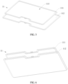
- the overall structure of the shell may be in a variety of forms, for example, may be plate-shaped, tubular, or in other shapes.
- the shell is of a plate-shaped structure.
- the shell is formed by buckling two plate bodies.
- the shell includes a first plate body 11 and a second plate body 12 that are buckled to each other, and the first plate body 11 and the second plate body 12 are buckled to each other to form the cavity.
- a manufacturing difficulty of the shell can be reduced, which helps reduce manufacturing costs.
- manufacturing quality of the shell can be ensured, thereby helping improve the working stability and the service life of the heat conducting part.
- the first plate body 11 and the second plate body 12 each are provided with the inner layer and the outer layer. Specifically, when the first plate body 11 and the second plate body 12 are buckled to each other, an edge of an inner layer 111 in the first plate body 11 is tightly fitted to an edge of an inner layer 121 in the second plate body 12, so as to form a closed cavity 13.
- the edge of the inner layer 111 is tightly fitted to the edge of the inner layer 121
- the edge of the outer layer 112 in the first plate body 11 may be tightly fitted to the edge of the outer layer 122 in the second plate body 12.
- the inner layers and the outer layers in the first plate body and the second plate body may have various types of structures and manufacturing processes.
- the inner layer 111 and the outer layer 112 in the first plate body 11 may be two separate plates.
- the inner layer 111 and the outer layer 112 of the first plate body 11 may be separately formed and then combined.
- the inner layer 111 may use a flat plate as a blank, and punching and cutting are performed on the blank according to needs, to obtain a formed inner layer.
- the outer layer 112 may use a flat plate as a blank, and punching and cutting are performed on the blank according to needs, to obtain a formed outer layer. Then, the formed inner layer and the formed outer layer are combined through processes such as pressing (hot pressing or cold pressing) or welding, so as to complete preparation of the first plate body 11.
- the inner layer 111 and the outer layer 112 may be first combined, and the first plate body 11 is then formed.
- the inner layer 111 may use a flat plate as a blank and the outer layer 112 may also use a flat plate as a blank; the blank of the inner layer and the blank of the outer layer are combined through processes such as pressing (hot pressing or cold pressing) or welding, so as to obtain a preformed first plate body; and then punching and cutting are performed on the preformed first plate body according to needs, to complete preparation of the first plate body 11.
- the cavity in the shell is formed by buckling the first plate body 11 and the second plate body 12, and therefore the inner layer of the first plate body and/or the inner layer of the second plate body are provided with a concave cavity structure, so as to form the cavity after the first plate body and the second plate body are buckled to each other.
- the concave cavity may be specifically formed in a variety of manners, for example, being formed in a punching manner or being formed in an etching and milling manner.
- a concave cavity 113 in the first plate body 11 is formed in the punching manner.
- the inner layer 111 and the outer layer 112 in the first plate body 11 may be punched separately, and then the inner layer 111 and the outer layer 112 that are formed by punching are combined, so as to complete preparation of the first plate body 11.
- the inner layer 111 and the outer layer 112 in the first plate body 11 may be first combined, and the first plate body 11 is then punched by using a punching process to form the concave cavity 113.
- the inner layer and the outer layer in the first plate body may be alternatively not two separate plates.
- the outer layer 112 of the first plate body 11 is a plate, and the inner layer 111 is directly formed on a surface of the outer layer 112 by using electroplating, vapor deposition, or other processes.
- the outer layer 112 may be treated by using processes such as punching, etching, and milling to form the concave cavity 113, and then the inner layer may be directly formed on a side of the concave cavity of the outer layer 112 in a manner such as electroplating or vapor deposition.
- a specific structure and manufacturing process of the second plate body may be roughly the same as those of the first plate body.
- a first plate body and a second plate body in a same shell may have substantially the same or different specific structures and manufacturing processes.
- the first plate and the second plate body in the shell may have a substantially same structure.
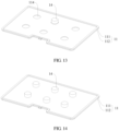
- the first plate body 11 and the second plate body 12 each are provided with a concave cavity structure, and after the first plate body 11 and the second plate body 12 are buckled to each other, the concave cavity structure located on the first plate body 11 and the concave cavity structure located on the second plate body 12 are buckled to each other to form the cavity 13.
- the structures of the first plate and the second plate body in the shell may be different.
- the first plate body 11 is provided with a concave cavity structure
- the second plate body 12 is provided with no concave cavity structure. After the first plate body 11 and the second plate body 12 are buckled to each other, the concave cavity structure located in the first plate body 11 is buckled to the concave cavity structure located in the second plate body 12 to form the cavity 13.
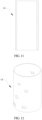
- the heat conducting part further includes at least one supporting column.
- the supporting column is disposed in the cavity and configured to support the cavity and prevent the cavity from being deformed by force and becoming smaller.
- the supporting column may be an independent structural part or may be a structure integrally formed with the first plate body or the second plate body in the shell.
- the supporting column 14 is an independent structural part; and one end of the supporting column 14 abuts against the first plate body 11, and the other end of the supporting column 14 abuts against the second plate body 12.
- the supporting column 14 may be a hollow structure with two closed ends; or as shown in FIG. 11 , the supporting column 14 may be a tubular structure.
- a peripheral surface of the supporting column 14 may be further provided in a hollowed-out shape.
- the inner wall or outer wall of the supporting column 14 may be further provided with a capillary structure, so as to implement backflow of the cooling liquid by using the capillary structure located on the supporting column 14.
- the capillary structure may be a long-strip-shaped groove or a long-strip-shaped protruding edge provided in the length direction of the supporting column.
- a locating slot 114 is provided in the first plate body 11, where a profile of the locating slot 114 may be slightly greater than or equal to a peripheral profile of the supporting column 14, or the profile of the locating slot 114 may be slightly less than the peripheral profile of the supporting column 14, so as to implement an interference fit between the locating slot 114 and the supporting column 14.
- the first plate body 11 may be horizontally placed with the inner layer 111 of the first plate body 11 facing upwards; a lower end of the supporting column 14 is inserted into the locating slot 114; the capillary structure is placed; and finally the first plate body and the second plate body are buckled, so that an upper end of the supporting column abuts against the inner layer of the second plate body.
- a locating slot is also provided in the second plate body, or locating slots are provided in both the first plate body and the second plate body, so as to improve a locating precision and connection stability between the supporting column and the shell.
- the supporting column may alternatively be connected to the shell.
- one end of the supporting column may be connected to the first plate body, and the other end of the supporting column may abut against the second plate body.
- one end of the supporting column may be connected to the second plate body, and the other end of the supporting column may abut against the first plate body.
- the supporting column may be connected to the first plate body or the second plate body in a welding or inserting manner.
- the supporting column may alternatively be a structure integrally formed with the shell.
- the supporting column may be a structure integrally formed with the first plate body, or may be a structure integrally formed with the second plate body.
- the supporting column 14 is a structure integrally formed with the first plate body 11.
- the first plate body 11 may be treated by using a punching process to form the supporting column 14. After the first plate body and the second plate body are buckled to each other, an extending end of the supporting column 14 abuts against the inner layer of the second plate body.
- the capillary structure needs to be installed between the first plate body and the second plate body before the first plate body and the second plate body are buckled.
- a proper assembling manner may be selected based on the specific structures of the first plate body and the second plate body.
- the capillary structure 15 may be placed on the first plate body 11 and abuts against the inner layer 111 of the first plate body 11; and then the second plate body 12 and the first plate body 11 are buckled tightly.
- the first plate body 11 and the second plate body 12 may be connected in a manner of welding, press-fit, or the like.
- gas in the cavity may be pumped out through the opening 115, so that the cavity is in a negative pressure state.
- the cooling liquid may be injected into the cavity through the opening 115. After the processes of vacuumizing and cooling liquid injection are completed, the opening 115 is sealed.
- the capillary structure 15 may be any one or a combination of a copper net, copper fiber, sintered copper powder and a copper felt.
- the capillary structure may be placed in the cavity and abuts against the first plate body 11 and the second plate body 12; or the capillary structure 15 is fixedly connected to the first plate body 11 and/or the second plate body 12.
- one plate surface is disposed close to the heat source or conductively comes in contact with the heat source.
- the first plate body 11 may be tightly close to the heat source or conductively come in contact with the heat source through heat-conducting silicone grease to implement fixed connection between the heat conducting part 1 and the heat source.
- an evaporation area is formed on one side of the first plate body 11, and a condensation area is formed on one side of the second plate body 12.
- the cooling liquid (a liquid cooling medium) in the cavity starts to be gasified after being heated in a low-vacuum-degree environment, and the whole cavity is rapidly filled with the gasified cooling medium.
- a gas-phase working medium comes in contact with the condensation area, the condensation phenomenon is resulted, and heat is released.
- the condensed cooling liquid flows back to the evaporation area through the capillary structure 15. In this way, heat conduction and dissipation is implemented in cycles.
- the heat conducting part is a long-strip-shaped tubular structure shown in FIG 17
- one end of the heat conducting part conductively comes in contact with the heat source to serve as the evaporation area, and the other end serves as the condensation area.
- one end of the heat conducting part 1 is disposed close to the heat source or conductively comes in contact with the heat source.
- the one end of the heat conducting part may be tightly close to the heat source or conductively come in contact with the heat source through heat-conducting silicone grease to implement fixed connection between the heat conducting part and the heat source.
- an evaporation area is formed at one end close to the heat source, and a condensation area is formed at the other end.
- the cooling liquid (a liquid cooling medium) in the cavity starts to be gasified after being heated in a low-vacuum-degree environment, and the whole cavity is rapidly filled with the gasified cooling medium.
- a gas-phase working medium comes in contact with the condensation area, the condensation phenomenon is resulted, and heat is released.
- the condensed cooling liquid flows back to the evaporation area through the capillary structure. In this way, heat conduction and dissipation is implemented in cycles.
- the capillary structure may be specifically a mesh structure similar to that in the embodiment described above, so that the cooling liquid flows back from the condensation area to the evaporation area of the heat conducting part.
- the capillary structure may alternatively be formed on a wall of the cavity.
- the capillary structure 15 is disposed on the inner wall of the cavity.
- the capillary structure 15 may be a structure capable of generating capillarity, such as a microgroove or a microprotrusion.
- an embodiment of this application further provides an electronic device, including an electric element 20 and the heat conducting part 1 in any one of the foregoing embodiments, where the heat conducting part 1 is conductively connected to the electric element 20.
- the electronic device further includes components such as a circuit board, a power supply module, and a screen.
- the electric element 20 may be installed on the circuit board and is configured to implement signal connection with other electric elements in the electronic device.
- the power supply module may supply or transmit electric energy to the electric element 20.
- the heat conducting part 1 may abut against the electric element 20, or is conductively connected to the electric element through an auxiliary material such as heat conducting silicone grease, so that heat generated by the electric element can be effectively transferred to the heat conducting part.
- the electronic device may be a tablet computer, a notebook computer, a mobile phone, or the like.
- the electric element may be a CPU, a GPU, or the like.
- the electronic device may be further provided with a fan, heat dissipation fins, and the like to dissipate heat for the heat conducting part, so as to improve heat dissipation effect of the electric element.
Landscapes
- Engineering & Computer Science (AREA)
- Physics & Mathematics (AREA)
- Thermal Sciences (AREA)
- General Engineering & Computer Science (AREA)
- Theoretical Computer Science (AREA)
- Microelectronics & Electronic Packaging (AREA)
- Mechanical Engineering (AREA)
- Life Sciences & Earth Sciences (AREA)
- Computer Hardware Design (AREA)
- Human Computer Interaction (AREA)
- General Physics & Mathematics (AREA)
- Sustainable Development (AREA)
- Cooling Or The Like Of Semiconductors Or Solid State Devices (AREA)
- Cooling Or The Like Of Electrical Apparatus (AREA)
Claims (11)
- Wärmeleitendes Teil, umfassend:eine Hülle, umfassend eine Innenschicht (111, 121) und eine Außenschicht (112, 122), wobei ein Hohlraum (13) von der Innenschicht (111, 121) umschlossen ist und die Außenschicht (112, 122) eine Peripherie der Innenschicht (111, 121) umhüllt;eine Kapillarstruktur, die im Hohlraum (13) angeordnet ist und an der Hülle anliegt; undKühlflüssigkeit, die sich im Hohlraum (13) befindet, wobeidie Innenschicht (111, 121) und die Außenschicht (112, 122) aus unterschiedlichen Materialien bestehen und eine Materialdichte der Außenschicht (112, 122) geringer als eine Materialdichte der Innenschicht (111, 121) ist;wobei die Hülle einen ersten Plattenkörper (11) und einen zweiten Plattenkörper (12) umfasst, die zusammengefügt sind; unddie Innenschicht (111, 121) sich jeweils auf einander zugewandten Plattenoberflächen des ersten Plattenkörpers (11) und des zweiten Plattenkörpers (12) befindet, die Außenschicht (112, 122) sich jeweils auf von einander abgewandten Plattenoberflächen des ersten Plattenkörpers (11) und des zweiten Plattenkörpers (12) befindet und der Hohlraum (13) sich zwischen der Innenschicht (111, 121) des ersten Plattenkörpers (11) und der Innenschicht (111, 121) des zweiten Plattenkörpers (12) befindet;dadurch gekennzeichnet, dass der erste Plattenkörper (11) und der zweite Plattenkörper (12) jeweils mit einer konkaven Hohlraumstruktur versehen sind, und nachdem der erste Plattenkörper (11) und der zweite Plattenkörper (12) zusammengefügt wurden, die konkave Hohlraumstruktur, die sich an dem ersten Plattenkörper (11) befindet, und die konkave Hohlraumstruktur, die sich an dem zweiten Plattenkörper (12) befindet, zusammengefügt sind, sodass sie den Hohlraum (13) bilden.
- Wärmeleitteil nach Anspruch 1, wobei die Innenschicht (111, 121) aus Kupfer oder einer Kupferlegierung besteht.
- Wärmeleitendes Teil nach Anspruch 1 oder 2, wobei die Außenschicht (112, 122) aus mindestens einem von Aluminium, Aluminiumlegierung, Titan und Titanlegierung besteht.
- Wärmeleitendes Teil nach Anspruch 3, wobei der erste Plattenkörper (11) mit einer Nut versehen ist, die entlang einer Richtung weg vom zweiten Plattenkörper (12) vertieft ist; und/oder der zweite Plattenkörper (12) mit einer Nut versehen ist, die entlang einer Richtung weg vom ersten Plattenkörper (11) vertieft ist.
- Wärmeleitendes Teil nach Anspruch 3 oder 4, wobei im Hohlraum (13) mindestens eine Stützsäule angeordnet ist; und
ein Ende der mindestens einen Stützsäule mit der Innenschicht (111, 121) des ersten Plattenkörpers (11) verbunden ist und das andere Ende der mindestens einen Stützsäule mit der Innenschicht (111, 121) des zweiten Plattenkörpers (12) verbunden ist. - Wärmeleitendes Teil nach Anspruch 1 oder 3, wobei im Hohlraum (13) mindestens eine Stützsäule angeordnet ist; und
die beiden Enden der mindestens einen Stützsäule mit der Hülle verbunden sind. - Wärmeleitendes Teil nach Anspruch 5 oder 6, wobei die mindestens eine Stützsäule nahe einem mittleren Teil des Hohlraums (13) angeordnet ist.
- Wärmeleitendes Teil nach einem der Ansprüche 5 bis 7, wobei in einer Innenwand des Hohlraums (13) eine Aufnahmenut vorgesehen ist; und
die beiden Enden der mindestens einen Stützsäule an der Aufnahmenut anliegen. - Wärmeleitendes Teil nach einem der Ansprüche 5 bis 7, wobei die Stützsäule eine einstückig mit der Hülle gebildete Struktur ist.
- Wärmeleitendes Teil nach einem der Ansprüche 1 bis 9, wobei die Kapillarstruktur eines von einem Kupfernetz, einer Kupferfaser, einem gesinterten Kupferpulver und einem Kupferfilz oder eine Kombination daraus ist.
- Elektronische Vorrichtung, umfassend eine Leiterplatte, ein auf der Leiterplatte installiertes elektrisches Element und das wärmeleitende Teil nach einem der Ansprüche 1 bis 10, wobei
der wärmeleitende Teil leitend mit dem elektrischen Element verbunden ist.
Applications Claiming Priority (2)
| Application Number | Priority Date | Filing Date | Title |
|---|---|---|---|
| CN201910456489.6A CN112015249A (zh) | 2019-05-29 | 2019-05-29 | 一种导热件及电子设备 |
| PCT/CN2020/092170 WO2020238865A1 (zh) | 2019-05-29 | 2020-05-25 | 一种导热件及电子设备 |
Publications (3)
| Publication Number | Publication Date |
|---|---|
| EP3971681A1 EP3971681A1 (de) | 2022-03-23 |
| EP3971681A4 EP3971681A4 (de) | 2022-06-15 |
| EP3971681B1 true EP3971681B1 (de) | 2024-06-19 |
Family
ID=73500774
Family Applications (1)
| Application Number | Title | Priority Date | Filing Date |
|---|---|---|---|
| EP20815643.0A Active EP3971681B1 (de) | 2019-05-29 | 2020-05-25 | Wärmeleitendes element und elektronische vorrichtung |
Country Status (4)
| Country | Link |
|---|---|
| US (1) | US20220087073A1 (de) |
| EP (1) | EP3971681B1 (de) |
| CN (1) | CN112015249A (de) |
| WO (1) | WO2020238865A1 (de) |
Families Citing this family (3)
| Publication number | Priority date | Publication date | Assignee | Title |
|---|---|---|---|---|
| CN115968159A (zh) * | 2021-10-11 | 2023-04-14 | 杭州本松新材料技术股份有限公司 | 一种电子设备散热外壳组件及含其的电子设备 |
| CN115334857A (zh) * | 2022-09-09 | 2022-11-11 | 维沃移动通信有限公司 | 均热板、电子设备和均热板的制造方法 |
| FR3147121B1 (fr) * | 2023-03-27 | 2025-12-26 | Commissariat Energie Atomique | Procede de fabrication d’une structure comprenant des cavites |
Family Cites Families (20)
| Publication number | Priority date | Publication date | Assignee | Title |
|---|---|---|---|---|
| US5880524A (en) * | 1997-05-05 | 1999-03-09 | Intel Corporation | Heat pipe lid for electronic packages |
| JPH11304381A (ja) * | 1998-04-23 | 1999-11-05 | Fujikura Ltd | ヒートパイプ |
| JP2002022378A (ja) * | 2000-07-06 | 2002-01-23 | Showa Denko Kk | ヒートパイプ |
| KR20030096234A (ko) * | 2000-11-13 | 2003-12-24 | 도요 고한 가부시키가이샤 | 중공 적층체 및 그것을 사용한 히트싱크 |
| US20050139995A1 (en) * | 2003-06-10 | 2005-06-30 | David Sarraf | CTE-matched heat pipe |
| TWI290612B (en) * | 2003-11-27 | 2007-12-01 | Lg Cable Ltd | Flat plate heat transfer device |
| CN100413061C (zh) * | 2004-06-07 | 2008-08-20 | 鸿富锦精密工业(深圳)有限公司 | 一种热管及其制造方法 |
| EP1896790A2 (de) * | 2005-06-24 | 2008-03-12 | Convergence Technologies Limited | Wärmeübertragungsvorrichtung |
| CN200966197Y (zh) * | 2006-05-12 | 2007-10-24 | 迈萪科技股份有限公司 | 具有复合式微结构的均热板 |
| US20090260785A1 (en) * | 2008-04-17 | 2009-10-22 | Wang Cheng-Tu | Heat plate with capillary supporting structure and manufacturing method thereof |
| US9664458B2 (en) * | 2014-12-25 | 2017-05-30 | Asia Vital Components Co., Ltd. | Supporting structure for vapor chamber |
| CN105352351B (zh) * | 2015-11-03 | 2018-07-06 | 刘树宇 | 一种均温板改进结构 |
| US10663231B2 (en) * | 2016-06-08 | 2020-05-26 | Delta Electronics, Inc. | Manufacturing method of heat conducting device |
| WO2018198375A1 (ja) * | 2017-04-28 | 2018-11-01 | 株式会社村田製作所 | ベーパーチャンバー |
| US20180361505A1 (en) * | 2017-06-19 | 2018-12-20 | Asia Vital Components Co., Ltd. | Manufacturing method of heat dissipation unit |
| JP2021036175A (ja) * | 2017-09-29 | 2021-03-04 | 株式会社村田製作所 | ベーパーチャンバー |
| CN108833646B (zh) * | 2018-04-25 | 2020-10-02 | 维沃移动通信有限公司 | 一种保护套 |
| CN111712681B (zh) * | 2018-07-31 | 2021-12-14 | 株式会社村田制作所 | 均热板 |
| CN111712682B (zh) * | 2018-07-31 | 2021-11-19 | 株式会社村田制作所 | 均热板 |
| US11573055B2 (en) * | 2019-12-27 | 2023-02-07 | Intel Corporation | Vapor chamber and means of attachment |
-
2019
- 2019-05-29 CN CN201910456489.6A patent/CN112015249A/zh active Pending
-
2020
- 2020-05-25 WO PCT/CN2020/092170 patent/WO2020238865A1/zh not_active Ceased
- 2020-05-25 EP EP20815643.0A patent/EP3971681B1/de active Active
-
2021
- 2021-11-29 US US17/536,672 patent/US20220087073A1/en not_active Abandoned
Also Published As
| Publication number | Publication date |
|---|---|
| CN112015249A (zh) | 2020-12-01 |
| WO2020238865A1 (zh) | 2020-12-03 |
| EP3971681A1 (de) | 2022-03-23 |
| EP3971681A4 (de) | 2022-06-15 |
| US20220087073A1 (en) | 2022-03-17 |
Similar Documents
| Publication | Publication Date | Title |
|---|---|---|
| EP3971681B1 (de) | Wärmeleitendes element und elektronische vorrichtung | |
| CN202135434U (zh) | 冷却装置、电子设备 | |
| CN110708934A (zh) | 一种均温部件及电子设备 | |
| TWI701992B (zh) | 均溫板 | |
| CN110572981B (zh) | 一种导热装置及终端设备 | |
| CN105940278A (zh) | 移动终端 | |
| CN110191626B (zh) | 壳体组件、其制备方法以及电子设备 | |
| CN211373312U (zh) | 均温板及其毛细薄片 | |
| WO2021083142A1 (zh) | 一种电子设备 | |
| CN114705071A (zh) | 移动终端、均温板和均温板的制作方法 | |
| CN112135488A (zh) | 导热结构及其制备方法、电子设备 | |
| CN212086656U (zh) | 具有散热结构的电子装置 | |
| CN113766796A (zh) | 均温板和电子设备 | |
| WO2019200882A1 (zh) | 一种散热构件及智能终端 | |
| CN112672604A (zh) | 均热板、外壳和电子装置 | |
| CN114466557A (zh) | 电子设备的壳体、电子设备以及电子设备的壳体制造方法 | |
| CN118158956A (zh) | 一种电子设备外壳及电子设备 | |
| CN108601286B (zh) | 电子设备 | |
| CN213343091U (zh) | 均温板和电子设备 | |
| TW202212763A (zh) | 均溫板 | |
| CN213244735U (zh) | 一种导热结构及其电子设备 | |
| CN210573485U (zh) | 便携式平板笔记本 | |
| CN215453703U (zh) | 均温板 | |
| TWI801739B (zh) | 均溫板及其製造方法 | |
| CN221829315U (zh) | 均热板及电子设备 |
Legal Events
| Date | Code | Title | Description |
|---|---|---|---|
| STAA | Information on the status of an ep patent application or granted ep patent |
Free format text: STATUS: THE INTERNATIONAL PUBLICATION HAS BEEN MADE |
|
| PUAI | Public reference made under article 153(3) epc to a published international application that has entered the european phase |
Free format text: ORIGINAL CODE: 0009012 |
|
| STAA | Information on the status of an ep patent application or granted ep patent |
Free format text: STATUS: REQUEST FOR EXAMINATION WAS MADE |
|
| 17P | Request for examination filed |
Effective date: 20211213 |
|
| AK | Designated contracting states |
Kind code of ref document: A1 Designated state(s): AL AT BE BG CH CY CZ DE DK EE ES FI FR GB GR HR HU IE IS IT LI LT LU LV MC MK MT NL NO PL PT RO RS SE SI SK SM TR |
|
| A4 | Supplementary search report drawn up and despatched |
Effective date: 20220518 |
|
| RIC1 | Information provided on ipc code assigned before grant |
Ipc: F28D 21/00 20060101ALI20220512BHEP Ipc: F28D 15/02 20060101ALI20220512BHEP Ipc: F28F 3/12 20060101ALI20220512BHEP Ipc: F28D 15/04 20060101ALI20220512BHEP Ipc: H05K 7/20 20060101ALI20220512BHEP Ipc: G06F 1/20 20060101AFI20220512BHEP |
|
| DAV | Request for validation of the european patent (deleted) | ||
| DAX | Request for extension of the european patent (deleted) | ||
| GRAP | Despatch of communication of intention to grant a patent |
Free format text: ORIGINAL CODE: EPIDOSNIGR1 |
|
| STAA | Information on the status of an ep patent application or granted ep patent |
Free format text: STATUS: GRANT OF PATENT IS INTENDED |
|
| INTG | Intention to grant announced |
Effective date: 20240201 |
|
| GRAS | Grant fee paid |
Free format text: ORIGINAL CODE: EPIDOSNIGR3 |
|
| GRAA | (expected) grant |
Free format text: ORIGINAL CODE: 0009210 |
|
| STAA | Information on the status of an ep patent application or granted ep patent |
Free format text: STATUS: THE PATENT HAS BEEN GRANTED |
|
| AK | Designated contracting states |
Kind code of ref document: B1 Designated state(s): AL AT BE BG CH CY CZ DE DK EE ES FI FR GB GR HR HU IE IS IT LI LT LU LV MC MK MT NL NO PL PT RO RS SE SI SK SM TR |
|
| REG | Reference to a national code |
Ref country code: GB Ref legal event code: FG4D |
|
| REG | Reference to a national code |
Ref country code: CH Ref legal event code: EP |
|
| REG | Reference to a national code |
Ref country code: DE Ref legal event code: R096 Ref document number: 602020032725 Country of ref document: DE |
|
| REG | Reference to a national code |
Ref country code: NL Ref legal event code: FP |
|
| PG25 | Lapsed in a contracting state [announced via postgrant information from national office to epo] |
Ref country code: BG Free format text: LAPSE BECAUSE OF FAILURE TO SUBMIT A TRANSLATION OF THE DESCRIPTION OR TO PAY THE FEE WITHIN THE PRESCRIBED TIME-LIMIT Effective date: 20240619 |
|
| PG25 | Lapsed in a contracting state [announced via postgrant information from national office to epo] |
Ref country code: HR Free format text: LAPSE BECAUSE OF FAILURE TO SUBMIT A TRANSLATION OF THE DESCRIPTION OR TO PAY THE FEE WITHIN THE PRESCRIBED TIME-LIMIT Effective date: 20240619 Ref country code: FI Free format text: LAPSE BECAUSE OF FAILURE TO SUBMIT A TRANSLATION OF THE DESCRIPTION OR TO PAY THE FEE WITHIN THE PRESCRIBED TIME-LIMIT Effective date: 20240619 |
|
| REG | Reference to a national code |
Ref country code: LT Ref legal event code: MG9D |
|
| PG25 | Lapsed in a contracting state [announced via postgrant information from national office to epo] |
Ref country code: GR Free format text: LAPSE BECAUSE OF FAILURE TO SUBMIT A TRANSLATION OF THE DESCRIPTION OR TO PAY THE FEE WITHIN THE PRESCRIBED TIME-LIMIT Effective date: 20240920 |
|
| PG25 | Lapsed in a contracting state [announced via postgrant information from national office to epo] |
Ref country code: LV Free format text: LAPSE BECAUSE OF FAILURE TO SUBMIT A TRANSLATION OF THE DESCRIPTION OR TO PAY THE FEE WITHIN THE PRESCRIBED TIME-LIMIT Effective date: 20240619 |
|
| PG25 | Lapsed in a contracting state [announced via postgrant information from national office to epo] |
Ref country code: NO Free format text: LAPSE BECAUSE OF FAILURE TO SUBMIT A TRANSLATION OF THE DESCRIPTION OR TO PAY THE FEE WITHIN THE PRESCRIBED TIME-LIMIT Effective date: 20240919 Ref country code: LV Free format text: LAPSE BECAUSE OF FAILURE TO SUBMIT A TRANSLATION OF THE DESCRIPTION OR TO PAY THE FEE WITHIN THE PRESCRIBED TIME-LIMIT Effective date: 20240619 Ref country code: HR Free format text: LAPSE BECAUSE OF FAILURE TO SUBMIT A TRANSLATION OF THE DESCRIPTION OR TO PAY THE FEE WITHIN THE PRESCRIBED TIME-LIMIT Effective date: 20240619 Ref country code: GR Free format text: LAPSE BECAUSE OF FAILURE TO SUBMIT A TRANSLATION OF THE DESCRIPTION OR TO PAY THE FEE WITHIN THE PRESCRIBED TIME-LIMIT Effective date: 20240920 Ref country code: FI Free format text: LAPSE BECAUSE OF FAILURE TO SUBMIT A TRANSLATION OF THE DESCRIPTION OR TO PAY THE FEE WITHIN THE PRESCRIBED TIME-LIMIT Effective date: 20240619 Ref country code: BG Free format text: LAPSE BECAUSE OF FAILURE TO SUBMIT A TRANSLATION OF THE DESCRIPTION OR TO PAY THE FEE WITHIN THE PRESCRIBED TIME-LIMIT Effective date: 20240619 Ref country code: RS Free format text: LAPSE BECAUSE OF FAILURE TO SUBMIT A TRANSLATION OF THE DESCRIPTION OR TO PAY THE FEE WITHIN THE PRESCRIBED TIME-LIMIT Effective date: 20240919 |
|
| REG | Reference to a national code |
Ref country code: AT Ref legal event code: MK05 Ref document number: 1696321 Country of ref document: AT Kind code of ref document: T Effective date: 20240619 |
|
| PG25 | Lapsed in a contracting state [announced via postgrant information from national office to epo] |
Ref country code: PT Free format text: LAPSE BECAUSE OF FAILURE TO SUBMIT A TRANSLATION OF THE DESCRIPTION OR TO PAY THE FEE WITHIN THE PRESCRIBED TIME-LIMIT Effective date: 20241021 |
|
| PG25 | Lapsed in a contracting state [announced via postgrant information from national office to epo] |
Ref country code: PT Free format text: LAPSE BECAUSE OF FAILURE TO SUBMIT A TRANSLATION OF THE DESCRIPTION OR TO PAY THE FEE WITHIN THE PRESCRIBED TIME-LIMIT Effective date: 20241021 |
|
| PG25 | Lapsed in a contracting state [announced via postgrant information from national office to epo] |
Ref country code: PL Free format text: LAPSE BECAUSE OF FAILURE TO SUBMIT A TRANSLATION OF THE DESCRIPTION OR TO PAY THE FEE WITHIN THE PRESCRIBED TIME-LIMIT Effective date: 20240619 |
|
| PG25 | Lapsed in a contracting state [announced via postgrant information from national office to epo] |
Ref country code: EE Free format text: LAPSE BECAUSE OF FAILURE TO SUBMIT A TRANSLATION OF THE DESCRIPTION OR TO PAY THE FEE WITHIN THE PRESCRIBED TIME-LIMIT Effective date: 20240619 |
|
| PG25 | Lapsed in a contracting state [announced via postgrant information from national office to epo] |
Ref country code: AT Free format text: LAPSE BECAUSE OF FAILURE TO SUBMIT A TRANSLATION OF THE DESCRIPTION OR TO PAY THE FEE WITHIN THE PRESCRIBED TIME-LIMIT Effective date: 20240619 Ref country code: IS Free format text: LAPSE BECAUSE OF FAILURE TO SUBMIT A TRANSLATION OF THE DESCRIPTION OR TO PAY THE FEE WITHIN THE PRESCRIBED TIME-LIMIT Effective date: 20241019 |
|
| PG25 | Lapsed in a contracting state [announced via postgrant information from national office to epo] |
Ref country code: CZ Free format text: LAPSE BECAUSE OF FAILURE TO SUBMIT A TRANSLATION OF THE DESCRIPTION OR TO PAY THE FEE WITHIN THE PRESCRIBED TIME-LIMIT Effective date: 20240619 |
|
| PG25 | Lapsed in a contracting state [announced via postgrant information from national office to epo] |
Ref country code: SK Free format text: LAPSE BECAUSE OF FAILURE TO SUBMIT A TRANSLATION OF THE DESCRIPTION OR TO PAY THE FEE WITHIN THE PRESCRIBED TIME-LIMIT Effective date: 20240619 Ref country code: RO Free format text: LAPSE BECAUSE OF FAILURE TO SUBMIT A TRANSLATION OF THE DESCRIPTION OR TO PAY THE FEE WITHIN THE PRESCRIBED TIME-LIMIT Effective date: 20240619 |
|
| PG25 | Lapsed in a contracting state [announced via postgrant information from national office to epo] |
Ref country code: SM Free format text: LAPSE BECAUSE OF FAILURE TO SUBMIT A TRANSLATION OF THE DESCRIPTION OR TO PAY THE FEE WITHIN THE PRESCRIBED TIME-LIMIT Effective date: 20240619 Ref country code: ES Free format text: LAPSE BECAUSE OF FAILURE TO SUBMIT A TRANSLATION OF THE DESCRIPTION OR TO PAY THE FEE WITHIN THE PRESCRIBED TIME-LIMIT Effective date: 20240619 |
|
| PG25 | Lapsed in a contracting state [announced via postgrant information from national office to epo] |
Ref country code: SM Free format text: LAPSE BECAUSE OF FAILURE TO SUBMIT A TRANSLATION OF THE DESCRIPTION OR TO PAY THE FEE WITHIN THE PRESCRIBED TIME-LIMIT Effective date: 20240619 Ref country code: SK Free format text: LAPSE BECAUSE OF FAILURE TO SUBMIT A TRANSLATION OF THE DESCRIPTION OR TO PAY THE FEE WITHIN THE PRESCRIBED TIME-LIMIT Effective date: 20240619 Ref country code: RO Free format text: LAPSE BECAUSE OF FAILURE TO SUBMIT A TRANSLATION OF THE DESCRIPTION OR TO PAY THE FEE WITHIN THE PRESCRIBED TIME-LIMIT Effective date: 20240619 Ref country code: PL Free format text: LAPSE BECAUSE OF FAILURE TO SUBMIT A TRANSLATION OF THE DESCRIPTION OR TO PAY THE FEE WITHIN THE PRESCRIBED TIME-LIMIT Effective date: 20240619 Ref country code: IS Free format text: LAPSE BECAUSE OF FAILURE TO SUBMIT A TRANSLATION OF THE DESCRIPTION OR TO PAY THE FEE WITHIN THE PRESCRIBED TIME-LIMIT Effective date: 20241019 Ref country code: ES Free format text: LAPSE BECAUSE OF FAILURE TO SUBMIT A TRANSLATION OF THE DESCRIPTION OR TO PAY THE FEE WITHIN THE PRESCRIBED TIME-LIMIT Effective date: 20240619 Ref country code: EE Free format text: LAPSE BECAUSE OF FAILURE TO SUBMIT A TRANSLATION OF THE DESCRIPTION OR TO PAY THE FEE WITHIN THE PRESCRIBED TIME-LIMIT Effective date: 20240619 Ref country code: CZ Free format text: LAPSE BECAUSE OF FAILURE TO SUBMIT A TRANSLATION OF THE DESCRIPTION OR TO PAY THE FEE WITHIN THE PRESCRIBED TIME-LIMIT Effective date: 20240619 Ref country code: AT Free format text: LAPSE BECAUSE OF FAILURE TO SUBMIT A TRANSLATION OF THE DESCRIPTION OR TO PAY THE FEE WITHIN THE PRESCRIBED TIME-LIMIT Effective date: 20240619 |
|
| PG25 | Lapsed in a contracting state [announced via postgrant information from national office to epo] |
Ref country code: IT Free format text: LAPSE BECAUSE OF FAILURE TO SUBMIT A TRANSLATION OF THE DESCRIPTION OR TO PAY THE FEE WITHIN THE PRESCRIBED TIME-LIMIT Effective date: 20240619 |
|
| REG | Reference to a national code |
Ref country code: DE Ref legal event code: R097 Ref document number: 602020032725 Country of ref document: DE |
|
| PG25 | Lapsed in a contracting state [announced via postgrant information from national office to epo] |
Ref country code: DK Free format text: LAPSE BECAUSE OF FAILURE TO SUBMIT A TRANSLATION OF THE DESCRIPTION OR TO PAY THE FEE WITHIN THE PRESCRIBED TIME-LIMIT Effective date: 20240619 |
|
| PLBE | No opposition filed within time limit |
Free format text: ORIGINAL CODE: 0009261 |
|
| STAA | Information on the status of an ep patent application or granted ep patent |
Free format text: STATUS: NO OPPOSITION FILED WITHIN TIME LIMIT |
|
| PGFP | Annual fee paid to national office [announced via postgrant information from national office to epo] |
Ref country code: NL Payment date: 20250409 Year of fee payment: 6 |
|
| 26N | No opposition filed |
Effective date: 20250320 |
|
| PGFP | Annual fee paid to national office [announced via postgrant information from national office to epo] |
Ref country code: DE Payment date: 20250402 Year of fee payment: 6 |
|
| PG25 | Lapsed in a contracting state [announced via postgrant information from national office to epo] |
Ref country code: SE Free format text: LAPSE BECAUSE OF FAILURE TO SUBMIT A TRANSLATION OF THE DESCRIPTION OR TO PAY THE FEE WITHIN THE PRESCRIBED TIME-LIMIT Effective date: 20240619 |
|
| REG | Reference to a national code |
Ref country code: CH Ref legal event code: H13 Free format text: ST27 STATUS EVENT CODE: U-0-0-H10-H13 (AS PROVIDED BY THE NATIONAL OFFICE) Effective date: 20251223 |
|
| PG25 | Lapsed in a contracting state [announced via postgrant information from national office to epo] |
Ref country code: LU Free format text: LAPSE BECAUSE OF NON-PAYMENT OF DUE FEES Effective date: 20250525 |
|
| PG25 | Lapsed in a contracting state [announced via postgrant information from national office to epo] |
Ref country code: CH Free format text: LAPSE BECAUSE OF NON-PAYMENT OF DUE FEES Effective date: 20250531 |
|
| GBPC | Gb: european patent ceased through non-payment of renewal fee |
Effective date: 20250525 |
|
| REG | Reference to a national code |
Ref country code: BE Ref legal event code: MM Effective date: 20250531 |
|
| PG25 | Lapsed in a contracting state [announced via postgrant information from national office to epo] |
Ref country code: MC Free format text: LAPSE BECAUSE OF FAILURE TO SUBMIT A TRANSLATION OF THE DESCRIPTION OR TO PAY THE FEE WITHIN THE PRESCRIBED TIME-LIMIT Effective date: 20240619 |