EP4151420B1 - Verfahren zur bildkorrektur und druckvorrichtung - Google Patents
Verfahren zur bildkorrektur und druckvorrichtung Download PDFInfo
- Publication number
- EP4151420B1 EP4151420B1 EP22187830.9A EP22187830A EP4151420B1 EP 4151420 B1 EP4151420 B1 EP 4151420B1 EP 22187830 A EP22187830 A EP 22187830A EP 4151420 B1 EP4151420 B1 EP 4151420B1
- Authority
- EP
- European Patent Office
- Prior art keywords
- nozzles
- ink jet
- drive elements
- voltage
- power supply
- Prior art date
- Legal status (The legal status is an assumption and is not a legal conclusion. Google has not performed a legal analysis and makes no representation as to the accuracy of the status listed.)
- Active
Links
Images


Classifications
-
- B—PERFORMING OPERATIONS; TRANSPORTING
- B41—PRINTING; LINING MACHINES; TYPEWRITERS; STAMPS
- B41J—TYPEWRITERS; SELECTIVE PRINTING MECHANISMS, i.e. MECHANISMS PRINTING OTHERWISE THAN FROM A FORME; CORRECTION OF TYPOGRAPHICAL ERRORS
- B41J2/00—Typewriters or selective printing mechanisms characterised by the printing or marking process for which they are designed
- B41J2/005—Typewriters or selective printing mechanisms characterised by the printing or marking process for which they are designed characterised by bringing liquid or particles selectively into contact with a printing material
- B41J2/01—Ink jet
- B41J2/21—Ink jet for multi-colour printing
- B41J2/2132—Print quality control characterised by dot disposition, e.g. for reducing white stripes or banding
- B41J2/2146—Print quality control characterised by dot disposition, e.g. for reducing white stripes or banding for line print heads
-
- B—PERFORMING OPERATIONS; TRANSPORTING
- B41—PRINTING; LINING MACHINES; TYPEWRITERS; STAMPS
- B41J—TYPEWRITERS; SELECTIVE PRINTING MECHANISMS, i.e. MECHANISMS PRINTING OTHERWISE THAN FROM A FORME; CORRECTION OF TYPOGRAPHICAL ERRORS
- B41J2/00—Typewriters or selective printing mechanisms characterised by the printing or marking process for which they are designed
- B41J2/005—Typewriters or selective printing mechanisms characterised by the printing or marking process for which they are designed characterised by bringing liquid or particles selectively into contact with a printing material
- B41J2/01—Ink jet
- B41J2/015—Ink jet characterised by the jet generation process
- B41J2/04—Ink jet characterised by the jet generation process generating single droplets or particles on demand
- B41J2/045—Ink jet characterised by the jet generation process generating single droplets or particles on demand by pressure, e.g. electromechanical transducers
- B41J2/04501—Control methods or devices therefor, e.g. driver circuits, control circuits
- B41J2/04508—Control methods or devices therefor, e.g. driver circuits, control circuits aiming at correcting other parameters
-
- B—PERFORMING OPERATIONS; TRANSPORTING
- B41—PRINTING; LINING MACHINES; TYPEWRITERS; STAMPS
- B41J—TYPEWRITERS; SELECTIVE PRINTING MECHANISMS, i.e. MECHANISMS PRINTING OTHERWISE THAN FROM A FORME; CORRECTION OF TYPOGRAPHICAL ERRORS
- B41J2/00—Typewriters or selective printing mechanisms characterised by the printing or marking process for which they are designed
- B41J2/005—Typewriters or selective printing mechanisms characterised by the printing or marking process for which they are designed characterised by bringing liquid or particles selectively into contact with a printing material
- B41J2/01—Ink jet
- B41J2/015—Ink jet characterised by the jet generation process
- B41J2/04—Ink jet characterised by the jet generation process generating single droplets or particles on demand
- B41J2/045—Ink jet characterised by the jet generation process generating single droplets or particles on demand by pressure, e.g. electromechanical transducers
- B41J2/04501—Control methods or devices therefor, e.g. driver circuits, control circuits
- B41J2/04541—Specific driving circuit
-
- B—PERFORMING OPERATIONS; TRANSPORTING
- B41—PRINTING; LINING MACHINES; TYPEWRITERS; STAMPS
- B41J—TYPEWRITERS; SELECTIVE PRINTING MECHANISMS, i.e. MECHANISMS PRINTING OTHERWISE THAN FROM A FORME; CORRECTION OF TYPOGRAPHICAL ERRORS
- B41J2/00—Typewriters or selective printing mechanisms characterised by the printing or marking process for which they are designed
- B41J2/005—Typewriters or selective printing mechanisms characterised by the printing or marking process for which they are designed characterised by bringing liquid or particles selectively into contact with a printing material
- B41J2/01—Ink jet
- B41J2/015—Ink jet characterised by the jet generation process
- B41J2/04—Ink jet characterised by the jet generation process generating single droplets or particles on demand
- B41J2/045—Ink jet characterised by the jet generation process generating single droplets or particles on demand by pressure, e.g. electromechanical transducers
- B41J2/04501—Control methods or devices therefor, e.g. driver circuits, control circuits
- B41J2/04548—Details of power line section of control circuit
-
- B—PERFORMING OPERATIONS; TRANSPORTING
- B41—PRINTING; LINING MACHINES; TYPEWRITERS; STAMPS
- B41J—TYPEWRITERS; SELECTIVE PRINTING MECHANISMS, i.e. MECHANISMS PRINTING OTHERWISE THAN FROM A FORME; CORRECTION OF TYPOGRAPHICAL ERRORS
- B41J2/00—Typewriters or selective printing mechanisms characterised by the printing or marking process for which they are designed
- B41J2/005—Typewriters or selective printing mechanisms characterised by the printing or marking process for which they are designed characterised by bringing liquid or particles selectively into contact with a printing material
- B41J2/01—Ink jet
- B41J2/015—Ink jet characterised by the jet generation process
- B41J2/04—Ink jet characterised by the jet generation process generating single droplets or particles on demand
- B41J2/045—Ink jet characterised by the jet generation process generating single droplets or particles on demand by pressure, e.g. electromechanical transducers
- B41J2/04501—Control methods or devices therefor, e.g. driver circuits, control circuits
- B41J2/04581—Control methods or devices therefor, e.g. driver circuits, control circuits controlling heads based on piezoelectric elements
-
- B—PERFORMING OPERATIONS; TRANSPORTING
- B41—PRINTING; LINING MACHINES; TYPEWRITERS; STAMPS
- B41J—TYPEWRITERS; SELECTIVE PRINTING MECHANISMS, i.e. MECHANISMS PRINTING OTHERWISE THAN FROM A FORME; CORRECTION OF TYPOGRAPHICAL ERRORS
- B41J2/00—Typewriters or selective printing mechanisms characterised by the printing or marking process for which they are designed
- B41J2/005—Typewriters or selective printing mechanisms characterised by the printing or marking process for which they are designed characterised by bringing liquid or particles selectively into contact with a printing material
- B41J2/01—Ink jet
- B41J2/205—Ink jet for printing a discrete number of tones
- B41J2/2056—Ink jet for printing a discrete number of tones by ink density change
-
- B—PERFORMING OPERATIONS; TRANSPORTING
- B41—PRINTING; LINING MACHINES; TYPEWRITERS; STAMPS
- B41J—TYPEWRITERS; SELECTIVE PRINTING MECHANISMS, i.e. MECHANISMS PRINTING OTHERWISE THAN FROM A FORME; CORRECTION OF TYPOGRAPHICAL ERRORS
- B41J2/00—Typewriters or selective printing mechanisms characterised by the printing or marking process for which they are designed
- B41J2/005—Typewriters or selective printing mechanisms characterised by the printing or marking process for which they are designed characterised by bringing liquid or particles selectively into contact with a printing material
- B41J2/01—Ink jet
- B41J2/21—Ink jet for multi-colour printing
- B41J2/2121—Ink jet for multi-colour printing characterised by dot size, e.g. combinations of printed dots of different diameter
- B41J2/2128—Ink jet for multi-colour printing characterised by dot size, e.g. combinations of printed dots of different diameter by means of energy modulation
Definitions
- the invention relates to a method for correcting an image according to claim 1, and relates to a printing apparatus according to claim 9.
- JP2007030503A discloses an image forming device and method for forming image.
- the invention which was made in order to solve the above-described kind of problem, has an object of providing technology by which, in a printing apparatus including a plurality of ink jet heads, density differences in printed images occurring among the ink jet heads are corrected while minimizing image quality degradation.
- the first and second aspects of the present invention make possible that, in a printing apparatus comprising a plurality of ink jet heads, differences in density of printed image occurring among the ink jet heads are corrected while lowering of image quality is suppressed.
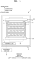
- a printing apparatus according to an embodiment of the present invention will be described below with reference to FIGS. 1 to 10 .
- an upstream side in a conveying direction of a print medium M is defined as a front side of a printing apparatus 1
- a downstream side in the conveying direction of the print medium M is defined as a rear side of the printing apparatus 1.
- a direction parallel to a plane along which the print medium M is conveyed is defined as a medium width direction.
- a left side in FIG. 1 is a left side of the printing apparatus 1
- a right side in FIG. 1 is a right side of the printing apparatus 1.
- a direction orthogonal to a conveying surface of the print medium M (a direction orthogonal to the paper surface of FIG.
- the medium width direction is one example of a "first direction” of the present teaching
- the conveying direction is one example of a "second direction" of the present teaching.
- the printing apparatus 1 includes a casing 2, a platen 3, four line heads 4, two conveying rollers 5A, 5B, and a controller 7.
- the print medium M such as paper, for example, is conveyed on an upper surface of the platen 3.
- the four line heads 4 are parallelly arranged in a front-rear direction above the platen 3.
- the two conveying rollers 5A, 5B are respectively disposed on a front side and rear side of the platen 3.
- the two conveying rollers 5A, 5B which are each driven by an unillustrated motor, convey rearwards the print medium M on the platen 3.
- the number of line heads 4 is not limited to four.
- the controller 7 includes a first board 71.
- the first board 71 includes an FPGA (Field Programmable Gate Array) 711, and, in addition, includes an unillustrated ROM (Read Only Memory), an unillustrated RAM (Random Access Memory), an EEPROM (Electrically Erasable Programmable Read-Only Memory) 712, and so on.
- the controller 7 is capable of intercommunicating with an external device 9 such as a personal computer.
- the controller 7 controls operation of each line head 4 and the conveying rollers 5A, 5B according to a program stored in said ROM, by an instruction from an operating unit (not illustrated) with which the external device 9 or printing apparatus 1 is equipped.
- a CPU Central Processing Unit
- MPU Microprocessor Unit
- the controller 7 controls the motor driving the conveying rollers 5A, 5B and thereby causes the conveying rollers 5A, 5B to convey the print medium M in the conveying direction. Moreover, the controller 7 controls each of the line heads 4 to cause them to discharge ink toward the print medium M. As a result, an image is printed on the print medium M.
- the print medium M may be a roll-like medium consisting of a feeder roll including an upstream end in the conveying direction of the print medium M and a collector roll including a downstream end in the conveying direction of the print medium M.
- the feeder roll may be fitted to the conveying roller 5A on the upstream side in the conveying direction, and the collector roll may be fitted to the conveying roller 5B on the downstream side in the conveying direction.
- the print medium M may be a roll-like medium that includes only a feeder roll including an upstream end in the conveying direction of the print medium M.
- the feeder roll may be fitted to the conveying roller 5A on the upstream side in the conveying direction.
- the casing 2 is fitted with four head holders 8, correspondingly to the four line heads 4.
- the four head holders 8 are parallelly arranged to front and rear at positions above the platen 3 and between the conveying rollers 5A, 5B. Each head holder 8 holds one line head 4.
- the four line heads 4 respectively discharge inks of four colors, namely, cyan (C), magenta (M), yellow (Y), and black (K). Each of the line heads 4 is supplied with its corresponding one color of ink from an unillustrated ink tank.
- each of the line heads 4 of the present embodiment includes 10 heads 11.
- the 10 heads 11 are disposed in two columns in a zig-zag manner along the medium width direction. Since one line head 4 is supplied with one color of ink, said one color of ink is discharged from the 10 heads 11 included in said one line head 4. Note that although in the present embodiment, there is a configuration of the line head 4 comprising 10 heads 11, the number of heads 11 is not limited to 10.
- a plurality of nozzles 11a opens in a bottom surface of each head 11 of the present embodiment.
- the plurality of nozzles 11a forms a plurality of nozzle columns aligned in the medium width direction.
- each nozzle column is formed by a plurality of nozzles 11a aligned in a zig-zag manner along a direction intersecting the conveying direction and the medium width direction.
- a position of each nozzle 11a in each head 11 is uniquely specified by the nozzle column to which said nozzle 11a belongs and position in the conveying direction of said nozzle 11a.
- each head 11 is provided with: the same number of drive elements 111 (to be mentioned later) as it has nozzles 11a; and a second board 50 and flexible circuit board 60. Since the printing apparatus 1 of the present embodiment includes four line heads 4, and each line head 4 includes 10 heads 11, the printing apparatus 1 includes 40 heads 11. Hence, the number of second boards 50 will be 40, and the number of flexible circuit boards 60 connected to the second boards 50 will be 40. As depicted in FIG. 3 , the first board 71 of the controller 7 is connected to the 40 second boards 50. Note that in FIG. 3 , for convenience, only one second board 50 and one flexible circuit board 60 are depicted.
- the second board 50 includes an FPGA 51, a nonvolatile memory 52 such as an EEPROM, or the like, a D/A converter 20, power supply circuits 21-26, and so on. Note that although in the present embodiment, the second board 50 includes the six power supply circuits 21-26, the number of power supply circuits is not limited to six. Moreover, the flexible circuit board 60 includes a nonvolatile memory 62 such as an EEPROM, or the like, a driver IC 27, and so on.
- the FPGA 51 outputs to the D/A converter 20 a digital setting signal for setting output voltages of the power supply circuits 21-26, under control of the FPGA 711 provided in the first board 71.
- the D/A converter 20 converts to an analog setting signal the digital setting signal outputted by the FPGA 51, and outputs the analog setting signal to the power supply circuits 21-26.
- the power supply circuits 21-26 can each be configured as, for example, a DC/DC converter that is configured by a plurality of electronic components such as a FET, an inductor, a resistor, an electrolytic condenser, and so on. Each of the power supply circuits 21-26 outputs to the driver IC 27 the output voltage set by the setting signal. In the present embodiment, the power supply circuits 21-26 are all set so that their output voltages differ.
- the output voltage of the power supply circuit 21 is 16 V
- the output voltage of the power supply circuit 22 is 17 V
- the output voltage of the power supply circuit 23 is 18 V
- the output voltage of the power supply circuit 24 is 19 V
- the output voltage of the power supply circuit 25 is 20 V
- the output voltage of the power supply circuit 26 is 24 V.
- the driver IC 27 is connected to the power supply circuit 21 via a wiring VDD1, is connected to the power supply circuit 22 via a wiring VDD2, is connected to the power supply circuit 23 via a wiring VDD3, is connected to the power supply circuit 24 via a wiring VDD4, is connected to the power supply circuit 25 via a wiring VDD5, and is connected to the power supply circuit 26 via a wiring HVDD.
- the power supply circuit 26 is connected via a wiring VCOM to the later-mentioned drive element 111.
- the wiring HVDD and wiring VCOM are led out as a single wiring from the power supply circuit 26, they branch into two wirings midway along their path.
- the power supply circuits 21-26 are connected to waveform generating circuits 30(1)-30(n) (where n is the number of drive elements 111 that the head 11 has) formed inside the drive IC 27.
- the waveform generating circuits 30(1)-30(n) are provided to correspond to the n drive elements 111 of each head 11, respectively.
- the waveform generating circuits 30(1)-30(n) are provided to correspond to the n nozzles 11a of each head 11, respectively.
- the driver IC 27 is connected to n signal lines 34(1)-34(n).
- the driver IC 27 is connected to the n drive elements 111 via the n signal lines 34(1)-34(n).
- Each signal line 34 is connected to an individual electrode of the drive element 111.
- the driver IC 27 includes n selectors 90(1)-90(n) provided correspondingly to the n drive elements 111.
- Each selector 90 is a hardware configuring element configured from the likes of a plurality of FETs formed inside the driver IC 27.
- the power supply circuit 26 can be used as a VCOM-dedicated power supply voltage of the drive elements 111, or as an HVDD (high-side side back-gate voltage) of later-mentioned PMOS transistors 311-315.
- the nonvolatile memory 62 has stored therein the likes of a nozzle ID identifying each nozzle 11a, a column ID identifying the plurality of nozzle columns, and a row ID identifying a position in the conveying direction of the nozzle 11a. Moreover, the nonvolatile memory 52 has stored therein correspondence relationships of the n nozzles 11a and the five power supply circuits 21-25, for example. Note that these items of information may be stored in the nonvolatile memory 62 provided in the flexible circuit board 60, rather than in the nonvolatile memory 52.
- the driver IC 27 is connected to the FPGA 51 via n control lines 33(1)-33(n) and a control line 40.
- the control lines 33(1)-33(n) are control lines provided correspondingly to the above-mentioned n waveform generating circuits 30(1)-30(n).
- Each control line 33 has propagated therein a signal for controlling a FET provided in each waveform generating circuit 30.
- the waveform generating circuit 30 generates a drive signal for driving the drive element 111, and outputs the generated drive signal to the drive element 111 via the signal line 34.
- control line 40 has transmitted therethrough a control signal for controlling the n selectors 90(1)-90(n) that the driver IC 27 has.
- the FPGA 51 controls the n selectors 90(1)-90(n) to select the power supply circuit for generating the drive signal to be outputted to each signal line 34.
- the driver IC 27 includes: the n waveform generating circuits 30(1)-30(n); and the n selectors 90(1)-90(n) provided correspondingly to each of the waveform generating circuits 30(1)-30(n).
- the driver IC 27 includes the same number n portions of a similar configuration as the number of nozzles, there will be described below representatively a circuit configuration provided between the control line 33(1) and the signal line 34(1).
- the driver IC 27 has formed therein between the control line 33(1) and signal line 34(1) the selector 90(1) and waveform generating circuit 30(1).
- the control line 33(1) from the FPGA 51 is connected to the selector 90(1).
- the control line 33(1) branches midway along a path joining the FPGA 51 and the selector 90(1), and a control line SB(1) that has branched off from the control line 33(1) is connected to the waveform generating circuit 30(1).
- the selector 90(1) and the waveform generating circuit 30(1) are connected by five control lines S1(1), S2(1), S3(1), S4(1), and S5(1).
- the selector 90(1) connects any one control line selected from among the five control lines S1(1), S2(1), S3(1), S4(1), and S5(1) to the control line 33(1), in accordance with an instruction from the FPGA 51.
- the waveform generating circuit 30(1) is connected with: five wirings connected to the above-mentioned wirings VDD1-VDD5; a wiring connected to the above-mentioned wiring HVDD; and a wiring connected to a wiring GND.
- the waveform generating circuit 30(1) includes the five PMOS (P-type Metal Oxide Semiconductor) transistors 311-315 (of which only two are illustrated in FIG. 5 ), one NMOS (N-type Metal Oxide Semiconductor) transistor 32, a resistor 35, and so on.
- the waveform generating circuit 30(1) is connected to the individual electrode of the drive element 111 via the signal line 34(1).
- the drive element 111 of the present embodiment is a piezoelectric element in which a single pressure chamber is provided with: a first active portion sandwiched between the individual electrode and a first constant-potential electrode; and a second active portion sandwiched between the individual electrode and a second constant-potential electrode.
- the drive element 111 includes a capacitor 111b and a capacitor 111b'.
- the capacitor 111b corresponds to the individual electrode, the second constant-potential electrode, and a piezoelectric body sandwiched between these electrodes
- the capacitor 111b' corresponds to the individual electrode, the first constant-potential electrode, and a piezoelectric body sandwiched between these electrodes.
- Source terminals 311a-315a of the five PMOS transistors 311-315 are respectively connected with the wirings VDD1-VDD5.
- Source terminal 32a of the NMOS transistor 32 is connected to ground.
- the PMOS transistor 311 is connected to the power supply circuit 21 via the wiring VDD1.
- the PMOS transistor 312 is connected to the power supply circuit 22 via the wiring VDD2.
- the PMOS transistor 313 is connected to the power supply circuit 23 via the wiring VDD3.
- the PMOS transistor 314 is connected to the power supply circuit 24 via the wiring VDD4.
- the PMOS transistor 315 is connected to the power supply circuit 25 via the wiring VDD5.
- Gate terminal 311c of the PMOS transistor 311 is connected with the control line S1(1).
- Gate terminal 312c of the PMOS transistor 312 is connected with the control line S2(1).
- Gate terminal 313c of the PMOS transistor 313 is connected with the control line S3(1).
- Gate terminal 314c of the PMOS transistor 314 is connected with the control line S4(1).
- Gate terminal 315c of the PMOS transistor 315 is connected with the control line S5(1).
- gate terminal 32c of the NMOS transistor 32 is connected with the control line SB(1).
- drain terminals 311b-315b of the five PMOS transistors 311-315 are connected to a one end of the resistor 35.
- drain terminal 32b of the NMOS transistor 32 is connected to the one end of the resistor 35.
- Another end of the resistor 35 is connected to the individual electrode (another end of the capacitor 111b' and a one end of the capacitor 111b) of the drive element 111.
- the first constant-potential electrode (a one end of the capacitor 111b') of the drive element 111 is connected to VCOM, and the second constant-potential electrode (another end of the capacitor 111b) of the drive element 111 is connected to ground.
- the FPGA 51 When the FPGA 51 outputs a signal of low level ("L") to the control line 33(1), the any one PMOS transistor connected to the signal line selected by the above-mentioned selector 90(1), of the PMOS transistors 311-315 attains an ON state.
- the capacitor 111b is charged by the voltage supplied from some one of the power supply circuits 21-25, and the capacitor 111b' is discharged.
- the FPGA 51 outputs a signal of high level ("H") to the control line 33(1)
- the NMOS transistor 32 attains an ON state
- the capacitor 111b' Due to the capacitors 111b, 111b' alternately performing charging and discharging, the drive element 111 is deformed and ink is discharged from a discharge port of the nozzle 11a.
- the signal line 34(1) receives output of the drive signal to drive the drive element 111.
- the selector 90(1) selecting from among the five control lines S1(1)-S5(1) one control line to be connected, the power supply circuit to generate the drive signal can be selected from among the power supply circuits 21-25.
- each head 11 has formed therein the plurality of nozzles 11a, a plurality of individual channels 12 respectively communicating with the plurality of nozzles 11a, and a common channel 13 communicating with the plurality of individual channels 12.
- the plurality of drive elements 111 is disposed in the channel board 112 in such a manner that they respectively correspond to the plurality of individual channels 12.
- each individual channel 12 includes a pressure chamber 12a, and each drive element 111 is disposed so as to face the pressure chamber 12a.
- the common channel 13 is supplied with ink from an unillustrated ink supply unit via an ink supply port provided in the channel board 112, and ink that has been supplied to the common channel 13 is supplied to each individual channel 12.
- the capacitor 111b attains an active state, and the drive element 111 deforms convexly toward the pressure chamber 12a. Consequently, the pressure chamber 12a deforms as depicted by the broken line of FIG. 6 , and its volume decreases.
- the capacitor 111b' attains an active state, and the drive element 111 deforms convexly in a direction of separating from the pressure chamber 12a. Consequently, the pressure chamber 12a deforms as depicted by the one dot chain line of FIG. 6 , and its volume increases.
- ink is drawn into the pressure chamber 12a from the common channel 13.
- the capacitor 111b attains an active state, and the drive element 111 again deforms convexly toward the pressure chamber 12a.
- volume of the pressure chamber 12a again decreases, and ink is discharged from the nozzle 11a.
- the drive element 111 repeating deformation, ink is continuously discharged from its corresponding nozzle 11a. Note that ink droplets of different sizes can be discharged from each nozzle 11a, depending on a kind of drive signal that has been generated by the waveform generating circuit 30.
- the printing method by utilizing the printing apparatus 1 of the present embodiment includes a provisional setting step S10, a test printing step S20, a density difference determining step S30, a setting adjusting step S40, and an actual printing step S50.
- any one of the power supply circuits 21-25 may be corresponded to all of the nozzles 11a, or, having temporarily matched all of the power supply circuits 21-25 to the same output voltage, each nozzle 11a may be corresponded with any of the power supply circuits 21-25.
- all nozzles 11a are allocated to any one of three density groups that have been set with reference to a median value of the measured densities. For example, a group including the median value of the measured densities is assumed to be a second group, and a group where density is higher than the second group is assumed to be a first group and group where density is lower than the second group assumed to be a third group. Then, the nozzles 11a that have been allocated to the first group are associated with the power supply circuit 22. The nozzles 11a that have been allocated to the second group are associated with the power supply circuit 23 whose output voltage is larger than that of the power supply circuit 22.
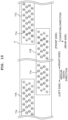
- FIG. 8 depicts an example where in the provisional setting step (S10), the first through fifth nozzles 11a from right in the medium width direction have been corresponded with the power supply circuit 24, the sixth through twentieth nozzles 11a from right in the medium width direction have been corresponded with the power supply circuit 23, and the twenty-first through thirty-second nozzles 11a from right in the medium width direction have been corresponded with the power supply circuit 22. Note that in FIG.
- the numeral 2 depicted inside a nozzle 11a indicates that said nozzle 11a is corresponded with the power supply circuit 22
- the numeral 3 depicted inside a nozzle 11a indicates that said nozzle 11a is corresponded with the power supply circuit 23
- the numeral 4 depicted inside a nozzle 11a indicates that said nozzle 11a is corresponded with the power supply circuit 24. In other words, it is depicted in FIG.
- the power supply circuit to be associated with each nozzle 11a is provisionally determined based on the measurement result by the densitometer. In other words, in the provisional setting step S10, correction of density is performed within the head 11.
- the test printing step S20 and density difference determining step S30 are further performed, and, if required, the setting adjusting step S40 is performed, subsequently to the temporary setting step S10. As a result, density differences occurring among the heads 11 are corrected.
- test printing step S20 for each line head 4, a test pattern is printed on the print medium M, in accordance with the correspondence of power supply circuits with each of the nozzles 11a that has been set in the provisional setting step S10.
- the print medium M is moved in the conveying direction with respect to the line heads 4.
- ink droplets are discharged from each of the plurality of nozzles 11a of all heads 11 included in one line head 4.
- the drive element 111 corresponding to each nozzle 11a is supplied with a voltage from the some one of the power supply circuits 22, 23, 24 that has been corresponded with said nozzle 11a, whereby a plurality of ink droplets is discharged from said nozzle 11a.
- the 10 heads 11 included in each line head 4 are disposed in a zig-zag manner along the medium width direction.
- right end portions of the five heads 11 disposed on the front side respectively overlap in the conveying direction left end portions of the five heads 11 disposed on the rear side.
- each line head 4 there exist nine regions where fellow end portions in the medium width direction of two heads 11 overlap in the conveying direction.
- eight of the nozzles 11a included in the head 11 on the front side respectively overlap in the conveying direction eight of the nozzles 11a included in the head 11 on the rear side.
- the test printing step S20 and the later-mentioned actual printing step S50 are configured so that in the region where fellow end portions in the medium width direction of two heads 11 overlap in the conveying direction, ink will not be discharged from four of the nozzles 11a positioned in the left end portion of one of the heads 11 and from four of the nozzles 11a positioned in the right end portion of the other of the heads 11.
- the four nozzles 11a positioned in the left end portion of one of the heads 11 and the four nozzles 11a positioned in the right end portion of the other of the heads 11 will be called non-discharging nozzles 11a, and in FIGS. 9A and 10 , the non-discharging nozzles 11a are depicted by broken lines.
- nozzles 11a other than the non-discharging nozzles 11a will sometimes be called discharging nozzles 11a.
- a nozzle in the present teaching means the discharging nozzle 11a.
- a plurality of ink droplets is caused to be discharged from all of the discharging nozzles 11a included in one line head 4, whereby, as depicted in FIG. 9B , a test pattern P having a rectangular shape long in the medium width direction is printed on the print medium M.
- dot columns Ar1-Ar5 extending in the conveying direction respectively indicate columns of dots formed by ink droplets that have been discharged from the hatched first through fifth nozzles 11a from right, among the discharging nozzles 11a of a head 11A depicted in FIG. 9A .
- FIG. 9B dot columns Ar1-Ar5 extending in the conveying direction respectively indicate columns of dots formed by ink droplets that have been discharged from the hatched first through fifth nozzles 11a from right, among the discharging nozzles 11a of a head 11A depicted in FIG. 9A .
- FIG. 9B dot columns Ar1-Ar5 extending in the conveying direction respectively indicate columns of dots
- dot columns Bl1-Bl5 extending in the conveying direction respectively indicate columns of dots formed by ink droplets that have been discharged from the hatched first through fifth nozzles 11a from left, among the discharging nozzles 11a of a head 11B depicted in FIG. 9A .
- dot columns Br1-Br5 extending in the conveying direction respectively indicate columns of dots formed by ink droplets that have been discharged from the hatched first through fifth nozzles 11a from right, among the discharging nozzles 11a of the head 11B depicted in FIG. 9A .
- FIG. 9B dot columns Bl1-Bl5 extending in the conveying direction respectively indicate columns of dots formed by ink droplets that have been discharged from the hatched first through fifth nozzles 11a from right, among the discharging nozzles 11a of the head 11B depicted in FIG. 9A .
- dot columns C11-C15 extending in the conveying direction respectively indicate columns of dots formed by ink droplets that have been discharged from the hatched first through fifth nozzles 11a from left, among the discharging nozzles 11a of a head 11C depicted in FIG. 9A .
- the first through fifth nozzles 11a from right, of the discharging nozzles 11a of the head 11A and first through fifth nozzles 11a from left, of the discharging nozzles 11a of the head 11B will undergo execution of the later-mentioned setting adjusting step (S40).
- a portion corresponding to the next join that is, a portion corresponding to a join of the head 11B and the head 11C (a region BR consisting of the dot columns Br1-Br5 and region CL consisting of the dot columns Cl1-Cl5 depicted in FIG. 9B ) undergoes execution of the density difference determining step (S30).
- the density difference determining step (S30) is executed on all of the joins included in the line head 4. Note that length in the medium width direction of the portion corresponding to each join (for example, the portion consisting of the region AR and the region BL in FIG.
- the setting adjusting step (S40) is executed so that the density difference ⁇ L* will be suppressed sufficiently for it to be visually unrecognizable by the naked eye.
- the discharging nozzles 11a corresponding to a region where the density difference ⁇ L* has been determined to be 0.5 or more in the density difference determining step S30 are associated with an unused power supply circuit.
- the drive voltages of the drive elements 111 corresponding to said discharging nozzles 11a are adjusted. Description will be made below in line with a specific example depicted in FIGS. 9A, 9B , and 10 . Note that in the description below, when “adjusting the drive voltage of a nozzle 11a" is mentioned, this means “adjusting the drive voltage of the drive element 111 corresponding to the nozzle 11a".
- each nozzle 11a included in the heads 11A-11C is corresponded with some one of the power supply circuits 22-24 in the provisional setting step (S10).
- the density difference ⁇ L* of the regions AR and BL has been determined to be 0.5 or more in the density difference determining step (S30).
- the drive voltages of the five nozzles 11a corresponding to the region AR (the hatched first through fifth nozzles 11a from right, among the discharging nozzles 11a of the head 11A) and the five nozzles 11a corresponding to the region BL (the hatched first through fifth nozzles 11a from left, among the discharging nozzles 11a of the head 11B) are adjusted.
- the five nozzles 11a corresponding to the region AR one is associated with the power supply circuit 24 whose output voltage is 19 V, and four are associated with the power supply circuits 23 whose output voltage is 18 V.
- drive voltages of the five nozzles 11a corresponding to the region AR and the five nozzles 11a corresponding to the region BL are adjusted so as to approach 18.6 V which is a median value of 18.2 V and 19 V. For example, as depicted in FIG.
- the output voltage of the unused power supply circuit 21 is changed from 16 V to 18.4 V, and the five nozzles 11a corresponding to the region AR are allocated with the power supply circuit 21 that has had its output voltage changed.
- the output voltage of the unused power supply circuit 21 is changed from 16 V to 18.8 V, and the five nozzles 11a corresponding to the region BL are allocated with the power supply circuit 21 that has had its output voltage changed.
- the numeral 1 depicted inside a nozzle 11a indicates that said nozzle 11a is associated with the power supply circuit 21.
- the average value of drive voltage of the five nozzles 11a corresponding to the region AR will be 18.4 V
- the average value of drive voltage of the five nozzles 11a corresponding to the region BL will be 18.8 V.
- a difference of the average value of drive voltage of the five nozzles 11a corresponding to the region AR and average value of drive voltage of the five nozzles 11a corresponding to the region BL will become smaller than before the drive voltages are adjusted.
- the density difference ⁇ L* of the region AR and the region BL can be made smaller than before the drive voltages are adjusted.
- the region AR can have its density set to a density included in a range from density of the region AR to density of the region BL prior to the setting adjusting step (S40) being performed.
- the region BL can have its density set to a density included in a range from density of the region AR to density of the region BL prior to the setting adjusting step (S40) being performed.
- the density difference ⁇ L* has been determined to be 0.5 or more.
- drive voltages of the five nozzles 11a corresponding to the region BR and the five nozzles 11a corresponding to the region CL are adjusted so as to approach 18.5 V which is a median value of 19 V and 18 V.
- the output voltage of the unused power supply circuit 25 is changed from 20 V to 18.7 V, and the five nozzles 11a corresponding to the region BR are allocated with the power supply circuit 25 that has had its output voltage changed.
- the output voltage of the unused power supply circuit 25 is changed from 20 V to 18.3 V, and the five nozzles 11a corresponding to the region CL are allocated with the power supply circuit 25 that has had its output voltage changed.
- the numeral 5 depicted inside a nozzle 11a indicates that said nozzle 11a is associated with the power supply circuit 25.
- the average value of drive voltage of the five nozzles 11a corresponding to the region BR will be 18.7 V
- the average value of drive voltage of the five nozzles 11a corresponding to the region CL will be 18.3 V.
- a difference of the average value of drive voltage of the five nozzles 11a corresponding to the region BR and average value of drive voltage of the five nozzles 11a corresponding to the region CL will become smaller than before the drive voltages are adjusted.
- the density difference ⁇ L* of the region BR and the region CL can be made smaller than before the drive voltages are adjusted.
- the region BR can have its density set to a density included in a range from density of the region BR to density of the region CL prior to the setting adjusting step (S40) being performed.
- the region CL can also have its density set to a density included in a range from density of the region BR to density of the region CL prior to the setting adjusting step (S40) being performed.
- the density difference determining step (S30) is executed on all of the joins included in one line head 4, and joins where the density difference ⁇ L * has been determined to be 0.5 or more undergo execution of the setting adjusting step (S40). Then, the correspondence relationship of the nozzles 11a and power supply circuits that has been changed in the setting adjusting step (S40) is stored in the nonvolatile memory 52. Then, after the above-described steps have been completed for all of the line heads 4, the actual printing step (S50) is executed. In the actual printing step (S50), a voltage is supplied to the drive element 111 corresponding to each nozzle 11a, in accordance with correspondence information of the power supply circuits stored in the nonvolatile memory 52. Then, ink droplets are discharged from each nozzle 11a, whereby printing is performed on the print medium M.
- the head 11A and head 11B are one example of "a first ink jet head and second ink jet head” of the present invention
- the head 11B and head 11C are another one example of "a first ink jet head and second ink jet head” of the present invention.
- the first through fifth nozzles 11a from right, of the discharging nozzles 11a of the head 11A are one example of "a plurality of first nozzles positioned in an end portion on one side in the first direction, of the plurality of nozzles that the first ink jet head includes" of the present invention
- the first through fifth nozzles 11a from left, of the discharging nozzles 11a of the head 11B are one example of "a plurality of second nozzles positioned in an end portion on the other side in the first direction, of the plurality of nozzles that the second ink jet head includes" of the present invention.
- first through fifth nozzles 11a from right, of the discharging nozzles 11a of the head 11B are one example of "a plurality of first nozzles positioned in an end portion on one side in the first direction, of the plurality of nozzles that the first ink jet head includes" of the present invention
- first through fifth nozzles 11a from left, of the discharging nozzles 11a of the head 11C are one example of "a plurality of second nozzles positioned in an end portion on the other side in the first direction, of the plurality of nozzles that the second ink jet head includes" of the present invention.
- the regions AR and BL in the test pattern P are one example of "a first image region” and “a second image region” of the present invention
- the regions BR and CL in the test pattern P are another one example of "a first image region” and "a second image region” of the present invention.
- the drive voltage 18.4 V of the five nozzles 11a corresponding to the region AR and drive voltage 18.8 V of the five nozzles 11a corresponding to the region BL, subsequent to the setting adjusting step (S40) are one example of "a first voltage” and "a second voltage” of the present invention.
- the drive voltage 18.7 V of the five nozzles 11a corresponding to the region BR and drive voltage 18.3 V of the five nozzles 11a corresponding to the region CL, subsequent to the setting adjusting step (S40) are another one example of "a first voltage” and "a second voltage” of the present invention.
- the above-described embodiment of the present invention results in that, after the drive voltage of each nozzle 11a has been adjusted in the provisional setting step (S10) so as to prevent density variation occurring within each head 11, solely a join of two heads 11 where the density difference ⁇ L* has been determined to be 0.5 or more in the density difference determining step (S30) undergoes execution of the setting adjusting step (S40). Therefore, the density difference ⁇ L* of the join of said two heads 11 can be more efficiently eased, compared to when the drive voltages of all of the discharging nozzles 11a included in the two heads 11 are adjusted. Moreover, overall lowering of discharge speeds of the ink droplets, generation of mist, and so on, of the kind that occur when drive voltages of all of the discharging nozzles 11a included in said two heads 11 are adjusted, can be suppressed.
- length in the medium width direction of the portion corresponding to each join of the test pattern P is 0.5 mm or more, and the setting adjusting step (S40) is executed only in the case of density difference ⁇ L* in such a portion being 0.5 or more.
- the setting adjusting step (S40) is executed only in the case of density difference ⁇ L* in such a portion being 0.5 or more.
- the density difference ⁇ L* of the region AR and region BL and density difference ⁇ L* of the region BR and region CL are both 0.5 or more.
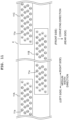
- the density difference ⁇ L* of the region AR and region BL may be eased by the drive voltages of the five nozzles 11a corresponding to the region AR alone being adjusted, as depicted in FIG. 11 , for example.
- the output voltage of the unused power supply circuit 21 may be changed to 18.6 V being the median value of 18.2 V and 19 V, and the five nozzles 11a corresponding to the region AR may be allocated with the power supply circuit 21 that has had its output voltage changed.
- the average value of drive voltage of the five nozzles 11a corresponding to the region AR will be 18.6 V, and the difference of the average value of drive voltage of the five nozzles 11a corresponding to the region AR and average value of drive voltage of the five nozzles 11a corresponding to the region BL will become smaller than before the drive voltages are adjusted.
- the density difference ⁇ L* of the region AR and region BL can be made smaller than before the drive voltages are adjusted.
- the region AR can have its density set to a density in-between density of the region AR and density of the region BL prior to the setting adjusting step (S40) being performed.
- the density difference ⁇ L* of the region BR and region CL may be eased by the drive voltages of the five nozzles 11a corresponding to the region BR alone being adjusted, as depicted in FIG. 11 , for example.
- the output voltage of the unused power supply circuit 21 may be changed to 18.5 V being the median value of 19 V and 18 V, and the five nozzles 11a corresponding to the region BR may be allocated with the power supply circuit 21 that has had its output voltage changed.
- the average value of drive voltage of the five nozzles 11a corresponding to the region BR will be 18.5 V, and the difference of the average value of drive voltage of the five nozzles 11a corresponding to the region BR and average value of drive voltage of the five nozzles 11a corresponding to the region CL will become smaller than before the drive voltages are adjusted.
- the density difference ⁇ L* of the region BR and region CL can be made smaller than before the drive voltages are adjusted.
- the region BR can have its density set to a density in-between density of the region BR and density of the region CL prior to the setting adjusting step (S40) being performed.
- each line head 4 of the above-described embodiment and above-described modified example there existed nine regions where fellow end portions in the medium width direction of two heads 11 overlapped in the conveying direction. Moreover, in the region where fellow end portions in the medium width direction of two heads 11 overlapped in the conveying direction, eight nozzles 11a included in the head 11 on the front side respectively overlapped in the conveying direction eight nozzles 11a included in the head 11 on the rear side.
- the number of nozzles 11a in a group of nozzles 11a overlapping in the conveying direction is not limited to eight, and may be seven or less, or may be nine or more.
- non-discharging nozzles 11a in the region where fellow end portions in the medium width direction of two heads 11 overlapped in the conveying direction, four nozzles 11a positioned in the left end portion of one of the heads 11 and four nozzles 11a positioned in the right end portion of the other of the heads 11 were configured as non-discharging nozzles 11a.
- the number of non-discharging nozzles 11a is not limited to four, and may be three or less, or may be five or more.
- n nozzles 11a (where n is a natural number) positioned in the left end portion of one of the heads 11 may be configured as non-discharging nozzles 11a, and n nozzles 11a positioned in the right end portion of the other of the heads 11 configured as discharging nozzles 11a.
- n nozzles 11a (where n is a natural number) positioned in the left end portion of one of the heads 11 may be configured as discharging nozzles 11a, and n nozzles 11a positioned in the right end portion of the other of the heads 11 configured as non-discharging nozzles 11a.
- length in the medium width direction of the portion corresponding to each join (for example, the portion consisting of the region AR and the region BL in FIG. 9B ), of the test pattern P was 0.5 mm or more, but is not limited to this, and may be 0.2 mm or more.
- the printing apparatus 1 in the above-described embodiment and above-described modified examples was configured so that the four line heads 4 fixed to the casing 2 had the print medium M conveyed under them in the conveying direction by the conveying rollers 5A, 5B.
- the printing apparatus 1 in the above-described embodiment and above-described modified examples is not limited to this, and may be configured so that the print medium M placed on the platen 3 has the line heads 4 moved over it in the conveying direction.
- the print medium M is not limited to paper, and may be a resin-made film or a fabric, for example.
Landscapes
- Engineering & Computer Science (AREA)
- Quality & Reliability (AREA)
- Ink Jet (AREA)
- Particle Formation And Scattering Control In Inkjet Printers (AREA)
Claims (9)
- Verfahren zum Korrigieren eines Bildes in einer Druckeinrichtung (1), die Zeilenköpfe beinhaltet, wobei das Verfahren umfasst:Bewegen eines ersten (11A) und zweiten (11B) Tintenstrahlkopfes und eines Mediums (m) relativ zueinander, wobei der erste (11A) und der zweite (11B) Tintenstrahlkopf entlang einer ersten Richtung angeordnet sind, wobei jeder des ersten (11A) und des zweiten (11B) Tintenstrahlkopfes Düsen (11a) und Antriebselemente (111) beinhaltet, die jeweils den Düsen (11a) entsprechen, wobei der erste (11A) und der zweite (11B) Tintenstrahlkopf und das Medium (m) relativ zueinander in einer zweiten Richtung bewegt werden, die sich mit der ersten Richtung schneidet;Ausstoßen von Tintentröpfchen aus den Düsen (11a) des ersten (11A) und des zweiten (11B) Tintenstrahlkopfes, indem jedes der Antriebselemente (111) mit einer der Stromversorgungsschaltungen (21-26), die aus den Stromversorgungsschaltungen (21-26) ausgewählt sind, verbunden wird und Spannung an jedes der Antriebselemente (111) zu einem vorbestimmten Zeitpunkt angelegt wird, während der erste (11A) und der zweite (11B) Tintenstrahlkopf und das Medium (m) in der zweiten Richtung bewegt werden, wobei die Stromversorgungsschaltungen (21-26) alle derart eingestellt sind, dass ihre Ausgangsspannungen unterschiedlich sind;Bestimmen einer Dichtedifferenz zwischen einem ersten Bildbereich (AR) und einem zweiten Bildbereich, wobei der Bildbereich (AR) auf dem Medium (m) durch die Tintentröpfchen ausgebildet wird, die von ersten Düsen ausgestoßen werden, wobei die ersten Düsen in den Düsen (11a) des ersten Tintenstrahlkopfes (11A) beinhaltet sind und in einem Endabschnitt auf einer Seite in der ersten Richtung unter den Düsen (11a) des ersten Tintenstrahlkopfes (11A) positioniert sind, wobei der zweite Bildbereich (BL) auf dem Medium (m) durch die aus den zweiten Düsen ausgestoßenen Tintentröpfchen ausgebildet wird, wobei die zweiten Düsen in den Düsen (11a) des zweiten Tintenstrahlkopfes (11B) beinhaltet sind und in einem Endabschnitt auf der anderen Seite in der ersten Richtung unter den Düsen (11a) des zweiten Tintenstrahlkopfes (11B) positioniert sind, wobei die Endabschnitte des ersten Tintenstrahlkopfes (11A) und des zweiten Tintenstrahlkopfes (11B) sich in der zweiten Richtung überlappen, und eine Anzahl von Düsen (11a), die in dem Endabschnitt des ersten Tintenstrahlkopfes (11A) positioniert sind, und eine Anzahl von Düsen (11a), die in dem Endabschnitt des zweiten Tintenstrahlkopfes positioniert sind, als Nicht-Ausstoßdüsen (11a) konfiguriert sind; undSchalten der an die ersten Antriebselemente anzulegenden Spannung auf eine erste Spannung durch Schalten der Stromversorgungsschaltungen (21-26), die mit den ersten Antriebselementen zu verbinden sind, auf Grundlage des Dichteunterschieds, wobei die ersten Antriebselemente in den Antriebselementen (111) des ersten Tintenstrahlkopfes (11A) beinhaltet sind und den ersten Düsen entsprechen, wobei die erste Spannung sich von der an die Antriebselemente, die nicht die ersten Antriebselemente sind, des ersten Tintenstrahlkopfes (11A) anzulegenden Spannung unterscheidet, wobei das Umschalten der an die ersten Antriebselemente anzulegenden Spannung durch Umschalten der Stromversorgungsschaltungen auf eine unbenutzte Stromversorgungsschaltung erreicht wird, deren Ausgangsspannung geändert wurde, sodass der Dichteunterschied verkleinert wird.
- Verfahren zum Korrigieren eines Bildes nach Anspruch 1, wobei in einem Fall des Anlegens der ersten Spannung an die ersten Antriebselemente die Dichte eines Bildbereichs, der auf dem Medium (m) durch die Tintentröpfchen ausgebildet wird, die aus den ersten Düsen ausgestoßen werden, in einem Dichtebereich von der Dichte des ersten Bildbereichs (AR) zu der Dichte eines zweiten Bildbereichs (BL) beinhaltet ist.
- Verfahren zum Korrigieren eines Bildes nach Anspruch 2, wobei in einem Fall des Anlegens der ersten Spannung an die ersten Antriebselemente die Dichte eines Bildbereichs, der auf dem Medium durch die Tintentröpfchen ausgebildet wird, die aus den ersten Düsen ausgestoßen werden, eine Zwischendichte zwischen der Dichte des ersten Bildbereichs (AL) und der Dichte eines zweiten Bildbereichs (BR) ist.
- Verfahren zum Korrigieren eines Bildes nach einem der Ansprüche 1 bis 3, wobei die Stromversorgungsschaltungen (21-26), die mit den ersten Antriebselementen zu verbinden sind, geschaltet werden, ohne die Stromversorgungsschaltungen (21-26), die mit den zweiten Antriebselementen zu verbinden sind, die den zweiten Düsen entsprechen, zu schalten.
- Verfahren zum Korrigieren eines Bildes nach einem der Ansprüche 1 bis 3, das ferner das Schalten der an die zweiten Antriebselemente anzulegenden Spannung auf eine zweite Spannung durch Schalten der Stromversorgungsschaltungen (21-26), die mit den zweiten Antriebselementen zu verbinden sind, auf Grundlage des Dichteunterschieds, wobei die zweiten Antriebselemente in den Antriebselementen (111) des zweiten Tintenstrahlkopfes (11B) beinhaltet sind und den zweiten Düsen entsprechen, wobei sich die zweite Spannung von der Spannung unterscheidet, die an andere Antriebselemente (111) des zweiten Tintenstrahlkopfes (11B) als die zweiten Antriebselemente anzulegen ist.
- Verfahren zum Korrigieren eines Bildes nach einem der Ansprüche 1 bis 5,wobei die Dichte des ersten Bildbereichs (AR) und die Dichte des zweiten Bildbereichs (BL) durch ein Densitometer gemessen werden, undder Dichteunterschied auf Grundlage eines gemessenen Ergebnisses bestimmt wird.
- Verfahren zum Korrigieren eines Bildes nach einem der Ansprüche 1 bis 6, wobei eine Länge in der ersten Richtung eines Bereichs, der aus dem ersten Bildbereich (AR) und dem zweiten Bildbereich (BL) besteht, 0,2 mm oder mehr beträgt.
- Verfahren zum Korrigieren eines Bildes nach einem der Ansprüche 1 bis 7, wobei in einem Fall, in dem der Dichteunterschied zwischen dem ersten Bildbereich (AR) und dem zweiten Bildbereich (BL) 0,5 L* oder mehr beträgt, die an die ersten Antriebselemente anzulegende Spannung auf die erste Spannung geschaltet wird.
- Druckeinrichtung (1), die Zeilenköpfe beinhaltet, die umfassen:Stromversorgungsschaltungen (21-26), die alle derart eingestellt sind, dass ihre Ausgangsspannungen unterschiedlich sind;einen ersten (11A) und einen zweiten (11B) Tintenstrahlkopf, entlang einer ersten Richtung angeordnet sind, wobei jeder des ersten (11A) und des zweiten (11B) Tintenstrahlkopfes Düsen (11a) und Antriebselemente (111) beinhaltet, die jeweils den Düsen (11a) entsprechen;einen Bewegungsmechanismus (5A, 5B), der dazu konfiguriert ist, den ersten (11A) und den zweiten (11B) Tintenstrahlkopf und ein Medium (m) relativ zueinander in einer zweiten Richtung zu bewegen, die sich mit der ersten Richtung schneidet; undeine Steuervorrichtung (7), die dazu konfiguriert ist, den ersten (11A) und zweiten (11B) Tintenstrahlkopf und den Bewegungsmechanismus (5A, 5B) zu steuern,jedes der Antriebselemente (111), die in dem ersten (11A) und dem zweiten (11B) Tintenstrahlkopf beinhaltet sind, mit einer der Stromversorgungsschaltungen (21-26) verbunden ist, die aus den Stromversorgungsschaltungen (21-26) ausgewählt ist,die Steuervorrichtung (7) dazu konfiguriert ist, Spannung an jedes der Antriebselemente (111), die in dem ersten (11A) und zweiten (11B) Tintenstrahlkopf beinhaltet sind, zu einem vorbestimmten Zeitpunkt anzulegen, während der erste (11A) und der zweite (11B) Tintenstrahlkopf und das Medium (m) in der zweiten Richtung relativ zueinander bewegt werden, sodass Tintentröpfchen aus den Düsen (11a), die in dem ersten (11A) und zweiten (11B) Tintenstrahlkopf beinhaltet sind, ausgestoßen werden,die Düsen (11a) des ersten Tintenstrahlkopfes (11A) erste Düsen beinhalten, die in einem Endabschnitt auf einer Seite in der ersten Richtung angeordnet sind,die Düsen (11a) des zweiten Tintenstrahlkopfes (11B) zweite Düsen beinhalten, die in einem Endabschnitt auf der anderen Seite in der ersten Richtung angeordnet sind,die Endabschnitte des ersten Tintenstrahlkopfes (11A) und des zweiten Tintenstrahlkopfes (11B) sich in der zweiten Richtung überlappen, und eine Anzahl von Düsen (11a), die in dem Endabschnitt des ersten Tintenstrahlkopfes (11A) positioniert sind, und eine Anzahl von Düsen (11a), die in dem Endabschnitt des zweiten Tintenstrahlkopfes (11B) positioniert sind, als Nicht-Ausstoßdüsen (11a) konfiguriert sind,ein erster Bildbereich (AR) auf dem Medium (m) durch die Tintentröpfchen ausgebildet wird, die aus den ersten Düsen ausgestoßen werden,ein zweiter Bildbereich (BL) auf dem Medium durch die Tintentröpfchen ausgebildet wird, die aus den zweiten Düsen ausgestoßen werden,die Antriebselemente (111) des ersten Tintenstrahlkopfes erste Antriebselemente beinhalten, die den ersten Düsen entsprechen, unddie Steuervorrichtung (7) dazu konfiguriert ist, die an die ersten Antriebselemente anzulegende Spannung auf eine erste Spannung zu schalten, indem die mit den ersten Antriebselementen zu verbindenden Stromversorgungsschaltungen (21-26) auf Grundlage eines Dichteunterschieds zwischen dem ersten Bildbereich (AR) und dem zweiten Bildbereich (BL) geschaltet werden, wobei sich die erste Spannung von der Spannung unterscheidet, die an andere Antriebselemente des ersten Tintenstrahlkopfes (11A) als die ersten Antriebselemente anzulegen ist,wobei die an die ersten Antriebselemente anzulegende Spannung auf eine erste Spannung umgeschaltet wird, indem die mit den ersten Antriebselementen zu verbindenden Stromversorgungsschaltungen (21-26) auf eine unbenutzte Stromversorgungsschaltung geschaltet wird, deren Ausgangsspannung verändert wurde, sodass der Dichteunterschied kleiner gemacht wird.
Applications Claiming Priority (1)
| Application Number | Priority Date | Filing Date | Title |
|---|---|---|---|
| JP2021153600A JP2023045287A (ja) | 2021-09-21 | 2021-09-21 | 画像補正方法及び印刷装置 |
Publications (2)
| Publication Number | Publication Date |
|---|---|
| EP4151420A1 EP4151420A1 (de) | 2023-03-22 |
| EP4151420B1 true EP4151420B1 (de) | 2025-06-18 |
Family
ID=82786848
Family Applications (1)
| Application Number | Title | Priority Date | Filing Date |
|---|---|---|---|
| EP22187830.9A Active EP4151420B1 (de) | 2021-09-21 | 2022-07-29 | Verfahren zur bildkorrektur und druckvorrichtung |
Country Status (3)
| Country | Link |
|---|---|
| US (1) | US11987062B2 (de) |
| EP (1) | EP4151420B1 (de) |
| JP (1) | JP2023045287A (de) |
Family Cites Families (21)
| Publication number | Priority date | Publication date | Assignee | Title |
|---|---|---|---|---|
| JP4298836B2 (ja) * | 1998-06-30 | 2009-07-22 | 東芝テック株式会社 | インクジェット記録装置 |
| JP4241195B2 (ja) * | 2003-06-02 | 2009-03-18 | ソニー株式会社 | 液体吐出装置の濃度調整方法、液体吐出装置の濃度調整システム、及び液体吐出装置 |
| JP2006137040A (ja) * | 2004-11-11 | 2006-06-01 | Toshiba Tec Corp | インクジェット記録装置 |
| JP2007030503A (ja) * | 2005-06-21 | 2007-02-08 | Olympus Corp | 画像形成装置及び画像形成方法 |
| JP2007261027A (ja) * | 2006-03-28 | 2007-10-11 | Olympus Corp | 画像記録装置の記録濃度調整方法及びプログラム |
| JP2007301952A (ja) * | 2006-05-15 | 2007-11-22 | Seiko Epson Corp | 画像処理装置、画像処理方法、印刷装置、印刷方法、画像処理プログラム、印刷プログラム、及び記録媒体 |
| JP2009051066A (ja) * | 2007-08-26 | 2009-03-12 | Sony Corp | 吐出条件調整装置、液滴吐出装置、吐出条件調整方法及びプログラム |
| JP5625332B2 (ja) * | 2009-01-16 | 2014-11-19 | 株式会社リコー | 画像形成方法、画像形成装置、及びプログラム |
| JP5293408B2 (ja) * | 2009-05-29 | 2013-09-18 | 株式会社リコー | 画像形成装置 |
| JP2011218565A (ja) * | 2010-04-02 | 2011-11-04 | Olympus Corp | 画像記録装置 |
| JP5653194B2 (ja) * | 2010-11-30 | 2015-01-14 | 理想科学工業株式会社 | インクジェット記録装置の濃度調整モジュール及びインクジェット記録装置の濃度調整方法 |
| JP5732905B2 (ja) * | 2011-02-28 | 2015-06-10 | セイコーエプソン株式会社 | 液体噴射装置 |
| JP5779929B2 (ja) * | 2011-03-24 | 2015-09-16 | セイコーエプソン株式会社 | 印刷装置、及び、印刷方法 |
| US8414102B2 (en) * | 2011-08-11 | 2013-04-09 | Xerox Corporation | In situ calibration of multiple printheads to reference ink targets |
| JP5775510B2 (ja) * | 2012-12-27 | 2015-09-09 | 富士フイルム株式会社 | ヘッドモジュールの調整方法、インクジェットヘッドの製造方法 |
| JP2016101745A (ja) * | 2014-11-28 | 2016-06-02 | キヤノン株式会社 | 画像処理装置、画像処理方法および画像記録装置 |
| JP6416432B1 (ja) * | 2018-06-26 | 2018-10-31 | 株式会社トライテック | インクジェット印刷装置におけるインク濃度誤差補正方法 |
| JP6897992B2 (ja) | 2018-10-30 | 2021-07-07 | 株式会社トライテック | インクジェット印刷装置における調整方法及びインクジェット印刷装置 |
| JP6541858B1 (ja) * | 2018-10-30 | 2019-07-10 | 株式会社トライテック | インクジェット印刷装置におけるインク濃度誤差補正方法 |
| JP7367405B2 (ja) * | 2019-09-04 | 2023-10-24 | ブラザー工業株式会社 | 印刷装置及び印刷方法 |
| JP2021104584A (ja) * | 2019-12-26 | 2021-07-26 | 理想科学工業株式会社 | 濃度補正プロファイル生成装置 |
-
2021
- 2021-09-21 JP JP2021153600A patent/JP2023045287A/ja active Pending
-
2022
- 2022-07-29 EP EP22187830.9A patent/EP4151420B1/de active Active
- 2022-08-10 US US17/818,832 patent/US11987062B2/en active Active
Also Published As
| Publication number | Publication date |
|---|---|
| EP4151420A1 (de) | 2023-03-22 |
| JP2023045287A (ja) | 2023-04-03 |
| US11987062B2 (en) | 2024-05-21 |
| US20230091544A1 (en) | 2023-03-23 |
Similar Documents
| Publication | Publication Date | Title |
|---|---|---|
| US9597893B2 (en) | Element substrate and liquid discharge head | |
| EP3381689B1 (de) | Flüssigkeitsstrahlvorrichtung | |
| US11420441B2 (en) | Printing apparatus and printing method | |
| CN101648458B (zh) | 液体喷出装置和液体喷出方法 | |
| JP2018043486A (ja) | 制御基板、印刷装置及びヘッドモジュール | |
| WO2019188329A1 (ja) | 液滴吐出装置 | |
| JP2019119171A (ja) | 液滴吐出装置 | |
| EP4151420A1 (de) | Verfahren zur bildkorrektur und druckvorrichtung | |
| US11203206B2 (en) | Image recording apparatus | |
| US11504964B2 (en) | Printing apparatus and printing method | |
| JP7484339B2 (ja) | 印刷装置 | |
| JP7499645B2 (ja) | 液体吐出ヘッド駆動回路 | |
| EP3825128B1 (de) | Druckvorrichtung | |
| EP4530075A1 (de) | Druckverfahren und druckvorrichtung | |
| JP5991069B2 (ja) | 液滴吐出装置および特性変化検査方法 | |
| US11685156B2 (en) | Liquid discharge head and printing apparatus provided with liquid discharge head | |
| JP2022151303A (ja) | インク滴の着弾位置の補正方法及び印刷装置 | |
| JP7499644B2 (ja) | 多出力駆動回路 | |
| JP2022085158A (ja) | ヘッドの吐出調整方法 | |
| JP7499643B2 (ja) | 液体吐出ヘッド駆動回路 | |
| JP2018171854A (ja) | 液体吐出装置及び液体吐出装置の電圧設定方法 | |
| JP2025094410A (ja) | 液体吐出ヘッドの駆動方法及び印刷装置 | |
| JP2006255977A (ja) | 液滴吐出ヘッドの駆動方法及び液滴吐出装置 |
Legal Events
| Date | Code | Title | Description |
|---|---|---|---|
| PUAI | Public reference made under article 153(3) epc to a published international application that has entered the european phase |
Free format text: ORIGINAL CODE: 0009012 |
|
| STAA | Information on the status of an ep patent application or granted ep patent |
Free format text: STATUS: THE APPLICATION HAS BEEN PUBLISHED |
|
| AK | Designated contracting states |
Kind code of ref document: A1 Designated state(s): AL AT BE BG CH CY CZ DE DK EE ES FI FR GB GR HR HU IE IS IT LI LT LU LV MC MK MT NL NO PL PT RO RS SE SI SK SM TR |
|
| P01 | Opt-out of the competence of the unified patent court (upc) registered |
Effective date: 20230425 |
|
| STAA | Information on the status of an ep patent application or granted ep patent |
Free format text: STATUS: REQUEST FOR EXAMINATION WAS MADE |
|
| 17P | Request for examination filed |
Effective date: 20230906 |
|
| RBV | Designated contracting states (corrected) |
Designated state(s): AL AT BE BG CH CY CZ DE DK EE ES FI FR GB GR HR HU IE IS IT LI LT LU LV MC MK MT NL NO PL PT RO RS SE SI SK SM TR |
|
| GRAP | Despatch of communication of intention to grant a patent |
Free format text: ORIGINAL CODE: EPIDOSNIGR1 |
|
| STAA | Information on the status of an ep patent application or granted ep patent |
Free format text: STATUS: GRANT OF PATENT IS INTENDED |
|
| INTG | Intention to grant announced |
Effective date: 20250226 |
|
| GRAS | Grant fee paid |
Free format text: ORIGINAL CODE: EPIDOSNIGR3 |
|
| GRAA | (expected) grant |
Free format text: ORIGINAL CODE: 0009210 |
|
| STAA | Information on the status of an ep patent application or granted ep patent |
Free format text: STATUS: THE PATENT HAS BEEN GRANTED |
|
| AK | Designated contracting states |
Kind code of ref document: B1 Designated state(s): AL AT BE BG CH CY CZ DE DK EE ES FI FR GB GR HR HU IE IS IT LI LT LU LV MC MK MT NL NO PL PT RO RS SE SI SK SM TR |
|
| REG | Reference to a national code |
Ref country code: GB Ref legal event code: FG4D |
|
| REG | Reference to a national code |
Ref country code: CH Ref legal event code: EP |
|
| REG | Reference to a national code |
Ref country code: DE Ref legal event code: R096 Ref document number: 602022016001 Country of ref document: DE |
|
| REG | Reference to a national code |
Ref country code: CH Ref legal event code: EP |
|
| REG | Reference to a national code |
Ref country code: IE Ref legal event code: FG4D |
|
| PG25 | Lapsed in a contracting state [announced via postgrant information from national office to epo] |
Ref country code: FI Free format text: LAPSE BECAUSE OF FAILURE TO SUBMIT A TRANSLATION OF THE DESCRIPTION OR TO PAY THE FEE WITHIN THE PRESCRIBED TIME-LIMIT Effective date: 20250618 |
|
| PGFP | Annual fee paid to national office [announced via postgrant information from national office to epo] |
Ref country code: DE Payment date: 20250708 Year of fee payment: 4 |
|
| REG | Reference to a national code |
Ref country code: LT Ref legal event code: MG9D |
|
| PG25 | Lapsed in a contracting state [announced via postgrant information from national office to epo] |
Ref country code: GR Free format text: LAPSE BECAUSE OF FAILURE TO SUBMIT A TRANSLATION OF THE DESCRIPTION OR TO PAY THE FEE WITHIN THE PRESCRIBED TIME-LIMIT Effective date: 20250919 Ref country code: NO Free format text: LAPSE BECAUSE OF FAILURE TO SUBMIT A TRANSLATION OF THE DESCRIPTION OR TO PAY THE FEE WITHIN THE PRESCRIBED TIME-LIMIT Effective date: 20250918 |
|
| PG25 | Lapsed in a contracting state [announced via postgrant information from national office to epo] |
Ref country code: BG Free format text: LAPSE BECAUSE OF FAILURE TO SUBMIT A TRANSLATION OF THE DESCRIPTION OR TO PAY THE FEE WITHIN THE PRESCRIBED TIME-LIMIT Effective date: 20250618 |
|
| PG25 | Lapsed in a contracting state [announced via postgrant information from national office to epo] |
Ref country code: HR Free format text: LAPSE BECAUSE OF FAILURE TO SUBMIT A TRANSLATION OF THE DESCRIPTION OR TO PAY THE FEE WITHIN THE PRESCRIBED TIME-LIMIT Effective date: 20250618 |
|
| PGFP | Annual fee paid to national office [announced via postgrant information from national office to epo] |
Ref country code: FR Payment date: 20250708 Year of fee payment: 4 Ref country code: AT Payment date: 20251020 Year of fee payment: 4 |
|
| PG25 | Lapsed in a contracting state [announced via postgrant information from national office to epo] |
Ref country code: RS Free format text: LAPSE BECAUSE OF FAILURE TO SUBMIT A TRANSLATION OF THE DESCRIPTION OR TO PAY THE FEE WITHIN THE PRESCRIBED TIME-LIMIT Effective date: 20250918 |
|
| REG | Reference to a national code |
Ref country code: NL Ref legal event code: MP Effective date: 20250618 |
|
| PG25 | Lapsed in a contracting state [announced via postgrant information from national office to epo] |
Ref country code: LV Free format text: LAPSE BECAUSE OF FAILURE TO SUBMIT A TRANSLATION OF THE DESCRIPTION OR TO PAY THE FEE WITHIN THE PRESCRIBED TIME-LIMIT Effective date: 20250618 |
|
| PG25 | Lapsed in a contracting state [announced via postgrant information from national office to epo] |
Ref country code: NL Free format text: LAPSE BECAUSE OF FAILURE TO SUBMIT A TRANSLATION OF THE DESCRIPTION OR TO PAY THE FEE WITHIN THE PRESCRIBED TIME-LIMIT Effective date: 20250618 |
|
| PG25 | Lapsed in a contracting state [announced via postgrant information from national office to epo] |
Ref country code: PT Free format text: LAPSE BECAUSE OF FAILURE TO SUBMIT A TRANSLATION OF THE DESCRIPTION OR TO PAY THE FEE WITHIN THE PRESCRIBED TIME-LIMIT Effective date: 20251020 |
|
| REG | Reference to a national code |
Ref country code: AT Ref legal event code: MK05 Ref document number: 1803876 Country of ref document: AT Kind code of ref document: T Effective date: 20250618 |
|
| PG25 | Lapsed in a contracting state [announced via postgrant information from national office to epo] |
Ref country code: IS Free format text: LAPSE BECAUSE OF FAILURE TO SUBMIT A TRANSLATION OF THE DESCRIPTION OR TO PAY THE FEE WITHIN THE PRESCRIBED TIME-LIMIT Effective date: 20251018 |
|
| PG25 | Lapsed in a contracting state [announced via postgrant information from national office to epo] |
Ref country code: AT Free format text: LAPSE BECAUSE OF FAILURE TO SUBMIT A TRANSLATION OF THE DESCRIPTION OR TO PAY THE FEE WITHIN THE PRESCRIBED TIME-LIMIT Effective date: 20250618 Ref country code: SM Free format text: LAPSE BECAUSE OF FAILURE TO SUBMIT A TRANSLATION OF THE DESCRIPTION OR TO PAY THE FEE WITHIN THE PRESCRIBED TIME-LIMIT Effective date: 20250618 |
|
| PG25 | Lapsed in a contracting state [announced via postgrant information from national office to epo] |
Ref country code: CZ Free format text: LAPSE BECAUSE OF FAILURE TO SUBMIT A TRANSLATION OF THE DESCRIPTION OR TO PAY THE FEE WITHIN THE PRESCRIBED TIME-LIMIT Effective date: 20250618 |
|
| PG25 | Lapsed in a contracting state [announced via postgrant information from national office to epo] |
Ref country code: PL Free format text: LAPSE BECAUSE OF FAILURE TO SUBMIT A TRANSLATION OF THE DESCRIPTION OR TO PAY THE FEE WITHIN THE PRESCRIBED TIME-LIMIT Effective date: 20250618 |
|
| PG25 | Lapsed in a contracting state [announced via postgrant information from national office to epo] |
Ref country code: EE Free format text: LAPSE BECAUSE OF FAILURE TO SUBMIT A TRANSLATION OF THE DESCRIPTION OR TO PAY THE FEE WITHIN THE PRESCRIBED TIME-LIMIT Effective date: 20250618 |
|
| PG25 | Lapsed in a contracting state [announced via postgrant information from national office to epo] |
Ref country code: SK Free format text: LAPSE BECAUSE OF FAILURE TO SUBMIT A TRANSLATION OF THE DESCRIPTION OR TO PAY THE FEE WITHIN THE PRESCRIBED TIME-LIMIT Effective date: 20250618 |
|
| PG25 | Lapsed in a contracting state [announced via postgrant information from national office to epo] |
Ref country code: ES Free format text: LAPSE BECAUSE OF FAILURE TO SUBMIT A TRANSLATION OF THE DESCRIPTION OR TO PAY THE FEE WITHIN THE PRESCRIBED TIME-LIMIT Effective date: 20250618 |
|
| REG | Reference to a national code |
Ref country code: CH Ref legal event code: H13 Free format text: ST27 STATUS EVENT CODE: U-0-0-H10-H13 (AS PROVIDED BY THE NATIONAL OFFICE) Effective date: 20260224 |
|
| PG25 | Lapsed in a contracting state [announced via postgrant information from national office to epo] |
Ref country code: LU Free format text: LAPSE BECAUSE OF NON-PAYMENT OF DUE FEES Effective date: 20250729 Ref country code: RO Free format text: LAPSE BECAUSE OF FAILURE TO SUBMIT A TRANSLATION OF THE DESCRIPTION OR TO PAY THE FEE WITHIN THE PRESCRIBED TIME-LIMIT Effective date: 20250618 |
|
| REG | Reference to a national code |
Ref country code: DE Ref legal event code: R097 Ref document number: 602022016001 Country of ref document: DE |
|
| REG | Reference to a national code |
Ref country code: BE Ref legal event code: MM Effective date: 20250731 |
|
| PG25 | Lapsed in a contracting state [announced via postgrant information from national office to epo] |
Ref country code: MC Free format text: LAPSE BECAUSE OF FAILURE TO SUBMIT A TRANSLATION OF THE DESCRIPTION OR TO PAY THE FEE WITHIN THE PRESCRIBED TIME-LIMIT Effective date: 20250618 |
|
| PG25 | Lapsed in a contracting state [announced via postgrant information from national office to epo] |
Ref country code: DK Free format text: LAPSE BECAUSE OF FAILURE TO SUBMIT A TRANSLATION OF THE DESCRIPTION OR TO PAY THE FEE WITHIN THE PRESCRIBED TIME-LIMIT Effective date: 20250618 |
|
| PG25 | Lapsed in a contracting state [announced via postgrant information from national office to epo] |
Ref country code: BE Free format text: LAPSE BECAUSE OF NON-PAYMENT OF DUE FEES Effective date: 20250731 Ref country code: IT Free format text: LAPSE BECAUSE OF FAILURE TO SUBMIT A TRANSLATION OF THE DESCRIPTION OR TO PAY THE FEE WITHIN THE PRESCRIBED TIME-LIMIT Effective date: 20250618 |
|
| PG25 | Lapsed in a contracting state [announced via postgrant information from national office to epo] |
Ref country code: CH Free format text: LAPSE BECAUSE OF NON-PAYMENT OF DUE FEES Effective date: 20250731 |
|
| PLBE | No opposition filed within time limit |
Free format text: ORIGINAL CODE: 0009261 |
|
| STAA | Information on the status of an ep patent application or granted ep patent |
Free format text: STATUS: NO OPPOSITION FILED WITHIN TIME LIMIT |
|
| REG | Reference to a national code |
Ref country code: CH Ref legal event code: L10 Free format text: ST27 STATUS EVENT CODE: U-0-0-L10-L00 (AS PROVIDED BY THE NATIONAL OFFICE) Effective date: 20260430 |