EP4139539B1 - Terrassenüberdachung - Google Patents
Terrassenüberdachung Download PDFInfo
- Publication number
- EP4139539B1 EP4139539B1 EP21727219.4A EP21727219A EP4139539B1 EP 4139539 B1 EP4139539 B1 EP 4139539B1 EP 21727219 A EP21727219 A EP 21727219A EP 4139539 B1 EP4139539 B1 EP 4139539B1
- Authority
- EP
- European Patent Office
- Prior art keywords
- wall
- connection means
- profile
- terrace
- canopy
- Prior art date
- Legal status (The legal status is an assumption and is not a legal conclusion. Google has not performed a legal analysis and makes no representation as to the accuracy of the status listed.)
- Active
Links
Images


Classifications
-
- E—FIXED CONSTRUCTIONS
- E04—BUILDING
- E04D—ROOF COVERINGS; SKY-LIGHTS; GUTTERS; ROOF-WORKING TOOLS
- E04D13/00—Special arrangements or devices in connection with roof coverings; Protection against birds; Roof drainage ; Sky-lights
- E04D13/04—Roof drainage; Drainage fittings in flat roofs, balconies or the like
- E04D13/064—Gutters
-
- E—FIXED CONSTRUCTIONS
- E04—BUILDING
- E04C—STRUCTURAL ELEMENTS; BUILDING MATERIALS
- E04C3/00—Structural elongated elements designed for load-supporting
- E04C3/02—Joists; Girders, trusses, or trusslike structures, e.g. prefabricated; Lintels; Transoms; Braces
- E04C3/04—Joists; Girders, trusses, or trusslike structures, e.g. prefabricated; Lintels; Transoms; Braces of metal
- E04C3/06—Joists; Girders, trusses, or trusslike structures, e.g. prefabricated; Lintels; Transoms; Braces of metal with substantially solid, i.e. unapertured, web
- E04C3/07—Joists; Girders, trusses, or trusslike structures, e.g. prefabricated; Lintels; Transoms; Braces of metal with substantially solid, i.e. unapertured, web at least partly of bent or otherwise deformed strip- or sheet-like material
-
- E—FIXED CONSTRUCTIONS
- E04—BUILDING
- E04D—ROOF COVERINGS; SKY-LIGHTS; GUTTERS; ROOF-WORKING TOOLS
- E04D13/00—Special arrangements or devices in connection with roof coverings; Protection against birds; Roof drainage ; Sky-lights
- E04D13/04—Roof drainage; Drainage fittings in flat roofs, balconies or the like
- E04D13/08—Down pipes; Special clamping means therefor
-
- E—FIXED CONSTRUCTIONS
- E04—BUILDING
- E04F—FINISHING WORK ON BUILDINGS, e.g. STAIRS, FLOORS
- E04F10/00—Sunshades, e.g. Florentine blinds or jalousies; Outside screens; Awnings or baldachins
-
- E—FIXED CONSTRUCTIONS
- E04—BUILDING
- E04H—BUILDINGS OR LIKE STRUCTURES FOR PARTICULAR PURPOSES; SWIMMING OR SPLASH BATHS OR POOLS; MASTS; FENCING; TENTS OR CANOPIES, IN GENERAL
- E04H6/00—Buildings for parking cars, rolling-stock, aircraft, vessels or like vehicles, e.g. garages
- E04H6/02—Small garages, e.g. for one or two cars
- E04H6/025—Small garages, e.g. for one or two cars in the form of an overhead canopy, e.g. carports
-
- E—FIXED CONSTRUCTIONS
- E04—BUILDING
- E04C—STRUCTURAL ELEMENTS; BUILDING MATERIALS
- E04C3/00—Structural elongated elements designed for load-supporting
- E04C3/02—Joists; Girders, trusses, or trusslike structures, e.g. prefabricated; Lintels; Transoms; Braces
- E04C3/04—Joists; Girders, trusses, or trusslike structures, e.g. prefabricated; Lintels; Transoms; Braces of metal
- E04C2003/0404—Joists; Girders, trusses, or trusslike structures, e.g. prefabricated; Lintels; Transoms; Braces of metal beams, girders, or joists characterised by cross-sectional aspects
- E04C2003/0408—Joists; Girders, trusses, or trusslike structures, e.g. prefabricated; Lintels; Transoms; Braces of metal beams, girders, or joists characterised by cross-sectional aspects characterised by assembly or the cross-section
- E04C2003/0413—Joists; Girders, trusses, or trusslike structures, e.g. prefabricated; Lintels; Transoms; Braces of metal beams, girders, or joists characterised by cross-sectional aspects characterised by assembly or the cross-section being built up from several parts
-
- E—FIXED CONSTRUCTIONS
- E04—BUILDING
- E04C—STRUCTURAL ELEMENTS; BUILDING MATERIALS
- E04C3/00—Structural elongated elements designed for load-supporting
- E04C3/02—Joists; Girders, trusses, or trusslike structures, e.g. prefabricated; Lintels; Transoms; Braces
- E04C3/04—Joists; Girders, trusses, or trusslike structures, e.g. prefabricated; Lintels; Transoms; Braces of metal
- E04C2003/0404—Joists; Girders, trusses, or trusslike structures, e.g. prefabricated; Lintels; Transoms; Braces of metal beams, girders, or joists characterised by cross-sectional aspects
- E04C2003/0426—Joists; Girders, trusses, or trusslike structures, e.g. prefabricated; Lintels; Transoms; Braces of metal beams, girders, or joists characterised by cross-sectional aspects characterised by material distribution in cross section
- E04C2003/0439—Joists; Girders, trusses, or trusslike structures, e.g. prefabricated; Lintels; Transoms; Braces of metal beams, girders, or joists characterised by cross-sectional aspects characterised by material distribution in cross section the cross-section comprising open parts and hollow parts
-
- E—FIXED CONSTRUCTIONS
- E04—BUILDING
- E04C—STRUCTURAL ELEMENTS; BUILDING MATERIALS
- E04C3/00—Structural elongated elements designed for load-supporting
- E04C3/02—Joists; Girders, trusses, or trusslike structures, e.g. prefabricated; Lintels; Transoms; Braces
- E04C3/04—Joists; Girders, trusses, or trusslike structures, e.g. prefabricated; Lintels; Transoms; Braces of metal
- E04C2003/0404—Joists; Girders, trusses, or trusslike structures, e.g. prefabricated; Lintels; Transoms; Braces of metal beams, girders, or joists characterised by cross-sectional aspects
- E04C2003/0443—Joists; Girders, trusses, or trusslike structures, e.g. prefabricated; Lintels; Transoms; Braces of metal beams, girders, or joists characterised by cross-sectional aspects characterised by substantial shape of the cross-section
- E04C2003/0465—Joists; Girders, trusses, or trusslike structures, e.g. prefabricated; Lintels; Transoms; Braces of metal beams, girders, or joists characterised by cross-sectional aspects characterised by substantial shape of the cross-section square- or rectangular-shaped
-
- E—FIXED CONSTRUCTIONS
- E04—BUILDING
- E04D—ROOF COVERINGS; SKY-LIGHTS; GUTTERS; ROOF-WORKING TOOLS
- E04D13/00—Special arrangements or devices in connection with roof coverings; Protection against birds; Roof drainage ; Sky-lights
- E04D13/04—Roof drainage; Drainage fittings in flat roofs, balconies or the like
- E04D13/08—Down pipes; Special clamping means therefor
- E04D2013/0893—Down pipes; Special clamping means therefor incorporated in building structure
-
- E—FIXED CONSTRUCTIONS
- E04—BUILDING
- E04F—FINISHING WORK ON BUILDINGS, e.g. STAIRS, FLOORS
- E04F13/00—Coverings or linings, e.g. for walls or ceilings
- E04F13/07—Coverings or linings, e.g. for walls or ceilings composed of covering or lining elements; Sub-structures therefor; Fastening means therefor
- E04F13/072—Coverings or linings, e.g. for walls or ceilings composed of covering or lining elements; Sub-structures therefor; Fastening means therefor composed of specially adapted, structured or shaped covering or lining elements
- E04F13/073—Coverings or linings, e.g. for walls or ceilings composed of covering or lining elements; Sub-structures therefor; Fastening means therefor composed of specially adapted, structured or shaped covering or lining elements for particular building parts, e.g. corners or columns
- E04F13/0736—Coverings or linings, e.g. for walls or ceilings composed of covering or lining elements; Sub-structures therefor; Fastening means therefor composed of specially adapted, structured or shaped covering or lining elements for particular building parts, e.g. corners or columns for columns
Definitions
- the present invention relates to a terrace canopy.
- Terrace canopies are usually set up to screen off or clear an outdoor area. For instance, such screen devices are often set up near houses, restaurants, shops, etc. to screen off an outdoor terrace or the like from sunlight, precipitation and/or wind, or conversely, to temporarily allow in sunlight.
- These terrace canopies can be implemented, for example, in the form of awnings, pergolas, verandas, carports, a pavilion, etc.
- Such a terrace canopy typically comprises a roof frame that is at least partially supported by columns. Exceptionally, the roof frame may also be supported by another roof construction.
- the roof frame is generally constructed of several beams that are composed into one or more frames into which a roof infill can be attached. The beams themselves are often a composition of a plurality of individual profiles.
- Such a roof frame is typically supported by four (or more) columns between which a wall infill may be provided. Likewise, less columns may be used in case the roof frame is supported by other structures, such as a wall of an already existing structure.
- the roof infill may be stationary or movable, for example, a retractable roof.
- the roof infill of a retractable roof may, for instance, consist of a rollable cloth or screen, slats that rotate around their axis, or of segments that can slide over each other.
- the segments may be panels that are partly made of (laminated) glass or plastic, such as PC or PMMA.
- the wall infill can also be stationary or movable. Examples are a rollable cloth or screen or movable, i.e. slidable or foldable, panels.
- a known problem with such terrace canopies is the amount of customization and/or the number of standard components that may be required to provide sufficient variation in the construction possibilities of the terrace canopy.
- BE 2014/0015 and WO 2015/104675 A1 disclose a terrace canopy which aims to at least partially solve the aforementioned problem.
- BE 2014/0015 discloses a beam for a terrace canopy, which beam is provided with an internal cavity for the purpose of draining precipitation incident on the terrace canopy, to a front end of the beam. Above the cavity, a space is provided in which a screen roll can be arranged which can be downwardly unrolled, the screen then being located between the cavity and the outer side (formed by the front cover of the beam).
- the total size of the beam increases, which is undesirable, among others, for reasons such as possible changes in the headroom, wind load and aesthetic appearance.
- a seam can be seen between the beam and the wall profile, which is visually undesirable.
- a terrace canopy comprising a beam, the beam having a top side, a bottom side, an inner side and an outer side, and comprising a base part that, in its cross-section, is provided with: a screen cavity configured to hold a screen roller, which screen cavity is delimited by an upright inner side wall and a horizontal top wall extending from the upright inner side wall in the direction of the outer side of the beam ; an upright outer side wall extending from the end of the horizontal top wall and provided at the top with a first upper connection means ; and an internal space above the screen cavity, wherein the upright outer side wall, on its outwardly facing side, is provided with a first connection means and in that the beam is further provided with: a wall profile and a second closure profile, wherein the wall profile is located on the outer side of the upright outer side wall and is configured to guide and/or hold a wall panel and is provided with a first complementary connection means, a second complementary connection means and a first upper connection means, the wall profile being connected to the base
- Said wall profile and said second closure profile can be removed and said second closure profile can be replaced by a first closure profile and vice versa, wherein said first closure profile can close off the internal space and is provided with a first complementary connection means, the first closure profile being able to be connected to the base part by connecting its first complementary connection means to the first upper connection means.
- connection means By providing the necessary connection means on the base profile, it is possible to obtain functionally different beams. On the one hand, it is possible not to provide a wall profile and to close the beam at its top with a first closure profile. On the other hand, a wall profile can be provided on the outer side of the screen cavity and the top side of the beam (incl. the wall profile) is then closed off with a second closure profile. Such additional functionality on the outer side of the beam allows, i.a., to obtain a double wall infill. In addition, this extra functionality is obtained by using the same connection means for multiple applications, avoiding the need for additional connection means.
- the upright inner side wall is provided at the top with a second upper connection means, the first closure profile and the second closure profile each being provided with a second complementary connection means, wherein the first closure profile is connected to the base part by means of connecting its second complementary connection means to the second upper connection means and wherein the second closure profile is connected to the base member by connecting its second complementary connection means to the second upper connection means.
- the second upper connection means comprises a female pin connection means and the second complementary connection means comprises a male pin connection means.
- the first upper connection means comprises a female pin connection means and the first complementary connection means of each closure profile includes a male pin connection means.
- first upper connection means and the first connection means each comprise a hook element and the first complementary connection means and said second complementary connection means of the wall profile comprise a hook member.
- connection means are simple to use and can also be provided during an extrusion process such that they can be manufactured integrally with (the base part of) the beam.
- the first upper connection means comprises a female pin connection means and a hook element. In this way, different connection methods are combined in one connection means such that the beam can be embodied more compact.
- the internal space is delimited by the horizontal top wall, the upright outer side wall and the upright inner side wall.
- This internal space can be used, for example, as a technical space for the placement of motors and/or motor controls for the drive of a slatted roof and/or the guiding of electrical cables.
- the outwardly facing surface of the second closure profile and the outwardly facing surface of the outer side wall of the wall profile lie substantially in the same plane.
- the outer side of the beam forms substantially a single plane, which is aesthetically desirable.
- the beam comprises a gutter part located below the base section and configured to drain precipitation incident on the terrace canopy to a front end of the beam.
- the base part and the gutter part are formed as separate profiles, wherein the upright inner side wall of the base profile at the bottom is provided with at least one, preferably at least two, connection means and in that the gutter profile is provided with at least one, preferably at least two corresponding connection means for connecting the base profile to the gutter profile.
- the gutter part provides the desired water drainage of the terrace canopy.
- connection means which, preferably, comprises a plurality of connection means.
- the base portion of the beam is provided with a first attachment means near the end of the horizontal wall and a second attachment means near an end of an upright wall extending from the location of the first attachment means such that there is a certain moderate distance between the attachment means.
- connection means near the end of the horizontal wall, as opposed to only one connection means in the beam of BE 2014/0015 .
- the two connection means allow to connect several functionally different profiles with the end of the horizontal wall without having to provide a connection at another location of the base part, as is the case in BE 2014 / 0015. Therefore, there is less loss of space in the base part.
- the wall profile comprises a rail configured for guiding at least one wall portion.
- each reference to an orientation of the beams will be interpreted with reference to the position when mounted in the terrace canopy. In this way there are four orientations, namely above, below, outer side and inner side.
- “above” refers to the part of the beam that is or will be oriented towards the top surface (the sky, e.g. the open sky)
- “below” refers to the part of the beam that is or will be oriented towards the ground plane (the soil, e.g. the terrace floor)
- substantially includes variations of +/- 10% or less, preferably +/- 5% or less, more preferably +/- 1% or less, and more preferably +/-0.1% or less, of the specified state, insofar as the variations are applicable to function in the disclosed invention. It is to be understood that the term “substantially A” is intended to also include “A”.
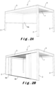
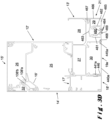
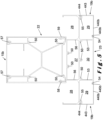
- FIG. 1 illustrates a terrace canopy 1 for a ground surface, for example a terrace or garden.
- the terrace canopy comprises a plurality of columns 2 that support different beams 3, 4, 5.
- the columns and beams together form frames to which wall infills 6 and/or roof coverings 7 can be attached as described hereafter.
- the terrace canopy 1 comprises three types of beams 3, 4, 5, namely:
- the beams 3, 4, 5 may be attached to other structures, for example a wall or facade, instead of resting solely on columns 2 as shown in Figure 1 .
- the terrace canopy 1 can generally be used to shield an outdoor space, as well as an indoor space.
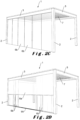
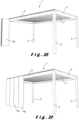
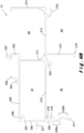
- FIGS 2A to 2J show terrace canopies 1 with alternative wall infills 6.
- the terrace canopies 1 shown have in common that four support columns 2 are provided which support a frame, also called a roof frame.
- the frame is formed from two external pivot beams 3 and two tension beams 5 in between a roof covering 7 is provided.
- the roof covering 7 is formed by slats which are rotatably attached at their front ends to pivot beams 3.
- the slats are rotatable between an open position and a closed position.
- In the open position there is an intermediate space between the slats through which, for example, air can be introduced into the underlying space or can leave this underlying space.
- In the closed position the slats form a closed roof with which the underlying space can be shielded from, for example, wind and/or precipitation, such as rain, hail or snow.
- the slats are typically arranged sloping towards one of both pivot beams 3.
- the slats are typically manufactured of a rigid material.
- This can be aluminium, for example. Aluminium has many advantages as a material, as it is at the same time robust and light-weighted, it can withstand bad weather conditions and requires little maintenance.
- other materials are also suitable and their advantages or disadvantages are assumed to be known by the skilled person.
- a slat can be produced using various techniques depending on the material, including extrusion, cutting, setting, casting, welding, etc. The appropriate production technique is assumed to be known by the skilled person.
- the slats are manufactured by means of an extrusion process.
- filling elements of, for example, polycarbonate, glass, wood, etc. can be used to fill the hollow slats at least partially, for instance to obtain a different appearance of the slat.
- the slats in their open position, may optionally be provided slidable in the terrace canopy 1, in order to further increase the control options in terms of incidence of light, radiant heat and ventilation.
- the roof covering 7 is stationary or movable.
- a movable roof covering comprises, for example, tiltable and/or slidable slats (such as described above) and/or roll-in/roll-out screens and/or slidable panels.
- the individual elements of the movable roof covering 7 in their closed position form a substantially watertight roof with which the underlying space can be screened off from, for instance, wind and/or precipitation, such as rain, hail or snow.
- This roof covering 7 is typically drained to the pivot beams 3, 4 and from there directly or via the tension beams 5 to the columns 2.
- the roof covering 7 can be at least partially opened and/or closed in order to be able to determine the incidence of light, radiant heat, ventilation, precipitation, etc. to the space below the roof covering 7 as desired.
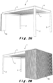
- FIG. 2D A combination of the wall infills of Figures 2A to 2C is shown in Figure 2D .
- a double wall infill is provided, which, on the one hand, comprises a roll-in/roll-out screen 6a and, on the other hand, slidable wall panels 6b (in this case four panels 6b on either side).
- connection for each interconnection of two profiles, use is made of two separate connections. This improves the strength of the connection, but mainly contributes to the correct mutual positioning of the profiles. The fact is that if only one connection is used for two profiles, there is more clearance in the mutual positioning, which can give rise to a divergent positioning, in particular due to wind loads and/or precipitation loads.
- Figure 5A further illustrates that the upright wall 100 of the base profile 12 is provided on its top side with a bend 106, through which a first upper connection means 102, in particular a female pin connection means, is provided further to the outer side of the base profile 12.
- the first upper connection means 102 is used to connect the cover profile 15.
- the cover profile 15 comprises a horizontal wall 400 which merges at its ends into two upright walls 401, 402 and is therefore substantially U-shaped, which is advantageous for avoiding or at least reducing infiltrating water.
- the bottom side of the horizontal wall 400 is provided with two connection means 403, 404, in particular pins.
- the pin 403 is used together with the first upper connection means 102 for connecting the cover profile 15 to the base profile 12. Due to the bend 106, the upright wall 100 of the base profile 12 and the upright wall 401 of the cover profile 15 are in the same plane.
- connection profile 16 comprises a hollow chamber formed between four walls 411, 412, 413, 414.
- the wall 414 forms the top side of the connection profile 16 and is provided with a first connection means 35, in particular a hooking means formed by two hooks, corresponding to the first connection means 108.
- a branch 415 extends towards the inner side of the external pivot beam 3. The end of branch 415 engages in a notch 110 in the base profile 12.
- the connection profile 16 is provided with a second connection means 416, in particular a female pin connection means.
- the second connection means 416 serves for receiving a corresponding second connection means 36, in particular a pin.
- This second connection means 36 is provided on the inner side of the front cover 14.
- a further attachment of the front cover 14 to the base profile 12 is formed, in particular by a pivotal movement, by placing the end part 37 of the front cover 14 in a slot 109 in the base profile 12 intended for this purpose.
- the support profile 17 comprises a horizontal wall 420 terminating in a first connection means 421, in particular a female pin connection means.
- a corresponding connection means 39 is provided on the inner side of the front cover 14.
- an upright wall 422 and a branch 423 are provided at the other end of the horizontal wall 420.
- the upright wall 422 serves as an abutment against the internal cavity 27 of the double gutter profile 13, i.e. against the outer upright wall 206.
- the end of the upright wall 422 engages in a notch 207 in the double gutter profile 13, in particular a notch 207 in the outer side wall 206 of the cavity 27.
- the end of the branch 423 engages in an opening 208 near the corner of the internal cavity 27.
- the filler profile 18 is generally U-shaped with a flat bottom side 430 and upright side walls 431, 432.
- the upright side wall 432 in particular the end thereof, is intended to be fixedly connected to wall part 209a of an outer upright branch 209 of the double gutter profile 13. In an example, rivets are used for this connection.
- the remaining upright side wall 431 is free and serves as an abutment for the bottom side of the front cover 14. If desired, the upright side wall 431 can also be fixedly attached to the front cover 14.
- the upright side wall 432 is provided with a connection means 433, in particular a pin, the function of which will be described later.
- the front cover 14 is further provided with a reinforcing rib 41 and a slot 42.
- the reinforcing rib 41 contributes to the rigidity of the front cover 14 and is useful for obtaining the required resistance at higher loads, especially when bridging relatively long lengths.
- the function of the slot 42 is hereafter described with reference to Figure 3B .
- the front cover 14 is detachable by disconnecting several of the connections. Thereby, the screen cavity 25 is accessible such that modifications, adjustments and/or repairs may be made, if necessary.
- the cover profile 15 is removable for modifications, adjustments and/or repairs of elements in the technical space 26, such as the drive of the slats that may form the roof infill 7.
- Figure 6A further illustrates that the horizontal wall 101 merges into an outer upright wall 111 which is provided on its bottom side with a lower connection means 112, in particular a hooking means, and on its top side is provided with a second upper connection means 113, especially a female pin connection means.
- the second upper connection means 113 is used to connect the cover profile 15 via pin 404.
- the outer side of the upright wall 111 is provided with a branch 114 that may serve as connection means and/or container for one or more components that need to be introduced into space 32.
- An opening 33 is provided between the front cover 14 and the cover profile 15, in particular the outer side wall 402 thereof.
- FIG. 6B shows more details about the double gutter profile 13 of the external pivot beam 3, shown in Figure 3A .
- the double gutter profile 13 comprises an upper horizontal wall 200, an outer upright wall 206, a lower horizontal wall 210 and an upright intermediate wall 211 which together enclose the cavity 27.
- Further walls of the double gutter profile 13 are a lower outer branch 209 which is substantially the extension of the outer side wall 206, a horizontal branch 213 which is substantially an extension of the lower horizontal wall 210, a lower inner branch 212 which is substantially the extension of the intermediate wall 211, and an upright inner side wall 214 extending upwardly from the end of the branch 212 and defining a space 28 together with the branch 212 and the intermediate 211.
- the walls 209, 212, 213 of the double gutter profile 13 also form a number of spaces. For example, there is a space 29 located below the external gutter 28 and next to the branch 212. Furthermore, there is also a space 30 located between the branches 209, 212. The purpose of these spaces 29, 30 is described hereafter with reference to Figures 3D to 3G . However, in the external pivot beam 3 of Figure 3A , these spaces have no function, such that they can be hidden from view by providing a closure profile 19.
- the external pivot beam 3 is intended to be placed on the outer side of the terrace canopy 1 and should provide for water drainage of precipitation incident on the terrace canopy.
- this precipitation may, for example, be collected by a slatted roof 7 which drains precipitation to this pivot beam 3.
- the roof infill 7 drains the precipitation to the pivot beam 3 where it is collected in the external gutter 28.
- the intermediate wall 29 is present which is provided with one or more openings, for example a series of perforations, such that the precipitation from the external gutter 28 is diverted to the cavity 27. That is why the bottom of the external gutter 28 also preferably slopes towards the cavity 27.
- the cavity 27 serves as an internal gutter for the passage of precipitation from one or more adjoining pivot beams 3 to a column 2 along which this precipitation may leave the terrace canopy 1.
- the double gutter profile 13 is further provided with an inner connection means 215, in particular a female pin connection means, of a lower inner connection means 216, in particular a hooking means, which forms the end of the branch 212 of a lower outermost connection means 217, in particular a hooking means, which forms the end of the branch 209, and a connection means 218, in particular a hooking means, just below the inner gutter 27.
- the function of the lower outer connection means 217 will be described with reference to Figure 3G , while the function of the connection means 215, 216 and 218 is described hereafter.
- the closure profile 19 is substantially U-shaped with a lower wall 440 and two upright walls 441, 443.
- the lower wall 440 is provided on its top side with a connection means 445, in particular a hooking means, provided to cooperate with the lower inner connection means 216 for the attachment of the closure profile 19 to the double gutter profile 13.
- the upright inner wall 443 is provided on its top side with a connection means 444, in particular a pin, provided to cooperate with the inner connection means 215 for attaching the closure profile 19 to the double gutter profile 13.
- the upright outer wall 441 is provided on its top side with a connection means 442, in particular a hooking means, provided to cooperate with the connection means 218 for attaching the closure profile 19 to the double gutter profile 13.
- the lower outer connection means 446 is in turn provided to cooperate with the connection means 433 on the filler profile 18 for their interconnection.
- the external pivot beam 3 is further provided with screw channels 115, 116, 117, 208, 219, 220 for screwing a headboard to an end of this beam 3 with the aid of screws or bolts for the purpose of connecting the beam with a column of the terrace canopy 1.
- Screw channel 115 is provided on the bottom side of the branch 104 ;
- screw channel 116 is provided on the bottom side of wall part 101a ;
- screw channel 117 is provided adjacent to the second upper connection means 113 in the technical space 26;
- the screw channel 208 is provided on the upper outer corner of the internal gutter 27; and the screw channels 219, 220 are provided below the internal gutter 27 on either side thereof.
- more or less screw channels are also possible and/or the placement thereof may differ.
- connection means to interconnect the different profiles forming the external pivot beam 3. Additional connections, for example by means of glue, bolts, rivets, etc., may also be provided between certain profiles in order to interconnect these substantially permanently. Rivets can be used, for example, to connect walls 105, 205 or walls 209b, 441 or walls 209a, 432.
- the external pivot beam 3 ( Figure 3A ) is intended to not use a wall infill, unlike the external pivot beams of Figures 3B and onwards. This also immediately means that this external pivot beam 3 is almost completely visible in the terrace canopy 1. It is therefore advantageous that the visible surfaces have a sleek finish. Examples include: the co-planarity of the front cover 14 and the cover wall 402; the co-planarity of the upright wall 100 of the base profile 12 and the cover wall 401; the co-planarity of the filler profile 18 and the closure profile 19; the only sporadic presence of an opening between visible profile surfaces; etc.
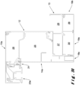
- FIG. 3B illustrates a second type of external pivot beam, wherein the pivot beam is intended to form a side wall 6. Identical elements will be indicated by the same numeral and are not described.
- the pivot beam of Figure 3B is designed to hold a roll-in/roll-out screen 6a serving as a side wall (see Figure 2A ) and arranged in the screen cavity 25.
- the main difference with the pivot beam of Figure 3A is the absence of support profile 17 and filler profile 18. Namely, these would disrupt the normal operation of the screen 6a.
- the slot 42 is provided for arranging therein a holder (not shown) which serves as an abutment for the screen 6a when it is rolled in. Alternatively, the slot 42 itself may serve as such a screen roller abutment.
- the wall 43 (which extends inwardly on the inner side of the front cover 14) and the wall 221 (which extends outwardly on the outer side of the inner gutter 27) may also serve as an abutment for the screen 6a.
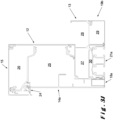
- Figure 3C illustrates a third type of external pivot beam, wherein the pivot beam is intended to form a sidewall 6. Identical elements will be identified by the same numeral and are not described.
- the pivot beam of Figure 3C is designed to cooperate with a stationary wall (see Figures 2H to 2J ).
- the main differences with the pivot beam of Figure 3A are the design of the front cover 14a and the filler element 18a and the presence of a drip profile 24 as alternative on the connection profile 16.
- the drip profile 24 has a substantially horizontal wall 450 which is provided on its top side with first connection means 35, in particular a hooking means formed by two hooks, corresponding to the first connection means 108 in the base profile 12.
- the drip profile 24 also has a second connection means 453, in particular a hook as the end of an elastically upright wall 454.
- This second connection means 453 engages a corresponding connection means 118 (see Figure 6A ), in particular a hook on the bottom side of the lower connection means 112, on the base profile 12.
- the connection means 35, 108, 118, 453 together ensure the attachment of the drip profile 24 to the base profile 12.
- the drip profile 24 is finished with an upright wall 452 extending downwardly from the horizontal wall 450.
- this upright wall 452 is located substantially in the same plane as the cover wall 402.
- a slot 451 is provided at the bottom side of the horizontal wall 450 which has the same function as slot 109 in the base profile 12, namely an attachment for the front cover 14a, in particular the end 37a thereof.
- the front cover 14a has again a substantially flat outer side, which, in this embodiment, does not lie in the same plane as the cover wall 402, but is located more towards the inner side of the external pivot beam 3.
- the distance between the outer side of the front cover 14a and the upright wall 100 of the base profile 12 is smaller than before.
- the stationary wall 6d is located between the outer side of the front cover 14a and the upright wall 452 of the drip profile 24 with its top side substantially against the bottom side of the horizontal wall 450.
- This also immediately explains the additional function of the drip profile 24, in particular the wall 452, namely, to prevent the incidence of precipitation on the top side of the stationary wall 6d, which precipitation may could damage, discoloration, etc. at the stationary wall 6d.
- the front cover 14a is provided on its inner side with a reinforcement 41a which, although the modified shape compared to the front cover 14, has the same function.
- a filler profile 18a is also provided on the bottom side of the external pivot beam 3. Although the design of the filler profile 18a is changed, compared to the filler profile 18 shown in Figure 3A , the function is unchanged, namely closing off the space between the front cover 14a and the double gutter profile 13. Further details are therefore not included.
- the stationary wall 6d is not transparent, it is not necessary to mount the front cover 14a on the external pivot beam 3. After all, the front cover 14a is not visible in such an embodiment.
- the filler profile 18a must be made slightly wider such that it fits closely with the stationary wall 6d such that, seen from the inside of the terrace canopy 1, the pivot beam 3 is finished almost without a visible opening between the pivot beam 3 and the stationary wall 6d.
- FIG 3D illustrates a fourth type of external pivot beam, wherein the pivot beam is intended to form a side wall 6.
- Identical elements will be identified by the same numeral and are not described. Changes have also been made to the design of the base profile 12', the double gutter profile 13', the front cover 14', the cover profile 15', the connection profile 16' and the support profile 17' without any change to the functionality such that the modified design is not explained in more detail. It should be noted, however, that connection means 108 which is formed by two hooks (see Figure 6A ) in base profile 12 is now formed by one hook 108'a and one abutment 108'b.
- the pivot beam of Figure 3D is designed to cooperate with a movable wall 6b, 6c (see Figures 2B , 2C and 2G ).
- the main difference with the pivot beam of Figure 3A is the presence of a wall profile 21 in space 29 below the external gutter 28. This also changes the design of the closure profile 19a.
- the closure profile 19a only serves to close off space 30 below the internal gutter 27.
- the closure profile 19a comprises a horizontal wall 440a which merges on its outwardly facing side into an upright wall 441a which, unlike upright wall 441, is located between the filler profile 18 and the lower outer branch 209 of the gutter profile 13'.
- the upper end of the upright wall 441a is connected to wall part 209b (see Figure 6B ), for example by means of rivets or the like.
- Connection means 446 is identical to the pivot beam of Figure 3A and is not further described.
- a connection means 445a is provided to cooperate with the lower inner connection means 216 for attaching the closure profile 19a to the double gutter profile 13'.
- the wall profile 21 is provided with a guide chamber 460 formed by two upright walls 461, 462 connected to a horizontal upper wall 463.
- the upright walls 461, 462 together form a rail 464 into which one or more rollers (not shown) can be movably mounted.
- the wall profile 21 is further provided with a lower wall 465 with an opening 469 therein which opens onto guide chamber 460. A portion of the rollers and/or the wall extends through the opening 469.
- connection means 468 is provided, in particular a hooking means, which is provided to cooperate with the lower inner connection means 216 for attaching the wall profile 21 to the double gutter profile 13'.
- connection means 467 corresponding to connection means 444 of closure profile 19
- a pin provided to cooperate with the inner connection means 215 for attaching the wall profile 21 to the double gutter profile 13'.
- the top wall 463 of the guide chamber 460 extends against the inner side wall 466.
- Figure 3E illustrates a fifth type of external pivot beam, wherein the pivot beam is intended to form a side wall 6. Identical elements will be identified by the same numeral and will not be described.
- the pivot beam of Figure 3E is designed to cooperate with a movable wall 6b, 6c (see Figures 2B and 2C ).
- the main difference with the pivot beam of Figure 3A is the presence of a wall profile 21 in space 30 below the internal gutter 27. This has also changed the design of the closure profile 19b.
- the closure profile 19b now only serves to close off space 29 below the external gutter 28.
- the closure profile 19b comprises a horizontal wall 440b which merges on its inwardly facing side into an upright wall 443, which is provided with a pin 444, identical as with the pivot beam of Figure 3A , such that a further description is unnecessary.
- the horizontal wall 440b is provided at its outwardly facing end with a connection means 445b, in particular a hooking means, provided to cooperate with the lower inner connection means 216 for attaching the closure profile 19b to the double gutter profile 13.
- the external pivot beam of Figure 3E serves for cooperation with a movable wall 6b.
- the wall profile 21a is provided with two guide chambers 460 which are formed in the same way as the guide chamber 460 of wall profile 21 described with reference to Figure 3D .
- the inner and outer upright walls 461, 462 which form the rails 464 and are connected to the horizontal wall 463.
- a horizontal wall portion 463a is also provided, connecting the horizontal walls 463 of the separate guide chambers 460.
- the lower wall 465a is correspondingly provided with two openings 469, one for each guide chamber 460.
- connection means 468a is provided at the inwardly facing end of the lower horizontal wall 465a, in particular a hooking means, which is provided to cooperate with the lower inner connection means 216 for attaching the wall profile 21a to the double gutter profile 13.
- an upright wall 470 is provided, which is located between the filler profile 18 and the lower outer branch 209 of the gutter profile 13.
- the upper end of the upright wall 470 is connected to wall part 209b (see Figure 6B ), for example by means of rivets or the like.
- connection means 471 which is similar to connection means 446 as with the pivot beam of Figure 3A and serves to cooperate with connection means 433 on filler profile 18 for their interconnection.
- each rail In view of the presence of two rails 464 in wall profile 21a, it is possible to provide in each rail one or two movable panels 6b which are slidable in the longitudinal direction of the pivot beam 3, for example by using rollers (not shown).
- the panels 6b in the different rail can pass along each other. In other words, this forms a side wall 6b as in Figures 2B and 2C with only two or four panels instead of the six panels shown there (three on either side of the terrace canopy 1).
- a combination can also be made of sliding panels 6b in one of the rails 464 and folding panels 6c in the other rail.
- Figure 3F illustrates a sixth type of external pivot beam, wherein the pivot beam is intended to form a sidewall 6. Identical elements will be identified by the same numeral and are not described.
- the pivot beam of Figure 3F is designed to cooperate with a movable wall 6b, 6c (see Figures 2B and 2C ).
- the main difference with the pivot beam of Figure 3E is the presence of a third rail 464 where normally the filler profile 18 is present.
- the wall profile 21b is provided with three guide chambers 460 which are formed in the same way as the guide chamber 460 of wall profile 21, 21a, described with reference to Figures 3D and 3E .
- the lower wall 465b is therefore correspondingly provided with three openings 469.
- the connection of the wall profile 21b on its inner side with the double gutter profile 13 is identical as for wall profile 21a and will not be described in more detail.
- connection of the wall profile 21b with the double gutter profile 13 is formed by an upright wall 472 which extends upwardly from the horizontal wall 463 of the most outwardly extending guide chamber 460.
- This upright wall 472 ends in an upper connection means 473, in particular a hooking means, which cooperates with the wall 221 (which extends outwardly on the outer side of the inner gutter 27).
- the lower end of the front cover 14 abuts against the outer end of the horizontal wall 465b of the wall profile 21b.
- each rail In view of the presence of three rails 464 in wall profile 21b, it is possible to provide in each rail one or two movable panels 6b which are slidable in the longitudinal direction of the pivot beam 3, for example by using rollers (not shown).
- the panels 6b in the different rail can pass along each other. In other words, this forms a side wall 6b as in Figures 2B and 2C .
- a combination can also be made of sliding panels 6b in two of the rails 464 and folding panels 6c in the other rail.
- Figure 3G illustrates a seventh type of external pivot beam, wherein the pivot beam is intended to form a sidewall 6. Identical elements will be identified by the same numeral and are not described.
- the pivot beam of Figure 3G is designed to cooperate with a movable wall 6b (see Figure 2D ).
- the main difference with the pivot beam of Figure 3E is the design of the wall profile 21c with respect to the wall profile 21a.
- the wall profile 21c comprises a horizontal upper wall 463c from which five upright walls 461c extend downwardly to form four guide chambers 460c.
- the most inwardly facing upright wall 461c is provided with a horizontal branch 465c comprising a connection means 468c, in particular a hooking means, which is provided to cooperate with the lower inner connection means 216 for the attachment of the wall profile 21c to the double gutter profile 13.
- connection means 471c is also provided which is similar to connection means 446 as with the pivot beam of Figure 3A and serves to cooperate with connection means 433 on filler profile 18 for their interconnection.
- the wall profile 21c is typically intended for slidable wall panels 6b that are thinner, in comparison to the wall profiles 21, 21a and 21b.
- the wall profile 21c is intended for glass wall panels in which a maximum of four (or eight) panels 6b can slide along each other, as shown in Figure 2D . Due to the lower weight of the wall panels 6b (in view of their relatively low thickness) it is possible to use less strong rails 464c, whereby wall profile 21c is compact such that more wall panels 6c can be provided in the transverse direction of the pivot beam 3.
- This compact wall profile 21c also allows other forms of wall infill, for instance a screen 6a, to be present in order to arrive at the terrace canopy shown in Figure 2D .
- rollers are typically provided on the bottom side of the panels on the ground guide 99 such that the guide in the rails 460c can be embodied more compact or even omitted altogether.
- FIG. 3H illustrates an eighth type of external pivot beam, wherein the pivot beam is intended to form a sidewall 6. Identical elements will be identified by the same numeral and are not described.
- the pivot beam of Figure 3H is designed to cooperate with a movable wall 6b, 6c (see Figures 2E and 2F ).
- the main difference with the pivot beam of Figure 3A is the presence of a wall profile 20 that is positioned outwardly relative to the front cover 14a', which therefore also has a modified design, in particular the same design as the front cover 14a with a stationary wall infill, described with reference to Figure 3C , such that a further description is not included here.
- the front cover 14a' is located at a different distance from the upright wall 100 of the base profile 12 compared to the front cover 14a of the pivot beam 3, shown in Figure 3C .
- the design of the cover profile 15a is also changed.
- the horizontal wall 400a has a longer length such that the distance between the pins 403, 404 is larger and such that the outer upright wall 402 is at a larger distance from the upright wall 100 of the base profile 12. This longer length allows to integrate the wall profile 20 into the design of the pivot beam 3 without adversely affecting the quality of the finish.
- the wall profile 20 includes a guide chamber 480 which is identical to that of wall profiles 21, 21a and 21b.
- the guide chamber 480 is therefore limited by inner and outer upright walls 481, 482, an upper horizontal wall 483 connecting the upright walls 481, 482, and a lower wall 485 having an opening 496 therein.
- the upright walls 481, 482 together form a rail 484 into which one or more rollers (not shown) can be movably arranged. A portion of the rollers and/or the wall extends through the opening 496.
- the lower wall 485 has, on its inwardly-facing end, a slot 490 for receiving the end 37a of the front cover 14a' for the attachment of the front cover 14a' to the wall profile 20.
- This slot 490 is, in particular, formed by a downwardly extending branch 499 that departs from the bottom side of the lower wall 485.
- a downwardly extending branch 499 that departs from the bottom side of the lower wall 485.
- the upright wall 486, in particular the lower part thereof is provided on its inner side with a first inner connection means 487, in particular a hooking means.
- the first inner connection means 487 serves to cooperate with the lower connection means 112 (see Figure 6A ) for connecting the wall profile 20 to the base profile 12.
- the bend 497 allows the upper part of the wall 486 to be positioned more outwardly and to abut against the branch 114. At the top of the upright wall 486 it merges into an upper horizontal wall 488. Also, the upper wall 483 of the guide chamber 480 is connected to this upper wall 488 by support member 495.
- the horizontal wall 488 is on its inner end provided with a second inner connection means 489, in particular a hooking means, which hooks over the second upper connection means 113 for connecting the wall profile 20 to the base profile 12.
- the outer wall 481 of the guide chamber 480 also has an upward upright branch 492 which is provided on its top side with an upper connection means 491, in particular, a female pin connection means.
- the upper connection means 491 is used to connect the cover profile 15a via pin 404.
- a connection wall 494 is provided between the horizontal wall 488 and the upright branch 492 for the strength and bearing capacity of the wall profile 20.
- a branch 493 is also provided on the outer side of the upright branch 492.
- the lower wall 485 is provided on its outwardly facing side with an upright finishing wall 498 which is located in the same plane as the outer side wall 402 of the cover profile 15a.
- An opening 33a is provided between walls 402, 498.
- this rail 484 is to hold a foldable side wall, as shown in Figures 2E and 2F .
- a single rail 484 can also be used to hold one or two sliding side wall panels.
- the wall profile 20 can also be provided with several mutually parallel chambers for guiding several wall panels.
- Figure 3I illustrates a ninth type of external pivot beam, wherein the pivot beam is intended to form a side wall 6. Identical elements will be identified by the same numeral and are not described.
- the pivot beam shown in Figure 3I has a combined functionality, namely that of the pivot beams shown in Figures 3C and 3H .
- the external pivot beam 3 has as side wall infill 6 both a portion with a fixed wall 6d and a portion with a movable, in particular a foldable, side wall 6c.
- a fixed wall 6d is provided on one side of a side of the terrace canopy 1, while a foldable side wall 6c is present on the other side of the same side.
- the front cover 14a and the drip profile 24 of the pivot beam of Figure 3I are identical to those described with reference to Figure 3C and the cover section 15a is identical to that described for the pivot beam of Figure 3H . A further description is therefore not included here.
- the wall profile 20a is substantially identical to what was described with reference to Figure 3H .
- the only difference is the absence of branch 499 which served as attachment for the front cover 14a. Now, this branch 499 is not necessary since the front cover 14a is held by the drip profile 24 and is closer to the upright wall 100 of the base profile 12 such that there is sufficient space for placing a fixed wall 6d.
- Figure 3J illustrates a tenth type of external pivot beam, wherein the pivot beam is intended to form a side wall 6. Identical elements will be identified by the same numeral and are not described.
- the pivot beam shown in Figure 3J has a combined functionality, namely that of the pivot beams shown in Figures 3C and 3E .
- the external pivot beam 3 has as side wall infill 6 both a portion with a fixed wall 6d and a portion with a movable, in particular a slidable, side wall 6b.
- one side of a side of the terrace canopy 1 is provided with a fixed wall 6d, while on the other side of the same side there is a slidable side wall 6b, in particular formed by two wall panels.
- Figure 3K illustrates an eleventh type of external pivot beam, wherein the pivot beam serves for holding a lighting. Identical elements will be identified by the same numeral and are not described.
- the pivot beam of Figure 3K is substantially the same as the one shown in Figure 3D with the difference that the wall profile 21 has been replaced by a lighting holder profile 10.
- the lighting holder profile 10 comprises two spaces 500, 501 in which lighting (not shown), such as one or more lamps, LED lighting, etc. can be installed.
- the space 500 can be used to illuminate the space below the terrace canopy 1, while the space 501 allows to illuminate the area below the pivot beam 3.
- the space 500 is substantially U-shaped and comprises an upright central wall 502, a top wall 503 and a bottom wall 504.
- the top wall 503 is provided at its end with an upright inner branch 505 having a connection means 506 thereon (corresponding to connection means 444 of closure profile 19), in particular a pin, provided to cooperate with the inner connection means 215 for attaching the lighting holder profile 10 to the double gutter profile 13'.
- the space 501 is substantially U-shaped and comprises an upright central wall 502, an top wall 507 and an outer side wall 508.
- the outer side wall 508 is provided at its bottom end with a connection means 509, in particular a hooking means, which is provided to cooperate with the lower inner connection means 216 for attaching the lighting holder profile 10 to the double gutter profile 13'.
- additional mounting walls 510, 511 are also provided on which, among other things, the lighting can be attached. It is also possible to arrange diffusers and/or other elements in the spaces 500, 501 for optimizing the light quality. Furthermore, it should be understood that also only one of the spaces 500, 501 can be present.
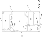
- FIG 4 illustrates a design of a tension beam 5.
- the tension beam 5 shown is intended not to be provided with a wall infill 6.
- the tension beam 5 shown comprises a base profile 12" and a single gutter profile 11 which are interconnected.
- the single gutter profile 11 is also shown per se in Figure 6C . It is to be understood that, in embodiments not shown, the tension beam can be suited and intended for receiving and/or holding a wall infill by using the profiles shown in Figures 3B , 3C , 3E , 3F , 3G , 3H , 3I and/or 3J .
- the tension beam 5 shown is generally the same as the pivot beam shown in Figure 3A but with a different type of gutter profile, namely a single gutter profile 11 instead of a double gutter profile 13.
- the profiles 12", 14", 16", 18" of the tension beam 5 have a slightly different design, it should be understood that they are interchangeable with the profiles 12, 14, 16, 18, 12', 14', 16', 18' described above. It is also possible to replace one or more of the profiles 12, 14, 16, 18, 12', 14', 16', 18' in the external pivot beams 3 described above with its modified form of the same profile shown in the tension beam 5 of Figure 4 . Some of the modifications are briefly described.
- Notch 110 is not provided in the base profile 12", but this functionality is taken over by hook 108" which protrudes downwardly with respect to the horizontal wall 101".
- the branch 415" on connection profile 16" has been modified accordingly.
- the inner upright wall 432" of filler profile 18" is shorter and is directly connected to the upright outer side wall 441a of the closure profile 19a instead of on the gutter profile.
- the design of the slot 42" has been changed.
- the single gutter profile 11 is shown in more detail in Figure 6C .
- the design at the top and the outer side of the gutter profiles 11, 13 is identical, such that a further description of elements 300 to 312 and 317 to 321 is superfluous.
- the modifications of the single gutter profile 11 compared to the double gutter profile 13 are therefore located on the inner side of this profile, where now no external gutter 28 is present.
- An additional upright wall part 322 is therefore placed, which is parallel to the intermediate wall 311 (which, for the sake of clarity, in the embodiment of a single gutter profile, is not provided with openings).
- the upright walls 302, 312, 322 together form the inner upright wall 323 of the single gutter profile 11.
- This is also the externally visible wall, seen by someone located below the terrace canopy 1.
- the lower inner connection means 316 particularly a hooking means, is also substantially identical to connection means 216, with the difference that the hook only extends outwardly such that the finish of wall 323 is uninterrupted.
- a tension beam 5 Although only one embodiment of a tension beam 5 has been shown, it is understood that the only difference between an external pivot beam 3 and a tension beam 5 is the shape of the gutter profile 11, 13. Hence, the invention also relates to multiple tension beams having the same functionality of the external pivot beams shown in Figures 3A to 3C and 3E to 3J where the double gutter profile 13 is replaceable by the single gutter profile 11 of Figure 6C .
- Figure 5 illustrates a central pivot beam 4. Since the central pivot beam 4 is centrally located in the terrace canopy 1, it is not the intention that a side wall can be located below the beam 4, which changes the design of a whole number of profiles. Of course, it cannot be ruled out that a wall infill may be present below the central pivot beam 4.
- the central pivot beam 4 is constructed from a limited number of profiles, namely a base profile 22, a gutter profile 23, a cover profile 15b and two closure profiles 19b.
- the base profile 22 has a symmetrical construction and is connected to the gutter profile 23 by means of connections 58, 59. Connections 58, 59 have a different design, whereby connection 58 is shown as a hook connection. However, these connections can be identical to each other.
- the base profile 22 is sealed by a cover profile 15b by means of pin connections 57.
- the gutter profile 23 comprises two external gutters 28 and the central gutter 27 which are separated by intermediate walls 56. For finishing at the bottom side below the external gutters 28, use is made of two closure profiles 19b identical to the one described with reference to Figure 3E .
- connection means 55 in particular a female pin connection means, below the external gutters 28, which cooperates with pin 444, and a lower connection means 54, in particular a hooking means, forming the end of the branch 53 and cooperating with hook 445b.
- connection means 55 in particular a female pin connection means, below the external gutters 28, which cooperates with pin 444
- lower connection means 54 in particular a hooking means, forming the end of the branch 53 and cooperating with hook 445b.
- the central pivot beam 4 is also provided with screw channels 50 for screwing a headboard onto an end of this beam 4 by means of screws or bolts.
- finishing profile 19b can also be replaced by LED-holder profile 10, described with reference to Figure 3K . If necessary, it is also possible to replace the finishing profile 19b with wall profile 21 described with reference to Figure 3D .
- the space 30 below the internal gutter 27 may also be used for a wall profile.
Landscapes
- Engineering & Computer Science (AREA)
- Architecture (AREA)
- Civil Engineering (AREA)
- Structural Engineering (AREA)
- Roof Covering Using Slabs Or Stiff Sheets (AREA)
- Building Awnings And Sunshades (AREA)
- Support Devices For Sliding Doors (AREA)
- Acyclic And Carbocyclic Compounds In Medicinal Compositions (AREA)
- Medicines That Contain Protein Lipid Enzymes And Other Medicines (AREA)
- Transition And Organic Metals Composition Catalysts For Addition Polymerization (AREA)
- Body Structure For Vehicles (AREA)
Claims (14)
- Terrassenüberdachung (1), die einen Balken (3; 5) umfasst, wobei der Balken eine Oberseite, eine Unterseite, eine Innenseite und eine Außenseite aufweist und einen Basisteil umfasst, der in seinem Querschnitt bereitgestellt ist mit:- einem Sichtschutzhohlraum (25), der konfiguriert ist, um eine Sichtschutzrolle zu halten, wobei der Sichtschutzhohlraum durch eine aufrechte innere Seitenwand (100) und eine horizontale obere Wand (101), die sich von der aufrechten inneren Seitenwand in Richtung der Außenseite des Balkens erstreckt, begrenzt ist;- einer aufrechten äußeren Seitenwand (111), die sich vom Ende der horizontalen oberen Wand erstreckt und oben mit einem ersten oberen Verbindungsmittel (113) bereitgestellt ist; und- einem Innenraum (26) oberhalb des Sichtschutzhohlraums,wobei die aufrechte äußere Seitenwand (111) auf ihrer nach außen gewandten Seite mit einem ersten Verbindungsmittel (112) bereitgestellt ist,dadurch gekennzeichnet, dass der Balken weiter bereitgestellt ist mit: einem Wandprofil (20) und einem zweiten Verschlussprofil (15a), wobei sich das Wandprofil (20) an der Außenseite der aufrechten äußeren Seitenwand befindet und konfiguriert ist, um ein Wandpaneel (6b; 6c; 6d) zu führen und/oder zu halten, und mit einem ersten komplementären Verbindungsmittel (489), einem zweiten komplementären Verbindungsmittel (487) und einem ersten oberen Verbindungsmittel (491) bereitgestellt ist, wobei das Wandprofil (20) durch Verbinden seines ersten komplementären Verbindungsmittels (489) mit dem ersten oberen Verbindungsmittel (113), und seines zweiten komplementären Verbindungsmittels mit dem ersten Verbindungsmittel (112) mit dem Basisglied (12) verbunden wird, wobei das zweite Verschlussprofil (15a) den Innenraum abschließt und mit einem ersten komplementären Verbindungsmittel (404) bereitgestellt ist, wobei das zweite Verschlussprofil (15a) durch Verbinden seines ersten komplementären Verbindungsmittels (404) mit dem ersten oberen Verbindungsmittel (491) des Wandprofils (20) mit dem Wandprofil (20) verbunden ist, unddadurch, dass das Wandprofil (20) und das zweite Verschlussprofil (15a) entfernt werden können und das zweite Verschlussprofil (15a) durch ein erstes Verschlussprofil (15) ersetzt werden kann und umgekehrt, wobei das erste Verschlussprofil (15) den Innenraum abschließen kann und mit einem ersten komplementären Verbindungsmittel (404) bereitgestellt ist, wobei das erste Verschlussprofil (15) imstande ist, durch Verbinden seines ersten komplementären Verbindungsmittels mit dem ersten oberen Verbindungsmittel mit dem Basisteil (12) verbunden zu werden.
- Terrassenüberdachung (1) nach Anspruch 1, dadurch gekennzeichnet, dass die aufrechte innere Seitenwand (100) oben mit einem zweiten oberen Verbindungsmittel (102) bereitgestellt ist, wobei das erste Verschlussprofil (15) und das zweite Verschlussprofil (15a) jeweils mit einem zweiten komplementären Verbindungsmittel (403) bereitgestellt sind, wobei das erste Verschlussprofil (15) durch Verbinden seines zweiten komplementären Verbindungsmittels mit dem zweiten oberen Verbindungsmittel (102) mit dem Basisteil (12) verbunden wird, und wobei das zweite Verschlussprofil (15a) durch Verbinden seines zweiten komplementären Verbindungsmittels (403) mit dem zweiten oberen Verbindungsmittel (102) mit dem Basisglied (12) verbunden wird.
- Terrassenüberdachung (1) nach Anspruch 2, dadurch gekennzeichnet, dass das zweite obere Verbindungsmittel (102) ein weibliches Stiftverbindungsmittel umfasst, und dadurch, dass das zweite komplementäre Verbindungsmittel ein männliches Stiftverbindungsmittel (403) umfasst.
- Terrassenüberdachung (1) nach einem der vorstehenden Ansprüche, dadurch gekennzeichnet, dass das erste obere Verbindungsmittel (113) ein weibliches Stiftverbindungsmittel umfasst, und dadurch, dass das erste komplementäre Verbindungsmittel (404) jedes Verschlussprofils ein männliches Stiftverbindungsmittel umfasst.
- Terrassenüberdachung (1) nach einem der vorstehenden Ansprüche, dadurch gekennzeichnet, dass das erste obere Verbindungsmittel (113) und das erste Verbindungsmittel (112) jeweils ein Hakenelement umfassen, und dass das erste komplementäre Verbindungsmittel (489) und das zweite komplementäre Verbindungsmittel (487) des Wandprofils ein Hakenelement umfassen.
- Terrassenüberdachung (1) nach einem der vorstehenden Ansprüche, dadurch gekennzeichnet, dass das erste obere Verbindungsmittel (113) ein weibliches Stiftverbindungsmittel und ein Hakenelement umfasst.
- Terrassenüberdachung (1) nach einem der vorstehenden Ansprüche, dadurch gekennzeichnet, dass der Innenraum (26) durch die horizontale obere Wand (101), die aufrechte äußere Seitenwand (111) und die aufrechte innere Seitenwand (100a) begrenzt wird.
- Terrassenüberdachung (1) nach einem der vorstehenden Ansprüche, dadurch gekennzeichnet, dass das Wandprofil eine Schiene (20) umfasst, die konfiguriert ist, um mindestens ein Wandpaneel (6b; 6c) zu halten und zu führen.
- Terrassenüberdachung (1) nach einem der vorstehenden Ansprüche, dadurch gekennzeichnet, dass die nach außen gewandte Oberfläche (402) des zweiten Verschlussprofils (15a) und die nach außen gewandte Oberfläche der äußeren Seitenwand (498) des Wandprofils (20) im Wesentlichen in derselben Ebene liegen.
- Terrassenüberdachung (1) nach einem der vorstehenden Ansprüche, dadurch gekennzeichnet, dass der Balken einen Regenrinnenteil (11; 13) umfasst, der sich unterhalb des Basisteils (12) befindet und konfiguriert ist, um den auf die Terrassenüberdachung (1) fallenden Niederschlag zu einem vorderen Ende des Balkens abzuleiten.
- Terrassenüberdachung (1) nach Anspruch 10, dadurch gekennzeichnet, dass der Basisteil und der Regenrinnenteil als getrennte Profile gebildet sind, wobei die aufrechte innere Seitenwand (100) des Basisprofils (12) unten mit mindestens einem, vorzugsweise mindestens zwei Verbindungsmitteln (103,105) bereitgestellt ist, und dadurch, dass das Regenrinnenprofil mit mindestens einem, vorzugsweise mindestens zwei entsprechenden Verbindungsmitteln (203, 205; 303, 305) zum Verbinden des Basisprofils mit dem Regenrinnenprofil bereitgestellt ist.
- Terrassenüberdachung (1) nach einem der vorstehenden Ansprüche, dadurch gekennzeichnet, dass die horizontale obere Wand (101) nahe ihrem Ende mit einem zweiten Verbindungsmittel bereitgestellt ist.
- Terrassenüberdachung (1) nach Anspruch 12, dadurch gekennzeichnet, dass das zweite Verbindungsmittel eine Vielzahl von Verbindungsmitteln (108, 109) umfasst.
- Terrassenüberdachung (1) nach einem der vorstehenden Ansprüche, dadurch gekennzeichnet, dass das Wandprofil (20) eine Schiene (480) umfasst, die konfiguriert ist, um mindestens einen Wandteil zu führen.
Applications Claiming Priority (2)
| Application Number | Priority Date | Filing Date | Title |
|---|---|---|---|
| BE20205265A BE1028223B1 (nl) | 2020-04-21 | 2020-04-21 | Een ligger voor een overkapping |
| PCT/IB2021/053278 WO2021214675A1 (en) | 2020-04-21 | 2021-04-21 | Terrace canopy |
Publications (3)
| Publication Number | Publication Date |
|---|---|
| EP4139539A1 EP4139539A1 (de) | 2023-03-01 |
| EP4139539C0 EP4139539C0 (de) | 2025-04-02 |
| EP4139539B1 true EP4139539B1 (de) | 2025-04-02 |
Family
ID=70470723
Family Applications (2)
| Application Number | Title | Priority Date | Filing Date |
|---|---|---|---|
| EP21727218.6A Active EP4139538B1 (de) | 2020-04-21 | 2021-04-21 | Terrassenüberdachung |
| EP21727219.4A Active EP4139539B1 (de) | 2020-04-21 | 2021-04-21 | Terrassenüberdachung |
Family Applications Before (1)
| Application Number | Title | Priority Date | Filing Date |
|---|---|---|---|
| EP21727218.6A Active EP4139538B1 (de) | 2020-04-21 | 2021-04-21 | Terrassenüberdachung |
Country Status (9)
| Country | Link |
|---|---|
| US (2) | US12123195B2 (de) |
| EP (2) | EP4139538B1 (de) |
| JP (1) | JP2023524644A (de) |
| AU (1) | AU2021261741A1 (de) |
| BE (1) | BE1028223B1 (de) |
| CA (1) | CA3175583A1 (de) |
| ES (1) | ES2988512T3 (de) |
| HU (1) | HUE067111T2 (de) |
| WO (2) | WO2021214675A1 (de) |
Families Citing this family (7)
| Publication number | Priority date | Publication date | Assignee | Title |
|---|---|---|---|---|
| BR112021014841A2 (pt) * | 2019-02-07 | 2021-10-05 | Zephyros, Inc. | Membro estrutural |
| BE1028728B1 (nl) * | 2020-10-22 | 2022-05-23 | Renson Sunprotection Screens | Dakinrichting voor een overkapping, set onderdelen voor het opbouwen van de dakinrichting, en overkapping omvattende de dakinrichting |
| DE102021111373A1 (de) * | 2021-05-03 | 2022-11-03 | Stobag Ag | Dachkonstruktion |
| BE1029716B1 (nl) * | 2021-08-27 | 2023-03-27 | Renson Sunprotection Screens | Een terrasoverkapping en werkwijze voor het vervaardigen daarvan |
| US20230322343A1 (en) * | 2022-04-12 | 2023-10-12 | Touchless Cover, LLC | Cover extension |
| EP4403726A1 (de) * | 2023-01-20 | 2024-07-24 | Adiwatt | Schattenspendende anlage |
| WO2024156277A1 (en) * | 2023-01-27 | 2024-08-02 | Zhejiang Zhengte Co., Ltd. | Cantilever umbrella |
Family Cites Families (17)
| Publication number | Priority date | Publication date | Assignee | Title |
|---|---|---|---|---|
| US3222841A (en) * | 1962-10-08 | 1965-12-14 | Aire Lite Ind Inc | Screen enclosure |
| NL8302886A (nl) * | 1983-08-17 | 1985-03-18 | Louis Boeters | Zonnewering. |
| DE59308315D1 (de) * | 1992-01-13 | 1998-04-30 | Cedis Licensing Gmbh | Profilmontageelement für die aufnahme und halterung verschiedener befestigungs- und/oder bewegungselemente einer markise |
| BE1009421A3 (nl) * | 1995-06-02 | 1997-03-04 | Brutsaert Accessories Nv | Oprolbare luifel. |
| US7246469B2 (en) * | 2002-12-16 | 2007-07-24 | Park Lane Conservatories Ltd. | Multi-piece eaves beam for preassembled glazed roof system |
| IT1394762B1 (it) * | 2009-06-18 | 2012-07-13 | Bat Spa | Dispositivo di protezione per un profilo guida di una tenda ad attico |
| FR2958319B1 (fr) | 2010-04-02 | 2015-12-11 | Profils Systemes | Veranda a integration amelioree du volet roulant et volet roulant adapte |
| BE1019767A3 (nl) | 2011-01-14 | 2012-12-04 | Brustor Nv | Zonwering. |
| DE202012102413U1 (de) * | 2012-06-29 | 2012-08-24 | Heim & Haus Holding Gmbh | Tragkonstruktion für ein Dach und freistehendes Beschattungssystem mit einer derartigen Tragkonstruktion |
| BE1021781B1 (nl) * | 2013-11-19 | 2016-01-18 | Renson Sunprotection-Screens Nv | Kolom voor het ondersteunen van een overkapping en schermconstructie omvattende een dergelijke kolom |
| BE1021793B1 (nl) * | 2014-01-10 | 2016-01-18 | Renson Sunprotection Screens Nv | Scherminrichting |
| EP3636850B1 (de) | 2017-06-09 | 2023-06-07 | C3 Systems, S.L. | Pergola |
| EP3486406B1 (de) | 2017-11-21 | 2020-09-09 | GIBUS S.p.A. | Aussenmarkise und verfahren zum betrieb der besagten markise |
| IT201800001632A1 (it) | 2018-01-22 | 2019-07-22 | Brianzatende S R L | Struttura di copertura per esterni |
| US10914067B2 (en) * | 2018-03-05 | 2021-02-09 | Integrity Windows, Llc | Integrated fenestration wall assembly |
| BE1026543B1 (nl) * | 2019-02-15 | 2020-03-10 | Renson Sunprotection Screens Nv | Zijgeleider voor scherminrichting |
| US11180953B2 (en) * | 2019-04-26 | 2021-11-23 | WINCO Window Company, Inc. | Visual security and environmental self adjusting window |
-
2020
- 2020-04-21 BE BE20205265A patent/BE1028223B1/nl active IP Right Grant
-
2021
- 2021-04-21 ES ES21727218T patent/ES2988512T3/es active Active
- 2021-04-21 EP EP21727218.6A patent/EP4139538B1/de active Active
- 2021-04-21 US US17/919,835 patent/US12123195B2/en active Active
- 2021-04-21 WO PCT/IB2021/053278 patent/WO2021214675A1/en not_active Ceased
- 2021-04-21 AU AU2021261741A patent/AU2021261741A1/en not_active Abandoned
- 2021-04-21 JP JP2022563167A patent/JP2023524644A/ja active Pending
- 2021-04-21 HU HUE21727218A patent/HUE067111T2/hu unknown
- 2021-04-21 EP EP21727219.4A patent/EP4139539B1/de active Active
- 2021-04-21 US US17/919,841 patent/US12054950B2/en active Active
- 2021-04-21 WO PCT/IB2021/053275 patent/WO2021214673A1/en not_active Ceased
- 2021-04-21 CA CA3175583A patent/CA3175583A1/en active Pending
Also Published As
| Publication number | Publication date |
|---|---|
| CA3175583A1 (en) | 2021-10-28 |
| EP4139538B1 (de) | 2024-05-15 |
| EP4139539A1 (de) | 2023-03-01 |
| EP4139539C0 (de) | 2025-04-02 |
| HUE067111T2 (hu) | 2024-09-28 |
| BE1028223B1 (nl) | 2021-11-22 |
| EP4139538A1 (de) | 2023-03-01 |
| WO2021214673A1 (en) | 2021-10-28 |
| US12054950B2 (en) | 2024-08-06 |
| AU2021261741A1 (en) | 2022-11-17 |
| JP2023524644A (ja) | 2023-06-13 |
| US20230151610A1 (en) | 2023-05-18 |
| US20230151614A1 (en) | 2023-05-18 |
| BE1028223A1 (nl) | 2021-11-19 |
| EP4139538C0 (de) | 2024-05-15 |
| US12123195B2 (en) | 2024-10-22 |
| ES2988512T3 (es) | 2024-11-20 |
| WO2021214675A1 (en) | 2021-10-28 |
Similar Documents
| Publication | Publication Date | Title |
|---|---|---|
| EP4139539B1 (de) | Terrassenüberdachung | |
| EP4139531B1 (de) | Terrassenüberdachung | |
| WO2021214677A1 (en) | Terrace canopy | |
| EP4392626B1 (de) | Terrassenüberdachung und verfahren zur herstellung davon | |
| EP4139530B1 (de) | Terrassenüberdachung | |
| EP4139537B1 (de) | Terrassenüberdachung | |
| US20240141650A1 (en) | Roof arrangement for a terrace canopy, kit of parts for building the roof arrangement, and terrace canopy comprising the roof arrangement | |
| EP4352319B1 (de) | Terrassenüberdachung |
Legal Events
| Date | Code | Title | Description |
|---|---|---|---|
| STAA | Information on the status of an ep patent application or granted ep patent |
Free format text: STATUS: UNKNOWN |
|
| STAA | Information on the status of an ep patent application or granted ep patent |
Free format text: STATUS: THE INTERNATIONAL PUBLICATION HAS BEEN MADE |
|
| PUAI | Public reference made under article 153(3) epc to a published international application that has entered the european phase |
Free format text: ORIGINAL CODE: 0009012 |
|
| STAA | Information on the status of an ep patent application or granted ep patent |
Free format text: STATUS: REQUEST FOR EXAMINATION WAS MADE |
|
| 17P | Request for examination filed |
Effective date: 20221004 |
|
| AK | Designated contracting states |
Kind code of ref document: A1 Designated state(s): AL AT BE BG CH CY CZ DE DK EE ES FI FR GB GR HR HU IE IS IT LI LT LU LV MC MK MT NL NO PL PT RO RS SE SI SK SM TR |
|
| DAV | Request for validation of the european patent (deleted) | ||
| DAX | Request for extension of the european patent (deleted) | ||
| RAP3 | Party data changed (applicant data changed or rights of an application transferred) |
Owner name: RENSON OUTDOOR NV |
|
| GRAP | Despatch of communication of intention to grant a patent |
Free format text: ORIGINAL CODE: EPIDOSNIGR1 |
|
| STAA | Information on the status of an ep patent application or granted ep patent |
Free format text: STATUS: GRANT OF PATENT IS INTENDED |
|
| INTG | Intention to grant announced |
Effective date: 20250107 |
|
| GRAS | Grant fee paid |
Free format text: ORIGINAL CODE: EPIDOSNIGR3 |
|
| GRAA | (expected) grant |
Free format text: ORIGINAL CODE: 0009210 |
|
| STAA | Information on the status of an ep patent application or granted ep patent |
Free format text: STATUS: THE PATENT HAS BEEN GRANTED |
|
| AK | Designated contracting states |
Kind code of ref document: B1 Designated state(s): AL AT BE BG CH CY CZ DE DK EE ES FI FR GB GR HR HU IE IS IT LI LT LU LV MC MK MT NL NO PL PT RO RS SE SI SK SM TR |
|
| REG | Reference to a national code |
Ref country code: GB Ref legal event code: FG4D |
|
| REG | Reference to a national code |
Ref country code: CH Ref legal event code: EP |
|
| REG | Reference to a national code |
Ref country code: IE Ref legal event code: FG4D |
|
| REG | Reference to a national code |
Ref country code: DE Ref legal event code: R096 Ref document number: 602021028518 Country of ref document: DE |
|
| U01 | Request for unitary effect filed |
Effective date: 20250415 |
|
| U07 | Unitary effect registered |
Designated state(s): AT BE BG DE DK EE FI FR IT LT LU LV MT NL PT RO SE SI Effective date: 20250423 |
|
| PGFP | Annual fee paid to national office [announced via postgrant information from national office to epo] |
Ref country code: CH Payment date: 20250501 Year of fee payment: 5 |
|
| U20 | Renewal fee for the european patent with unitary effect paid |
Year of fee payment: 5 Effective date: 20250627 |
|
| PG25 | Lapsed in a contracting state [announced via postgrant information from national office to epo] |
Ref country code: ES Free format text: LAPSE BECAUSE OF FAILURE TO SUBMIT A TRANSLATION OF THE DESCRIPTION OR TO PAY THE FEE WITHIN THE PRESCRIBED TIME-LIMIT Effective date: 20250402 |
|
| PG25 | Lapsed in a contracting state [announced via postgrant information from national office to epo] |
Ref country code: GR Free format text: LAPSE BECAUSE OF FAILURE TO SUBMIT A TRANSLATION OF THE DESCRIPTION OR TO PAY THE FEE WITHIN THE PRESCRIBED TIME-LIMIT Effective date: 20250703 Ref country code: NO Free format text: LAPSE BECAUSE OF FAILURE TO SUBMIT A TRANSLATION OF THE DESCRIPTION OR TO PAY THE FEE WITHIN THE PRESCRIBED TIME-LIMIT Effective date: 20250702 |
|
| PG25 | Lapsed in a contracting state [announced via postgrant information from national office to epo] |
Ref country code: PL Free format text: LAPSE BECAUSE OF FAILURE TO SUBMIT A TRANSLATION OF THE DESCRIPTION OR TO PAY THE FEE WITHIN THE PRESCRIBED TIME-LIMIT Effective date: 20250402 |
|
| PG25 | Lapsed in a contracting state [announced via postgrant information from national office to epo] |
Ref country code: HR Free format text: LAPSE BECAUSE OF FAILURE TO SUBMIT A TRANSLATION OF THE DESCRIPTION OR TO PAY THE FEE WITHIN THE PRESCRIBED TIME-LIMIT Effective date: 20250402 |
|
| PG25 | Lapsed in a contracting state [announced via postgrant information from national office to epo] |
Ref country code: RS Free format text: LAPSE BECAUSE OF FAILURE TO SUBMIT A TRANSLATION OF THE DESCRIPTION OR TO PAY THE FEE WITHIN THE PRESCRIBED TIME-LIMIT Effective date: 20250702 |
|
| PG25 | Lapsed in a contracting state [announced via postgrant information from national office to epo] |
Ref country code: IS Free format text: LAPSE BECAUSE OF FAILURE TO SUBMIT A TRANSLATION OF THE DESCRIPTION OR TO PAY THE FEE WITHIN THE PRESCRIBED TIME-LIMIT Effective date: 20250802 |