EP4403726A1 - Schattenspendende anlage - Google Patents
Schattenspendende anlage Download PDFInfo
- Publication number
- EP4403726A1 EP4403726A1 EP23305069.9A EP23305069A EP4403726A1 EP 4403726 A1 EP4403726 A1 EP 4403726A1 EP 23305069 A EP23305069 A EP 23305069A EP 4403726 A1 EP4403726 A1 EP 4403726A1
- Authority
- EP
- European Patent Office
- Prior art keywords
- posts
- balancing
- wall
- post
- roof structure
- Prior art date
- Legal status (The legal status is an assumption and is not a legal conclusion. Google has not performed a legal analysis and makes no representation as to the accuracy of the status listed.)
- Pending
Links
- 238000004873 anchoring Methods 0.000 claims abstract description 13
- 230000000694 effects Effects 0.000 description 4
- 229910003460 diamond Inorganic materials 0.000 description 3
- 239000010432 diamond Substances 0.000 description 3
- 238000009434 installation Methods 0.000 description 3
- 230000003042 antagnostic effect Effects 0.000 description 2
- 238000005452 bending Methods 0.000 description 2
- 230000008901 benefit Effects 0.000 description 2
- 230000000903 blocking effect Effects 0.000 description 2
- 238000007664 blowing Methods 0.000 description 2
- 238000000034 method Methods 0.000 description 2
- 238000007789 sealing Methods 0.000 description 2
- 238000009416 shuttering Methods 0.000 description 2
- 230000002238 attenuated effect Effects 0.000 description 1
- 230000004888 barrier function Effects 0.000 description 1
- 238000010276 construction Methods 0.000 description 1
- 238000005553 drilling Methods 0.000 description 1
- 230000005484 gravity Effects 0.000 description 1
- 230000007246 mechanism Effects 0.000 description 1
- 239000000203 mixture Substances 0.000 description 1
- 238000012986 modification Methods 0.000 description 1
- 230000004048 modification Effects 0.000 description 1
- 230000000737 periodic effect Effects 0.000 description 1
- 230000009467 reduction Effects 0.000 description 1
- 230000002787 reinforcement Effects 0.000 description 1
- 230000035945 sensitivity Effects 0.000 description 1
- 239000007787 solid Substances 0.000 description 1
Images


Classifications
-
- H—ELECTRICITY
- H02—GENERATION; CONVERSION OR DISTRIBUTION OF ELECTRIC POWER
- H02S—GENERATION OF ELECTRIC POWER BY CONVERSION OF INFRARED RADIATION, VISIBLE LIGHT OR ULTRAVIOLET LIGHT, e.g. USING PHOTOVOLTAIC [PV] MODULES
- H02S20/00—Supporting structures for PV modules
- H02S20/20—Supporting structures directly fixed to an immovable object
- H02S20/22—Supporting structures directly fixed to an immovable object specially adapted for buildings
- H02S20/23—Supporting structures directly fixed to an immovable object specially adapted for buildings specially adapted for roof structures
-
- H—ELECTRICITY
- H02—GENERATION; CONVERSION OR DISTRIBUTION OF ELECTRIC POWER
- H02S—GENERATION OF ELECTRIC POWER BY CONVERSION OF INFRARED RADIATION, VISIBLE LIGHT OR ULTRAVIOLET LIGHT, e.g. USING PHOTOVOLTAIC [PV] MODULES
- H02S20/00—Supporting structures for PV modules
- H02S20/30—Supporting structures being movable or adjustable, e.g. for angle adjustment
-
- A—HUMAN NECESSITIES
- A01—AGRICULTURE; FORESTRY; ANIMAL HUSBANDRY; HUNTING; TRAPPING; FISHING
- A01G—HORTICULTURE; CULTIVATION OF VEGETABLES, FLOWERS, RICE, FRUIT, VINES, HOPS OR SEAWEED; FORESTRY; WATERING
- A01G13/00—Protection of plants
- A01G13/20—Protective coverings for plants
- A01G13/21—Protective coverings for plants providing overhead protection, i.e. canopies
-
- E—FIXED CONSTRUCTIONS
- E04—BUILDING
- E04H—BUILDINGS OR LIKE STRUCTURES FOR PARTICULAR PURPOSES; SWIMMING OR SPLASH BATHS OR POOLS; MASTS; FENCING; TENTS OR CANOPIES, IN GENERAL
- E04H6/00—Buildings for parking cars, rolling-stock, aircraft, vessels or like vehicles, e.g. garages
- E04H6/02—Small garages, e.g. for one or two cars
- E04H6/025—Small garages, e.g. for one or two cars in the form of an overhead canopy, e.g. carports
-
- H—ELECTRICITY
- H02—GENERATION; CONVERSION OR DISTRIBUTION OF ELECTRIC POWER
- H02S—GENERATION OF ELECTRIC POWER BY CONVERSION OF INFRARED RADIATION, VISIBLE LIGHT OR ULTRAVIOLET LIGHT, e.g. USING PHOTOVOLTAIC [PV] MODULES
- H02S20/00—Supporting structures for PV modules
-
- H—ELECTRICITY
- H02—GENERATION; CONVERSION OR DISTRIBUTION OF ELECTRIC POWER
- H02S—GENERATION OF ELECTRIC POWER BY CONVERSION OF INFRARED RADIATION, VISIBLE LIGHT OR ULTRAVIOLET LIGHT, e.g. USING PHOTOVOLTAIC [PV] MODULES
- H02S20/00—Supporting structures for PV modules
- H02S20/10—Supporting structures directly fixed to the ground
-
- H—ELECTRICITY
- H02—GENERATION; CONVERSION OR DISTRIBUTION OF ELECTRIC POWER
- H02S—GENERATION OF ELECTRIC POWER BY CONVERSION OF INFRARED RADIATION, VISIBLE LIGHT OR ULTRAVIOLET LIGHT, e.g. USING PHOTOVOLTAIC [PV] MODULES
- H02S30/00—Structural details of PV modules other than those related to light conversion
- H02S30/20—Collapsible or foldable PV modules
-
- H—ELECTRICITY
- H02—GENERATION; CONVERSION OR DISTRIBUTION OF ELECTRIC POWER
- H02S—GENERATION OF ELECTRIC POWER BY CONVERSION OF INFRARED RADIATION, VISIBLE LIGHT OR ULTRAVIOLET LIGHT, e.g. USING PHOTOVOLTAIC [PV] MODULES
- H02S40/00—Components or accessories in combination with PV modules, not provided for in groups H02S10/00 - H02S30/00
-
- Y—GENERAL TAGGING OF NEW TECHNOLOGICAL DEVELOPMENTS; GENERAL TAGGING OF CROSS-SECTIONAL TECHNOLOGIES SPANNING OVER SEVERAL SECTIONS OF THE IPC; TECHNICAL SUBJECTS COVERED BY FORMER USPC CROSS-REFERENCE ART COLLECTIONS [XRACs] AND DIGESTS
- Y02—TECHNOLOGIES OR APPLICATIONS FOR MITIGATION OR ADAPTATION AGAINST CLIMATE CHANGE
- Y02E—REDUCTION OF GREENHOUSE GAS [GHG] EMISSIONS, RELATED TO ENERGY GENERATION, TRANSMISSION OR DISTRIBUTION
- Y02E10/00—Energy generation through renewable energy sources
- Y02E10/50—Photovoltaic [PV] energy
Definitions
- This presentation concerns a shade house, and more particularly a shade house with improved wind resistance.
- a shade house is a device intended to provide shade and comprising a roof structure mounted on supports.
- shade houses have widely developed both in agriculture, to provide shade for certain plants, and in the energy sector, shade houses serving as overhead support for photovoltaic panels. We sometimes even speak of an agrivoltaic system when these two applications are combined.
- the present presentation concerns a shade house, in particular for supporting photovoltaic panels, comprising a roof structure inclined so as to have a high part and a low part, and a plurality of posts for anchoring the the roof structure, said posts supporting the roof structure at the upper part, the shade further comprising at least one balancing wall mechanically supported at least by one of the posts and extending towards another posts, the at least one balancing wall closing 75% or less of the surface separating these two posts.
- the roof structure can be configured to accommodate the photovoltaic panels.
- the roof structure can include dedicated fixing means.
- the roof structure may include structural elements, configured to absorb the forces exerted on the shade and ensure its mechanical strength, such as a purlin or a crosspiece, and non-structural elements, such as fixing means of photovoltaic panels, typically rails.
- posts may have one end on the ground side, sometimes called a post base. This end is free.
- Anchoring to the ground can be direct or indirect, for example via masonry, blocks placed on the ground, etc.
- the anchoring is such that the lower part of the roof structure is at a distance from the ground, and the upper part is further from the ground than the lower part.
- the ground can be a natural or developed part, at the level of the surrounding land or formed by a floor of a construction, raised or not, typically a parking floor or a roof terrace.
- the roof structure extends between a high end and a low end.
- the upper part, supported by the posts, extends from the upper end towards the lower end.
- the lower part which may be free, extends from the lower end towards the upper end.
- the at least one balancing wall being mechanically supported by at least one of the posts, the balancing wall is capable of transmitting the forces applied thereto to this post, independently of the way in which the balancing wall is fixed to this post or the path followed by the transmitted forces.
- the at least one balancing wall closes 75% or less of the surface separating the post by which it is mechanically supported, and another post towards which it extends. This proportion of blocked surface area is also called shuttering rate.
- the blocking rate is calculated as the proportion of the surface between the two posts which is closed by at least one balancing wall.
- the sealing rate can be expressed as the ratio of the sealed surface between the two posts to the total surface between the two posts.
- a balancing wall can be mechanically supported by a post and extend outwards from the shade house.
- the surface closed by this balancing wall outside the shade can be added, for the calculation of the shuttering rate, to the closed surface on the other side of the post concerned.
- the blocking rate is defined, as above, as the ratio of the sum of the surfaces closed by at least one balancing wall to the sum of the surfaces separating all the shade poles.
- the shutter rate corresponds to an average or global shutter rate over the entire shade house, as opposed to a local shutter rate which would be calculated only between two consecutive posts.
- the local shutter rate may vary from one set of consecutive posts to another, although the criterion of overall shutter rate is less than or equal to 75% remains respected. Examples will be given later.
- the posts support the roof structure at the level of the upper part and that the at least one balancing wall closes 75% or less of the surface separating the post by which it is mechanically supported, and another post towards which it extends, the effects of the wind on the shade are attenuated.
- the effect of the wind on the roof structure generally creates at the anchoring point (for example on the ground) a main moment which tends to tilt the shade towards the upper part.
- the impact of the wind on the balancing wall simultaneously creates, at the anchoring point, an antagonistic moment which tends to tilt the shade towards the lower part and therefore compensates, at least in part, for the moment main.
- the balancing wall is configured to reduce the resulting moment at the anchor point under the influence of wind, so that the resulting moment at the anchor point can be significantly lower than in the absence of balancing wall, being specified that a shutter ratio greater than 75% would result in excessive compensation of the main moment.
- the proposed shade house is therefore based on the counter-intuitive idea that by adding a wall with a certain wind resistance, the bending moment at the base of the post, and more generally the wind sensitivity of the entire shade house , can be reduced. Consequently, the ground anchoring of the shade can be dimensioned in a less penalizing manner, including in areas with strong winds. This results in gains in ease of installation, land use and costs.
- the balancing wall extends from one of the posts to another of the posts.
- the balancing wall can be fixed on each of said posts.
- the balancing wall may include means for fixing it to the ground, such as clips or the like.
- the balancing wall is fixed on one side of the posts opposite the side where the lower part extends.
- the balancing wall can be fixed on the same side as the lower part, or even across a post.
- the balancing wall is provided at a distance from at least one of the ends of the posts between which it extends, preferably at a distance from both ends.
- the balancing wall can be provided at a distance from the lower end (ground anchoring end) of a post, from the upper end (supporting the roof structure) of a post , or both.
- the balancing wall could extend from both ends of the posts.
- a sealing rate less than or equal to 75% can be obtained by one or more openings in the balancing wall, for example.
- the balancing wall closes 70% or less of the surface separating said two posts, preferably 60% or less, preferably 50% or less, preferably 40% or less, preferably 30% or less. less, preferably 20% or less.
- the balancing wall closes at least 2% of the surface separating said two posts, preferably at least 5%, preferably at least 7%, preferably at least 10%, preferably at least 15%, preferably at least 20%.
- the lower portion of the roof structure extends cantilevered relative to the posts.
- the lower end of the roof structure is a free end, and the lower part may not be supported by posts other than via the upper part.
- the effect of the balancing wall is all the more advantageous in such configurations.
- the posts are arranged in a single row. This row can extend transversely to the direction connecting the upper part and the lower part of the roof structure.
- the height of the balancing wall is between 2% and 100% of the height of the posts, preferably between 20% and 90%, more preferably between 40% and 80%.
- the height direction can be measured along the posts.
- the distance between the balancing wall and the free end of the posts is between 0% and 98% of the height of the posts.
- the free end of the posts is the end intended to be anchored to the ground, thus, the distance between the balancing wall and the free end of the posts is representative of the distance from the balancing wall to the ground, disregarding of the anchoring device.
- the balancing wall extends to the maximum in the upper third, optionally in the upper quarter, of the height of the posts.
- a space remains accessible below the balancing wall, for example a circulation space for vehicles or pedestrians, or even a growth space for plants.
- the lower part is located at least two meters, preferably at least two and a half meters, from the free end of the posts.
- the roof structure forms with the posts an angle strictly greater than 0° and less than or equal to 90°. More precisely, the angle can be between 60° and 90°, or even between 65° and 87°.
- the balancing wall is vertical.
- the balancing wall can extend in the same direction as the posts.
- the balancing wall can be inclined relative to the vertical, at an angle comprised strictly between 0° and 90°.
- the balancing wall can be inclined in the opposite direction to the direction of inclination of the roof structure, relative to the posts.
- several inclined balancing walls can be arranged as a louver.
- the balancing wall can have a variable angle of inclination depending on the wind blowing against this balancing wall. The variable inclination angle can be limited by at least one stop.
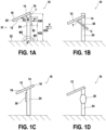
- a shade house 10 is described with reference to the Fig. 1A-1D , more particularly in view A according to a first embodiment.
- the shade house 10 includes a roof structure 12 intended to provide shade.
- the roof structure 12 can in particular be provided for supporting solar panels, for example photovoltaic panels.
- Photovoltaic panels can be fixed by means available to those skilled in the art and will therefore not be described in themselves, as well as their fixing means.
- the roof structure 12 can be solid or perforated, however, for the remainder of this presentation, it is considered that the roof structure 12, possibly equipped with photovoltaic panels or other desired equipment, presents a certain resistance to wind.
- the roof structure 12 is inclined so as to have a top part 14, which extends from a top end 16, and a bottom part 18, which extends from a bottom end 20.
- the upper part 14 is higher than the lower part 18 relative to the ground 22 in which the shade 10 is anchored.
- the upper part 14 and the lower part 18 can each represent half of the roof structure 12, or even a third, or even a quarter.
- the shade 10 For its anchoring to the ground, the shade 10 comprises a plurality of posts 24.
- the posts 24 are arranged in a single row, which is why only one of them is visible on the Fig. 1A-1D .
- several rows could be planned. Subsequently, what is described for a post 24 can be transposed to other posts.
- the vertical post 24 is anchored in the ground 22 vertically, but the post 24 could have other orientations.
- the anchor point P has been represented schematically, but those skilled in the art know that this anchor point P can be implemented using foundations, reinforcements, counterweights or other appropriate techniques.
- the post 24 supports the upper part 14 of the roof structure 12.
- the upper part 14 is fixed to the upper end of the post 24.
- the Fig. 1A-1D shows a single point of attachment, but the post 24 could be provided with one or more arms to support the upper part 14 at several points.
- the upper end 16 of the roof structure 12 is supported by the post 24.
- the lower part 18 of the roof structure 12 extends cantilever relative to the post 24.
- the lower part 18 can be free, namely on the one hand devoid of any direct support in relation to the post 24, on the other hand at a distance from the ground 22.
- the lower part 18 can be located at least two meters away, preferably at least two meters and half, from the free end of post 24. This distance corresponds to the length of the straight line segment [PQ] on view A of the Fig. 1A-1D .
- This angle T is strictly greater than 0° and less than or equal to 90°. In this case, the angle T is approximately 80°.
- the angle T can in particular be greater than 45°, preferably 60°, so that the horizontal component of the roof structure 12 is greater than the vertical component.
- the angle T may in particular be less than 87°.
- the roof structure 12 can form an angle of 0° to 30° with the horizontal.
- a part V1 of the wind V which impacts the balancing wall 30 generates an aerodynamic force (of the lift or downforce type ).
- the balancing wall 30 therefore transmits a corresponding force on the post 24.
- the post 24 being anchored in the ground, a moment M1 is created at the anchor point P which tends to make the post 24 pivot around the point anchor, to the left (or more generally in the direction of the wind V, as illustrated on the Figure 1A ).
- the shade 10 thus tends to tilt towards the left.
- a part V2 of the wind V impacts the roof structure 12.
- the roof structure 12 being inclined, the flow of the wind around the roof structure 12 generates an aerodynamic force (of the lift or downforce type), which creates, at the anchor point P, a moment M2 which tends to rotate the post 24 around the anchor point P, to the right (or more generally in the direction opposite to the wind V, as illustrated on the Figure 1A ).
- the shade 10 thus tends to tilt to the right.
- the balancing wall 30 creates, at the anchor point P, a moment M1 antagonistic to the main moment M2 which takes its origin on the roof structure 12, the resulting moment applying on the post 24 in relation to at the anchor point P is reduced.
- the moment reduction obtained by relation to the main moment M2 in the most unfavorable cases can reach several tens of percent.
- the height H30 of the balancing wall is between 2% and 100% of the height H24 of the post 24, preferably between 20% and 90%, or even between 40% and 80%.
- the heights are measured in the longitudinal direction of the post 24, which corresponds to the vertical direction when the post 24 is itself vertical.
- the distance H22 between the balancing wall 30 and the free end of the post, in this case the anchor point P, is between 0 and 98% of the height H24 of the posts.
- the balancing wall 30 extends to the maximum in the upper third, optionally in the upper quarter, of the height H24 of the post.
- the height H22 is greater than or equal to 2/3, or even 3/4 of the height H24 of the post 24.
- the balancing wall 30 can be provided at a distance from at least one of the ends of the post 24, in this case at a distance from both ends. Using the previous notations, this results in the inequality H22+H30 ⁇ H24.
- the balancing wall 30 may be provided integrally under the roof structure 12, but the upper end of the balancing wall 30 may be lower or, as illustrated, higher than the lower end 20 of the roof structure. roof 12.
- the balancing wall 30 can be arranged on one side of the post 24 opposite the lower part 18. Furthermore, the balancing wall 30 can be vertical, and more particularly parallel to the post 24 However, these characteristics can be modified, as shown in the other views of the document. Fig. 1A-1D .
- Views B to D show the shade in other embodiments.
- the elements corresponding or identical to those of the embodiment of view A will receive the same reference sign and will not be described again.
- the shade house 10 of view B differs from that of view A in that the roof structure 12 is not supported at one end of the post 24, but at an intermediate position on the post 24.
- the post 24 can therefore protrude from the roof structure 12. However, it is the upper part 14 of the roof structure 12 which is supported by the post 24.
- the balancing wall 30 is not vertical, but inclined relative to the post. More particularly, the balancing wall 30 can form, with the post, an angle U greater than or equal to 0° and less than or equal to the angle T between the roof structure 12 and the post 24.
- the balancing wall 30 can, in particular, be inclined relative to the post 24 in a direction opposite to the inclination of the roof structure 12, as illustrated in view B.
- the shade 10 of view C differs from that of view A in that the structure 12 is not supported at its upper end 16, but more generally on its upper part 14. Thus, the upper end 16 and the lower end 20 of the roof structure 12 are located on either side of the post 24.
- the balancing wall 30 is here arranged on the same side of the post 24 as the lower part 18.
- the shade 10 of view D differs from that of view A in that the balancing wall 30 is not flat.
- the balancing wall 30 is here curved, and can, to do this, have an elliptical, semi-elliptical profile, more generally curved in one direction and/or the other, or any other suitable profile. Such a profile makes it possible to precisely dimension the wind resistance of the balancing wall 30.
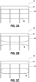
- FIGS. 2A to 2M illustrate different embodiments for the balancing wall 30, seen in direction II of the Figs. 1A-1D and for an example of a shade house 10 comprising three bays defined by a row of four posts 24. However, these examples are transposed to any other number of posts 24.
- the balancing walls 30 are identical from one bay to another. Each balancing wall 30 extends from a post 24 to an adjacent post 24. More generally, the balancing wall 30 is mechanically supported by a post 24 and extends towards another post. In this case, the balancing wall 30 is mechanically supported by the two adjacent posts 24.
- the balancing wall 30 closes 75% or less of the surface separating the post 24 which supports it from the post 24 towards which it extends. On the Figure 2A , the balancing wall 30 closes approximately a third of this surface. In other embodiments, the maximum shutter rate can be 70%, 60%, 50%, 40%, 30% or even 20%.
- the ratio of the master torque of the balancing wall 30 to the master torque of the roof structure 12 may be less than or equal to 5, preferably 4, more preferably 3. It is recalled that the master torque of a surface designates the projection of this surface on a plane perpendicular to the flow, in this case on the plane of the posts 24 which can be considered transverse to the flow of the wind in the most unfavorable scenarios.
- the aforementioned ratio may be greater than or equal to 0.01, preferably 0.05, more preferably 0.1.
- the balancing wall 30 here has a rectangular shape and is arranged approximately halfway up the posts 24.
- the variant of the Figure 2B illustrates that the balancing walls 30 may not be identical to each other. Furthermore, the shapes are not necessarily rectangular, as illustrated by the external balancing walls 30 whose edges are defined by concave curves. There Figure 2C gives the example of convex curves. In these embodiments, however, there is continuity of shape from one bay to another for the balancing walls 30.
- FIG. 2D figure illustrates balancing walls 30 whose edges in the height direction are defined by undulations, or any other periodic function.
- the balancing walls 30 nevertheless remain identical to each other and/or continuous from one bay to another.
- FIG. 2E shows an example where the balancing wall 30 is perforated, here thanks to holes 32.
- the holes 32 can be circular or not, and regularly arranged or not, it being specified, however, that a regular distribution ensures regular forces of a post 24 to the other under the effect of the wind.
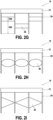
- FIG. 2F illustrates that certain bays can be provided with a balancing wall 30, while others are not.
- the figure 2G illustrates that the height H22 of the balancing walls 30 relative to the free end of the posts 24 can vary from one bay to another.
- the height H30 balancing walls can also vary, although this is not the case here.
- a one-piece balancing wall 30, for example in the shape of a parallelogram or even a diamond, can extend over two bays, while another balancing wall 30 is provided for the third bay.
- a given balancing wall 30 can be arranged at different heights from one post 24 to another, and this continuously from one bay to another, as illustrated, or not. This can make it possible to distribute the forces differently from one post 24 to another.
- the balancing wall 30 can serve incidentally as an advertising support, a barrier or even a support for equipment such as vehicle charging stations. Conversely, in a relatively high position, the balancing wall 30 can serve incidentally as a height limiter, advertising support or other, and allows passage below.
- balancing walls 30 can extend in the same bay. In this case, three balancing walls 30, separate, are provided at different heights.
- the balancing walls are identical in terms of shape and dimensions and differ here only in their location, but other variations are possible.
- FIG. 2M combines the principles of figures 2G And 2L : by arranging a variable number of balancing walls 30 in each bay and by varying the heights of these balancing walls 30, a predetermined pattern can be recreated, for example a checkerboard pattern: the walls balancing 30 are here arranged in a staggered manner. Other reasons can be considered.
- FIG. 2N illustrates the fact that instead of being arranged in a generally horizontal manner, the balancing walls 30 can be arranged in a generally vertical manner. More precisely, in this embodiment, a balancing wall 30 is fixed on a post 24 and projects beyond this post 24, on either side of this post 24. The balancing wall 30 s It therefore extends towards at least one of the neighboring posts, here both, without however reaching them.
- the shutter rate is the sum of the shutter rate linked to the balancing wall 30a fixed on the first post 24a, for its part which extends towards the second post 24b, and the shutter rate linked to the balancing wall 30b fixed on the second post 24b, for its part which extends towards the first post 24a.
- the useful parts of the balancing walls 30a, 30b are hatched on the figure 2N .
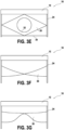
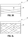
- Figures 3A to 3L illustrate, for a bay, other shapes, types and arrangement of balancing wall 30. These embodiments can be extended to several bays.
- the Figure 3A shows two triangular balancing walls 30 meeting at one of their vertices, while the other vertices serve as a fixing point on the posts 24, each balancing wall 30 having a vertex on each post 24.
- each triangular balancing wall 30 has two vertices on the same post 24.
- FIG. 3C illustrates that in addition to the rectangular, parallelogram or trapezoidal shapes seen previously, the balancing wall 30 can have a more complex polygonal shape, possibly concave.
- FIG. 3D figure shows a balancing wall 30 in the shape of a diamond.
- a cable or a support beam 34 can be provided to improve the mechanical support of the balancing wall 30 by the posts 24.
- the support cable 34 is stretched between two posts 24, here adjacent, and the balancing wall 30 is supported at least in part by this support cable 34, for example by being fixed on it, or even simply engaged on it.
- one corner of the diamond can be supported by the support cable 34, while two other corners are supported directly by the posts 24.
- a support cable 34 can be provided not only under the balancing wall 30 but also at the -on top or on one side, depending on needs. Furthermore, these characteristics can be transposed whatever the shape of the balancing wall 30.
- the method of carrying out the Figure 3E is similar to that of the 3D figure , apart from the fact that the balancing wall 30 is perforated by the presence of a drilling 32.
- the balancing wall 30 is supported relative to one of the posts 24, here the two posts 24, via one or more cables or support beams 34.
- the balancing wall 30 may not be in direct contact with the posts 24, since its fixing allows it to nevertheless be mechanically supported by at least one of the posts 24.
- a cable or a support beam 36 can mechanically connect the wall 30 to the roof structure 12, in particular to a structural element of the roof structure 12.
- Such a support mechanism offers greater design freedom for the shape of the balancing wall 30.
- the Figure 3H shows a circular balancing wall 30, but other shapes are of course possible, such as the heart shape of the Figure 3I or any form of Figure 3J .
- the number of support cables 34 can be changed, as can their location and direction. To better distribute the forces between the posts 24 and on these posts 24, it nevertheless remains desirable for the balancing wall to have its center of gravity centered in relation to the posts 24, in width and/or in height.
- FIG. 3K illustrates a grid-type pattern that can be obtained by repeating the unitary pattern of the figure 3K .
Landscapes
- Engineering & Computer Science (AREA)
- Architecture (AREA)
- Civil Engineering (AREA)
- Structural Engineering (AREA)
- Health & Medical Sciences (AREA)
- General Health & Medical Sciences (AREA)
- Toxicology (AREA)
- Life Sciences & Earth Sciences (AREA)
- Environmental Sciences (AREA)
- Photovoltaic Devices (AREA)
- Roof Covering Using Slabs Or Stiff Sheets (AREA)
- Building Awnings And Sunshades (AREA)
Priority Applications (5)
| Application Number | Priority Date | Filing Date | Title |
|---|---|---|---|
| EP23305069.9A EP4403726A1 (de) | 2023-01-20 | 2023-01-20 | Schattenspendende anlage |
| US18/237,922 US20240250635A1 (en) | 2023-01-20 | 2023-08-25 | Sunshade |
| JP2023137438A JP2024103437A (ja) | 2023-01-20 | 2023-08-25 | サンシェード |
| MX2023010242A MX2023010242A (es) | 2023-01-20 | 2023-08-31 | Toldo. |
| CN202311129442.1A CN118381429A (zh) | 2023-01-20 | 2023-09-01 | 遮阳罩 |
Applications Claiming Priority (1)
| Application Number | Priority Date | Filing Date | Title |
|---|---|---|---|
| EP23305069.9A EP4403726A1 (de) | 2023-01-20 | 2023-01-20 | Schattenspendende anlage |
Publications (1)
| Publication Number | Publication Date |
|---|---|
| EP4403726A1 true EP4403726A1 (de) | 2024-07-24 |
Family
ID=85328564
Family Applications (1)
| Application Number | Title | Priority Date | Filing Date |
|---|---|---|---|
| EP23305069.9A Pending EP4403726A1 (de) | 2023-01-20 | 2023-01-20 | Schattenspendende anlage |
Country Status (5)
| Country | Link |
|---|---|
| US (1) | US20240250635A1 (de) |
| EP (1) | EP4403726A1 (de) |
| JP (1) | JP2024103437A (de) |
| CN (1) | CN118381429A (de) |
| MX (1) | MX2023010242A (de) |
Citations (1)
| Publication number | Priority date | Publication date | Assignee | Title |
|---|---|---|---|---|
| US20180254736A1 (en) * | 2017-03-06 | 2018-09-06 | Vijay Duggal | Multi-functional solar powered barrier walls and their financing methods |
Family Cites Families (15)
| Publication number | Priority date | Publication date | Assignee | Title |
|---|---|---|---|---|
| JPH0557229U (ja) * | 1992-01-08 | 1993-07-30 | 旭硝子株式会社 | 太陽電池付き簡易車庫 |
| JPH07292913A (ja) * | 1994-04-28 | 1995-11-07 | Fujita Corp | 植栽庇 |
| JP2000145210A (ja) * | 1998-11-11 | 2000-05-26 | Sekisui House Ltd | 住宅外構を構成する架構フレーム |
| JP2004132053A (ja) * | 2002-10-10 | 2004-04-30 | Kazunobu Shibata | 日除け装置及び汎用取付け装置 |
| US8511007B2 (en) * | 2011-02-28 | 2013-08-20 | John Powers, III | Solar support structure |
| CN202081388U (zh) * | 2011-05-03 | 2011-12-21 | 新津腾中筑路机械有限公司 | 高铁挡风墙 |
| JP6043071B2 (ja) * | 2012-02-28 | 2016-12-14 | 三協立山株式会社 | 独立構造体の製造方法 |
| JP2014145186A (ja) * | 2013-01-29 | 2014-08-14 | Rui-Taka:Kk | 屋根構造体 |
| US10432132B2 (en) * | 2013-07-01 | 2019-10-01 | RBI Solar, Inc. | Solar mounting system having automatic grounding and associated methods |
| JP6476740B2 (ja) * | 2014-10-23 | 2019-03-06 | 住友電気工業株式会社 | 太陽光発電パネルおよび太陽光発電装置の製造方法 |
| KR101904280B1 (ko) * | 2018-03-14 | 2018-10-04 | 주식회사 임성 | 파고라 차양구조체 |
| CN109302131A (zh) * | 2018-11-07 | 2019-02-01 | 四川东方聚源科技有限公司 | 一种太阳能发电装置 |
| BE1028223B1 (nl) * | 2020-04-21 | 2021-11-22 | Renson Sunprotection Screens | Een ligger voor een overkapping |
| CN114006573A (zh) * | 2021-11-26 | 2022-02-01 | 辽宁省斯特贝尔电力新能源有限公司 | 光伏发电设备用自然风可自动变角装置 |
| CN113965153B (zh) * | 2021-11-26 | 2025-10-03 | 辽宁省斯特贝尔电力新能源有限公司 | 光伏发电设备用自然风可自动变角支撑钢构件 |
-
2023
- 2023-01-20 EP EP23305069.9A patent/EP4403726A1/de active Pending
- 2023-08-25 JP JP2023137438A patent/JP2024103437A/ja active Pending
- 2023-08-25 US US18/237,922 patent/US20240250635A1/en active Pending
- 2023-08-31 MX MX2023010242A patent/MX2023010242A/es unknown
- 2023-09-01 CN CN202311129442.1A patent/CN118381429A/zh active Pending
Patent Citations (1)
| Publication number | Priority date | Publication date | Assignee | Title |
|---|---|---|---|---|
| US20180254736A1 (en) * | 2017-03-06 | 2018-09-06 | Vijay Duggal | Multi-functional solar powered barrier walls and their financing methods |
Also Published As
| Publication number | Publication date |
|---|---|
| US20240250635A1 (en) | 2024-07-25 |
| MX2023010242A (es) | 2024-07-22 |
| JP2024103437A (ja) | 2024-08-01 |
| CN118381429A (zh) | 2024-07-23 |
Similar Documents
| Publication | Publication Date | Title |
|---|---|---|
| EP3593064B1 (de) | Solarmatte | |
| EP2642046B1 (de) | Einzäunungssystem | |
| WO2011023898A1 (fr) | Dispositif de fixation d'au moins un panneau sur une structure porteuse | |
| FR2949243A1 (fr) | Dispositif de type ombriere de parking photovoltaique | |
| EP4243278A1 (de) | System zum verbinden von photovoltaikpaneelen mit einer struktur mit aufgehängten kabeln | |
| WO2020012094A1 (fr) | Tour d'eolienne comprenant une structure de treillis avec des poteaux en bois et une piece de jonction metallique entre le mat de l'eolienne et lesdits poteaux | |
| EP3022362B1 (de) | Baublock und wand aus mindestens zwei solchen überlagerten blöcken | |
| WO2014016508A1 (fr) | Ancrage de centrales solaires flottantes | |
| WO2010055229A1 (fr) | Installation de couverture de protection contre le soleil | |
| EP4403726A1 (de) | Schattenspendende anlage | |
| FR2944042A1 (fr) | Installation de couverture de protection de soleil. | |
| EP3869686B1 (de) | Halterung für zweiseitige fotovoltaik-paneele | |
| CH628382A5 (en) | Construction element for the erection of walls, particularly retaining walls | |
| EP0648897B1 (de) | Schallschutzwand | |
| FR2503802A1 (fr) | Profile destine a fixer sur une paroi, et a distance de celle-ci, un revetement constitue d'une pluralite de rangees formees de plaques juxtaposees | |
| FR3112801A3 (fr) | Ombrière photovoltaïque | |
| FR3112440A1 (fr) | Support pour panneaux photovoltaïques et abri photovoltaïque correspondant | |
| FR2572745A1 (fr) | Bloc de construction d'ouvrages, de structures maritimes et/ou fluviales | |
| FR2983894B1 (fr) | Structure demontable et module de plancher prefabrique correspondant. | |
| CH694702A5 (fr) | Construction modulaire comportant au moins quatre montants verticaux et des contreventements. | |
| EP4366158B1 (de) | Bausatz zum verkleiden von wänden mit photovoltaischen paneelen | |
| EP0373085A1 (de) | Turbulenzbildung verhindernde Windschirmvorrichtung | |
| FR3155110A1 (fr) | Support au sol démontable de panneaux photovoltaïques | |
| EP4462036A1 (de) | Feste trägerstruktur für solarpaneele | |
| FR3150544A1 (fr) | ombrière adaptable à la topographie du terrain sur lequel elle doit être montée. |
Legal Events
| Date | Code | Title | Description |
|---|---|---|---|
| PUAI | Public reference made under article 153(3) epc to a published international application that has entered the european phase |
Free format text: ORIGINAL CODE: 0009012 |
|
| STAA | Information on the status of an ep patent application or granted ep patent |
Free format text: STATUS: REQUEST FOR EXAMINATION WAS MADE |
|
| 17P | Request for examination filed |
Effective date: 20230817 |
|
| AK | Designated contracting states |
Kind code of ref document: A1 Designated state(s): AL AT BE BG CH CY CZ DE DK EE ES FI FR GB GR HR HU IE IS IT LI LT LU LV MC ME MK MT NL NO PL PT RO RS SE SI SK SM TR |