EP4129753B1 - Sliding contact line detection device and sliding contact line detection system - Google Patents
Sliding contact line detection device and sliding contact line detection system Download PDFInfo
- Publication number
- EP4129753B1 EP4129753B1 EP21865530.6A EP21865530A EP4129753B1 EP 4129753 B1 EP4129753 B1 EP 4129753B1 EP 21865530 A EP21865530 A EP 21865530A EP 4129753 B1 EP4129753 B1 EP 4129753B1
- Authority
- EP
- European Patent Office
- Prior art keywords
- guide rail
- wheels
- trolley wire
- disposed
- guide
- Prior art date
- Legal status (The legal status is an assumption and is not a legal conclusion. Google has not performed a legal analysis and makes no representation as to the accuracy of the status listed.)
- Active
Links
Images



Classifications
-
- B—PERFORMING OPERATIONS; TRANSPORTING
- B60—VEHICLES IN GENERAL
- B60M—POWER SUPPLY LINES, AND DEVICES ALONG RAILS, FOR ELECTRICALLY- PROPELLED VEHICLES
- B60M1/00—Power supply lines for contact with collector on vehicle
-
- B—PERFORMING OPERATIONS; TRANSPORTING
- B60—VEHICLES IN GENERAL
- B60L—PROPULSION OF ELECTRICALLY-PROPELLED VEHICLES; SUPPLYING ELECTRIC POWER FOR AUXILIARY EQUIPMENT OF ELECTRICALLY-PROPELLED VEHICLES; ELECTRODYNAMIC BRAKE SYSTEMS FOR VEHICLES IN GENERAL; MAGNETIC SUSPENSION OR LEVITATION FOR VEHICLES; MONITORING OPERATING VARIABLES OF ELECTRICALLY-PROPELLED VEHICLES; ELECTRIC SAFETY DEVICES FOR ELECTRICALLY-PROPELLED VEHICLES
- B60L5/00—Current collectors for power supply lines of electrically-propelled vehicles
- B60L5/38—Current collectors for power supply lines of electrically-propelled vehicles for collecting current from conductor rails
-
- B—PERFORMING OPERATIONS; TRANSPORTING
- B60—VEHICLES IN GENERAL
- B60L—PROPULSION OF ELECTRICALLY-PROPELLED VEHICLES; SUPPLYING ELECTRIC POWER FOR AUXILIARY EQUIPMENT OF ELECTRICALLY-PROPELLED VEHICLES; ELECTRODYNAMIC BRAKE SYSTEMS FOR VEHICLES IN GENERAL; MAGNETIC SUSPENSION OR LEVITATION FOR VEHICLES; MONITORING OPERATING VARIABLES OF ELECTRICALLY-PROPELLED VEHICLES; ELECTRIC SAFETY DEVICES FOR ELECTRICALLY-PROPELLED VEHICLES
- B60L5/00—Current collectors for power supply lines of electrically-propelled vehicles
-
- B—PERFORMING OPERATIONS; TRANSPORTING
- B60—VEHICLES IN GENERAL
- B60L—PROPULSION OF ELECTRICALLY-PROPELLED VEHICLES; SUPPLYING ELECTRIC POWER FOR AUXILIARY EQUIPMENT OF ELECTRICALLY-PROPELLED VEHICLES; ELECTRODYNAMIC BRAKE SYSTEMS FOR VEHICLES IN GENERAL; MAGNETIC SUSPENSION OR LEVITATION FOR VEHICLES; MONITORING OPERATING VARIABLES OF ELECTRICALLY-PROPELLED VEHICLES; ELECTRIC SAFETY DEVICES FOR ELECTRICALLY-PROPELLED VEHICLES
- B60L5/00—Current collectors for power supply lines of electrically-propelled vehicles
- B60L5/04—Current collectors for power supply lines of electrically-propelled vehicles using rollers or sliding shoes in contact with trolley wire
- B60L5/045—Current collectors for power supply lines of electrically-propelled vehicles using rollers or sliding shoes in contact with trolley wire with trolley wire finders
-
- B—PERFORMING OPERATIONS; TRANSPORTING
- B60—VEHICLES IN GENERAL
- B60M—POWER SUPPLY LINES, AND DEVICES ALONG RAILS, FOR ELECTRICALLY- PROPELLED VEHICLES
- B60M1/00—Power supply lines for contact with collector on vehicle
- B60M1/12—Trolley lines; Accessories therefor
- B60M1/13—Trolley wires
-
- B—PERFORMING OPERATIONS; TRANSPORTING
- B60—VEHICLES IN GENERAL
- B60M—POWER SUPPLY LINES, AND DEVICES ALONG RAILS, FOR ELECTRICALLY- PROPELLED VEHICLES
- B60M1/00—Power supply lines for contact with collector on vehicle
- B60M1/12—Trolley lines; Accessories therefor
- B60M1/28—Manufacturing or repairing trolley lines
Definitions
- the present disclosure relates to the field of detection systems, and in particular to a trolley wire detection device and a trolley wire detection system.
- the trolley wire for power supply is installed on the frame body of work sites used for a shuttle car, etc. After installation of the trolley wire is completed, it is necessary to detect whether the installation of the trolley wire meets requirements. Whether a current collector has phenomena such as deviation and jamming when operating in the trolley wire in a plugged state is mainly detected, so as to repair the defects generated during the installation of the trolley wire in time.
- the detection in related art is mainly completed by manpower, that is, the current collector hand-held by manpower cooperates with movement of the trolley wire to detect whether there are defects in the operation process. Manual detection of the trolley wire consumes a lot of labor and time, and there are great safety hazards during detection of high-rise frame bodies.
- the document CN107433952A discloses a robot than can monitor the status of the rail transit infrastructure in general.
- Some embodiments of the present disclosure provide a trolley wire detection device, wherein a trolley wire is disposed on a guide rail and is disposed along an extending direction of the guide rail, wherein the trolley wire detection device includes:
- the power mechanism includes:
- the power mechanism further includes driven wheels, the driven wheels are disposed on the mounting seat, and the driven wheels are in contact with the guide rail, and are driven by the mounting seat to roll along the guide rail.
- the driving wheels are disposed on an outer side of the guide rail
- the driven wheels are disposed on an inner side of the guide rail
- the driven wheels and the driving wheels are configured to cooperate to clamp the guide rail.
- the guide rail includes a top wall, the driving wheels are disposed on an outer side of the top wall, and the driven wheels are disposed on an inner side of the top wall.
- the mounting seat includes:
- the connecting assembly includes:
- the power mechanism further includes guide wheels, and the guide wheels are disposed on the mounting seat, are in contact with the guide rail, and are driven by the mounting seat to roll along the guide rail.
- the guide wheels include:
- the driving wheels include a first driving wheel and a second driving wheel, two first guide wheels are disposed, and two second guide wheels are disposed; a central axis of the first driving wheel is perpendicular to and coplanar with a central axis of one of the first guide wheels; a central axis of the second driving wheel is perpendicular to and coplanar with a central axis of the other first guide wheel; and the two first guide wheels and the two second guide wheels are located in the same plane.
- the guide rail includes a top wall and a side wall connected to the top wall
- the power mechanism further includes driven wheels
- the driven wheels are disposed on the mounting seat, and the driven wheels are in contact with the guide rail, and are driven by the mounting seat to roll along the guide rail;
- the driving wheels and the driven wheels are configured to clamp the top wall of the guide rail, and the first guide wheels and the second guide wheels are configured to clamp the side wall of the guide rail.
- axes of the guide wheels are perpendicular to axes of the driving wheels.
- the engagement assembly includes magnetic assemblies which are attracted to each other and disposed on the current collector assembly and the power mechanism, or includes elastic snap-fit assemblies which are connected to each other in a snap-fit manner and disposed on the current collector assembly and the power mechanism.
- the current collector assembly includes a current collector body and a connecting member, the connecting member is connected to the current collector body, and the connecting member is also connected to the power mechanism through the engagement assembly.
- Some embodiments of the present disclosure provide a trolley wire detection system, including a trolley wire, a guide rail and the above trolley wire detection device, the trolley wire being disposed on the guide rail and disposed along an extending direction of the guide rail.
- the present disclosure at least has the following beneficial effects:
- the trolley wire detection device includes the current collector assembly, the power mechanism and the engagement assembly, the current collector assembly and the power mechanism are connected by the preset engagement force provided by the engagement assembly, before detection, the trolley wire detection device is disposed at one of end parts of the guide rail, and during detection, the current collector assembly is driven by the power mechanism to move along the trolley wire; when the trolley wire meets installation requirements, the trolley wire detection device will operate smoothly from one end of the guide rail to the other end of the guide rail; when the trolley wire has defects such as deformation and offset, the trolley wire produces a resistance to the current collector assembly, and when the resistance generated by the trolley wire to the current collector assembly is greater than the preset engagement force, the current collector assembly is disengaged from the power mechanism, which indicates that the defect exists in the installation of the trolley wire; and the position where the current collector assembly is disengaged from the power mechanism is the position of the defect in the installation of the trolley wire, and the position where the trolley wire has the installation defect can be conveniently, quickly and accurately found.
- the trolley wire detection device is convenient to operate
- An electric-driven mobile device such as a shuttle car, constantly changes the position when moving on a frame body 400. At each different position, the shuttle car (mobile device) has to obtain a power supply at any time, otherwise it cannot continue to move.
- the frame body 400 includes a guide rail 300.
- the guide rail 300 is provided with a trolley wire 200 therein.
- the trolley wire 200 is disposed along an extending direction of the guide rail 300.
- the trolley wire 200 is powered on, and a current collector that can take electricity from the trolley wire 200 is disposed on the mobile device. In this way, when the mobile device moves, the current collector operates synchronously with the mobile device, obtains the power supply from the trolley wire 200 at any time, and supplies the same to the mobile device, so that the mobile device can continue to move.
- Some embodiments of the present disclosure provide a trolley wire detection device and a trolley wire detection system, which are adopted to alleviate the problem of labor and time waste in detection of the trolley wire.
- the trolley wire detection device 100 is used to detect whether the installation of the trolley wire 200 meets the requirements.
- the frame body 400 includes the guide rail 300.
- the guide rail 300 is provided with the trolley wire 200 therein, and the trolley wire 200 is disposed along an extending direction of the guide rail 300.
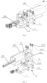
- the trolley wire detection device 100 is disposed on one of end parts of the guide rail 300 (as shown in Fig. 1 ).
- the trolley wire detection device 100 operates smoothly from one end to the other end of the guide rail 300; when the trolley wire 200 has defects such as deformation and offset, the trolley wire 200 generates a resistance to a current collector assembly 11.
- the operation of a current collector brush is no longer smooth, and has the phenomena such as jamming or deviation. Therefore, the installation defects of the trolley wire can be efficiently detected.
- the trolley wire detection device 100 includes a current collector assembly 1, a power mechanism 2 and an engagement assembly 3.
- the current collector assembly 1 is connected to the trolley wire 200 to take electricity from the trolley wire 200.
- the power mechanism 2 is slidably disposed on the guide rail 300.
- power of the power mechanism 2 includes electric power, hydraulic power or the like.
- the electric power of the power mechanism 2 is not obtained from the trolley wire.
- the engagement assembly 3 is disposed between the current collector assembly 1 and the power mechanism 2, and the engagement assembly 3 is configured to provide a preset engagement force to connect the current collector assembly 1 to the power mechanism 2.
- the power mechanism 2 is configured to drive the current collector assembly 1 to move along the trolley wire 200 after being connected to the current collector assembly 1 through the preset engagement force provided by the engagement assembly 3, and the current collector assembly 1 is configured to be disengaged from the power mechanism 2 when the resistance generated by the trolley wire 200 is greater than the preset engagement force, as shown in Fig. 9 .
- the present disclosure provides a trolley wire detection device 100, which includes the current collector assembly 1, the power mechanism 2 and the engagement assembly 3, and the current collector assembly 1 and the power mechanism 2 are connected by the preset engagement force provided by the engagement assembly 3.
- the trolley wire detection device 100 is disposed on one of end parts of the guide rail 300, and during detection, the current collector assembly 1 is driven by the power mechanism 2 to move along the trolley wire 200.
- the trolley wire detection device 100 When the trolley wire 200 meets the installation requirements, the trolley wire detection device 100 will operate smoothly from one end to the other end of the guide rail 300; when the trolley wire 200 has defects such as deformation and offset, the trolley wire 200 generates a resistance to the current collector assembly 1, and the operation of the current collector brush is no longer smooth, and has the phenomena such as jamming or deviation.
- the resistance generated by the trolley wire 200 to the current collector assembly 1 is greater than the preset engagement force, the current collector assembly 1 is disengaged from the power mechanism 2.
- the position where the current collector assembly 1 is disengaged from the power mechanism 2 is the position of the defect in installation of the trolley wire 200.
- the trolley wire detection device 100 is small in size and good in portability, and can improve the detection efficiency after the trolley wire 200 is installed, reduce labor costs, and reduce construction safety risks. Furthermore, the speed at which the power mechanism 2 drives the current collector assembly 1 to move along the trolley wire 200 is adjustable, which can highly restore actual working conditions.
- the power mechanism 2 includes a mounting seat 21 and driving wheels 22.
- the driving wheels 22 are disposed on the mounting seat 21, and the driving wheels 22 are in contact with the guide rail 300 and configured to roll along the guide rail 300 to drive the mounting seat 21 to move along the guide rail 300.
- the driving wheels 22 rotate, the mounting seat 21 drags the current collector assembly 1 to move along the guide rail 300 at a set speed.
- the driving wheel 22 includes an in-wheel motor.
- the in-wheel motor is adopted as the driving wheel.
- the driving wheel 22 includes a roller and a motor.
- the power mechanism 2 further includes driven wheels 23.
- the driven wheels 23 are disposed on the mounting seat 21.
- the driven wheels 23 are in contact with the guide rail 300 and are driven by the mounting seat 21 to roll along the guide rail 300.
- the power mechanism 2 includes the mounting seat 21, the driving wheels 22 and the driven wheels 23.
- the driving wheels 22 are disposed on the mounting seat 21 and are located on the outer side of the guide rail 300.
- the driving wheels 22 are in contact with the outer wall of the guide rail 300 and configured to roll along the guide rail 300 to drive the mounting seat 21 to move along the guide rail 300.
- the driven wheels 23 are disposed on the mounting seat 21 and located on the inner side of the guide rail 300.
- the driven wheels 23 are in contact with the inner wall of the guide rail 300, and are driven by the mounting seat 21 to roll along the guide rail 300.
- the power mechanism 2 includes a control box 25, the control box 25 is disposed on the mounting seat 21, and the control box 25 is internally provided with a battery for providing power to the driving wheels 22, a controller for controlling start, stop and rotation speeds of the driving wheels 22, and the like.
- the driving wheels 22 are disposed on the outer side of the guide rail 300
- the driven wheels 23 are disposed on the inner side of the guide rail 300
- the driven wheels 23 and the driving wheels 22 are configured to cooperate to clamp the guide rail 300.
- positions of the driven wheels 23 are aligned with positions of the driving wheels 22, and the driven wheels 23 cooperate with the driving wheels 22 to clamp the guide rail 300.
- the top wall of the guide rail 300 here is shown as the top of the guide rail 300 according to Fig. 3 to Fig. 5 .
- the top wall of the guide rail 300 may also be the side part or bottom of the guide rail 300.
- the mounting seat 21 includes a first mounting member 211, the first mounting member 211 is located on the outer side of the guide rail 300, and the driving wheels 22 are disposed on the first mounting member 211.
- the mounting seat 21 further includes a second mounting member 212, the second mounting member 212 includes a first part located on the outer side of the guide rail 300, and a second part located on the inner side of the guide rail 300, and the driven wheels 23 are disposed on the second part.
- the mounting seat 21 further includes a connecting assembly 213, the connecting assembly 213 is connected to the first mounting member 211 and the first part of the second mounting member 212, and the connecting assembly 213 is configured to adjust a gap h between the first mounting member 211 and the first part, as shown in Fig. 5 .
- the connecting assembly 213 includes screw rods 2131, first ends of the screw rods 2131 are threadedly connected to the first part of the second mounting member 212, and second ends of the screw rods 2131 penetrate the first mounting member 211. That is to say, the first mounting member 211 is provided with through holes, the screw rods 2131 penetrate the through holes, and the screw rods 2131 may move relative to the first mounting member 211.
- the connecting assembly 213 further includes springs 2132, and the springs 2132 sleeve the second ends of the screw rods 2131.
- the connecting assembly 213 further includes nuts 2133, and the nuts 2133 are threadedly connected to the second ends of the screw rods 2131 to compress the springs 2132 between the nuts 2133 and the first mounting member 211.
- the springs 2132 are compressed and extrude the first mounting member 211, so that the first mounting member 211 is deformed to approach the second mounting member 212.
- the screw rods 2131 play a guide role, and the gap h between the first mounting member 211 and the first part of the second mounting member 212 is accordingly adjusted, so that the driving wheels 22 on the first mounting member 211 and the driven wheel 23 on the second part of the second mounting member 212 can clamp the guide rail 300 to maintain a sufficient contact frictional force, and the driving wheels 22 and the driven wheels 23 can roll along the guide rail 300.
- the power mechanism 2 further includes guide wheels 24.
- the guide wheels 24 are disposed on the mounting seat 21.
- the guide wheels 24 are in contact with the guide rail 300 and are driven by the mounting seat 21 to roll along the guide rail 300.
- the guide wheels 24 may be located on the inner side or outer side of the guide rail 300.
- the guide wheels 24 are adopted to guide the operation of the entire device.
- the guide wheels 24 include first guide wheels 241, and the first guide wheels 241 are disposed on the inner side of the guide rail 300.
- the guide wheels 24 further include second guide wheels 242, and the second guide wheels 242 are disposed on the outer side of the guide rail 300; the second guide wheels 242 cooperate with the first guide wheels 241 to clamp the guide rail 300.
- positions of the second guide wheels 242 are aligned with positions of the first guide wheels 241.
- the driving wheels 22, the driven wheels 23 and the first guide wheels 241 are disposed in sequence, and aligned in position, and the driven wheels 23 are located between the driving wheels 22 and the first guide wheels 241.
- the driving wheels 22 include a first driving wheel 221 and a second driving wheel 222, the number of the first guide wheels 241 is two, and the number of the second guide wheels 242 is two; a central axis of the first driving wheel 221 is perpendicular to and coplanar with a central axis of one of the first guide wheels 241; a central axis of the second driving wheel 222 is perpendicular to and coplanar with a central axis of the other first guide wheel 241; and the two first guide wheels 241 and the two second guide wheels 242 are located in the same plane.
- the driving wheels 22 include the first driving wheel 221 and the second driving wheel 222
- the driven wheels 23 include a first driven wheel 231 and a second driven wheel 232
- the number of the first guide wheels 241 is two
- the number of the second guide wheels 242 is two.
- the central axis of the first driving wheel 221, a central axis of the first driven wheel 231 and the central axis of one of the first guide wheels 241 are coplanar
- the central axis of the second driving wheel 222, a central axis of the second driven wheel 232 and the central axis of the other first guide wheel 241 are coplanar
- the two first guide wheels 241 and the two second guide wheels 242 are located in the same plane.
- the driving wheels 22 and the driven wheels 23 are respectively in contact with two surfaces of the guide rail 300 under an action of the compression springs 2132, and clamp the guide rail 300, and the driving wheels 22 and the driven wheels 23 roll along the guide rail 300; and the two first guide wheels 241 on the inner side of the guide rail 300 and the two second guide wheels 242 on the outer side of the guide rail 300 cooperate with each other to clamp the guide rail 300.
- the guide wheels 24 are adopted to guide the operation of the entire detection device along the guide rail 300, which is beneficial for operation stability of the entire detection device.
- the guide rail 300 includes a top wall and a side wall connected to the top wall, the driving wheels 22 and the driven wheels 23 clamp the top wall of the guide rail 300, and the first guide wheels 241 and the second guide wheels 242 clamp the side wall of the guide rail 300.
- axes of the driving wheels 22 are parallel to axes of the driven wheels 23.
- Axes of the guide wheels 24 are perpendicular to the axes of the driving wheels 22.
- the driving wheels 22 and the driven wheels 23 are all located on the same side of the guide wheels 24.
- the driving wheels 22 and the driven wheels 23 are all located above the guide wheels 24, as shown in Fig. 5 .
- the engagement assembly 3 includes magnetic assemblies 31 which are attracted to each other and disposed on the current collector assembly 1 and the power mechanism 2.
- the magnetic assemblies 31 include magnets disposed on the current collector assembly 1, and also include the iron mounting seat 21 of the power mechanism 2. Further, the second mounting member 212 of the mounting seat 21 is made of metal iron.
- the current collector assembly 1 and the power mechanism 2 are connected together by an attraction force of the magnets attracting the iron. When a frictional resistance between the trolley wire 200 and the current collector assembly 1 exceeds the attraction force of the magnets, the current collector assembly 1 is disengaged from the power mechanism 2, as shown in Fig. 9 .
- the disengagement position between the current collector assembly 1 and the power mechanism 2 is the position of the defect in installation of the trolley wire.
- the magnets include rubidium magnets.
- the magnetic assemblies 31 include electromagnets disposed at the current collector assembly 1 and the power mechanism 2.
- the electromagnets can adjust a magnetic force according to different speeds to adapt to different disengagement pull forces.
- the engagement assembly 3 includes elastic snap-fit assemblies which are connected to each other in a snap-fit manner and disposed on the current collector assembly 1 and the power mechanism 2.
- the elastic snap-fit assembly includes an elastic member disposed on the current collector assembly 1 and an elastic member disposed on the power mechanism 2.
- the two elastic members are snap-fitted together through limiting tables disposed on the elastic members.
- the frictional resistance between the trolley wire 200 and the current collector assembly 1 is greater than a snap-fit force of the limiting tables on the two elastic members, the elastic members are deformed, and the current collector assembly 1 is disengaged from the power mechanism 2, referring to Fig. 9 .
- the current collector assembly 1 includes a current collector body 11 and a connecting member 12, the connecting member 12 is connected to the current collector body 11, and the connecting member 12 is connected to the power mechanism 2 through the engagement assembly 3.
- the trolley wire detection device includes two driving wheels 22, two driven wheels 23, two first guide wheels 241, and two second guide wheels 242.
- the mounting seat 21 includes the first mounting member 211 and the second mounting member 212.
- the two driving wheels 22 are disposed on the first mounting member 211 and are located on the outer side of the guide rail 300
- the two driven wheels 23 are disposed on the second mounting member 212 and are located on the inner side of the guide rail 300
- the two driving wheels 22 and the two driven wheels 23 cooperate to clamp the top wall of the guide rail 300.
- the two first guide wheels 241 are disposed on the inner side of the guide rail 300 and located below the driven wheels 23, the two second guide wheels 242 are disposed on the outer side of the guide rail 300, and the two first guide wheels 241 and the two second guide wheels 242 cooperate to clamp the side walls of the guide rail 300.
- the central axes of the driving wheels 22 are parallel to the central axes of the driven wheels 23, the central axes of the first guide wheels 241 are parallel to the central axes of the second guide wheels 242, and the central axes of the driving wheels 22 are perpendicular to the central axes of the guide wheels 24.
- the two driving wheels 22 are located in the same plane.
- the two driven wheels 23 are located in the same plane.
- the two first guide wheels 241 and the two second guide wheels 242 are located in the same plane.
- Fig. 6 shows a driving assembly, including the driving wheels 22, the first mounting member 211 and the control box 25.
- the first mounting member 211 is an L-shaped plate.
- the two driving wheels 22 are disposed on a vertical plate of the L-shaped first mounting member 211, and the control box 25 is disposed on a lateral plate of the first mounting member 211.
- the lateral plate of the first mounting member 211 is provided with the through holes for the bolts 2131 to penetrate.
- Fig. 7 shows a driven assembly, including the second mounting member 212, the first driven wheel 231, the second driven wheel 232, the two first guide wheels 241 and the two second guide wheels 242.
- the second mounting member 212 includes a first bracket 2121, a second bracket 2122 and a connecting plate 2123, the first bracket 2121 and the second bracket 2122 are disposed side by side at intervals, and the connecting plate 2123 is connected to the first bracket 2121 and the second bracket 2122.
- the structures of the first bracket 2121 and the second bracket 2122 are the same, and the first bracket 2121 is taken as an example for description.
- the first bracket 2121 includes a first mounting part and a second mounting part, and the first mounting part is provided with the first guide wheels 241 and the second guide wheels 242 at intervals.
- the first guide wheels 241 and the second guide wheels 242 are located in the same plane.
- the first mounting part is provided with a U-shaped groove, and the U-shaped groove is located between the first guide wheels 241 and the second guide wheels 242.
- First ends of the second mounting parts are connected to the first mounting parts, second ends of the second mounting parts extend upward, and the driven wheels 23 are mounted on the second mounting parts.
- the driven wheels 23 are located above the first guide wheels 241.
- the driven wheels 23 and the first guide wheels 241 are located on the inner side of the guide rail 300.
- the second guide wheels 242 are located on the outer side of the guide rail 200.
- the connecting plate 2123 is L-shaped, a vertical side of the connecting plate 2123 is connected to the first bracket 2121 and the second bracket 2122 respectively, and a lateral side of the connecting plate 2123 is located above the second guide wheels 242.
- the first ends of the screw rods 2131 are threadedly connected to the lateral side of the connecting plate 2123 (the first part of the second mounting member 212), the second ends of the screw rods 2131 penetrate the first mounting member 211, the second ends of the screw rods 2131 are provided with the springs 2132 in a sleeving manner and are threadedly connected to the nuts 2133, and the nuts 2133 compress the springs 2132 between the nuts 2133 and the first mounting member 211.
- the distance h between the lateral side of the connecting plate 2123 and the lateral plate of the first mounting member 211 is adjusted by rotating the nuts 2133, as shown in Fig. 5 .
- the current collector assembly 1 includes the current collector body 11 and the connecting member 12, the connecting member 12 is L-shaped, a first end of the connecting member 12 is connected to the current collector body 11, the middle of a second end of the connecting member 12 is provided with a positioning hole, and four magnets are disposed in a circumferential direction of the positioning hole. According to different types of trolley wires, the magnetic force or the number of the adopted magnets can be changed.
- the first bracket 2121 is made of metal iron, and the magnets on the connecting member 12 are adopted to attract the first bracket 2121 to combine the current collector assembly 1 and the power mechanism 2 together.
- the first bracket 2121 is provided with a positioning member 26, and the positioning member 26 cooperates with the positioning hole disposed in the second end of the connecting member 12 (as shown in Fig. 8 ) for positioning the connecting member 12 and the first bracket 2121.
- the positioning member 24 includes a positioning pin.
- the positioning pin is fixed on the iron first bracket 2121 and is adopted to cooperate with the positioning hole in the connecting member 12 of the current collector assembly 1 to play a positioning role, as shown in Fig. 7 and Fig. 8 .
- the trolley wire detection device further includes a sensor, the sensor is disposed at the power mechanism 2, and the sensor is adopted to collect and record the sound in a running-in process (including an abnormal sound of the current collector, the deceleration caused by local narrowing of an acceleration trolley wire slide way and other parameters), so as to process the defects of the trolley wire in time.
- a running-in process including an abnormal sound of the current collector, the deceleration caused by local narrowing of an acceleration trolley wire slide way and other parameters
- Some embodiments also provide a trolley wire detection system, including the trolley wire 200, the guide rail 300 and the above trolley wire detection device.
- the trolley wire 200 is disposed on the guide rail 300 and disposed along an extending direction of the guide rail 300.
- the guide rail 300 includes the top wall, a bottom wall, a first side wall connected to the top wall and the bottom wall, and a second side wall with one end connected to the top wall and the other end suspended in air.
- the guide rail 300 forms a cavity for accommodating the trolley wire 200 by the top wall, the bottom wall, the first side wall and the second side wall, and there is a gap between the second side wall and the bottom wall, so as to facilitate the connection between the current collector assembly 1 and the trolley wire 200, and to facilitate walking of the current collector assembly 1 along the trolley wire 200.
- the shape and structure of the guide rail 300 are not limited thereto.
- top and bottom in the top wall and the bottom wall is based on the orientation or positional relationship shown in Fig. 5 , only for the purposes of the case in describing the embodiment and simplification of its descriptions, but not indicating or implying that the specified device or element must have the specific orientation or position.
- the driving wheels 22 and the driven wheels 23 in the trolley wire detection device cooperate to clamp the top wall of the guide rail 300, and the first guide wheels 241 and the second guide wheels 242 cooperate to clamp the second side wall of the guide rail 300.
- the inner side of the guide rail 300 refers to the inside of the cavity of the guide rail
- the outer side of the guide rail 300 refers to the outer side of the cavity of the guide rail.
- the driving wheels 22 are located on the outer side of the guide rail 300
- the driven wheels 23 are located on the inner side of the guide rail 300
- the first guide wheels 241 are located on the inner side of the guide rail 300
- the second guide wheels 242 are located on the outer side of the guide rail 300.
- a length of the guide rail is 78 meters, the highest position of the guide rail is 8.5 meters, and the frame body has 16 layers in total.
- the length of the trolley wire installed on the frame body is about 30 meters to 100 meters, and the height is about 5 meters to 10 meters.
- the trolley wire detection device according to the present disclosure is adopted to detect the installation of the trolley wire, which can improve the detection efficiency after the trolley wire 200 is installed, reduce labor costs, and reduce construction safety risks.
- the speed at which the power mechanism 2 drives the current collector assembly 1 to move along the trolley wire 200 is adjustable, which can highly restore the actual working conditions.
Landscapes
- Engineering & Computer Science (AREA)
- Mechanical Engineering (AREA)
- Power Engineering (AREA)
- Transportation (AREA)
- Manufacturing & Machinery (AREA)
- Current-Collector Devices For Electrically Propelled Vehicles (AREA)
Applications Claiming Priority (2)
| Application Number | Priority Date | Filing Date | Title |
|---|---|---|---|
| CN202010936318.6A CN112297957B (zh) | 2020-09-08 | 2020-09-08 | 滑触线检测装置及滑触线检测系统 |
| PCT/CN2021/087519 WO2022052467A1 (zh) | 2020-09-08 | 2021-04-15 | 滑触线检测装置及滑触线检测系统 |
Publications (4)
| Publication Number | Publication Date |
|---|---|
| EP4129753A1 EP4129753A1 (en) | 2023-02-08 |
| EP4129753A4 EP4129753A4 (en) | 2024-05-15 |
| EP4129753B1 true EP4129753B1 (en) | 2025-06-04 |
| EP4129753C0 EP4129753C0 (en) | 2025-06-04 |
Family
ID=74484044
Family Applications (1)
| Application Number | Title | Priority Date | Filing Date |
|---|---|---|---|
| EP21865530.6A Active EP4129753B1 (en) | 2020-09-08 | 2021-04-15 | Sliding contact line detection device and sliding contact line detection system |
Country Status (5)
| Country | Link |
|---|---|
| EP (1) | EP4129753B1 (https=) |
| JP (1) | JP7578728B2 (https=) |
| CN (1) | CN112297957B (https=) |
| PL (1) | PL4129753T3 (https=) |
| WO (1) | WO2022052467A1 (https=) |
Families Citing this family (6)
| Publication number | Priority date | Publication date | Assignee | Title |
|---|---|---|---|---|
| CN112297957B (zh) * | 2020-09-08 | 2021-12-14 | 北京京东乾石科技有限公司 | 滑触线检测装置及滑触线检测系统 |
| CN113837992B (zh) * | 2021-07-14 | 2023-06-02 | 福建电子口岸股份有限公司 | 基于实例分割的碳刷盒运行检测方法、装置及可读介质 |
| CN114295904B (zh) * | 2021-11-11 | 2024-05-10 | 江苏创汇电气科技有限公司 | 一种滑触线检测装置及滑触线检测系统 |
| CN114883881B (zh) * | 2022-07-06 | 2022-09-13 | 四川东泉机械设备制造有限公司 | 一种滑触线系统 |
| CN115561067A (zh) * | 2022-07-19 | 2023-01-03 | 扬州市华宇电器设备有限公司 | 一种滑触线检测装置及滑触线检测系统 |
| CN118712945A (zh) * | 2024-08-21 | 2024-09-27 | 广州南沙海港集装箱码头有限公司 | 一种供电线巡检车、巡检系统和巡检方法 |
Family Cites Families (16)
| Publication number | Priority date | Publication date | Assignee | Title |
|---|---|---|---|---|
| JP3366912B2 (ja) * | 1991-09-27 | 2003-01-14 | 東海旅客鉄道株式会社 | トロリ線歪検出装置 |
| JPH0554058U (ja) * | 1991-12-18 | 1993-07-20 | 株式会社椿本チエイン | 高所レール点検用キャリヤ |
| JP2005269601A (ja) * | 2004-02-16 | 2005-09-29 | Ricoh Co Ltd | 原稿搬送読取装置および画像形成装置 |
| DE102014219466A1 (de) * | 2014-09-25 | 2016-03-31 | Siemens Aktiengesellschaft | Transportsystem mit einem über eine Oberleitungsanlage mit elektrischer Energie versorgbaren, nicht schienengebundenen Fahrzeug |
| CN106877230A (zh) * | 2015-12-10 | 2017-06-20 | 耘创九州智能装备有限公司 | 铁路接触网在线巡检机器人、巡检系统以及巡检方法 |
| US10464583B2 (en) * | 2016-11-28 | 2019-11-05 | Taiwan Semiconductor Manufacturing Co., Ltd. | Monitor vehicle for a rail system and method thereof |
| CN207037460U (zh) * | 2017-03-29 | 2018-02-23 | 科大智能电气技术有限公司 | 一种基于巡检机器人的巡检系统 |
| CN107433952B (zh) * | 2017-05-12 | 2018-09-14 | 北京瑞途科技有限公司 | 一种智能巡检机器人 |
| CN206914355U (zh) * | 2017-05-12 | 2018-01-23 | 北京瑞途科技有限公司 | 一种智能巡检机器人车体 |
| CN208931172U (zh) * | 2018-09-29 | 2019-06-04 | 中铁建电气化局集团南方工程有限公司 | 一种地铁隧道内接触网施工用的放线装置 |
| CN209850940U (zh) * | 2019-04-10 | 2019-12-27 | 江苏方天电力技术有限公司 | 一种轨道悬挂智能巡检机器人系统 |
| CN210201122U (zh) * | 2019-07-30 | 2020-03-27 | 洛阳前卫滑触线有限公司 | 一种滑触线集电器 |
| CN111217108B (zh) * | 2020-04-17 | 2020-07-14 | 湖南中矿金禾机器人研究院有限公司 | 一种用于极端环境皮带输送机的单轨巡检机器人系统 |
| CN212637225U (zh) * | 2020-07-09 | 2021-03-02 | 武汉黎赛科技有限责任公司 | 一种集电器跟随供电小车 |
| CN111605572B (zh) * | 2020-07-17 | 2021-07-27 | 合肥科大智能机器人技术有限公司 | 一种具有自主变轨功能的轨道式巡检机器人 |
| CN112297957B (zh) * | 2020-09-08 | 2021-12-14 | 北京京东乾石科技有限公司 | 滑触线检测装置及滑触线检测系统 |
-
2020
- 2020-09-08 CN CN202010936318.6A patent/CN112297957B/zh active Active
-
2021
- 2021-04-15 WO PCT/CN2021/087519 patent/WO2022052467A1/zh not_active Ceased
- 2021-04-15 PL PL21865530.6T patent/PL4129753T3/pl unknown
- 2021-04-15 JP JP2022575434A patent/JP7578728B2/ja active Active
- 2021-04-15 EP EP21865530.6A patent/EP4129753B1/en active Active
Also Published As
| Publication number | Publication date |
|---|---|
| US20230256830A1 (en) | 2023-08-17 |
| EP4129753A4 (en) | 2024-05-15 |
| EP4129753A1 (en) | 2023-02-08 |
| EP4129753C0 (en) | 2025-06-04 |
| JP2023539402A (ja) | 2023-09-14 |
| PL4129753T3 (pl) | 2025-09-08 |
| CN112297957B (zh) | 2021-12-14 |
| JP7578728B2 (ja) | 2024-11-06 |
| WO2022052467A1 (zh) | 2022-03-17 |
| CN112297957A (zh) | 2021-02-02 |
Similar Documents
| Publication | Publication Date | Title |
|---|---|---|
| EP4129753B1 (en) | Sliding contact line detection device and sliding contact line detection system | |
| CN107985946B (zh) | 一种双举升agv小车 | |
| CN110733564B (zh) | 一种agv小车的驱动转向装置及其工作方法 | |
| CN205396265U (zh) | 用于高空作业设备的安全防护装置及爬壁机器人 | |
| CN117144792A (zh) | 桥梁裂缝检测机器人及其工作方法 | |
| US12611936B2 (en) | Trolley wire detection device and trolley wire detection system | |
| CN221160349U (zh) | 轻便型消防控制室值班机器人 | |
| CN213381412U (zh) | 一种新能源汽车防撞梁生产用夹具 | |
| CN212637225U (zh) | 一种集电器跟随供电小车 | |
| CN107200275B (zh) | 一种汽车车身吊具 | |
| CN201686939U (zh) | 一种越障型连续移动式缆索爬行装置 | |
| CN220724733U (zh) | 一种轨枕螺栓双头扳手 | |
| CN119059473A (zh) | 一种登高车高空平台工装 | |
| CN103628768A (zh) | 一种应用于空间环境模拟器的轴向开门机构 | |
| CN201648982U (zh) | 一种小型连续移动式缆索爬行装置 | |
| CN217194015U (zh) | 一种夹具库及其夹具库切换系统 | |
| CN111908372B (zh) | 电力机车轮驱单元抱轴箱立式组装升降机 | |
| CN209890172U (zh) | 车辆动力总成的吊装装置 | |
| CN210438304U (zh) | 具有伸缩功能的单轨吊 | |
| CN203582322U (zh) | 物料转送车 | |
| JPWO2022052467A5 (https=) | ||
| CN113675029A (zh) | 一种刀闸操作装置 | |
| CN222994011U (zh) | 一种轨道交通弓网动态模拟冷滑装置 | |
| CN116618982B (zh) | 一种动车轮对轴箱拆解装置 | |
| CN206368582U (zh) | 立体车库减速装置 |
Legal Events
| Date | Code | Title | Description |
|---|---|---|---|
| STAA | Information on the status of an ep patent application or granted ep patent |
Free format text: STATUS: THE INTERNATIONAL PUBLICATION HAS BEEN MADE |
|
| PUAI | Public reference made under article 153(3) epc to a published international application that has entered the european phase |
Free format text: ORIGINAL CODE: 0009012 |
|
| STAA | Information on the status of an ep patent application or granted ep patent |
Free format text: STATUS: REQUEST FOR EXAMINATION WAS MADE |
|
| 17P | Request for examination filed |
Effective date: 20221027 |
|
| AK | Designated contracting states |
Kind code of ref document: A1 Designated state(s): AL AT BE BG CH CY CZ DE DK EE ES FI FR GB GR HR HU IE IS IT LI LT LU LV MC MK MT NL NO PL PT RO RS SE SI SK SM TR |
|
| DAV | Request for validation of the european patent (deleted) | ||
| DAX | Request for extension of the european patent (deleted) | ||
| REG | Reference to a national code |
Ref country code: DE Ref legal event code: R079 Free format text: PREVIOUS MAIN CLASS: B60M0001000000 Ref country code: DE Ref legal event code: R079 Ref document number: 602021031935 Country of ref document: DE Free format text: PREVIOUS MAIN CLASS: B60M0001000000 Ipc: B60M0001280000 |
|
| A4 | Supplementary search report drawn up and despatched |
Effective date: 20240415 |
|
| RIC1 | Information provided on ipc code assigned before grant |
Ipc: B60M 1/28 20060101AFI20240409BHEP |
|
| GRAP | Despatch of communication of intention to grant a patent |
Free format text: ORIGINAL CODE: EPIDOSNIGR1 |
|
| STAA | Information on the status of an ep patent application or granted ep patent |
Free format text: STATUS: GRANT OF PATENT IS INTENDED |
|
| INTG | Intention to grant announced |
Effective date: 20241212 |
|
| GRAS | Grant fee paid |
Free format text: ORIGINAL CODE: EPIDOSNIGR3 |
|
| GRAA | (expected) grant |
Free format text: ORIGINAL CODE: 0009210 |
|
| STAA | Information on the status of an ep patent application or granted ep patent |
Free format text: STATUS: THE PATENT HAS BEEN GRANTED |
|
| AK | Designated contracting states |
Kind code of ref document: B1 Designated state(s): AL AT BE BG CH CY CZ DE DK EE ES FI FR GB GR HR HU IE IS IT LI LT LU LV MC MK MT NL NO PL PT RO RS SE SI SK SM TR |
|
| REG | Reference to a national code |
Ref country code: GB Ref legal event code: FG4D |
|
| REG | Reference to a national code |
Ref country code: CH Ref legal event code: EP |
|
| REG | Reference to a national code |
Ref country code: IE Ref legal event code: FG4D |
|
| U01 | Request for unitary effect filed |
Effective date: 20250604 |
|
| U07 | Unitary effect registered |
Designated state(s): AT BE BG DE DK EE FI FR IT LT LU LV MT NL PT RO SE SI Effective date: 20250610 |
|
| PG25 | Lapsed in a contracting state [announced via postgrant information from national office to epo] |
Ref country code: ES Free format text: LAPSE BECAUSE OF FAILURE TO SUBMIT A TRANSLATION OF THE DESCRIPTION OR TO PAY THE FEE WITHIN THE PRESCRIBED TIME-LIMIT Effective date: 20250604 |
|
| PG25 | Lapsed in a contracting state [announced via postgrant information from national office to epo] |
Ref country code: NO Free format text: LAPSE BECAUSE OF FAILURE TO SUBMIT A TRANSLATION OF THE DESCRIPTION OR TO PAY THE FEE WITHIN THE PRESCRIBED TIME-LIMIT Effective date: 20250904 Ref country code: GR Free format text: LAPSE BECAUSE OF FAILURE TO SUBMIT A TRANSLATION OF THE DESCRIPTION OR TO PAY THE FEE WITHIN THE PRESCRIBED TIME-LIMIT Effective date: 20250905 |
|
| PG25 | Lapsed in a contracting state [announced via postgrant information from national office to epo] |
Ref country code: HR Free format text: LAPSE BECAUSE OF FAILURE TO SUBMIT A TRANSLATION OF THE DESCRIPTION OR TO PAY THE FEE WITHIN THE PRESCRIBED TIME-LIMIT Effective date: 20250604 |
|
| PG25 | Lapsed in a contracting state [announced via postgrant information from national office to epo] |
Ref country code: RS Free format text: LAPSE BECAUSE OF FAILURE TO SUBMIT A TRANSLATION OF THE DESCRIPTION OR TO PAY THE FEE WITHIN THE PRESCRIBED TIME-LIMIT Effective date: 20250904 |
|
| PG25 | Lapsed in a contracting state [announced via postgrant information from national office to epo] |
Ref country code: IS Free format text: LAPSE BECAUSE OF FAILURE TO SUBMIT A TRANSLATION OF THE DESCRIPTION OR TO PAY THE FEE WITHIN THE PRESCRIBED TIME-LIMIT Effective date: 20251004 |
|
| PG25 | Lapsed in a contracting state [announced via postgrant information from national office to epo] |
Ref country code: SM Free format text: LAPSE BECAUSE OF FAILURE TO SUBMIT A TRANSLATION OF THE DESCRIPTION OR TO PAY THE FEE WITHIN THE PRESCRIBED TIME-LIMIT Effective date: 20250604 |
|
| PG25 | Lapsed in a contracting state [announced via postgrant information from national office to epo] |
Ref country code: CZ Free format text: LAPSE BECAUSE OF FAILURE TO SUBMIT A TRANSLATION OF THE DESCRIPTION OR TO PAY THE FEE WITHIN THE PRESCRIBED TIME-LIMIT Effective date: 20250604 |
|
| PG25 | Lapsed in a contracting state [announced via postgrant information from national office to epo] |
Ref country code: SK Free format text: LAPSE BECAUSE OF FAILURE TO SUBMIT A TRANSLATION OF THE DESCRIPTION OR TO PAY THE FEE WITHIN THE PRESCRIBED TIME-LIMIT Effective date: 20250604 |
|
| PGFP | Annual fee paid to national office [announced via postgrant information from national office to epo] |
Ref country code: GB Payment date: 20260323 Year of fee payment: 6 |
|
| PLBE | No opposition filed within time limit |
Free format text: ORIGINAL CODE: 0009261 |
|
| STAA | Information on the status of an ep patent application or granted ep patent |
Free format text: STATUS: NO OPPOSITION FILED WITHIN TIME LIMIT |
|
| REG | Reference to a national code |
Ref country code: CH Ref legal event code: L10 Free format text: ST27 STATUS EVENT CODE: U-0-0-L10-L00 (AS PROVIDED BY THE NATIONAL OFFICE) Effective date: 20260416 |
|
| U20 | Renewal fee for the european patent with unitary effect paid |
Year of fee payment: 6 Effective date: 20260317 |