EP4126629B1 - Fahrwerk für ein schienenfahrzeug - Google Patents
Fahrwerk für ein schienenfahrzeug Download PDFInfo
- Publication number
- EP4126629B1 EP4126629B1 EP21728002.3A EP21728002A EP4126629B1 EP 4126629 B1 EP4126629 B1 EP 4126629B1 EP 21728002 A EP21728002 A EP 21728002A EP 4126629 B1 EP4126629 B1 EP 4126629B1
- Authority
- EP
- European Patent Office
- Prior art keywords
- wheelset
- case
- link
- connection point
- rsl12
- Prior art date
- Legal status (The legal status is an assumption and is not a legal conclusion. Google has not performed a legal analysis and makes no representation as to the accuracy of the status listed.)
- Active
Links
Images


Classifications
-
- B—PERFORMING OPERATIONS; TRANSPORTING
- B61—RAILWAYS
- B61F—RAIL VEHICLE SUSPENSIONS, e.g. UNDERFRAMES, BOGIES OR ARRANGEMENTS OF WHEEL AXLES; RAIL VEHICLES FOR USE ON TRACKS OF DIFFERENT WIDTH; PREVENTING DERAILING OF RAIL VEHICLES; WHEEL GUARDS, OBSTRUCTION REMOVERS OR THE LIKE FOR RAIL VEHICLES
- B61F5/00—Constructional details of bogies; Connections between bogies and vehicle underframes; Arrangements or devices for adjusting or allowing self-adjustment of wheel axles or bogies when rounding curves
- B61F5/38—Arrangements or devices for adjusting or allowing self- adjustment of wheel axles or bogies when rounding curves, e.g. sliding axles, swinging axles
Definitions
- the invention relates to a chassis for a rail vehicle, in particular for a locomotive.
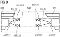
- FIG 8 shows, according to the known state of the art, a chassis with two wheel sets RS1, RS2, which are connected to a rail vehicle via a bogie frame DGR, while FIG 9 regarding FIG 8 shows a detailed view.
- a first wheelset RS1 is connected to the bogie frame DGR via two associated wheelset guides RSL11, RSL12, which are also referred to as triangular wheelset guides.
- the two wheel set guides RSL11, RSL12 are arranged along an axis which is essentially perpendicular to a direction of travel FRSF of the rail vehicle when the rail vehicle is traveling in a straight line.
- a first wheelset guide RSL11 of the first wheelset RS1 has three connection points ASP111, ASP112, ASP113.
- a first connection point ASP111 is designed as a floating bearing and connects the first wheelset guide RSL11 with the first wheelset RS1.
- a second connection point ASP112 and a third connection point ASP113 are designed as fixed bearings and connect the first axle guide RSL11 with the bogie frame DGR.
- a fixed bearing prevents all displacements and allows one or more rotations in the bearing point around a rotation axis.
- the bearing point of the fixed bearing is attached directly to the bogie frame, e.g. screwed, and supports the wishbone, which is movable relative to the bogie frame.
- a floating bearing prevents one or two displacements and allows the other displacements and one or more rotations in the bearing point.
- the bearing point can move freely relative to the bogie frame.
- a second wheelset guide RSL12 of the first wheelset RS1 has three connection points ASP121, ASP122, ASP123.
- a first connection point ASP121 is designed as a floating bearing and connects the second wheelset guide RSL12 with the first wheelset RS1.
- a second connection point ASP122 and a third connection point ASP123 are designed as fixed bearings and connect the second axle guide RSL12 with the bogie frame DGR.
- a second wheelset RS2 which is connected to the bogie frame DGR via two associated wheelset guides RSL21, RSL22, which are also referred to as triangular wheelset guides.
- the two wheel guides RSL21, RSL22 are arranged along an axis which is essentially perpendicular to the direction of travel FRSF of the rail vehicle when the rail vehicle is traveling in a straight line.
- a first wheelset guide RSL21 of the second wheelset RS2 has three connection points ASP211, ASP212, ASP213.
- a first connection point ASP211 is designed as a floating bearing and connects the first wheelset guide RSL21 with the second wheelset RS2.
- a second connection point ASP212 and a third connection point ASP213 are designed as fixed bearings and connect the first axle guide RSL21 with the bogie frame DGR.
- a second axle guide RSL22 of the second wheelset RS2 has three connection points ASP221, ASP222, ASP223.
- a first connection point ASP221 is designed as a floating bearing and connects the second wheelset guide RSL22 with the second wheelset RS2.
- a second connection point ASP222 and a third connection point ASP223 are designed as fixed bearings and connect the second axle guide RSL22 with the bogie frame DGR.
- From document DE 102013224582 A1 is a chassis for a rail vehicle in which wishbones with hydraulic bushes are used to realize dynamic running behavior.
- Wheel set guides are provided as wishbones between the axle bearing and the bogie frame.
- From document DE10 2014 214 055 A1 is a running gear for rail vehicles in which three-joints are used as wheel guides and actuators for the orientation of the axles.
- the chassis according to the invention is intended for a rail vehicle or is part of the rail vehicle.
- the running gear has a first wheelset, a bogie frame, a first wheelset guide and a second wheelset guide.
- the first wheelset is connected to the bogie frame via the two wheelset control arms.
- Each wheelset control arm is designed as a triangular control arm and has three connection points.
- a respective first connection point of the two axle guides is designed as a floating bearing and connects the associated axle guide with the first wheelset.
- a respective third connection point of the two axle guides is designed as a fixed bearing and connects the associated axle guide with the bogie frame.
- a second connection point of the first wheel set guide is connected to a first actuator, while a second connection point of the second wheel set guide is connected to a second actuator.
- the two actuators are controlled and attached in such a way that they specifically control the first wheel set when the rail vehicle is cornering. Align with a curve radius or a track curve to be traveled.
- a fixed bearing prevents all displacement and allows one or more rotations in the bearing point around a rotation axis.
- the bearing point of the fixed bearing is attached directly to the bogie frame, e.g. screwed, and supports the wishbone, which is movable relative to the bogie frame.
- a floating bearing prevents one or two displacements and allows the other displacements and one or more rotations in the bearing point.
- the bearing point is freely movable relative to the bogie frame.
- the chassis has a second wheelset.
- the chassis has a first wheelset guide and a second wheelset guide for the second wheelset.
- the second wheelset is connected to the bogie frame via the two wheelset guides.
- the second connection point of the first wheel set guide is connected via the first actuator to a fixed bearing which is attached to the bogie frame. Accordingly, the second connection point of the second wheel set guide is connected via the second actuator to a fixed bearing which is attached to the bogie frame.
- the actuators are controlled and fastened in such a way that they are set equally when the rail vehicle travels straight ahead.
- the actuators are designed as electric servo motors or as mechanical actuators.
- the mechanical actuators are designed as pneumatic or hydraulic actuators or as mixed forms.
- the present invention achieves a minimization of wear when cornering with little additional effort.
- the present invention achieves optimized driving stability even at high speeds.
- the present invention achieves an optimized steering of the wheel sets so that optimal rail contact is achieved in a track curve.
- the present invention thus realizes an increased traction performance of the rail vehicle.
- FIG 1 and FIG 2 show an embodiment of a chassis FW1 according to the invention.
- the FW1 chassis has a first wheel set RS1 and a second wheel set RS2, which are connected to a rail vehicle via a bogie frame DGR.
- the first wheelset RS1 is connected to the bogie frame DGR via two associated wheelset guides RSL11, RSL12, which are also referred to as triangular wheelset guides.
- the two wheel set guides RSL11, RSL12 of the first wheel set RS1 are arranged along an axis, which in a straight Travel of the rail vehicle is essentially perpendicular to a travel direction FRSF of the rail vehicle.
- a first wheelset guide RSL11 of the first wheelset RS1 has three connection points ASP111, ASP112, ASP113.
- a first connection point ASP111 of the first wheel set guide RSL11 is designed as a floating bearing and connects the first wheel set guide RSL11 with the first wheel set RS1.
- a second connection point ASP112 of the first wheel set guide RSL11 is connected via a first actuator AKT11 to a second connection point ASP212 of a first wheel set guide RSL21, wherein this first wheel set guide RSL21 is assigned to the second wheel set RS2.
- a third connection point ASP113 of the first axle guide RSL11 of the first wheelset RS1 is designed as a fixed bearing and connects the first axle guide RSL11 with the bogie frame DGR.
- the second wheelset RS2 has a similar structure - it is connected to the bogie frame DGR via two associated wheelset guides RSL21, RSL22, which are also called triangular wheelset guides.
- the two wheel set guides RSL21, RSL22 of the second wheel set RS2 are arranged along an axis which is essentially perpendicular to a direction of travel FRSF of the rail vehicle when the rail vehicle is traveling in a straight line.
- a first wheelset guide RSL21 of the second wheelset RS2 has three connection points ASP211, ASP212, ASP213.
- a first connection point ASP211 of the first wheelset guide RSL21 is designed as a floating bearing and connects the first wheelset guide RSL21 with the second wheelset RS2.
- a second connection point ASP212 of the first wheel set guide RSL21 is connected via the first actuator AKT11 to the second connection point ASP112 of the first wheel set guide RSL11, whereby this first wheel set guide RSL11 is assigned to the first wheel set RS1.
- a third connection point ASP213 of the first axle guide RSL21 of the second wheelset RS2 is designed as a fixed bearing and connects the first axle guide RSL21 with the bogie frame DGR.
- a second wheelset guide RSL12 of the first wheelset RS1 has three connection points ASP121, ASP122, ASP123.
- a first connection point ASP121 of the second wheel set guide RSL12 is designed as a floating bearing and connects the second wheel set guide RSL12 with the first wheel set RS1.
- a second connection point ASP122 of the second wheel set guide RSL12 is connected via a second actuator AKT12 to a second connection point ASP222 of a second wheel set guide RSL22, whereby this second wheel set guide RSL22 is assigned to the second wheel set RS2.
- a third connection point ASP123 of the second wheel set guide RSL12 of the first wheel set RS1 is designed as a fixed bearing and connects the second axle guide RSL12 with the bogie frame DGR.
- the second wheelset RS2 has a similar structure - it is connected to the bogie frame DGR via two associated wheelset guides RSL21, RSL22, which are also called triangular wheelset guides.
- the two wheel set guides RSL21, RSL22 of the second wheel set RS2 are arranged along an axis which is essentially perpendicular to a direction of travel FRSF of the rail vehicle when the rail vehicle is traveling in a straight line.
- a second axle guide RSL22 of the second wheelset RS2 has three connection points ASP221, ASP222, ASP223.
- a first connection point ASP221 of the second wheel set guide RSL22 is designed as a floating bearing and connects the second wheel set guide RSL22 with the second wheel set RS2.
- a second connection point ASP222 of the second wheel set guide RSL22 is connected via the second actuator AKT12 to the second connection point ASP122 of the second wheel set guide RSL12, whereby this second wheel set guide RSL12 is assigned to the first wheel set RS1.
- a third connection point ASP223 of the second axle guide RSL22 of the second wheelset RS2 is designed as a fixed bearing and connects the second axle guide RSL22 with the bogie frame DGR.
- the two actuators AKT11 and AKT12 are used as actuators for the two wheel sets RS1, RS2 of the chassis FW1.
- the two actuators AKT11 and AKT12 are therefore functionally coupled with each other. They are controlled or activated as described below.
- the two actuators AKT11 and AKT12 are controlled in such a way that the two wheel sets RS1, RS2 are rotated. This is done with the aim of aligning the two wheel sets RS1, RS2 in an optimized manner to the curved path to be traveled or to its curve radius. This minimizes wear when cornering.
- the two actuators AKT11 and AKT12 are controlled in the same way when the rail vehicle travels straight ahead. This means that the two wheel sets RS1, RS2 are aligned for straight ahead travel and are blocked or locked via the two actuators AKT11 and AKT12, which take on a fixed bearing function with regard to their connection points.
- FIG 2 also shows two linear guides LF111, LF112, which are coupled to the actuator AKT11.
- FIG 3 shows with reference to the figures FIG1, FIG2 the position of the two actuators AKT11, AKT12 when the rail vehicle travels straight ahead on straight tracks GL.
- the two actuators AKT11 and AKT12 are set and controlled in the same way.
- the two wheel sets are therefore aligned in the same way for straight-ahead travel and are not twisted.
- FIG 4 shows with reference to the figures FIG 1, FIG 2 the position of the two actuators AKT11, AKT12 when the rail vehicle is cornering on GL tracks that are laid along a curve with a curve radius KR.
- the two actuators AKT11 and AKT12 are set differently from each other, so that a targeted alignment or adjustment of the two wheel sets RS1, RS2 to the curve radius KR or to the track curve is carried out.
- the two actuators AKT11, AKT12 are preferably designed as electric servomotors or as mechanical actuators based on pneumatic or hydraulic actuating principles. Suitable mixed forms of actuators are also conceivable.
- FIG 5 shows a second, unclaimed design of the chassis FW2, while FIG 6 a detail from FIG 5 shows.
- the FW2 chassis has two wheel sets RS1, RS2, which are connected to a rail vehicle via a bogie frame DGR.
- a first wheelset RS1 is connected to the bogie frame DGR via two associated wheelset guides RSL11, RSL12, which are also referred to as triangular wheelset guides.
- the two wheel set guides RSL11, RSL12 are arranged along an axis which is essentially perpendicular to a direction of travel FRSF of the rail vehicle when the rail vehicle is traveling in a straight line.
- a first wheelset guide RSL11 of the first wheelset RS1 has three connection points ASP111, ASP112, ASP113.
- a first connection point ASP111 is designed as a floating bearing and connects the first wheelset guide RSL11 with the first wheelset RS1.
- a second connection point ASP112 is connected via a first actuator AKT21 to a fixed bearing which is attached to the bogie frame DGR.
- a third connection point ASP113 is designed as a fixed bearing and connects the first axle guide RSL11 with the bogie frame DGR.
- a second wheelset guide RSL12 of the first wheelset RS1 has three connection points ASP121, ASP122, ASP123.
- a first connection point ASP121 is designed as a floating bearing and connects the second wheelset guide RSL12 with the first wheelset RS1.
- a second connection point ASP122 is connected via a second actuator AKT22 to a fixed bearing which is attached to the bogie frame DGR.
- a third connection point ASP123 is designed as a fixed bearing and connects the second axle guide RSL12 with the bogie frame DGR.
- a second wheelset RS2 which is connected to the bogie frame DGR via two associated wheelset guides RSL21, RSL22, which are also referred to as triangular wheelset guides.
- the two wheel guides RSL21, RSL22 are arranged along an axis which is essentially perpendicular to the direction of travel FRSF of the rail vehicle when the rail vehicle is traveling in a straight line.
- a first wheelset guide RSL21 of the second wheelset RS2 has three connection points ASP211, ASP212, ASP213.
- a first connection point ASP211 is designed as a floating bearing and connects the first wheelset guide RSL21 with the second wheelset RS2.
- a second connection point ASP212 is connected via a third actuator AKT23 to a fixed bearing which is attached to the bogie frame DGR.
- a third connection point ASP213 is designed as a fixed bearing and connects the first axle guide RSL21 with the bogie frame DGR.
- a second axle guide RSL22 of the second wheelset RS2 has three connection points ASP221, ASP222, ASP223.
- a first connection point ASP221 is designed as a floating bearing and connects the second wheelset guide RSL22 with the second wheelset RS2.
- a second connection point ASP222 is connected via a fourth actuator AKT24 to a fixed bearing which is attached to the bogie frame DGR.
- a third connection point ASP223 is designed as a fixed bearing and connects the second axle guide RSL22 with the bogie frame DGR.
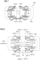
- FIG 7 shows with reference to FIGS. 5 and 6 the chassis according to the invention when cornering.
- the four actuators AKT21 to AKT24 would be set or controlled in the same way.
- the two wheel sets RS1, RS2 would then be aligned in the same way for straight ahead travel and would not be rotated.
- the four actuators AKT21 to AKT24 are set in such a way that the two wheel sets RS1, RS2 are specifically aligned or adjusted to a curve radius or a track curve.
- the actuators AKT21 to AKT24 are preferably designed as electric servomotors or as mechanical actuators based on pneumatic or hydraulic actuating principles. Suitable mixed forms of actuators are also conceivable.
Landscapes
- Engineering & Computer Science (AREA)
- Mechanical Engineering (AREA)
- Platform Screen Doors And Railroad Systems (AREA)
Description
- Die Erfindung betriff ein Fahrwerk für ein Schienenfahrzeug, insbesondere für eine Lokomotive.
- Bei Fahrwerken für Schienenfahrzeuge besteht ein grundsätzlicher Zielkonflikt zwischen einem dynamischen Laufverhalten bei Bogenfahrt einerseits und einer Fahrstabilität bei Geradeausfahrt mit hoher Geschwindigkeit andererseits.
-
FIG 8 zeigt gemäß dem bekannten Stand der Technik ein Fahrwerk mit zwei Radsätzen RS1, RS2, die über einen Drehgestellrahmen DGR mit einem Schienenfahrzeug verbunden sind, währendFIG 9 mit Bezug aufFIG 8 eine Detailansicht zeigt. - Ein erster Radsatz RS1 ist über zwei ihm zugeordnete Radsatzlenker RSL11, RSL12, die auch als Dreieckradsatzlenker bezeichnet werden, mit dem Drehgestellrahmen DGR verbunden.
- Dabei sind die beiden Radsatzlenker RSL11, RSL12 längs einer Achse angeordnet, die bei einer geraden Fahrt des Schienenfahrzeugs im Wesentlichen senkrecht zu einer Fahrtrichtung FRSF des Schienenfahrzeugs steht.
- Ein erster Radsatzlenker RSL11 des ersten Radsatzes RS1 weist drei Anschlusspunkte ASP111, ASP112, ASP113 auf.
- Ein erster Anschlusspunkt ASP111 ist dabei als Loslager ausgebildet und verbindet den ersten Radsatzlenker RSL11 mit dem ersten Radsatz RS1.
- Ein zweiter Anschlusspunkt ASP112 und ein dritter Anschlusspunkt ASP113 sind als Festlager ausgebildet und verbinden den ersten Radsatzlenker RSL11 mit dem Drehgestellrahmen DGR.
- Ein Festlager unterbindet alle Verschiebungen und ermöglicht eine oder mehrere Verdrehungen im Lagerpunkt um eine Rotationsachse.
- Hier ist der Lagerpunkt des Festlagers direkt am Drehgestellrahmen befestigt, z.B. geschraubt, und stützt den Dreieckslenker, der gegenüber dem Drehgestellrahmen beweglich ist.
- Ein Loslager unterbindet eine oder zwei Verschiebungen und lässt die anderen Verschiebungen und eine oder mehrere Verdrehungen im Lagerpunkt zu. Hier ist der Lagerpunkt gegenüber dem Drehgestellrahmen frei beweglich.
- Ein zweiter Radsatzlenker RSL12 des ersten Radsatzes RS1 weist drei Anschlusspunkte ASP121, ASP122, ASP123 auf.
- Ein erster Anschlusspunkt ASP121 ist dabei als Loslager ausgebildet und verbindet den zweiten Radsatzlenker RSL12 mit dem ersten Radsatz RS1.
- Ein zweiter Anschlusspunkt ASP122 und ein dritter Anschlusspunkt ASP123 sind als Festlager ausgebildet und verbinden den zweiten Radsatzlenker RSL12 mit dem Drehgestellrahmen DGR.
- Der gleiche Aufbau gilt für einen zweiten Radsatz RS2, der über zwei ihm zugeordnete Radsatzlenker RSL21, RSL22, die auch als Dreieckradsatzlenker bezeichnet werden, mit dem Drehgestellrahmen DGR verbunden ist.
- Dabei sind die beiden Radsatzlenker RSL21, RSL22 längs einer Achse angeordnet, die bei einer geraden Fahrt des Schienenfahrzeugs im Wesentlichen senkrecht zur Fahrtrichtung FRSF des Schienenfahrzeugs steht.
- Ein erster Radsatzlenker RSL21 des zweiten Radsatzes RS2 weist drei Anschlusspunkte ASP211, ASP212, ASP213 auf.
- Ein erster Anschlusspunkt ASP211 ist dabei als Loslager ausgebildet und verbindet den ersten Radsatzlenker RSL21 mit dem zweiten Radsatz RS2.
- Ein zweiter Anschlusspunkt ASP212 und ein dritter Anschlusspunkt ASP213 sind als Festlager ausgebildet und verbinden den ersten Radsatzlenker RSL21 mit dem Drehgestellrahmen DGR.
- Ein zweiter Radsatzlenker RSL22 des zweiten Radsatzes RS2 weist drei Anschlusspunkte ASP221, ASP222, ASP223 auf.
- Ein erster Anschlusspunkt ASP221 ist dabei als Loslager ausgebildet und verbindet den zweiten Radsatzlenker RSL22 mit dem zweiten Radsatz RS2.
- Ein zweiter Anschlusspunkt ASP222 und ein dritter Anschlusspunkt ASP223 sind als Festlager ausgebildet und verbinden den zweiten Radsatzlenker RSL22 mit dem Drehgestellrahmen DGR.
- Nachteilig an dieser Lösung ist, dass bei einer Fahrt des Schienenfahrzeugs in einem Gleisbogen aufgrund der festen Radstellung sowohl an den Radsätzen als auch am Gleis ein hoher Verschleiß verursacht wird.
- Aus Dokument
DE 102013224582 A1 ist ein Fahrwerk für ein Schienenfahrzeug bekannt, bei dem Dreieckslenker mit Hydraulikbuschen verwendet werden, um ein dynamisches Laufverhalten zu realisieren. - Aus Dokument
DE 4424884 A1 ist ein Laufwerk für Schienenfahrzeuge bekannt. Dabei werden Radsatzlenker als Dreieckslenker zwischen Achslager und Drehgestellrahmen vorgesehen. - Aus Dokument
DE10 2014 214 055 A1 ist ein Laufwerk für Schienenfahrzeuge bekannt, bei welchem Dreigelenke als Radsatzlenker sowie Aktuatoren zur Orientierung der Achsen verwendet werden. - Es ist daher Aufgabe der vorliegenden Erfindung, ein Fahrgestell der vorstehend beschriebenen Art anzugeben, bei dem bei geringem Verschleiß ein dynamisches Laufverhalten bei Bogenfahrten des Schienenfahrzeugs einerseits und eine Fahrstabilität bei Geradeausfahrt des Schienenfahrzeugs mit hoher Geschwindigkeit andererseits realisiert ist.
- Diese Aufgabe wird durch die Merkmale des Patenanspruchs 1 gelöst. Vorteilhafte Weiterbildungen sind in den abhängigen Ansprüchen angegeben.
- Das erfindungsgemäße Fahrwerk ist für ein Schienenfahrzeug bestimmt bzw. ist Teil des Schienenfahrzeugs.
- Das Fahrwerk weist einen ersten Radsatz, einen Drehgestellrahmen, einen ersten Radsatzlenker und einen zweiten Radsatzlenker auf.
- Der erste Radsatz ist über die beiden Radsatzlenker mit dem Drehgestellrahmen verbunden. Jeder Radsatzlenker ist als Dreieckslenker ausgebildet weist jeweils drei Anschlusspunkte auf.
- Ein jeweiliger erster Anschlusspunkt der beiden Radsatzlenker ist als Loslager ausgebildet und verbindet den zugehörigen Radsatzlenker mit dem ersten Radsatz. Ein jeweiliger dritter Anschlusspunkt der beiden Radsatzlenker ist als Festlager ausgebildet und verbindet den zugehörigen Radsatzlenker mit dem Drehgestellrahmen.
- Erfindungsgemäß ist ein zweiter Anschlusspunkt des ersten Radsatzlenkers mit einem ersten Aktuator verbunden, während ein zweiter Anschlusspunkt des zweiten Radsatzlenkers mit einem zweiten Aktuator verbunden ist. Die beiden Aktuatoren sind derart angesteuert und befestigt, dass sie bei einer Kurvenfahrt des Schienenfahrzeugs den ersten Radsatz gezielt auf einen Kurvenradius bzw. auf einen zu befahrenden Gleisbogen ausrichten.
- Ein Festlager unterbindet alle Verschiebungen und ermöglicht eine oder mehrere Verdrehungen im Lagerpunkt um eine Rotationsachse. Bevorzugt ist hier der Lagerpunkt des Festlagers direkt am Drehgestellrahmen befestigt, z.B. geschraubt, und stützt den Dreieckslenker, der gegenüber dem Drehgestellrahmen beweglich ist.
- Ein Loslager unterbindet eine oder zwei Verschiebungen und lässt die anderen Verschiebungen und eine oder mehrere Verdrehungen im Lagerpunkt zu. Bevorzugt ist hier der Lagerpunkt gegenüber dem Drehgestellrahmen frei beweglich.
- Erfindungsgemäß weist das Fahrwerk einen zweiten Radsatz auf. Das Fahrwerk weist für den zweiten Radsatz einen ersten Radsatzlenker und einen zweiten Radsatzlenker auf. Der zweite Radsatz ist über die beiden Radsatzlenker mit dem Drehgestellrahmen verbunden.
- Jeder dieser Radsatzlenker ist als Dreieckslenker ausgebildet und weist jeweils drei Anschlusspunkte auf:
- ein jeweiliger erster Anschlusspunkt dieser beiden Radsatzlenker ist als Loslager ausgebildet und verbindet den zugehörigen Radsatzlenker mit dem zweiten Radsatz,
- ein jeweiliger dritter Anschlusspunkt dieser beiden Radsatzlenker ist als Festlager ausgebildet und verbindet den zugehörigen Radsatzlenker mit dem Drehgestellrahmen,
- ein zweiter Anschlusspunkt dieses ersten Radsatzlenkers ist über den ersten Aktuator mit dem zweiten Anschlusspunkt des ersten Radsatzlenkers des ersten Radsatzes verbunden, während
- ein zweiter Anschlusspunkt des zweiten Radsatzlenkers des zweiten Radsatzes ist über den zweiten Aktuator mit dem zweiten Anschlusspunkt des zweiten Radsatzlenkers des ersten Radsatzes verbunden.
- In einer nicht beanspruchten alternativen Weiterbildung des Fahrwerks ist der zweite Anschlusspunkt des ersten Radsatzlenkers über den ersten Aktuator mit einem Festlager verbunden, das am Drehgestellrahmen befestigt ist. Entsprechend ist der zweite Anschlusspunkt des zweiten Radsatzlenkers über den zweiten Aktuator mit einem Festlager verbunden, das am Drehgestellrahmen befestigt ist.
- In einer vorteilhaften Weiterbildung sind die Aktuatoren derart angesteuert und befestigt, dass sie bei einer Geradeausfahrt des Schienenfahrzeugs gleich eingestellt sind.
- In einer vorteilhaften Weiterbildung sind die Aktuatoren als elektrische Stellmotoren oder als mechanische Aktuatoren ausgebildet.
- In einer vorteilhaften Weiterbildung sind die mechanischen Aktuatoren als pneumatische oder als hydraulische Aktuatoren oder als Mischformen ausgebildet.
- Durch die vorliegende Erfindung wird bei geringem Zusatzaufwand eine Verschleißminimierung bei Kurvenfahrten erreicht.
- Durch die vorliegende Erfindung wird auch bei hohen Geschwindigkeiten eine optimierte Fahrstabilität erreicht.
- Durch die vorliegende Erfindung wird ein optimiertes Einlenken der Radsätze erreicht, so dass ein optimaler Schienenkontakt in einem Gleisbogen erzielt wird.
- Durch die vorliegende Erfindung wird somit eine erhöhte Traktionsleistung des Schienenfahrtzeugs realisiert.
- Nachfolgend wird die vorliegende Erfindung beispielhaft anhand einer Zeichnung näher erläutert. Dabei zeigt:
- FIG 1
- eine Ausgestaltung des erfindungsgemäßen Fahrwerks,
- FIG 2
- ein Detail aus
FIG 1 , - FIG 3
- mit Bezug auf
FIG 1 und FIG 2 das erfindungsgemäße Fahrwerk bei Geradeausfahrt, - FIG 4
- mit Bezug auf
FIG 1 und FIG 2 das erfindungsgemäße Fahrwerk bei Kurvenfahrt, - FIG 5
- eine weitere, nicht beanspruchte Ausgestaltung des Fahrwerks,
- FIG 6
- ein Detail aus
FIG 5 , - FIG 7
- mit Bezug auf
FIG 5 und FIG 6 das Fahrwerk bei Kurvenfahrt, - FIG 8
- und
FIG 9 das in der Einleitung beschriebene Fahrwerk gemäß dem Stand der Technik. -
FIG 1 und FIG 2 zeigen eine Ausgestaltung eines erfindungsgemäßen Fahrwerks FW1. - Das Fahrwerk FW1 weist einen ersten Radsatz RS1 und einen zweiten Radsatz RS2 auf, die über einen Drehgestellrahmen DGR mit einem Schienenfahrzeug verbunden sind.
- Der erste Radsatz RS1 ist über zwei ihm zugeordnete Radsatzlenker RSL11, RSL12, die auch als Dreieckradsatzlenker bezeichnet werden, mit dem Drehgestellrahmen DGR verbunden.
- Dabei sind die beiden Radsatzlenker RSL11, RSL12 des ersten Radsatzes RS1 längs einer Achse angeordnet, die bei einer geraden Fahrt des Schienenfahrzeugs im Wesentlichen senkrecht zu einer Fahrtrichtung FRSF des Schienenfahrzeugs steht.
- Ein erster Radsatzlenker RSL11 des ersten Radsatzes RS1 weist drei Anschlusspunkte ASP111, ASP112, ASP113 auf.
- Ein erster Anschlusspunkt ASP111 des ersten Radsatzlenkers RSL11 ist dabei als Loslager ausgebildet und verbindet den ersten Radsatzlenker RSL11 mit dem ersten Radsatz RS1.
- Ein zweiter Anschlusspunkt ASP112 des ersten Radsatzlenkers RSL11 ist über einen ersten Aktuator AKT11 mit einem zweiten Anschlusspunkt ASP212 eines ersten Radsatzlenkers RSL21 verbunden, wobei dieser erste Radsatzlenker RSL21 dem zweiten Radsatz RS2 zugeordnet ist.
- Ein dritter Anschlusspunkt ASP113 des ersten Radsatzlenkers RSL11 des ersten Radsatzes RS1 ist als Festlager ausgebildet und verbindet den ersten Radsatzlenker RSL11 mit dem Drehgestellrahmen DGR.
- Der zweite Radsatz RS2 ist vergleichbar aufgebaut - er ist über zwei ihm zugeordnete Radsatzlenker RSL21, RSL22, die auch als Dreieckradsatzlenker bezeichnet werden, mit dem Drehgestellrahmen DGR verbunden.
- Dabei sind die beiden Radsatzlenker RSL21, RSL22 des zweiten Radsatzes RS2 längs einer Achse angeordnet, die bei einer geraden Fahrt des Schienenfahrzeugs im Wesentlichen senkrecht zu einer Fahrtrichtung FRSF des Schienenfahrzeugs steht.
- Ein erster Radsatzlenker RSL21 des zweiten Radsatzes RS2 weist drei Anschlusspunkte ASP211, ASP212, ASP213 auf.
- Ein erster Anschlusspunkt ASP211 des ersten Radsatzlenkers RSL21 ist dabei als Loslager ausgebildet und verbindet den ersten Radsatzlenker RSL21 mit dem zweiten Radsatz RS2.
- Ein zweiter Anschlusspunkt ASP212 des ersten Radsatzlenkers RSL21 ist über den ersten Aktuator AKT11 mit dem zweiten Anschlusspunkt ASP112 des ersten Radsatzlenkers RSL11 verbunden, wobei dieser erste Radsatzlenker RSL11 dem ersten Radsatz RS1 zugeordnet ist.
- Ein dritter Anschlusspunkt ASP213 des ersten Radsatzlenkers RSL21 des zweiten Radsatzes RS2 ist als Festlager ausgebildet und verbindet den ersten Radsatzlenker RSL21 mit dem Drehgestellrahmen DGR.
- Der oben beschriebene Aufbau setzt sich in Bezug zur Fahrtrichtung FRSF des Schienenfahrzeugs spiegelsymmetrisch fort, so dass gilt:
Ein zweiter Radsatzlenker RSL12 des ersten Radsatzes RS1 weist drei Anschlusspunkte ASP121, ASP122, ASP123 auf. - Ein erster Anschlusspunkt ASP121 des zweiten Radsatzlenkers RSL12 ist dabei als Loslager ausgebildet und verbindet den zweiten Radsatzlenker RSL12 mit dem ersten Radsatz RS1.
- Ein zweiter Anschlusspunkt ASP122 des zweiten Radsatzlenkers RSL12 ist über einen zweiten Aktuator AKT12 mit einem zweiten Anschlusspunkt ASP222 eines zweiten Radsatzlenkers RSL22 verbunden, wobei dieser zweite Radsatzlenker RSL22 dem zweiten Radsatz RS2 zugeordnet ist.
- Ein dritter Anschlusspunkt ASP123 des zweiten Radsatzlenkers RSL12 des ersten Radsatzes RS1 ist als Festlager ausgebildet und verbindet den zweiten Radsatzlenker RSL12 mit dem Drehgestellrahmen DGR.
- Der zweite Radsatz RS2 ist vergleichbar aufgebaut - er ist über zwei ihm zugeordnete Radsatzlenker RSL21, RSL22, die auch als Dreieckradsatzlenker bezeichnet werden, mit dem Drehgestellrahmen DGR verbunden.
- Dabei sind die beiden Radsatzlenker RSL21, RSL22 des zweiten Radsatzes RS2 längs einer Achse angeordnet, die bei einer geraden Fahrt des Schienenfahrzeugs im Wesentlichen senkrecht zu einer Fahrtrichtung FRSF des Schienenfahrzeugs steht.
- Ein zweiter Radsatzlenker RSL22 des zweiten Radsatzes RS2 weist drei Anschlusspunkte ASP221, ASP222, ASP223 auf.
- Ein erster Anschlusspunkt ASP221 des zweiten Radsatzlenkers RSL22 ist dabei als Loslager ausgebildet und verbindet den zweiten Radsatzlenker RSL22 mit dem zweiten Radsatz RS2.
- Ein zweiter Anschlusspunkt ASP222 des zweiten Radsatzlenkers RSL22 ist über den zweiten Aktuator AKT12 mit dem zweiten Anschlusspunkt ASP122 des zweiten Radsatzlenkers RSL12 verbunden, wobei dieser zweite Radsatzlenker RSL12 dem ersten Radsatz RS1 zugeordnet ist.
- Ein dritter Anschlusspunkt ASP223 des zweiten Radsatzlenkers RSL22 des zweiten Radsatzes RS2 ist als Festlager ausgebildet und verbindet den zweiten Radsatzlenker RSL22 mit dem Drehgestellrahmen DGR.
- Die beiden Aktuatoren AKT11 und AKT12 werden als Stellglieder der beiden Radsätze RS1, RS2 des Fahrwerks FW1 verwendet.
- Die beiden Aktuatoren AKT11 und AKT12 sind daher funktionell miteinander gekoppelt. Sie werden wie nachfolgend beschrieben gesteuert bzw. angesteuert.
- Die beiden Aktuatoren AKT11 und AKT12 werden bei einer Kurvenfahrt des Schienenfahrzeugs derart angesteuert, dass die beiden Radsätze RS1, RS2 verdreht werden. Dies erfolgt mit dem Ziel, die beiden Radsätze RS1, RS2 auf die zu befahrende Kurvenbahn bzw. auf deren Kurvenradius optimiert auszurichten. Dadurch wird bei Kurvenfahrten eine Verschleißminimierung erreicht.
- Die beiden Aktuatoren AKT11 und AKT12 werden bei einer Geradeausfahrt des Schienenfahrzeugs gleich angesteuert. Dadurch sind die beiden Radsätze RS1, RS2 für eine Geradeausfahrt ausgerichtet und über die beiden Aktuatoren AKT11 und AKT12, die mit Bezug auf Ihre Anschlusspunkte eine Festlager-Funktionalität übernehmen, gesperrt bzw. verriegelt.
-
FIG 2 zeigt außerdem zwei Linearführungen LF111, LF112, die mit dem Aktuator AKT11 gekoppelt sind. - Derartige Linearführungen sind in einer bevorzugten Ausgestaltung - auch wenn diese nicht im Detail in den nachfolgenden Figuren gezeigt sind - Bestandteil der beschriebenen Lösungen bzw. Bestandteil der bei der vorliegenden Erfindung verwendeten Aktuatoren.
-
FIG 3 zeigt mit Bezug auf die FigurenFIG1, FIG 2 die Stellung der beiden Aktuatoren AKT11, AKT12 bei einer Geradeausfahrt des Schienenfahrzeugs auf geraden Gleisen GL. - Hier sind die beiden Aktuatoren AKT11 und AKT12 gleich eingestellt bzw. angesteuert.
- Die beiden Radsätze sind also für die Geradeausfahrt gleich ausgerichtet bzw. nicht verdreht angeordnet.
-
FIG 4 zeigt mit Bezug auf die FigurenFIG 1, FIG 2 die Stellung der beiden Aktuatoren AKT11, AKT12 bei einer Kurvenfahrt des Schienenfahrzeugs auf Gleisen GL, die längs einer Kurve mit einem Kurvenradius KR verlegt sind. - Hier sind die beiden Aktuatoren AKT11 und AKT12 abweichend voneinander eingestellt, so dass eine gezielte Ausrichtung bzw. Einstellung der beiden Radsätze RS1, RS2 auf den Kurvenradius KR bzw. auf den Gleisbogen erfolgt.
- Die beiden Aktuatoren AKT11, AKT12 sind bevorzugt als elektrische Stellmotoren oder als mechanische Aktuatoren ausgebildet, die auf pneumatischen oder hydraulischen Stellprinzipien beruhen. Ebenso sind geeignete Mischformen von Aktuatoren denkbar.
-
FIG 5 zeigt eine zweite, nicht beanspruchte Ausgestaltung des Fahrwerks FW2, währendFIG 6 ein Detail ausFIG 5 zeigt. - Das Fahrwerk FW2 weist zwei Radsätzen RS1, RS2 auf, die über einen Drehgestellrahmen DGR mit einem Schienenfahrzeug verbunden sind.
- Ein erster Radsatz RS1 ist über zwei ihm zugeordnete Radsatzlenker RSL11, RSL12, die auch als Dreieckradsatzlenker bezeichnet werden, mit dem Drehgestellrahmen DGR verbunden.
- Dabei sind die beiden Radsatzlenker RSL11, RSL12 längs einer Achse angeordnet, die bei einer geraden Fahrt des Schienenfahrzeugs im Wesentlichen senkrecht zu einer Fahrtrichtung FRSF des Schienenfahrzeugs steht.
- Ein erster Radsatzlenker RSL11 des ersten Radsatzes RS1 weist drei Anschlusspunkte ASP111, ASP112, ASP113 auf.
- Ein erster Anschlusspunkt ASP111 ist dabei als Loslager ausgebildet und verbindet den ersten Radsatzlenker RSL11 mit dem ersten Radsatz RS1.
- Ein zweiter Anschlusspunkt ASP112 ist über einen ersten Aktuator AKT21 mit einem Festlager verbunden, das am Drehgestellrahmen DGR befestigt ist.
- Ein dritter Anschlusspunkt ASP113 sind als Festlager ausgebildet und verbindet den ersten Radsatzlenker RSL11 mit dem Drehgestellrahmen DGR.
- Ein zweiter Radsatzlenker RSL12 des ersten Radsatzes RS1 weist drei Anschlusspunkte ASP121, ASP122, ASP123 auf.
- Ein erster Anschlusspunkt ASP121 ist dabei als Loslager ausgebildet und verbindet den zweiten Radsatzlenker RSL12 mit dem ersten Radsatz RS1.
- Ein zweiter Anschlusspunkt ASP122 und ist über einen zweiten Aktuator AKT22 mit einem Festlager verbunden, das am Drehgestellrahmen DGR befestigt ist.
- Ein dritter Anschlusspunkt ASP123 ist als Festlager ausgebildet und verbindet den zweiten Radsatzlenker RSL12 mit dem Drehgestellrahmen DGR.
- Der gleiche Aufbau gilt für einen zweiten Radsatz RS2, der über zwei ihm zugeordnete Radsatzlenker RSL21, RSL22, die auch als Dreieckradsatzlenker bezeichnet werden, mit dem Drehgestellrahmen DGR verbunden ist.
- Dabei sind die beiden Radsatzlenker RSL21, RSL22 längs einer Achse angeordnet, die bei einer geraden Fahrt des Schienenfahrzeugs im Wesentlichen senkrecht zur Fahrtrichtung FRSF des Schienenfahrzeugs steht.
- Ein erster Radsatzlenker RSL21 des zweiten Radsatzes RS2 weist drei Anschlusspunkte ASP211, ASP212, ASP213 auf.
- Ein erster Anschlusspunkt ASP211 ist dabei als Loslager ausgebildet und verbindet den ersten Radsatzlenker RSL21 mit dem zweiten Radsatz RS2.
- Ein zweiter Anschlusspunkt ASP212 ist über einen dritten Aktuator AKT23 mit einem Festlager verbunden, das am Drehgestellrahmen DGR befestigt ist.
- Ein dritter Anschlusspunkt ASP213 ist als Festlager ausgebildet und verbindet den ersten Radsatzlenker RSL21 mit dem Drehgestellrahmen DGR.
- Ein zweiter Radsatzlenker RSL22 des zweiten Radsatzes RS2 weist drei Anschlusspunkte ASP221, ASP222, ASP223 auf.
- Ein erster Anschlusspunkt ASP221 ist dabei als Loslager ausgebildet und verbindet den zweiten Radsatzlenker RSL22 mit dem zweiten Radsatz RS2.
- Ein zweiter Anschlusspunkt ASP222 ist über einen vierten Aktuator AKT24 mit einem Festlager verbunden, das am Drehgestellrahmen DGR befestigt ist.
- Ein dritter Anschlusspunkt ASP223 ist als Festlager ausgebildet und verbindet den zweiten Radsatzlenker RSL22 mit dem Drehgestellrahmen DGR.
-
FIG 7 zeigt mit Bezug aufFIG 5 und FIG 6 das erfindungsgemäße Fahrwerk bei Kurvenfahrt. - Bei einer Geradeausfahrt des Schienenfahrzeugs wären die vier Aktuatoren AKT21 bis AKT24 gleich eingestellt bzw. angesteuert. Die beiden Radsätze RS1, RS2 wären dann für die Geradeausfahrt gleich ausgerichtet bzw. nicht verdreht angeordnet.
- Bei der hier gezeigten Kurvenfahrt des Schienenfahrzeugs sind die vier Aktuatoren AKT21 bis AKT24 derart eingestellt, dass eine gezielte Ausrichtung bzw. Einstellung der beiden Radsätze RS1, RS2 auf einen Kurvenradius bzw. auf einen Gleisbogen erfolgt.
- Die Aktuatoren AKT21 bis AKT24 sind bevorzugt als elektrische Stellmotoren oder als mechanische Aktuatoren ausgebildet, die auf pneumatischen oder hydraulischen Stellprinzipien beruhen. Ebenso sind geeignete Mischformen von Aktuatoren denkbar.
Claims (5)
- Fahrwerk (FW1) für ein Schienenfahrzeug,- mit einem ersten Radsatz (RS1), mit einem Drehgestellrahmen (DGR), mit einem ersten Radsatzlenker (RSL11) und mit einem zweiten Radsatzlenker (RSL12),- bei dem der erste Radsatz (RS1) über die beiden Radsatzlenker (RSL11, RSL12) mit dem Drehgestellrahmen (DGR) verbunden ist,- bei dem jeder Radsatzlenker (RSL11, RSL12) als Dreieckslenker ausgebildet ist und jeweils drei Anschlusspunkte (ASP111-ASP113, ASP121-ASP123) aufweist,- bei dem ein jeweiliger erster Anschlusspunkt (ASP111, ASP121) der beiden Radsatzlenker (RSL11, RSL12) als Loslager ausgebildet ist und den zugehörigen Radsatzlenker (RSL11, RSL12) mit dem ersten Radsatz (RS1) verbindet,- bei dem ein jeweiliger dritter Anschlusspunkt (ASP113, ASP123) der beiden Radsatzlenker (RLS11, RSL12) als Festlager ausgebildet ist und den zugehörigen Radsatzlenker (RSL11, RSL12) mit dem Drehgestellrahmen (DGR) verbindet,- bei dem ein zweiter Anschlusspunkt (ASP112) des ersten Radsatzlenkers (RSL11) mit einem ersten Aktuator (AKT11) verbunden ist,- bei dem ein zweiter Anschlusspunkt (ASP112) des zweiten Radsatzlenkers (RSL12) mit einem zweiten Aktuator (AKT12) verbunden ist,- bei dem die beiden Aktuatoren (AKT11, AKT12) derart angesteuert und befestigt sind, dass sie bei einer Kurvenfahrt des Schienenfahrzeugs den ersten Radsatz (RS1) gezielt auf einen Kurvenradius bzw. auf einen zu befahrenden Gleisbogen ausrichten,- bei dem das Fahrwerk (FW1) einen zweiten Radsatz (RS2) aufweist,- bei dem das Fahrwerk für den zweiten Radsatz (RS2) einen ersten Radsatzlenker (RSL21) und einen zweiten Radsatzlenker (RSL22) aufweist, und bei dem der zweite Radsatz (RS2) über die beiden Radsatzlenker (RSL21, RSL22) mit dem Drehgestellrahmen (DGR) verbunden ist,- bei dem beim zweiten Radsatz (RS2) jeder Radsatzlenker (RSL21, RSL22) als Dreieckslenker ausgebildet ist und jeweils drei Anschlusspunkte (ASP211-ASP213, ASP221-ASP223) aufweist,- bei dem beim zweiten Radsatz (RS2) ein jeweiliger erster Anschlusspunkt (ASP211, ASP221) der beiden Radsatzlenker (RLS21, RSL22) als Loslager ausgebildet ist und den zugehörigen Radsatzlenker (RSL21, RSL22) mit dem zweiten Radsatz (RS2) verbindet,- bei dem beim zweiten Radsatz (RS2) ein jeweiliger dritter Anschlusspunkt (ASP213, ASP223) der beiden Radsatzlenker (RLS21, RSL22) als Festlager ausgebildet ist und den zugehörigen Radsatzlenker (RSL21, RSL22) mit dem Drehgestellrahmen (DGR) verbindet,- bei dem beim zweiten Radsatz (RS2) ein zweiter Anschlusspunkt (ASP212) des ersten Radsatzlenkers (RSL21) über den ersten Aktuator (AKT11) mit dem zweiten Anschlusspunkt (ASP112) des ersten Radsatzlenkers (RSL11) des ersten Radsatzes (RS1) verbunden ist, und- bei dem beim zweiten Radsatz (RS2) ein zweiter Anschlusspunkt (ASP222) des zweiten Radsatzlenkers (RSL22) über den zweiten Aktuator (AKT12) mit dem zweiten Anschlusspunkt (ASP122) des zweiten Radsatzlenkers (RSL12) des ersten Radsatzes (RS1) verbunden ist.
- Fahrwerk nach einem der vorhergehenden Ansprüche, bei dem die Aktuatoren derart angesteuert und befestigt sind, dass sie bei einer Geradeausfahrt des Schienenfahrzeugs gleich eingestellt sind.
- Fahrwerk nach einem der vorhergehenden Ansprüche, bei dem die Aktuatoren als elektrische Stellmotoren oder als mechanische Aktuatoren ausgebildet sind.
- Fahrwerk nach einem der vorhergehenden Ansprüche, bei dem die mechanischen Aktuatoren als pneumatische oder als hydraulische Aktuatoren ausgebildet sind.
- Schienenfahrzeug mit einem Fahrwerk, das nach einem der vorhergehenden Ansprüche ausgebildet ist.
Applications Claiming Priority (2)
| Application Number | Priority Date | Filing Date | Title |
|---|---|---|---|
| DE102020206252.8A DE102020206252A1 (de) | 2020-05-18 | 2020-05-18 | Fahrwerk für ein Schienenfahrzeug |
| PCT/EP2021/061792 WO2021233680A1 (de) | 2020-05-18 | 2021-05-05 | Fahrwerk für ein schienenfahrzeug |
Publications (2)
| Publication Number | Publication Date |
|---|---|
| EP4126629A1 EP4126629A1 (de) | 2023-02-08 |
| EP4126629B1 true EP4126629B1 (de) | 2024-06-26 |
Family
ID=76138043
Family Applications (1)
| Application Number | Title | Priority Date | Filing Date |
|---|---|---|---|
| EP21728002.3A Active EP4126629B1 (de) | 2020-05-18 | 2021-05-05 | Fahrwerk für ein schienenfahrzeug |
Country Status (6)
| Country | Link |
|---|---|
| EP (1) | EP4126629B1 (de) |
| CN (1) | CN115667047B (de) |
| DE (1) | DE102020206252A1 (de) |
| ES (1) | ES2986982T3 (de) |
| PL (1) | PL4126629T3 (de) |
| WO (1) | WO2021233680A1 (de) |
Citations (1)
| Publication number | Priority date | Publication date | Assignee | Title |
|---|---|---|---|---|
| EP3129272B1 (de) * | 2014-07-18 | 2018-12-12 | Siemens Mobility GmbH | Fahrwerk für ein schienenfahrzeug |
Family Cites Families (11)
| Publication number | Priority date | Publication date | Assignee | Title |
|---|---|---|---|---|
| DE3331559A1 (de) * | 1983-09-01 | 1985-03-28 | Thyssen Industrie Ag, 4300 Essen | Achssteuerung fuer schienenfahrzeuge |
| DE4424884A1 (de) * | 1994-07-14 | 1996-01-18 | Siemens Schienenfahrzeugtech | Laufwerk für Schienenfahrzeuge |
| DE10137443A1 (de) * | 2001-07-27 | 2003-03-06 | Bombardier Transp Gmbh | Verfahren und Vorrichtung zur aktiven Radialsteuerung von Radpaaren oder Radsätzen von Fahrzeugen |
| DE102004007376A1 (de) | 2004-02-16 | 2005-09-01 | Ropers, Diedrich | Laufwerk für Schienenfahrzeuge mit verstellbaren Radsätzen |
| DE102006025773A1 (de) * | 2006-05-31 | 2007-12-06 | Bombardier Transportation Gmbh | Verfahren zur Regelung eines aktiven Fahrwerks eines Schienenfahrzeugs |
| DE102007025163A1 (de) * | 2007-05-29 | 2008-12-04 | Bombardier Transportation Gmbh | Schienenfahrzeug mit einstufiger Federung |
| EP2371656A1 (de) * | 2010-03-29 | 2011-10-05 | Siemens AG Österreich | Schienenfahrzeug mit variabler Achsgeometrie |
| FR2970457B1 (fr) * | 2011-01-17 | 2013-02-15 | Alstom Transport Sa | Bogie de vehicule ferroviaire suspendu |
| EP2762377B1 (de) * | 2013-01-30 | 2019-07-31 | Bombardier Transportation GmbH | Fahrwerk mit gesteuerter Radeinheit |
| DE102013224582A1 (de) * | 2013-11-29 | 2015-06-03 | Siemens Aktiengesellschaft | Fahrwerk für ein Schienenfahrzeug |
| CN108657213B (zh) * | 2017-03-30 | 2020-04-24 | 比亚迪股份有限公司 | 转向架及具有其的轨道车辆和轨道交通系统 |
-
2020
- 2020-05-18 DE DE102020206252.8A patent/DE102020206252A1/de not_active Ceased
-
2021
- 2021-05-05 ES ES21728002T patent/ES2986982T3/es active Active
- 2021-05-05 EP EP21728002.3A patent/EP4126629B1/de active Active
- 2021-05-05 PL PL21728002.3T patent/PL4126629T3/pl unknown
- 2021-05-05 CN CN202180036138.5A patent/CN115667047B/zh active Active
- 2021-05-05 WO PCT/EP2021/061792 patent/WO2021233680A1/de not_active Ceased
Patent Citations (1)
| Publication number | Priority date | Publication date | Assignee | Title |
|---|---|---|---|---|
| EP3129272B1 (de) * | 2014-07-18 | 2018-12-12 | Siemens Mobility GmbH | Fahrwerk für ein schienenfahrzeug |
Also Published As
| Publication number | Publication date |
|---|---|
| CN115667047B (zh) | 2025-05-09 |
| ES2986982T3 (es) | 2024-11-13 |
| PL4126629T3 (pl) | 2024-10-28 |
| DE102020206252A1 (de) | 2021-11-18 |
| EP4126629A1 (de) | 2023-02-08 |
| CN115667047A (zh) | 2023-01-31 |
| WO2021233680A1 (de) | 2021-11-25 |
Similar Documents
| Publication | Publication Date | Title |
|---|---|---|
| EP2552761B1 (de) | Schienenfahrzeug mit variabler achsgeometrie | |
| EP1412240B1 (de) | Verfahren und vorrichtung zur aktiven radialsteuerung von radpaaren oder radsätzen von fahrzeugen | |
| AT407865B (de) | Laufwerk für ein schienenfahrzeug mit drei in einem rahmen hintereinander angeordneten radsätzen | |
| DE102021202609A1 (de) | Aktuator einer Steer-by-wire-Lenkung sowie Steer-by-wire-Lenkung | |
| EP0908368B1 (de) | Neigevorrichtung | |
| WO2008006329A2 (de) | Schienenfahrzeug | |
| EP0770533B1 (de) | Einrichtung zur Führung von Fahrzeugen | |
| EP4126629A1 (de) | Fahrwerk für ein schienenfahrzeug | |
| EP2158114B1 (de) | Schienenfahrzeug mit einstufiger federung | |
| DE4109356C2 (de) | Verfahren zur Spurführung der Laufräder eines schienengebundenen Fahrzeuges | |
| DE102021131350A1 (de) | Verstellantrieb für eine verstellbare Lenksäuleneinheit | |
| DE10329689A1 (de) | Achsaufhängung für Kraftfahrzeuge | |
| EP0794101B1 (de) | Schienenfahrzeug mit vier oder sechs in radialer Stellung steuerbaren Radsätzen | |
| DE102005002882B4 (de) | Fahrgestell für ein auf einer Bahn spurgeführtes Spielfahrzeug | |
| DE4414293C1 (de) | Fahrwerk für Schienenfahrzeuge | |
| DE102020134069B4 (de) | Schienenfahrzeug für eine Einschienenbahn | |
| DE19515587C1 (de) | Fahrwerk für Schienenfahrzeuge | |
| AT525689B1 (de) | Schienenfahrzeug | |
| EP0679561A1 (de) | Selbstlenkendes, dreiachsiges Laufgestell mit Lenkbalken | |
| EP4588750A1 (de) | Querführungsanordnung | |
| AT401034B (de) | Fahrwerk, insbesondere drehgestell, für ein schienenfahrzeug | |
| DE102021128531A1 (de) | Lenkung für einen Kraftwagen, insbesondere einen Personenkraftwagen, sowie Kraftwagen | |
| EP0999111A1 (de) | Begrenzungsanschlag mit einem mindestens bei Bogenstellung in Querrichtung eines Schienenfahrzeuges wirksamen Queranschlagsabschnitt | |
| DE102021125226A1 (de) | Radaufhängung mit bogenförmiger Lenkführung | |
| DE4415293A1 (de) | Laufwerk mit Winkelhebeln für ein Schienenfahrzeug |
Legal Events
| Date | Code | Title | Description |
|---|---|---|---|
| STAA | Information on the status of an ep patent application or granted ep patent |
Free format text: STATUS: UNKNOWN |
|
| STAA | Information on the status of an ep patent application or granted ep patent |
Free format text: STATUS: THE INTERNATIONAL PUBLICATION HAS BEEN MADE |
|
| PUAI | Public reference made under article 153(3) epc to a published international application that has entered the european phase |
Free format text: ORIGINAL CODE: 0009012 |
|
| STAA | Information on the status of an ep patent application or granted ep patent |
Free format text: STATUS: REQUEST FOR EXAMINATION WAS MADE |
|
| 17P | Request for examination filed |
Effective date: 20221031 |
|
| AK | Designated contracting states |
Kind code of ref document: A1 Designated state(s): AL AT BE BG CH CY CZ DE DK EE ES FI FR GB GR HR HU IE IS IT LI LT LU LV MC MK MT NL NO PL PT RO RS SE SI SK SM TR |
|
| DAV | Request for validation of the european patent (deleted) | ||
| DAX | Request for extension of the european patent (deleted) | ||
| GRAP | Despatch of communication of intention to grant a patent |
Free format text: ORIGINAL CODE: EPIDOSNIGR1 |
|
| STAA | Information on the status of an ep patent application or granted ep patent |
Free format text: STATUS: GRANT OF PATENT IS INTENDED |
|
| INTG | Intention to grant announced |
Effective date: 20230918 |
|
| GRAJ | Information related to disapproval of communication of intention to grant by the applicant or resumption of examination proceedings by the epo deleted |
Free format text: ORIGINAL CODE: EPIDOSDIGR1 |
|
| STAA | Information on the status of an ep patent application or granted ep patent |
Free format text: STATUS: REQUEST FOR EXAMINATION WAS MADE |
|
| INTC | Intention to grant announced (deleted) | ||
| GRAP | Despatch of communication of intention to grant a patent |
Free format text: ORIGINAL CODE: EPIDOSNIGR1 |
|
| STAA | Information on the status of an ep patent application or granted ep patent |
Free format text: STATUS: GRANT OF PATENT IS INTENDED |
|
| INTG | Intention to grant announced |
Effective date: 20240105 |
|
| GRAS | Grant fee paid |
Free format text: ORIGINAL CODE: EPIDOSNIGR3 |
|
| GRAA | (expected) grant |
Free format text: ORIGINAL CODE: 0009210 |
|
| STAA | Information on the status of an ep patent application or granted ep patent |
Free format text: STATUS: THE PATENT HAS BEEN GRANTED |
|
| AK | Designated contracting states |
Kind code of ref document: B1 Designated state(s): AL AT BE BG CH CY CZ DE DK EE ES FI FR GB GR HR HU IE IS IT LI LT LU LV MC MK MT NL NO PL PT RO RS SE SI SK SM TR |
|
| REG | Reference to a national code |
Ref country code: GB Ref legal event code: FG4D Free format text: NOT ENGLISH |
|
| REG | Reference to a national code |
Ref country code: CH Ref legal event code: EP |
|
| REG | Reference to a national code |
Ref country code: DE Ref legal event code: R096 Ref document number: 502021004129 Country of ref document: DE |
|
| PG25 | Lapsed in a contracting state [announced via postgrant information from national office to epo] |
Ref country code: BG Free format text: LAPSE BECAUSE OF FAILURE TO SUBMIT A TRANSLATION OF THE DESCRIPTION OR TO PAY THE FEE WITHIN THE PRESCRIBED TIME-LIMIT Effective date: 20240626 |
|
| PG25 | Lapsed in a contracting state [announced via postgrant information from national office to epo] |
Ref country code: HR Free format text: LAPSE BECAUSE OF FAILURE TO SUBMIT A TRANSLATION OF THE DESCRIPTION OR TO PAY THE FEE WITHIN THE PRESCRIBED TIME-LIMIT Effective date: 20240626 Ref country code: FI Free format text: LAPSE BECAUSE OF FAILURE TO SUBMIT A TRANSLATION OF THE DESCRIPTION OR TO PAY THE FEE WITHIN THE PRESCRIBED TIME-LIMIT Effective date: 20240626 |
|
| REG | Reference to a national code |
Ref country code: LT Ref legal event code: MG9D |
|
| PG25 | Lapsed in a contracting state [announced via postgrant information from national office to epo] |
Ref country code: GR Free format text: LAPSE BECAUSE OF FAILURE TO SUBMIT A TRANSLATION OF THE DESCRIPTION OR TO PAY THE FEE WITHIN THE PRESCRIBED TIME-LIMIT Effective date: 20240927 |
|
| PG25 | Lapsed in a contracting state [announced via postgrant information from national office to epo] |
Ref country code: LV Free format text: LAPSE BECAUSE OF FAILURE TO SUBMIT A TRANSLATION OF THE DESCRIPTION OR TO PAY THE FEE WITHIN THE PRESCRIBED TIME-LIMIT Effective date: 20240626 |
|
| REG | Reference to a national code |
Ref country code: NL Ref legal event code: MP Effective date: 20240626 |
|
| PG25 | Lapsed in a contracting state [announced via postgrant information from national office to epo] |
Ref country code: NO Free format text: LAPSE BECAUSE OF FAILURE TO SUBMIT A TRANSLATION OF THE DESCRIPTION OR TO PAY THE FEE WITHIN THE PRESCRIBED TIME-LIMIT Effective date: 20240926 Ref country code: LV Free format text: LAPSE BECAUSE OF FAILURE TO SUBMIT A TRANSLATION OF THE DESCRIPTION OR TO PAY THE FEE WITHIN THE PRESCRIBED TIME-LIMIT Effective date: 20240626 Ref country code: HR Free format text: LAPSE BECAUSE OF FAILURE TO SUBMIT A TRANSLATION OF THE DESCRIPTION OR TO PAY THE FEE WITHIN THE PRESCRIBED TIME-LIMIT Effective date: 20240626 Ref country code: GR Free format text: LAPSE BECAUSE OF FAILURE TO SUBMIT A TRANSLATION OF THE DESCRIPTION OR TO PAY THE FEE WITHIN THE PRESCRIBED TIME-LIMIT Effective date: 20240927 Ref country code: FI Free format text: LAPSE BECAUSE OF FAILURE TO SUBMIT A TRANSLATION OF THE DESCRIPTION OR TO PAY THE FEE WITHIN THE PRESCRIBED TIME-LIMIT Effective date: 20240626 Ref country code: BG Free format text: LAPSE BECAUSE OF FAILURE TO SUBMIT A TRANSLATION OF THE DESCRIPTION OR TO PAY THE FEE WITHIN THE PRESCRIBED TIME-LIMIT Effective date: 20240626 Ref country code: RS Free format text: LAPSE BECAUSE OF FAILURE TO SUBMIT A TRANSLATION OF THE DESCRIPTION OR TO PAY THE FEE WITHIN THE PRESCRIBED TIME-LIMIT Effective date: 20240926 |
|
| REG | Reference to a national code |
Ref country code: ES Ref legal event code: FG2A Ref document number: 2986982 Country of ref document: ES Kind code of ref document: T3 Effective date: 20241113 |
|
| PG25 | Lapsed in a contracting state [announced via postgrant information from national office to epo] |
Ref country code: NL Free format text: LAPSE BECAUSE OF FAILURE TO SUBMIT A TRANSLATION OF THE DESCRIPTION OR TO PAY THE FEE WITHIN THE PRESCRIBED TIME-LIMIT Effective date: 20240626 |
|
| PG25 | Lapsed in a contracting state [announced via postgrant information from national office to epo] |
Ref country code: NL Free format text: LAPSE BECAUSE OF FAILURE TO SUBMIT A TRANSLATION OF THE DESCRIPTION OR TO PAY THE FEE WITHIN THE PRESCRIBED TIME-LIMIT Effective date: 20240626 |
|
| PG25 | Lapsed in a contracting state [announced via postgrant information from national office to epo] |
Ref country code: PT Free format text: LAPSE BECAUSE OF FAILURE TO SUBMIT A TRANSLATION OF THE DESCRIPTION OR TO PAY THE FEE WITHIN THE PRESCRIBED TIME-LIMIT Effective date: 20241028 |
|
| PG25 | Lapsed in a contracting state [announced via postgrant information from national office to epo] |
Ref country code: PT Free format text: LAPSE BECAUSE OF FAILURE TO SUBMIT A TRANSLATION OF THE DESCRIPTION OR TO PAY THE FEE WITHIN THE PRESCRIBED TIME-LIMIT Effective date: 20241028 |
|
| PG25 | Lapsed in a contracting state [announced via postgrant information from national office to epo] |
Ref country code: EE Free format text: LAPSE BECAUSE OF FAILURE TO SUBMIT A TRANSLATION OF THE DESCRIPTION OR TO PAY THE FEE WITHIN THE PRESCRIBED TIME-LIMIT Effective date: 20240626 |
|
| PG25 | Lapsed in a contracting state [announced via postgrant information from national office to epo] |
Ref country code: IS Free format text: LAPSE BECAUSE OF FAILURE TO SUBMIT A TRANSLATION OF THE DESCRIPTION OR TO PAY THE FEE WITHIN THE PRESCRIBED TIME-LIMIT Effective date: 20241026 |
|
| PG25 | Lapsed in a contracting state [announced via postgrant information from national office to epo] |
Ref country code: RO Free format text: LAPSE BECAUSE OF FAILURE TO SUBMIT A TRANSLATION OF THE DESCRIPTION OR TO PAY THE FEE WITHIN THE PRESCRIBED TIME-LIMIT Effective date: 20240626 Ref country code: SK Free format text: LAPSE BECAUSE OF FAILURE TO SUBMIT A TRANSLATION OF THE DESCRIPTION OR TO PAY THE FEE WITHIN THE PRESCRIBED TIME-LIMIT Effective date: 20240626 |
|
| PG25 | Lapsed in a contracting state [announced via postgrant information from national office to epo] |
Ref country code: SM Free format text: LAPSE BECAUSE OF FAILURE TO SUBMIT A TRANSLATION OF THE DESCRIPTION OR TO PAY THE FEE WITHIN THE PRESCRIBED TIME-LIMIT Effective date: 20240626 |
|
| PG25 | Lapsed in a contracting state [announced via postgrant information from national office to epo] |
Ref country code: SM Free format text: LAPSE BECAUSE OF FAILURE TO SUBMIT A TRANSLATION OF THE DESCRIPTION OR TO PAY THE FEE WITHIN THE PRESCRIBED TIME-LIMIT Effective date: 20240626 Ref country code: SK Free format text: LAPSE BECAUSE OF FAILURE TO SUBMIT A TRANSLATION OF THE DESCRIPTION OR TO PAY THE FEE WITHIN THE PRESCRIBED TIME-LIMIT Effective date: 20240626 Ref country code: RO Free format text: LAPSE BECAUSE OF FAILURE TO SUBMIT A TRANSLATION OF THE DESCRIPTION OR TO PAY THE FEE WITHIN THE PRESCRIBED TIME-LIMIT Effective date: 20240626 Ref country code: IS Free format text: LAPSE BECAUSE OF FAILURE TO SUBMIT A TRANSLATION OF THE DESCRIPTION OR TO PAY THE FEE WITHIN THE PRESCRIBED TIME-LIMIT Effective date: 20241026 Ref country code: EE Free format text: LAPSE BECAUSE OF FAILURE TO SUBMIT A TRANSLATION OF THE DESCRIPTION OR TO PAY THE FEE WITHIN THE PRESCRIBED TIME-LIMIT Effective date: 20240626 |
|
| REG | Reference to a national code |
Ref country code: DE Ref legal event code: R097 Ref document number: 502021004129 Country of ref document: DE |
|
| PG25 | Lapsed in a contracting state [announced via postgrant information from national office to epo] |
Ref country code: DK Free format text: LAPSE BECAUSE OF FAILURE TO SUBMIT A TRANSLATION OF THE DESCRIPTION OR TO PAY THE FEE WITHIN THE PRESCRIBED TIME-LIMIT Effective date: 20240626 |
|
| PLBE | No opposition filed within time limit |
Free format text: ORIGINAL CODE: 0009261 |
|
| STAA | Information on the status of an ep patent application or granted ep patent |
Free format text: STATUS: NO OPPOSITION FILED WITHIN TIME LIMIT |
|
| 26N | No opposition filed |
Effective date: 20250327 |
|
| PGFP | Annual fee paid to national office [announced via postgrant information from national office to epo] |
Ref country code: PL Payment date: 20250424 Year of fee payment: 5 |
|
| PGFP | Annual fee paid to national office [announced via postgrant information from national office to epo] |
Ref country code: IT Payment date: 20250527 Year of fee payment: 5 |
|
| PGFP | Annual fee paid to national office [announced via postgrant information from national office to epo] |
Ref country code: FR Payment date: 20250516 Year of fee payment: 5 |
|
| PGFP | Annual fee paid to national office [announced via postgrant information from national office to epo] |
Ref country code: AT Payment date: 20250721 Year of fee payment: 5 |
|
| PGFP | Annual fee paid to national office [announced via postgrant information from national office to epo] |
Ref country code: CZ Payment date: 20250429 Year of fee payment: 5 |
|
| REG | Reference to a national code |
Ref country code: DE Ref legal event code: R081 Ref document number: 502021004129 Country of ref document: DE Owner name: SIEMENS MOBILITY GMBH, DE Free format text: FORMER OWNER: SIEMENS MOBILITY GMBH, 81739 MUENCHEN, DE |
|
| PG25 | Lapsed in a contracting state [announced via postgrant information from national office to epo] |
Ref country code: SE Free format text: LAPSE BECAUSE OF FAILURE TO SUBMIT A TRANSLATION OF THE DESCRIPTION OR TO PAY THE FEE WITHIN THE PRESCRIBED TIME-LIMIT Effective date: 20240626 |
|
| PGFP | Annual fee paid to national office [announced via postgrant information from national office to epo] |
Ref country code: ES Payment date: 20250825 Year of fee payment: 5 |
|
| PGFP | Annual fee paid to national office [announced via postgrant information from national office to epo] |
Ref country code: DE Payment date: 20250718 Year of fee payment: 5 |
|
| PGFP | Annual fee paid to national office [announced via postgrant information from national office to epo] |
Ref country code: CH Payment date: 20250812 Year of fee payment: 5 |
|
| PG25 | Lapsed in a contracting state [announced via postgrant information from national office to epo] |
Ref country code: LU Free format text: LAPSE BECAUSE OF NON-PAYMENT OF DUE FEES Effective date: 20250505 |
|
| GBPC | Gb: european patent ceased through non-payment of renewal fee |
Effective date: 20250505 |
|
| REG | Reference to a national code |
Ref country code: BE Ref legal event code: MM Effective date: 20250531 |
|
| PG25 | Lapsed in a contracting state [announced via postgrant information from national office to epo] |
Ref country code: MC Free format text: LAPSE BECAUSE OF FAILURE TO SUBMIT A TRANSLATION OF THE DESCRIPTION OR TO PAY THE FEE WITHIN THE PRESCRIBED TIME-LIMIT Effective date: 20240626 |
|
| PG25 | Lapsed in a contracting state [announced via postgrant information from national office to epo] |
Ref country code: GB Free format text: LAPSE BECAUSE OF NON-PAYMENT OF DUE FEES Effective date: 20250505 |
|
| PG25 | Lapsed in a contracting state [announced via postgrant information from national office to epo] |
Ref country code: IE Free format text: LAPSE BECAUSE OF NON-PAYMENT OF DUE FEES Effective date: 20250505 |
|
| PG25 | Lapsed in a contracting state [announced via postgrant information from national office to epo] |
Ref country code: BE Free format text: LAPSE BECAUSE OF NON-PAYMENT OF DUE FEES Effective date: 20250531 |