EP4119796B1 - Verdichter und kühlkreisvorrichtung - Google Patents
Verdichter und kühlkreisvorrichtung Download PDFInfo
- Publication number
- EP4119796B1 EP4119796B1 EP20924926.7A EP20924926A EP4119796B1 EP 4119796 B1 EP4119796 B1 EP 4119796B1 EP 20924926 A EP20924926 A EP 20924926A EP 4119796 B1 EP4119796 B1 EP 4119796B1
- Authority
- EP
- European Patent Office
- Prior art keywords
- terminals
- plate
- terminal
- sealed
- shaped
- Prior art date
- Legal status (The legal status is an assumption and is not a legal conclusion. Google has not performed a legal analysis and makes no representation as to the accuracy of the status listed.)
- Active
Links
Images


Classifications
-
- F—MECHANICAL ENGINEERING; LIGHTING; HEATING; WEAPONS; BLASTING
- F04—POSITIVE - DISPLACEMENT MACHINES FOR LIQUIDS; PUMPS FOR LIQUIDS OR ELASTIC FLUIDS
- F04B—POSITIVE-DISPLACEMENT MACHINES FOR LIQUIDS; PUMPS
- F04B35/00—Piston pumps specially adapted for elastic fluids and characterised by the driving means to their working members, or by combination with, or adaptation to, specific driving engines or motors, not otherwise provided for
- F04B35/04—Piston pumps specially adapted for elastic fluids and characterised by the driving means to their working members, or by combination with, or adaptation to, specific driving engines or motors, not otherwise provided for the means being electric
-
- F—MECHANICAL ENGINEERING; LIGHTING; HEATING; WEAPONS; BLASTING
- F04—POSITIVE - DISPLACEMENT MACHINES FOR LIQUIDS; PUMPS FOR LIQUIDS OR ELASTIC FLUIDS
- F04B—POSITIVE-DISPLACEMENT MACHINES FOR LIQUIDS; PUMPS
- F04B39/00—Component parts, details, or accessories, of pumps or pumping systems specially adapted for elastic fluids, not otherwise provided for in, or of interest apart from, groups F04B25/00 - F04B37/00
- F04B39/02—Lubrication
- F04B39/0223—Lubrication characterised by the compressor type
- F04B39/023—Hermetic compressors
-
- F—MECHANICAL ENGINEERING; LIGHTING; HEATING; WEAPONS; BLASTING
- F04—POSITIVE - DISPLACEMENT MACHINES FOR LIQUIDS; PUMPS FOR LIQUIDS OR ELASTIC FLUIDS
- F04B—POSITIVE-DISPLACEMENT MACHINES FOR LIQUIDS; PUMPS
- F04B39/00—Component parts, details, or accessories, of pumps or pumping systems specially adapted for elastic fluids, not otherwise provided for in, or of interest apart from, groups F04B25/00 - F04B37/00
- F04B39/12—Casings; Cylinders; Cylinder heads; Fluid connections
- F04B39/121—Casings
-
- F—MECHANICAL ENGINEERING; LIGHTING; HEATING; WEAPONS; BLASTING
- F04—POSITIVE - DISPLACEMENT MACHINES FOR LIQUIDS; PUMPS FOR LIQUIDS OR ELASTIC FLUIDS
- F04C—ROTARY-PISTON, OR OSCILLATING-PISTON, POSITIVE-DISPLACEMENT MACHINES FOR LIQUIDS; ROTARY-PISTON, OR OSCILLATING-PISTON, POSITIVE-DISPLACEMENT PUMPS
- F04C18/00—Rotary-piston pumps specially adapted for elastic fluids
- F04C18/30—Rotary-piston pumps specially adapted for elastic fluids having the characteristics covered by two or more of groups F04C18/02, F04C18/08, F04C18/22, F04C18/24, F04C18/48, or having the characteristics covered by one of these groups together with some other type of movement between co-operating members
- F04C18/34—Rotary-piston pumps specially adapted for elastic fluids having the characteristics covered by two or more of groups F04C18/02, F04C18/08, F04C18/22, F04C18/24, F04C18/48, or having the characteristics covered by one of these groups together with some other type of movement between co-operating members having the movement defined in group F04C18/08 or F04C18/22 and relative reciprocation between the co-operating members
- F04C18/356—Rotary-piston pumps specially adapted for elastic fluids having the characteristics covered by two or more of groups F04C18/02, F04C18/08, F04C18/22, F04C18/24, F04C18/48, or having the characteristics covered by one of these groups together with some other type of movement between co-operating members having the movement defined in group F04C18/08 or F04C18/22 and relative reciprocation between the co-operating members with vanes reciprocating with respect to the outer member
-
- F—MECHANICAL ENGINEERING; LIGHTING; HEATING; WEAPONS; BLASTING
- F04—POSITIVE - DISPLACEMENT MACHINES FOR LIQUIDS; PUMPS FOR LIQUIDS OR ELASTIC FLUIDS
- F04C—ROTARY-PISTON, OR OSCILLATING-PISTON, POSITIVE-DISPLACEMENT MACHINES FOR LIQUIDS; ROTARY-PISTON, OR OSCILLATING-PISTON, POSITIVE-DISPLACEMENT PUMPS
- F04C23/00—Combinations of two or more pumps, each being of rotary-piston or oscillating-piston type, specially adapted for elastic fluids; Pumping installations specially adapted for elastic fluids; Multi-stage pumps specially adapted for elastic fluids
- F04C23/008—Hermetic pumps
-
- F—MECHANICAL ENGINEERING; LIGHTING; HEATING; WEAPONS; BLASTING
- F04—POSITIVE - DISPLACEMENT MACHINES FOR LIQUIDS; PUMPS FOR LIQUIDS OR ELASTIC FLUIDS
- F04C—ROTARY-PISTON, OR OSCILLATING-PISTON, POSITIVE-DISPLACEMENT MACHINES FOR LIQUIDS; ROTARY-PISTON, OR OSCILLATING-PISTON, POSITIVE-DISPLACEMENT PUMPS
- F04C29/00—Component parts, details or accessories of pumps or pumping installations, not provided for in groups F04C18/00 - F04C28/00
-
- F—MECHANICAL ENGINEERING; LIGHTING; HEATING; WEAPONS; BLASTING
- F04—POSITIVE - DISPLACEMENT MACHINES FOR LIQUIDS; PUMPS FOR LIQUIDS OR ELASTIC FLUIDS
- F04C—ROTARY-PISTON, OR OSCILLATING-PISTON, POSITIVE-DISPLACEMENT MACHINES FOR LIQUIDS; ROTARY-PISTON, OR OSCILLATING-PISTON, POSITIVE-DISPLACEMENT PUMPS
- F04C2240/00—Components
- F04C2240/80—Other components
- F04C2240/803—Electric connectors or cables; Fittings therefor
Definitions
- Embodiments of the present invention relates to a compressor and a refrigeration cycle apparatus.
- a terminal block for fastening screws is required.
- a terminal block is provided for each sealed terminal.
- a plurality of terminal blocks are arranged side by side in the same manner as the sealed terminals.
- each of the three plate-shaped terminals is aligned with each side of a triangle and faces each of other two plate-shaped terminal on the one surface in such a manner that three virtual planes each containing the one surface form the triangle across the three plate-shaped terminals.
- One of corners of the triangle formed by the three plate-shaped terminals of one of the sealed terminals faces one of corners of the triangle formed by the three plate-shaped terminals of another of the sealed terminals.
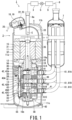
- the motor 12 generates the driving force that rotates the compression mechanism 13.
- the motor 12 is disposed above the compression mechanism 13.
- the motor 12 includes: a cylindrical stator 31 fixed to the inner surface of the airtight container 11; a rotor 32 that is disposed inside the stator 31 and generates the rotational driving force of the compression mechanism 13; and a plurality of lead wires 33 that are drawn from the stator 31 and electrically connected to the pair of sealed terminals 18 and 19.
- the motor 12 may be a motor having a plurality of systems, for example, three-phase windings of two systems like a motor of the conventional compressor, in addition to the mode of the open winding motor.
- the rotating shaft 15 connects the motor 12 and the compression mechanism 13.
- the rotating shaft 15 transmits the rotational driving force generated by the motor 12 to the compression mechanism 13.
- the intermediate portion 15a of the rotating shaft 15 connects the motor 12 and the compression mechanism 13, and is rotatably supported by the main bearing 16.
- the lower end portion 15b of the rotating shaft 15 is rotatably supported by the auxiliary bearing 17.
- the main bearing 16 and the auxiliary bearing 17 are also part of the compression mechanism 13. In other words, the rotating shaft 15 penetrates the compression mechanism 13.
- the compression mechanism 13 compresses the refrigerant introduced into the airtight container 11.
- the compression mechanism 13 sucks in the gaseous refrigerant from the refrigerant piping 8 so as to compress the refrigerant, and discharges the compressed high-temperature and high-pressure refrigerant into the airtight container 11.
- the cylinder 42 closest to the motor 12 is defined as the first cylinder 42A
- the cylinder 42 farthest from the motor 12 is defined as the third cylinder 42C
- the cylinder 42 disposed between the first cylinder 42A and the third cylinder 42C is defined as the second cylinder 42B.
- the main bearing 16 and the first partition plate 45A are fixed in a lump to the second cylinder 42B with a fastening member 46 such as a bolt. That is, the main bearing 16 and the first partition plate 45A are fastened together to the second cylinder 42B with the fastening member 46.
- the main bearing 16 is provided with: a first discharge valve mechanism 51A that discharges the refrigerant compressed in the cylinder chamber 41 of the first cylinder 42A; and a first discharge muffler 52 that covers the first discharge valve mechanism 51A.
- the first discharge valve mechanism 51A opens a discharge port (not shown) so as to discharge the compressed refrigerant into the first discharge muffler 52.
- the refrigerant discharged into the discharge chamber 53 is discharged into the first discharge muffler 52 through the first hole.
- the refrigerant discharged into the first discharge muffler 52 through the first hole joins the refrigerant compressed by the first cylinder 42A.
- the first discharge muffler 52 has a discharge hole (not shown) that spatially connects the inside and outside of the first discharge muffler 52.
- the compressed refrigerant discharged into the first discharge muffler 52 is discharged into the airtight container 11 through the discharge hole.
- first hole may be part of the second hole 57.
- discharge chamber 53 of the second partition plate 45B may be spatially connected to the second discharge muffler 56. That is, the first hole may be spatially connected to the second discharge muffler 56.
- the first cylinder 42A is fixed to a frame 58 with a fastening member 59 such as a bolt, and this frame is fixed to the airtight container 11 by welding, for example, by spot welding at a plurality of points.
- the frame 58 supports the rotor 32, the compression mechanism 13, and the rotating shaft 15 of the motor 12 to the airtight container 11 via the first cylinder 42A. It is preferred that the center of gravity of the rotor 32, the compression mechanism 13, and the rotating shaft 15 of the motor 12 in the height direction of the airtight container 11 is located within the thickness of the frame 58 (i.e., dimension of the compressor 2 in the height direction).
- a plurality of suction pipes 61 are connected to the cylinder chambers 41 of the respective cylinders 42 through the airtight container 11.
- Each cylinder 42 has a suction hole that is spatially connected to each suction pipe 61 and reaches the cylinder chamber 41.
- the first suction pipe 61A is connected to the cylinder chamber 41 of the first cylinder 42A.
- the second suction pipe 61B is connected to the cylinder chamber 41 of the second cylinder 42B.
- the third suction pipe 61C is connected to the cylinder chamber 41 of the third cylinder 42C.
- the accumulator 7 prevents the liquid refrigerant, which has not been completely gasified by the heat absorber 6, from being sucked into the compressor 2.
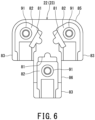
- Fig. 4 is a schematic view of the sealed terminals and the terminal block of the compressor according to the embodiment of the present invention as viewed from above.
- the pair of sealed terminals 18 and 19 of the compressor 2 according to the present embodiment are arranged side by side on the dome-shaped end plate 11b of the airtight container 11.
- the other sealed terminal 19 has substantially the same structure and shape as the sealed terminal 18. Accordingly, the description of the other sealed terminal 19 is omitted.
- the sealed terminal 18 is hereinafter referred to as the first sealed terminal 18, and the other sealed terminal 19 is hereinafter referred to as the second sealed terminal 19.
- the first sealed terminal 18 includes: a substantially disk-shaped main body 71; three pins 72 that penetrate the front and back of the main body 71; three first plate-shaped terminals 75 that are provided on the respective pins 72 and are located outside the airtight container 11; and three second plate-shaped terminals 76 that are provided on the respective pins 72 and are disposed inside the airtight container 11.
- Fig. 2 and Fig. 3 are diagrams of the sealed terminals 18 and 19 when viewed from the extending direction of the pins 72 of the pair of sealed terminals 18 and 19.
- Fig. 2 and Fig. 3 show the sealed terminals 18 and 19 from the direction tilted with respect to the planar view of the compressor 2.
- the main body 71 holds the three pins 72 and the three first plate-shaped terminals 75 such that they are isolated from each other.
- the three pins 72 and the three first plate-shaped terminals 75 are electrically connected to the motor 12.
- the three pins 72 are arranged at the respective vertexes of the equilateral triangle d, center of gravity of which is the center point O of the disk-shaped main body 71. In other words, the three pins 72 are arranged around the center point O at every 120 degree of the center angle.
- Each virtual line passing through each pin 72 from the center point O are defined as a line segment L1. That is, the three line segments L1 substantially trisect the circle in a fan shape.
- the respective first plate-shaped terminals 75 are connected to the power lines 25.
- Each of the first plate-shaped terminals 75 has a front surface 75f as one surface and a back surface 75r as the other surface.
- the front surface 75f and the back surface 75r are in a front-to-back relationship of the first plate-shaped terminal 75.
- the front surface 75f of each first plate-shaped terminal 75 is joined to the corresponding pin 72.
- the other terminal block 23 has substantially the same structure and shape as the terminal block 22. Thus, the description of the other terminal block 23 is omitted.
- the terminal block 22 is hereinafter referred to as the first terminal block 22, and the other terminal block 23 is hereinafter referred to as the second terminal block 23.
- the first terminal block 22 is provided in the first sealed terminal 18, and the second terminal block 23 is provided in the second sealed terminal 19.
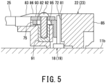
- This fastening member 92 electrically connects a plate-shaped terminal 93 provided at the end of the power line 25 to the first plate-shaped terminal 75, and fastens the first plate-shaped terminal 75 bent by the plate-shaped terminal receiver 82 and the terminal 93 of the power line 25 together so as to fix them to the first terminal block 22.
- the wiring holder 83 of the vertical bar 86 of the first terminal block 22 extends in the bending direction of the first plate-shaped terminal 75 bent on the corresponding plate-shaped terminal receiver 82.
- the wiring holders 83 of the horizontal bar 85 of the first terminal block 22 intersect with the bending direction of the first plate-shaped terminal 75 bent on the corresponding plate-shaped terminal receivers 82, and extend in parallel to the extending direction of the wiring holder 83 of the vertical bar 86 of the first terminal block 22.
- One of the terminal blocks 22 and 23 holds the three power lines 25 connected to the respective first plate-shaped terminals 75 of the corresponding sealed terminals (18 or 19) such that these three power lines 25 are wired to be separated away from the other of the terminal blocks 22 and 23. That is, the first terminal block 22 holds the three power lines 25 connected to the respective first plate-shaped terminals 75 of the first sealed terminal 18 such that these three power lines 25 are wired to be separated away from the second terminal block 23. Similarly, the second terminal block 23 holds the three power lines 25 connected to the respective first plate-shaped terminals 75 of the second sealed terminal 19 such that these three power lines 25 are wired to be separated away from the first terminal block 22.
- the pair of T-shaped terminal blocks 22 and 23 are provided on the pair of sealed terminals 18 and 19 such that the respective horizontal bars 85 of the terminal blocks 22 and 23 face each other. That is, the respective vertical bars 86 of the pair of terminal blocks 22 and 23 extend in the direction away from each other. Since the wiring holders 83 of each of the terminal blocks 22 and 23 extend in parallel to the extending direction of the vertical bar 86 of the corresponding terminal block, one of the terminal blocks 22 and 23 holds the three power lines 25 connected to the respective first plate-shaped terminals 75 of the corresponding sealed terminals (18 or 19) in the direction away from the other of the terminal blocks 22 or 23.
- the compressor 2 and the refrigeration cycle apparatus 1 enable the three first plate-shaped terminals 75 to be bent toward the outside of the triangle D in one of the sealed terminals 18 and 19 without interference.
- the compressor 2 and the refrigeration cycle apparatus 1 enable the three first plate-shaped terminals 75 to be bent toward the outside of the triangle D without interference and to readily connect the power lines 25 having the plate-shaped terminals 93.
Landscapes
- Engineering & Computer Science (AREA)
- Mechanical Engineering (AREA)
- General Engineering & Computer Science (AREA)
- Compressor (AREA)
- Applications Or Details Of Rotary Compressors (AREA)
- Motor Or Generator Frames (AREA)
- Connection Of Motors, Electrical Generators, Mechanical Devices, And The Like (AREA)
Claims (4)
- Ein Kompressor (2), bestehend aus:einem luftdicht verschlossenen Behälter (11);einen Kompressionsmechanismus (13), der in dem luftdichten Behälter (11) angeordnet ist und ein in den luftdichten Behälter (11) eingeführtes Kältemittel komprimiert;einen Motor (12) mit einem zylindrischen Stator (31) und einem Rotor (32), der innerhalb des Stators (31) angeordnet ist und eine Drehantriebskraft des Kompressionsmechanismus (13) erzeugt, wobei der Stator (31) an einer Innenfläche des luftdichten Behälters (11) befestigt ist; undein Paar versiegelter Anschlüsse (18, 19), die in dem luftdichten Behälter (11) angeordnet sind, wobeijeder der abgedichteten Anschlüsse (18, 19) drei plattenförmige Anschlüsse (75) aufweist, die außerhalb des luftdichten Behälters (11) angeordnet sind und elektrisch mit dem Motor (12) verbunden sind; dadurch gekennzeichnet, dasseine Fläche von jedem der drei plattenförmigen Anschlüsse (75) ausgerichtet ist mit jeder Seite eines Dreiecks und jedem der beiden anderen plattenförmigen Anschlüsse auf der einen Fläche so gegenüberliegt, dass drei virtuelle Ebenen, die jeweils die eine Fläche enthalten, das Dreieck über die drei plattenförmigen Anschlüsse (75) bilden; undeine der Ecken des Dreiecks, das von den drei plattenförmigen Anschlüssen (75) eines der abgedichteten Anschlüsse (18, 19) gebildet wird, einer der Ecken des Dreiecks gegenüberliegt, das von den drei plattenförmigen Anschlüssen (75) eines anderen der abgedichteten Anschlüsse (18, 19) gebildet wird.
- Der Kompressor (2) nach Anspruch 1, der ferner ein Paar von Anschlussblöcken für entsprechende abgedichtete Anschlüsse umfasst,
wobei einer der Anschlussblöcke drei Stromleitungen (25) enthält, die mit jeweiligen plattenförmigen Anschlüssen (75) eines entsprechenden abgedichteten Anschlusses (18; 19) so verbunden sind, dass die drei Stromleitungen (25) so verdrahtet sind, dass sie weg von einem anderen Anschlussblock (22) getrennt werden. - Der Kompressor (2) nach Anspruch 1 oder Anspruch 2, wobei:jeder der abgedichteten Anschlüsse (18, 19) drei zweite plattenförmige Anschlüsse aufweist, die im Inneren des luftdichten Behälters angeordnet und elektrisch mit dem Motor (12) verbunden sind;in jedem der abgedichteten Anschlüsse (18, 19) sich Vorder- und Rückseiten eines der drei zweiten plattenförmigen Anschlüsse entlang einer ersten virtuellen Linie erstrecken, die eine von drei virtuellen Linien ist, die im Wesentlichen einen Kreis schneiden, der auf einem Schwerpunkt des Dreiecks in einer Fächerform zentriert ist, während Vorder- und Rückseiten der anderen zwei der drei zweiten plattenförmigen Anschlüsse im Wesentlichen orthogonal zu zweiten virtuellen Linien sind, die die anderen zwei der drei virtuellen Linien sind; underste virtuelle Linien (L1a) jeweiliger abgedichteter Anschlüsse (18, 19) einander an einer Position schneiden, die weiter als eine Mittellinie des luftdichten Behälters (11) liegt, wenn man von das Paar abgedichteter Anschlüsse (18, 19) betrachtet.
- Ein Kühlkreislaufgerät, bestehend aus:den Kompressor (2) nach einem der Ansprüche 1 bis 3;einen Heizkörper (3);eine Expansionsvorrichtung (5);einen Wärmeabsorber (6); undKältemittelleitungen (8), die den Kompressor (2), der Heizkörper (3), das Expansionsvorrichtung (5) und den Wärmeabsorber (6) miteinander verbinden und das Kältemittel zirkulieren lassen.
Applications Claiming Priority (1)
| Application Number | Priority Date | Filing Date | Title |
|---|---|---|---|
| PCT/JP2020/010020 WO2021181463A1 (ja) | 2020-03-09 | 2020-03-09 | 圧縮機、および冷凍サイクル装置 |
Publications (3)
| Publication Number | Publication Date |
|---|---|
| EP4119796A1 EP4119796A1 (de) | 2023-01-18 |
| EP4119796A4 EP4119796A4 (de) | 2023-10-11 |
| EP4119796B1 true EP4119796B1 (de) | 2024-12-25 |
Family
ID=77671251
Family Applications (1)
| Application Number | Title | Priority Date | Filing Date |
|---|---|---|---|
| EP20924926.7A Active EP4119796B1 (de) | 2020-03-09 | 2020-03-09 | Verdichter und kühlkreisvorrichtung |
Country Status (4)
| Country | Link |
|---|---|
| EP (1) | EP4119796B1 (de) |
| JP (2) | JP7405946B2 (de) |
| CN (1) | CN115103962B (de) |
| WO (1) | WO2021181463A1 (de) |
Family Cites Families (14)
| Publication number | Priority date | Publication date | Assignee | Title |
|---|---|---|---|---|
| JP2003013857A (ja) * | 2001-06-28 | 2003-01-15 | Toshiba Kyaria Kk | 密閉形電動圧縮機 |
| JP2007198223A (ja) * | 2006-01-25 | 2007-08-09 | Daikin Ind Ltd | クラスタボディ及び圧縮機 |
| KR200462471Y1 (ko) * | 2007-06-22 | 2012-09-13 | 삼성전자주식회사 | 압축기 |
| JP5117218B2 (ja) * | 2008-02-18 | 2013-01-16 | 東芝キヤリア株式会社 | 密閉型圧縮機及び冷凍サイクル装置 |
| JP5421732B2 (ja) * | 2009-10-30 | 2014-02-19 | 東芝キヤリア株式会社 | 密閉型圧縮機、冷凍サイクル装置 |
| JP5702106B2 (ja) * | 2010-10-13 | 2015-04-15 | 東芝キヤリア株式会社 | 密閉型圧縮機及び冷凍サイクル装置 |
| JP2013024050A (ja) | 2011-07-15 | 2013-02-04 | Daikin Industries Ltd | 圧縮機 |
| US8608514B2 (en) * | 2012-01-26 | 2013-12-17 | Emerson Electric Co. | Connector block with parallel electrical connection |
| US8794999B2 (en) * | 2012-08-10 | 2014-08-05 | Emerson Electric Co. | Hermetic terminal having pin-isolating feature |
| KR102286802B1 (ko) * | 2015-02-04 | 2021-08-09 | 엘지전자 주식회사 | 밀폐형 압축기용 터미널 장치 |
| JP2019021570A (ja) * | 2017-07-20 | 2019-02-07 | 三菱重工サーマルシステムズ株式会社 | ハーメチック端子、ターミナルブロック、ハーメチック端子ユニットおよび圧縮機 |
| JP6732133B2 (ja) * | 2017-07-27 | 2020-07-29 | 三菱電機株式会社 | 圧縮機及び空気調和機の室外機 |
| WO2019030841A1 (ja) | 2017-08-09 | 2019-02-14 | 三菱電機株式会社 | 圧縮機および冷凍サイクル装置 |
| JP6583367B2 (ja) * | 2017-08-21 | 2019-10-02 | ダイキン工業株式会社 | 密閉型圧縮機 |
-
2020
- 2020-03-09 JP JP2022507003A patent/JP7405946B2/ja active Active
- 2020-03-09 EP EP20924926.7A patent/EP4119796B1/de active Active
- 2020-03-09 CN CN202080096716.XA patent/CN115103962B/zh active Active
- 2020-03-09 WO PCT/JP2020/010020 patent/WO2021181463A1/ja not_active Ceased
-
2023
- 2023-12-13 JP JP2023209789A patent/JP2024022665A/ja active Pending
Also Published As
| Publication number | Publication date |
|---|---|
| WO2021181463A1 (ja) | 2021-09-16 |
| CN115103962B (zh) | 2024-07-02 |
| EP4119796A1 (de) | 2023-01-18 |
| JP7405946B2 (ja) | 2023-12-26 |
| JP2024022665A (ja) | 2024-02-16 |
| CN115103962A (zh) | 2022-09-23 |
| JPWO2021181463A1 (de) | 2021-09-16 |
| EP4119796A4 (de) | 2023-10-11 |
Similar Documents
| Publication | Publication Date | Title |
|---|---|---|
| JP5745450B2 (ja) | 圧縮機のインジェクション装置 | |
| JPH0431689A (ja) | スクロール圧縮機およびそれを用いた冷凍サイクル | |
| CN100585186C (zh) | 变容型旋转压缩机 | |
| US20010001923A1 (en) | Air conditioner | |
| JP2009293523A (ja) | 電動圧縮機 | |
| EP4119796A1 (de) | Verdichter und kühlkreisvorrichtung damit | |
| JP6548915B2 (ja) | 圧縮機 | |
| US8579597B2 (en) | Variable capacity type rotary compressor | |
| EP4177470B1 (de) | Wärmequelleneinheit und spiralverdichter | |
| EP3754270A1 (de) | Sammler und kompressor zur klimatisierung | |
| JP7520226B2 (ja) | 圧縮機 | |
| CN205036580U (zh) | 多缸旋转式压缩机 | |
| US12018682B2 (en) | Scroll compressor and air conditioner having same | |
| JP2004308968A (ja) | 熱交換器 | |
| JP7774722B2 (ja) | 圧縮機及び冷凍サイクル装置 | |
| JP6772934B2 (ja) | 電動圧縮機 | |
| JP7849613B2 (ja) | スクロール圧縮機及び冷凍装置 | |
| JP7793755B2 (ja) | ロータリー式圧縮機、および冷凍サイクル装置 | |
| JP7358674B1 (ja) | 圧縮機および空気調和装置 | |
| CN216200158U (zh) | 一种安装稳固的平衡块 | |
| EP2169180A1 (de) | Strömungsmaschine | |
| JP5217869B2 (ja) | 二段圧縮機 | |
| KR20190135277A (ko) | 전동압축기 | |
| WO2018221282A1 (ja) | 圧縮機 | |
| Shishimoto et al. | Development of 3-Cylinder Rotary Compressor for Large Capacity |
Legal Events
| Date | Code | Title | Description |
|---|---|---|---|
| STAA | Information on the status of an ep patent application or granted ep patent |
Free format text: STATUS: THE INTERNATIONAL PUBLICATION HAS BEEN MADE |
|
| PUAI | Public reference made under article 153(3) epc to a published international application that has entered the european phase |
Free format text: ORIGINAL CODE: 0009012 |
|
| STAA | Information on the status of an ep patent application or granted ep patent |
Free format text: STATUS: REQUEST FOR EXAMINATION WAS MADE |
|
| 17P | Request for examination filed |
Effective date: 20220905 |
|
| AK | Designated contracting states |
Kind code of ref document: A1 Designated state(s): AL AT BE BG CH CY CZ DE DK EE ES FI FR GB GR HR HU IE IS IT LI LT LU LV MC MK MT NL NO PL PT RO RS SE SI SK SM TR |
|
| DAV | Request for validation of the european patent (deleted) | ||
| DAX | Request for extension of the european patent (deleted) | ||
| REG | Reference to a national code |
Ref country code: DE Ref legal event code: R079 Free format text: PREVIOUS MAIN CLASS: F04C0029000000 Ipc: F04C0018356000 Ref document number: 602020043862 Country of ref document: DE |
|
| A4 | Supplementary search report drawn up and despatched |
Effective date: 20230913 |
|
| RIC1 | Information provided on ipc code assigned before grant |
Ipc: F04B 39/12 20060101ALI20230907BHEP Ipc: F04B 39/02 20060101ALI20230907BHEP Ipc: F04B 39/00 20060101ALI20230907BHEP Ipc: F04B 35/04 20060101ALI20230907BHEP Ipc: F04C 29/00 20060101ALI20230907BHEP Ipc: F04C 23/00 20060101ALI20230907BHEP Ipc: F04C 18/356 20060101AFI20230907BHEP |
|
| GRAP | Despatch of communication of intention to grant a patent |
Free format text: ORIGINAL CODE: EPIDOSNIGR1 |
|
| STAA | Information on the status of an ep patent application or granted ep patent |
Free format text: STATUS: GRANT OF PATENT IS INTENDED |
|
| INTG | Intention to grant announced |
Effective date: 20240808 |
|
| GRAS | Grant fee paid |
Free format text: ORIGINAL CODE: EPIDOSNIGR3 |
|
| GRAA | (expected) grant |
Free format text: ORIGINAL CODE: 0009210 |
|
| STAA | Information on the status of an ep patent application or granted ep patent |
Free format text: STATUS: THE PATENT HAS BEEN GRANTED |
|
| AK | Designated contracting states |
Kind code of ref document: B1 Designated state(s): AL AT BE BG CH CY CZ DE DK EE ES FI FR GB GR HR HU IE IS IT LI LT LU LV MC MK MT NL NO PL PT RO RS SE SI SK SM TR |
|
| RAP3 | Party data changed (applicant data changed or rights of an application transferred) |
Owner name: CARRIER JAPAN CORPORATION |
|
| REG | Reference to a national code |
Ref country code: GB Ref legal event code: FG4D |
|
| REG | Reference to a national code |
Ref country code: CH Ref legal event code: EP |
|
| REG | Reference to a national code |
Ref country code: DE Ref legal event code: R096 Ref document number: 602020043862 Country of ref document: DE |
|
| REG | Reference to a national code |
Ref country code: IE Ref legal event code: FG4D |
|
| REG | Reference to a national code |
Ref country code: LT Ref legal event code: MG9D |
|
| PG25 | Lapsed in a contracting state [announced via postgrant information from national office to epo] |
Ref country code: HR Free format text: LAPSE BECAUSE OF FAILURE TO SUBMIT A TRANSLATION OF THE DESCRIPTION OR TO PAY THE FEE WITHIN THE PRESCRIBED TIME-LIMIT Effective date: 20241225 |
|
| PG25 | Lapsed in a contracting state [announced via postgrant information from national office to epo] |
Ref country code: FI Free format text: LAPSE BECAUSE OF FAILURE TO SUBMIT A TRANSLATION OF THE DESCRIPTION OR TO PAY THE FEE WITHIN THE PRESCRIBED TIME-LIMIT Effective date: 20241225 |
|
| PG25 | Lapsed in a contracting state [announced via postgrant information from national office to epo] |
Ref country code: BG Free format text: LAPSE BECAUSE OF FAILURE TO SUBMIT A TRANSLATION OF THE DESCRIPTION OR TO PAY THE FEE WITHIN THE PRESCRIBED TIME-LIMIT Effective date: 20241225 |
|
| PG25 | Lapsed in a contracting state [announced via postgrant information from national office to epo] |
Ref country code: NO Free format text: LAPSE BECAUSE OF FAILURE TO SUBMIT A TRANSLATION OF THE DESCRIPTION OR TO PAY THE FEE WITHIN THE PRESCRIBED TIME-LIMIT Effective date: 20250325 |
|
| PG25 | Lapsed in a contracting state [announced via postgrant information from national office to epo] |
Ref country code: GR Free format text: LAPSE BECAUSE OF FAILURE TO SUBMIT A TRANSLATION OF THE DESCRIPTION OR TO PAY THE FEE WITHIN THE PRESCRIBED TIME-LIMIT Effective date: 20250326 Ref country code: LV Free format text: LAPSE BECAUSE OF FAILURE TO SUBMIT A TRANSLATION OF THE DESCRIPTION OR TO PAY THE FEE WITHIN THE PRESCRIBED TIME-LIMIT Effective date: 20241225 |
|
| PGFP | Annual fee paid to national office [announced via postgrant information from national office to epo] |
Ref country code: IT Payment date: 20250228 Year of fee payment: 6 |
|
| PG25 | Lapsed in a contracting state [announced via postgrant information from national office to epo] |
Ref country code: RS Free format text: LAPSE BECAUSE OF FAILURE TO SUBMIT A TRANSLATION OF THE DESCRIPTION OR TO PAY THE FEE WITHIN THE PRESCRIBED TIME-LIMIT Effective date: 20250325 |
|
| REG | Reference to a national code |
Ref country code: NL Ref legal event code: MP Effective date: 20241225 |
|
| PG25 | Lapsed in a contracting state [announced via postgrant information from national office to epo] |
Ref country code: NL Free format text: LAPSE BECAUSE OF FAILURE TO SUBMIT A TRANSLATION OF THE DESCRIPTION OR TO PAY THE FEE WITHIN THE PRESCRIBED TIME-LIMIT Effective date: 20241225 |
|
| REG | Reference to a national code |
Ref country code: AT Ref legal event code: MK05 Ref document number: 1754366 Country of ref document: AT Kind code of ref document: T Effective date: 20241225 |
|
| PG25 | Lapsed in a contracting state [announced via postgrant information from national office to epo] |
Ref country code: SM Free format text: LAPSE BECAUSE OF FAILURE TO SUBMIT A TRANSLATION OF THE DESCRIPTION OR TO PAY THE FEE WITHIN THE PRESCRIBED TIME-LIMIT Effective date: 20241225 |
|
| PG25 | Lapsed in a contracting state [announced via postgrant information from national office to epo] |
Ref country code: PL Free format text: LAPSE BECAUSE OF FAILURE TO SUBMIT A TRANSLATION OF THE DESCRIPTION OR TO PAY THE FEE WITHIN THE PRESCRIBED TIME-LIMIT Effective date: 20241225 |
|
| PG25 | Lapsed in a contracting state [announced via postgrant information from national office to epo] |
Ref country code: ES Free format text: LAPSE BECAUSE OF FAILURE TO SUBMIT A TRANSLATION OF THE DESCRIPTION OR TO PAY THE FEE WITHIN THE PRESCRIBED TIME-LIMIT Effective date: 20241225 |
|
| PG25 | Lapsed in a contracting state [announced via postgrant information from national office to epo] |
Ref country code: IS Free format text: LAPSE BECAUSE OF FAILURE TO SUBMIT A TRANSLATION OF THE DESCRIPTION OR TO PAY THE FEE WITHIN THE PRESCRIBED TIME-LIMIT Effective date: 20250425 |
|
| PG25 | Lapsed in a contracting state [announced via postgrant information from national office to epo] |
Ref country code: PT Free format text: LAPSE BECAUSE OF FAILURE TO SUBMIT A TRANSLATION OF THE DESCRIPTION OR TO PAY THE FEE WITHIN THE PRESCRIBED TIME-LIMIT Effective date: 20250428 |
|
| PG25 | Lapsed in a contracting state [announced via postgrant information from national office to epo] |
Ref country code: EE Free format text: LAPSE BECAUSE OF FAILURE TO SUBMIT A TRANSLATION OF THE DESCRIPTION OR TO PAY THE FEE WITHIN THE PRESCRIBED TIME-LIMIT Effective date: 20241225 |
|
| PG25 | Lapsed in a contracting state [announced via postgrant information from national office to epo] |
Ref country code: RO Free format text: LAPSE BECAUSE OF FAILURE TO SUBMIT A TRANSLATION OF THE DESCRIPTION OR TO PAY THE FEE WITHIN THE PRESCRIBED TIME-LIMIT Effective date: 20241225 Ref country code: AT Free format text: LAPSE BECAUSE OF FAILURE TO SUBMIT A TRANSLATION OF THE DESCRIPTION OR TO PAY THE FEE WITHIN THE PRESCRIBED TIME-LIMIT Effective date: 20241225 |
|
| PG25 | Lapsed in a contracting state [announced via postgrant information from national office to epo] |
Ref country code: SK Free format text: LAPSE BECAUSE OF FAILURE TO SUBMIT A TRANSLATION OF THE DESCRIPTION OR TO PAY THE FEE WITHIN THE PRESCRIBED TIME-LIMIT Effective date: 20241225 |
|
| PG25 | Lapsed in a contracting state [announced via postgrant information from national office to epo] |
Ref country code: CZ Free format text: LAPSE BECAUSE OF FAILURE TO SUBMIT A TRANSLATION OF THE DESCRIPTION OR TO PAY THE FEE WITHIN THE PRESCRIBED TIME-LIMIT Effective date: 20241225 |
|
| PG25 | Lapsed in a contracting state [announced via postgrant information from national office to epo] |
Ref country code: SE Free format text: LAPSE BECAUSE OF FAILURE TO SUBMIT A TRANSLATION OF THE DESCRIPTION OR TO PAY THE FEE WITHIN THE PRESCRIBED TIME-LIMIT Effective date: 20241225 |
|
| REG | Reference to a national code |
Ref country code: DE Ref legal event code: R097 Ref document number: 602020043862 Country of ref document: DE |
|
| PG25 | Lapsed in a contracting state [announced via postgrant information from national office to epo] |
Ref country code: DK Free format text: LAPSE BECAUSE OF FAILURE TO SUBMIT A TRANSLATION OF THE DESCRIPTION OR TO PAY THE FEE WITHIN THE PRESCRIBED TIME-LIMIT Effective date: 20241225 |
|
| PG25 | Lapsed in a contracting state [announced via postgrant information from national office to epo] |
Ref country code: MC Free format text: LAPSE BECAUSE OF FAILURE TO SUBMIT A TRANSLATION OF THE DESCRIPTION OR TO PAY THE FEE WITHIN THE PRESCRIBED TIME-LIMIT Effective date: 20241225 |
|
| REG | Reference to a national code |
Ref country code: CH Ref legal event code: H13 Free format text: ST27 STATUS EVENT CODE: U-0-0-H10-H13 (AS PROVIDED BY THE NATIONAL OFFICE) Effective date: 20251023 |
|
| PLBE | No opposition filed within time limit |
Free format text: ORIGINAL CODE: 0009261 |
|
| STAA | Information on the status of an ep patent application or granted ep patent |
Free format text: STATUS: NO OPPOSITION FILED WITHIN TIME LIMIT |
|
| PG25 | Lapsed in a contracting state [announced via postgrant information from national office to epo] |
Ref country code: LU Free format text: LAPSE BECAUSE OF NON-PAYMENT OF DUE FEES Effective date: 20250309 |
|
| 26N | No opposition filed |
Effective date: 20250926 |
|
| REG | Reference to a national code |
Ref country code: BE Ref legal event code: MM Effective date: 20250331 |
|
| PG25 | Lapsed in a contracting state [announced via postgrant information from national office to epo] |
Ref country code: BE Free format text: LAPSE BECAUSE OF NON-PAYMENT OF DUE FEES Effective date: 20250331 |
|
| PG25 | Lapsed in a contracting state [announced via postgrant information from national office to epo] |
Ref country code: CH Free format text: LAPSE BECAUSE OF NON-PAYMENT OF DUE FEES Effective date: 20250331 |
|
| PG25 | Lapsed in a contracting state [announced via postgrant information from national office to epo] |
Ref country code: IE Free format text: LAPSE BECAUSE OF NON-PAYMENT OF DUE FEES Effective date: 20250309 |
|
| PGFP | Annual fee paid to national office [announced via postgrant information from national office to epo] |
Ref country code: GB Payment date: 20260220 Year of fee payment: 7 |
|
| PGFP | Annual fee paid to national office [announced via postgrant information from national office to epo] |
Ref country code: DE Payment date: 20260219 Year of fee payment: 7 |
|
| PGFP | Annual fee paid to national office [announced via postgrant information from national office to epo] |
Ref country code: FR Payment date: 20260219 Year of fee payment: 7 |