EP4112851B1 - Serrure de véhicule automobile, en particulier serrure de portière de véhicule automobile - Google Patents
Serrure de véhicule automobile, en particulier serrure de portière de véhicule automobile Download PDFInfo
- Publication number
- EP4112851B1 EP4112851B1 EP22190738.9A EP22190738A EP4112851B1 EP 4112851 B1 EP4112851 B1 EP 4112851B1 EP 22190738 A EP22190738 A EP 22190738A EP 4112851 B1 EP4112851 B1 EP 4112851B1
- Authority
- EP
- European Patent Office
- Prior art keywords
- lever
- motor vehicle
- securing
- securing lever
- drive
- Prior art date
- Legal status (The legal status is an assumption and is not a legal conclusion. Google has not performed a legal analysis and makes no representation as to the accuracy of the status listed.)
- Active
Links
- 239000000463 material Substances 0.000 claims description 11
- 229920003023 plastic Polymers 0.000 claims description 10
- 239000004033 plastic Substances 0.000 claims description 10
- 230000007246 mechanism Effects 0.000 claims description 4
- 230000000694 effects Effects 0.000 description 2
- 238000002347 injection Methods 0.000 description 2
- 239000007924 injection Substances 0.000 description 2
- 238000000034 method Methods 0.000 description 2
- 101100204059 Caenorhabditis elegans trap-2 gene Proteins 0.000 description 1
- 230000009471 action Effects 0.000 description 1
- 230000008859 change Effects 0.000 description 1
- 230000000052 comparative effect Effects 0.000 description 1
- 230000003247 decreasing effect Effects 0.000 description 1
- 230000005489 elastic deformation Effects 0.000 description 1
- 230000002349 favourable effect Effects 0.000 description 1
- 210000003746 feather Anatomy 0.000 description 1
- 239000000945 filler Substances 0.000 description 1
- 239000000446 fuel Substances 0.000 description 1
- 230000003993 interaction Effects 0.000 description 1
- 238000004519 manufacturing process Methods 0.000 description 1
- 230000008569 process Effects 0.000 description 1
- 230000002787 reinforcement Effects 0.000 description 1
- 239000007787 solid Substances 0.000 description 1
- 239000000243 solution Substances 0.000 description 1
Images


Classifications
-
- E—FIXED CONSTRUCTIONS
- E05—LOCKS; KEYS; WINDOW OR DOOR FITTINGS; SAFES
- E05B—LOCKS; ACCESSORIES THEREFOR; HANDCUFFS
- E05B15/00—Other details of locks; Parts for engagement by bolts of fastening devices
- E05B15/0053—Other details of locks; Parts for engagement by bolts of fastening devices means providing a stable, i.e. indexed, position of lock parts
-
- E—FIXED CONSTRUCTIONS
- E05—LOCKS; KEYS; WINDOW OR DOOR FITTINGS; SAFES
- E05B—LOCKS; ACCESSORIES THEREFOR; HANDCUFFS
- E05B81/00—Power-actuated vehicle locks
- E05B81/54—Electrical circuits
- E05B81/90—Manual override in case of power failure
-
- E—FIXED CONSTRUCTIONS
- E05—LOCKS; KEYS; WINDOW OR DOOR FITTINGS; SAFES
- E05B—LOCKS; ACCESSORIES THEREFOR; HANDCUFFS
- E05B15/00—Other details of locks; Parts for engagement by bolts of fastening devices
- E05B15/04—Spring arrangements in locks
-
- E—FIXED CONSTRUCTIONS
- E05—LOCKS; KEYS; WINDOW OR DOOR FITTINGS; SAFES
- E05B—LOCKS; ACCESSORIES THEREFOR; HANDCUFFS
- E05B77/00—Vehicle locks characterised by special functions or purposes
- E05B77/22—Functions related to actuation of locks from the passenger compartment of the vehicle
- E05B77/24—Functions related to actuation of locks from the passenger compartment of the vehicle preventing use of an inner door handle, sill button, lock knob or the like
- E05B77/26—Functions related to actuation of locks from the passenger compartment of the vehicle preventing use of an inner door handle, sill button, lock knob or the like specially adapted for child safety
- E05B77/265—Functions related to actuation of locks from the passenger compartment of the vehicle preventing use of an inner door handle, sill button, lock knob or the like specially adapted for child safety hand actuated, e.g. by a lever at the edge of the door
-
- E—FIXED CONSTRUCTIONS
- E05—LOCKS; KEYS; WINDOW OR DOOR FITTINGS; SAFES
- E05B—LOCKS; ACCESSORIES THEREFOR; HANDCUFFS
- E05B77/00—Vehicle locks characterised by special functions or purposes
- E05B77/22—Functions related to actuation of locks from the passenger compartment of the vehicle
- E05B77/24—Functions related to actuation of locks from the passenger compartment of the vehicle preventing use of an inner door handle, sill button, lock knob or the like
- E05B77/28—Functions related to actuation of locks from the passenger compartment of the vehicle preventing use of an inner door handle, sill button, lock knob or the like for anti-theft purposes, e.g. double-locking or super-locking
- E05B77/283—Functions related to actuation of locks from the passenger compartment of the vehicle preventing use of an inner door handle, sill button, lock knob or the like for anti-theft purposes, e.g. double-locking or super-locking initiated by hand actuation, e.g. by using a mechanical key
-
- E—FIXED CONSTRUCTIONS
- E05—LOCKS; KEYS; WINDOW OR DOOR FITTINGS; SAFES
- E05B—LOCKS; ACCESSORIES THEREFOR; HANDCUFFS
- E05B15/00—Other details of locks; Parts for engagement by bolts of fastening devices
- E05B15/04—Spring arrangements in locks
- E05B2015/0468—Spring arrangements in locks made of one piece with a lock part
-
- E—FIXED CONSTRUCTIONS
- E05—LOCKS; KEYS; WINDOW OR DOOR FITTINGS; SAFES
- E05B—LOCKS; ACCESSORIES THEREFOR; HANDCUFFS
- E05B81/00—Power-actuated vehicle locks
- E05B81/02—Power-actuated vehicle locks characterised by the type of actuators used
- E05B81/04—Electrical
- E05B81/06—Electrical using rotary motors
-
- E—FIXED CONSTRUCTIONS
- E05—LOCKS; KEYS; WINDOW OR DOOR FITTINGS; SAFES
- E05B—LOCKS; ACCESSORIES THEREFOR; HANDCUFFS
- E05B81/00—Power-actuated vehicle locks
- E05B81/12—Power-actuated vehicle locks characterised by the function or purpose of the powered actuators
- E05B81/16—Power-actuated vehicle locks characterised by the function or purpose of the powered actuators operating on locking elements for locking or unlocking action
-
- E—FIXED CONSTRUCTIONS
- E05—LOCKS; KEYS; WINDOW OR DOOR FITTINGS; SAFES
- E05B—LOCKS; ACCESSORIES THEREFOR; HANDCUFFS
- E05B81/00—Power-actuated vehicle locks
- E05B81/24—Power-actuated vehicle locks characterised by constructional features of the actuator or the power transmission
- E05B81/32—Details of the actuator transmission
- E05B81/34—Details of the actuator transmission of geared transmissions
- E05B81/36—Geared sectors, e.g. fan-shaped gears
Definitions
- the invention relates to a motor vehicle lock, in particular a motor vehicle door lock, with a locking mechanism consisting essentially of a rotary latch and a pawl, further with a security device, for example a central locking device and/or an anti-theft device and/or a child safety device, and with an emergency actuation element for the security device, wherein the safety device has at least one first safety lever, which can be acted upon by both a first motor drive and an emergency actuation lever as part of the emergency actuation element.
- the motor vehicle lock is typically a motor vehicle door lock, i.e. a motor vehicle lock that is attached to or in a motor vehicle door, a motor vehicle lid, a motor vehicle tailgate, a motor vehicle front hood, etc.
- motor vehicle lock within the scope of the invention also includes locks in or on motor vehicles, for example in connection with a seat lock, a fuel filler flap lock, etc. Typically, however, it refers to a motor vehicle door lock.
- Such motor vehicle door locks generally have a security device.
- the security device can be a central locking device, with the help of which all motor vehicle door locks of an associated motor vehicle are locked, in such a way that actuation from the outside is not possible, but the associated motor vehicle door can still be opened from the inside can.
- an anti-theft device ensures that that in the "ON" position neither internal nor external actuation is permitted. With a child safety device, however, only the rear side doors of the motor vehicle are locked from the inside and cannot therefore be opened from the inside. However, opening from the outside is still possible.
- the safety device has the first safety lever, which is usually acted upon by the motor drive or a first motor drive.
- the safety device can typically be transferred to its two functional positions “ON” or “OFF”. This can be done, for example, with the help of a remote control to control the motor drive.
- the emergency actuation element is provided.
- the safety device can be manually transferred at least from its "OFF” position to the "ON” position. Then the emergency actuation element is an emergency opening element. In principle, the emergency actuation element can also ensure that the safety device is inserted, i.e. is transferred from its "OFF” position to the "ON” position. Then the emergency actuation element is designed as an emergency locking element.
- a first locking element and a second locking element are realized, which can each be acted upon with the help of their own motor drives, namely a first motor drive and a second motor drive.
- There is also an additional Manually operable locking button is implemented, which predominantly takes over or can take over the function of the emergency actuation element.
- a similar procedure is followed. This is about an actuating device which is equipped with an anti-theft device, a central locking device, a child safety device and an actuating device for opening the lock.
- the anti-theft device includes an anti-theft lever that can be pivoted using its own electric drive.
- the central locking device is equipped with another central locking lever that has its own electric drive.
- the anti-theft lever and the central locking lever are rotatably mounted on a common axis. This has basically proven itself.
- Two drive motors are also implemented, on the one hand a locking motor and on the other hand an anti-theft or child safety motor.
- the locking motor acts on a central locking lever
- the anti-theft/child lock motor acts on a locking lever.
- the central locking lever and the locking lever are mounted pivotably about a common axis.
- the invention is based on the technical problem of further developing such a motor vehicle lock and in particular a motor vehicle door lock in such a way that a simple and functional emergency actuation is provided.
- the invention proposes in a generic motor vehicle lock and in particular a motor vehicle door lock that the first security lever has a spring for its positioning, the security lever having a stop for the emergency actuation element, the stop interacting with a pin of the emergency actuation element , wherein the security device has two security levers, namely a first security lever and a second security lever, the first security lever being designed as an anti-theft lever and whereas the second security lever is a central locking lever, both security levers being mounted coaxially about an axis of rotation, whereby two motor drives are implemented, the first drive working on the first security lever, while the second drive interacts with the second security lever, the first motor drive being an anti-theft drive, with the help of which the anti-theft lever pivots about its axis or .
- the axis of rotation can perform, whereby the second motor drive or central locking drive (8) ensures that the central locking lever is also subjected to pivoting movements about the common axis of rotation.
- the first safety lever on the one hand and the spring on the other hand can be designed separately and, for example, consist of different materials.
- the first safety lever and the spring are made of the same material, for example plastic.
- the design is usually such that the first safety lever has a guide groove for a housing pin.
- the housing pin is usually molded onto a lock housing as part of the motor vehicle lock. Since the lock housing is typically made of plastic, the housing pin is also usually made of plastic and can easily be defined on the lock housing in question. This provides favorable plastic-plastic friction conditions between, on the one hand, the housing pin and, on the other hand, the first safety lever.
- the guide groove is designed with an enlarged cross-section in the area of the respective end positions of the first safety lever.
- This cross-sectional enlargement creates a particularly sensitive and clear Positioning of the safety lever provided.
- the cross-sectional enlargement in the area of the two end positions of the guide groove ensures that the housing pin passing through the guide groove is held in the respective end position and can only be moved out of the end position with a more or less pronounced force.
- Such a defined positioning of the safety lever is of particular importance for both motor operation and operation with the emergency actuation element. Because, for example, the safe assumption of the functional position “anti-theft protection ON” is of particular importance in order to ensure that the associated motor vehicle is also reliably protected against theft.
- the use of the spring assigned to the security lever now supports the assumption of both the previously mentioned position with the anti-theft device inserted and the situation in which the anti-theft device is designed in the example case, i.e. the functional position "anti-theft device OFF".
- the guide groove is limited in its longitudinal extent on the one hand by a radially inner stop wall with respect to an axis of rotation of the safety lever and on the other hand by a radially outer spring wall as a spring.
- the longitudinally extending guide groove has two longitudinal walls, namely the radially inner stop wall and the radially outer spring wall. These include the stop wall and the spring wall is generally arcuate compared to the axis of rotation for the safety lever.
- the design is also advantageously made in such a way that the spring wall in the area of the two end positions of the safety lever is designed to be material-reinforced compared to a connection area between the two end positions.
- This different material thickness or material thickness of the spring wall supports or fundamentally adjusts its spring effect.
- the invention is based on the knowledge that the housing pin that dips into the guide groove can only slightly elastically deform the spring wall in the area of the end positions with the material reinforcement of the spring wall implemented there.
- the connecting region of the spring wall that couples the two end positions together allows a relatively increased elastic deformation with the help of the housing pin moving within the guide groove when the safety lever is adjusted. This greater deformation is achieved and provided by the fact that the connection area has a smaller material thickness of the spring wall compared to the two end positions.
- connection area between the two end positions can be easily overcome because the material thickness of the spring wall is smaller here. In any case, this corresponds to an increasing actuation force of the pivoting movement of the safety lever when leaving the end position.
- the spring force drops in the connection area between the two end positions, so that the relevant pin is transferred to the end position with spring support.
- the safety lever also has a stop for the emergency operating lever or the emergency operating element. Because the safety lever is generally made of plastic and is designed as a plastic injection molded part, the stop can easily be molded onto the safety lever. The stop generally interacts with a pin on the emergency control lever. The design is advantageously such that the pin projects vertically relative to the longitudinally extended emergency actuation lever.
- the pin can pass through an opening in a second safety lever mounted coaxially with the first safety lever.
- the safety device regularly not only has the first safety lever, but also usually also has a second safety lever.
- the first security lever may be designed as an anti-theft lever, whereas the second security lever is or can be a central locking lever.
- Both security levers are equipped with an associated motor drive, namely the first motor drive as an anti-theft device and the second motor drive as a central locking drive.
- an emergency actuation of the anti-theft lever in the example case now requires that the pin on the emergency actuation lever passes through the opening on the central locking lever, which is usually mounted above the anti-theft lever, and can also take effect. This is the only way to ensure that the pin on the emergency operating lever can interact with the stop on the first security lever or anti-theft lever.
- An actuation nut is generally provided to act on the emergency actuation lever.
- the actuation nut is rotatably mounted in the lock housing.
- the operating nut may have an operating slot.
- a relatively long emergency operating lever can be used via the operating nut in order to be able to actuate the safety lever effectively. This is ensured by the perfect positioning of the safety lever as a result of the interaction between the housing pin and the guide groove.
- the housing pin is advantageously elliptical or approximately elliptical in shape, so that it can also take on the function of a stop for the safety lever.
- a motor vehicle lock in which, first of all, perfect both motorized and manual adjustment of the security lever is provided.
- the safety lever is equipped with a spring which, in conjunction with a housing pin engaging in a guide groove of the safety lever, ensures that the safety lever can assume two stable end positions corresponding to the functional positions "ON" and "OFF" of the safety device in a perfect and reproducible manner.
- This also applies if an emergency actuation is required, taking into account a relatively large local distance between, on the one hand, the safety lever and, on the other hand, the actuation nut, with the help of which the emergency actuation lever bridging the distance is acted upon.
- the use of a pin standing vertically on the emergency actuation lever to act on the safety lever also ensures that it is possible to advantageously work with two safety levers arranged coaxially to one another in order to achieve a particularly compact structure to realize.
- the actuation nut is usually designed as an external locking nut, so it at least ensures that an external lock can be canceled in this way.
- the external locking nut works via the operating lever on the anti-theft lever, which in this case represents the first security lever.
- the opening in the central locking lever which is coaxially mounted and arranged above it, is penetrated using the pin. This is where the main advantages can be seen.
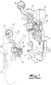
- a motor vehicle lock is shown, which according to the exemplary embodiment is designed as a motor vehicle door lock and may be implemented, for example, on a front or rear side door of an associated motor vehicle.
- the motor vehicle lock has a locking device 1, 2 consisting essentially of a rotary latch 1 and a pawl 2, which are arranged predominantly perpendicular to the plane of the drawing in the context of the illustration.
- An actuating lever chain 3, 4 and a safety device 5, 6, 7, 8 are also important for the following considerations.
- the security device 5, 6, 7, 8 has two security levers 5, 6, namely a first security lever 5 and a second security lever 6.
- the first security lever 5 is designed as an anti-theft lever 5, whereas the second security lever 6 is a central locking lever 6 acts.
- Both safety levers are 5.6 Fig. 1 coaxial, that is, mounted on the same axis, around an axis of rotation A.
- the design is such that the central locking lever 6 is arranged above the anti-theft lever 5 when viewed from above.
- the safety device 5, 6, 7, 8 includes two motor drives 7, 8.
- the first drive 7 works on the first safety lever 5, while the second drive 8 interacts with the second safety lever 6.
- the first motor drive 7 is an anti-theft drive, with the help of which the first security lever or anti-theft lever 5 can perform pivoting movements about its axis or the axis of rotation A.
- the second motor drive or central locking drive 8 ensures that the second safety lever 6 or central locking lever 6 is also subjected to pivoting movements about the common axis or axis of rotation A.
- the first safety lever or central locking lever 5 will be considered primarily, as can be seen from the Fig. 2 and 3 can understand.
- the first motor drive or anti-theft device drive 7 in the “anti-theft device ON” position ensures that the locking mechanism 1, 2 cannot be opened using an internal operating lever 3 an external operating lever 4 is also possible as an essential component of the operating lever chain 3, 4.
- the "anti-theft protection OFF" position corresponds to the fact that the locking mechanism 1, 2 can be opened both via the internal operating lever 3 and the external operating lever 4.
- the security lever or first security lever 5 or the anti-theft lever 5 has a spring 5a for its positioning, which can be seen in particular from the detailed illustration in accordance with Fig. 3 can understand.
- the spring 5a is made of the same material as the safety lever 5 because the safety lever 5 is made of plastic according to the exemplary embodiment, for example as a plastic injection molded part.
- the safety lever 5 has a guide groove 5c, into which a housing pin 12 'engages.
- the housing pin 12 ' is formed on a lock housing 12, which is also made of plastic.
- the guide groove 5c of the safety lever 5 has two end positions and has an enlarged cross-section in this area. These two end positions are in the Fig. 3 represented by a solid and dashed representation of the housing pin 12 'immersing into the guide groove 5c.
- the longitudinal extent of the guide groove 5c is delimited on the one hand by a stop wall 5b and on the other hand by a spring wall 5a as a spring 5a.
- the overall design is such that the stop wall 5b of the guide groove 5c is arranged radially inwardly in relation to the axis of rotation A of the safety lever 5, while the spring wall 5a is arranged in a radially outer arrangement in comparison to the said axis of rotation A.
- the Stop wall 5b and the spring wall 5a are each curved in shape compared to said axis of rotation A.
- the spring wall 5a in the area of the two end positions of the safety lever 5 is designed to be material-reinforced compared to a connection area 5d connecting the two end positions.
- the safety lever 5 also has a stop 5e for the emergency actuation element 9, 10, 11.
- the emergency actuation element 9, 10, 11 is composed of an actuation nut or emergency actuation nut 9 and an emergency actuation lever 10.
- the emergency operating lever 10 is connected to the operating nut 9 in a pivoted manner.
- the emergency operating lever 10 has a pin 11 which, according to the exemplary embodiment, is connected to the end of the emergency operating lever 10. Rotary movements of the operating nut 9 consequently lead to the emergency operating lever 10 and with it the end pin 11 being moved linearly back and forth.
- the pin 11 as part of the emergency actuation element 9, 10, 11 can interact overall with the stop 5e on the safety lever 5. In this way, rotational movements of the actuating nut 9 result in the security lever 5 being manually moved at least to the end position, which corresponds to the “anti-theft protection OFF” position. In this way, with the help of the emergency actuation element 9, 10, 11, the anti-theft lever 5 in the exemplary embodiment can be moved to the "OFF" position and consequently the external locking can be canceled. An associated motor vehicle door can then easily be opened from the outside even if the motor drive 7 fails.
Claims (8)
- Serrure de véhicule automobile, en particulier serrure de porte de véhicule automobile, comportant un mécanisme de verrouillage (1, 2) composé essentiellement d'un loquet rotatif (1) et d'un cliquet d'arrêt (2), comportant en outre un dispositif de sécurité (5, 6, 7, 8) et comportant un élément d'actionnement de secours (9, 10, 11) pour le dispositif de sécurité (5, 6, 7, 8), le dispositif de sécurité (5, 6, 7, 8) présentant au moins un premier levier de sécurité (5), lequel peut être sollicité tant par un premier entraînement motorisé (7) que par un levier d'actionnement de secours (10) comme partie de l'élément d'actionnement de secours (9, 10, 11), le premier levier de sécurité (5) présentant un ressort (5a) pour son positionnement, le levier de sécurité (5) présentant une butée (5e) pour l'élément d'actionnement de secours (9, 10, 11), la butée (5e) interagissant avec un tourillon (11) de l'élément d'actionnement de secours (9, 10, 11), le dispositif de sécurité (5, 6, 7, 8) disposant de deux leviers de sécurité (5, 6), à savoir un premier levier de sécurité (5) et un second levier de sécurité (6), le premier levier de sécurité (5) étant réalisé en tant que levier de sécurité antivol (5), tandis que le second levier de sécurité (6) est un levier de verrouillage central (6), les deux leviers de sécurité (5, 6) étant montés de manière coaxiale autour d'un axe de rotation A, deux entraînements motorisés (7, 8) étant réalisés, le premier entraînement (7) travaillant sur le premier levier de sécurité (5), et le second entraînement (8) interagissant avec le second levier de sécurité (6), le premier entraînement motorisé (7) étant un entraînement de sécurité antivol, à l'aide duquel le levier de sécurité antivol (5) peut effectuer des mouvements de pivotement autour de son axe ou de l'axe de rotation A, le second entraînement motorisé ou l'entraînement de verrouillage central (8) assurant, par contre, que le levier de verrouillage central (6) soit également sollicité pour des mouvements de pivotement autour de l'axe de rotation A commun.
- Serrure de véhicule automobile selon la revendication 1,
caractérisée en ce que le premier levier de sécurité (5) et le ressort (5a) sont réalisés à partir du même matériau, par exemple en matière plastique. - Serrure de véhicule automobile selon la revendication 1 ou 2,
caractérisée en ce que le premier levier de sécurité (5) présente une rainure de guidage (5c) pour un tourillon de boîtier (12'). - Serrure de véhicule automobile selon la revendication 3,
caractérisée en ce que la rainure de guidage (5c) est réalisée avec une section transversale agrandie dans la zone de positions finales respectives du premier levier de sécurité (5). - Serrure de véhicule automobile selon la revendication 3 ou 4,
caractérisée en ce que la rainure de guidage (5c) est délimitée dans son extension longitudinale, d'une part, par une paroi de butée (5b) radialement intérieure par rapport à un axe de rotation (A) du levier de sécurité (5) et, d'autre part, par une paroi de ressort (5a) radialement extérieure en tant que ressort (5a). - Serrure de véhicule automobile selon la revendication 5,
caractérisée en ce que la paroi de butée (5b) et la paroi de ressort (5a) sont respectivement réalisées en forme d'arc de cercle par rapport à l'axe de rotation (A). - Serrure de véhicule automobile selon la revendication 5 ou 6,
caractérisée en ce que la paroi de ressort (5a) est réalisée de manière renforcée en termes de matériau dans la zone des positions finales du levier de sécurité (5) par comparaison avec une zone de liaison (5d) entre les deux positions finales. - Serrure de véhicule automobile selon la revendication 1,
caractérisée en ce que le tourillon (11) traverse une ouverture (13) dans un second levier de sécurité (6) monté de manière coaxiale par rapport au premier levier de sécurité (5).
Applications Claiming Priority (3)
| Application Number | Priority Date | Filing Date | Title |
|---|---|---|---|
| DE102019133324.5A DE102019133324A1 (de) | 2019-12-06 | 2019-12-06 | Kraftfahrzeug-Schloss, insbesondere Kraftfahrzeug-Türschloss |
| PCT/DE2020/100990 WO2021110206A1 (fr) | 2019-12-06 | 2020-11-23 | Serrure de véhicule automobile, en particulier serrure de portière de véhicule automobile |
| EP20819618.8A EP4069922B1 (fr) | 2019-12-06 | 2020-11-23 | Serrure de véhicule automobile, en particulier serrure de portière de véhicule automobile |
Related Parent Applications (2)
| Application Number | Title | Priority Date | Filing Date |
|---|---|---|---|
| EP20819618.8A Division-Into EP4069922B1 (fr) | 2019-12-06 | 2020-11-23 | Serrure de véhicule automobile, en particulier serrure de portière de véhicule automobile |
| EP20819618.8A Division EP4069922B1 (fr) | 2019-12-06 | 2020-11-23 | Serrure de véhicule automobile, en particulier serrure de portière de véhicule automobile |
Publications (2)
| Publication Number | Publication Date |
|---|---|
| EP4112851A1 EP4112851A1 (fr) | 2023-01-04 |
| EP4112851B1 true EP4112851B1 (fr) | 2024-01-17 |
Family
ID=73698496
Family Applications (2)
| Application Number | Title | Priority Date | Filing Date |
|---|---|---|---|
| EP22190738.9A Active EP4112851B1 (fr) | 2019-12-06 | 2020-11-23 | Serrure de véhicule automobile, en particulier serrure de portière de véhicule automobile |
| EP20819618.8A Active EP4069922B1 (fr) | 2019-12-06 | 2020-11-23 | Serrure de véhicule automobile, en particulier serrure de portière de véhicule automobile |
Family Applications After (1)
| Application Number | Title | Priority Date | Filing Date |
|---|---|---|---|
| EP20819618.8A Active EP4069922B1 (fr) | 2019-12-06 | 2020-11-23 | Serrure de véhicule automobile, en particulier serrure de portière de véhicule automobile |
Country Status (5)
| Country | Link |
|---|---|
| US (1) | US20230045645A1 (fr) |
| EP (2) | EP4112851B1 (fr) |
| CN (1) | CN114787469B (fr) |
| DE (1) | DE102019133324A1 (fr) |
| WO (1) | WO2021110206A1 (fr) |
Families Citing this family (2)
| Publication number | Priority date | Publication date | Assignee | Title |
|---|---|---|---|---|
| DE102021133964A1 (de) | 2021-12-21 | 2023-06-22 | Kiekert Aktiengesellschaft | Kraftfahrzeug-Schloss, insbesondere Kraftfahrzeug-Türschloss |
| DE102021133965A1 (de) | 2021-12-21 | 2023-06-22 | Kiekert Aktiengesellschaft | Kraftfahrzeug-Schloss, insbesondere Kraftfahrzeug-Türschloss |
Family Cites Families (19)
| Publication number | Priority date | Publication date | Assignee | Title |
|---|---|---|---|---|
| DE3902776A1 (de) * | 1988-08-13 | 1990-02-15 | Kiekert Gmbh Co Kg | Kraftfahrzeugtuerverschluss mit zentralverriegelungsantrieb und diebstahlsicherung |
| DE9011530U1 (fr) * | 1990-08-08 | 1990-10-11 | Bomoro Bocklenberg & Motte Gmbh & Co Kg, 5600 Wuppertal, De | |
| DE19756266A1 (de) | 1997-12-18 | 1999-06-24 | Mannesmann Vdo Ag | Schließeinrichtung |
| DE19702420C5 (de) * | 1997-01-24 | 2009-12-31 | Audi Ag | Steuervorrichtung für einen Verschluß, insbesondere von Kraftfahrzeugtüren |
| DE19814003C1 (de) * | 1998-03-28 | 1999-08-26 | Kiekert Ag | Kraftfahrzeugtürverschluß |
| FR2782108B1 (fr) * | 1998-08-05 | 2001-09-28 | Valeo Securite Habitacle | Serrure de fermeture pour une porte de vehicule automobile et vehicule automobile equipe de cette serrure |
| DE29913464U1 (de) * | 1999-07-31 | 1999-12-16 | Kiekert Ag | Kraftfahrzeugtürverschluß |
| GB0323268D0 (en) * | 2003-10-04 | 2003-11-05 | Arvinmeritor Light Vehicle Sys | Lock mechanism |
| DE102005052190A1 (de) | 2005-10-28 | 2007-05-03 | Kiekert Ag | Kraftfahrzeugtürschloss |
| DE102008018500A1 (de) * | 2007-09-21 | 2009-04-02 | BROSE SCHLIEßSYSTEME GMBH & CO. KG | Kraftfahrzeugschloß |
| GB2458574B (en) * | 2008-03-26 | 2011-06-08 | Mitsui Mining & Smelting Co | Door lock apparatus |
| JP4564077B2 (ja) | 2008-04-23 | 2010-10-20 | 三井金属鉱業株式会社 | 自動車用ドアラッチ装置 |
| DE112013002526T5 (de) * | 2012-05-16 | 2015-02-19 | Magna Closures Inc. | Türschloss mit Doppelschließfunktion |
| DE202013102845U1 (de) * | 2013-06-28 | 2014-09-29 | BROSE SCHLIEßSYSTEME GMBH & CO. KG | Kraftfahrzeugschloss |
| DE102014113495A1 (de) * | 2014-09-18 | 2016-03-24 | Huf Hülsbeck & Fürst Gmbh & Co. Kg | Türgriffanordnung für ein Kraftfahrzeug |
| DE102014114347A1 (de) * | 2014-10-02 | 2016-04-07 | Kiekert Ag | Kraftfahrzeugtürverschluss |
| JP6450991B2 (ja) * | 2014-10-29 | 2019-01-16 | 三井金属アクト株式会社 | 車両用ドアラッチ装置 |
| DE102015116283A1 (de) | 2015-09-25 | 2017-03-30 | Kiekert Ag | Betätigungseinrichtung für ein Kraftfahrzeugschloss |
| DE102017101421A1 (de) * | 2017-01-25 | 2018-07-26 | Daimler Ag | Türgriffanordnung für eine Fahrzeugtür |
-
2019
- 2019-12-06 DE DE102019133324.5A patent/DE102019133324A1/de active Pending
-
2020
- 2020-11-23 EP EP22190738.9A patent/EP4112851B1/fr active Active
- 2020-11-23 EP EP20819618.8A patent/EP4069922B1/fr active Active
- 2020-11-23 CN CN202080084746.9A patent/CN114787469B/zh active Active
- 2020-11-23 US US17/782,184 patent/US20230045645A1/en active Pending
- 2020-11-23 WO PCT/DE2020/100990 patent/WO2021110206A1/fr active Search and Examination
Also Published As
| Publication number | Publication date |
|---|---|
| EP4069922B1 (fr) | 2023-08-02 |
| EP4069922A1 (fr) | 2022-10-12 |
| CN114787469A (zh) | 2022-07-22 |
| CN114787469B (zh) | 2023-09-19 |
| DE102019133324A1 (de) | 2021-06-10 |
| US20230045645A1 (en) | 2023-02-09 |
| WO2021110206A1 (fr) | 2021-06-10 |
| EP4112851A1 (fr) | 2023-01-04 |
Similar Documents
| Publication | Publication Date | Title |
|---|---|---|
| EP2326779B1 (fr) | Serrure de porte de véhicule automobile | |
| EP2633140B1 (fr) | Serrure de porte de véhicule automobile | |
| EP3201411B1 (fr) | Serrure de véhicule automobile | |
| DE102005052190A1 (de) | Kraftfahrzeugtürschloss | |
| WO2019076403A1 (fr) | Serrure de porte de véhicule à moteur | |
| EP4112851B1 (fr) | Serrure de véhicule automobile, en particulier serrure de portière de véhicule automobile | |
| WO2017182027A1 (fr) | Serrure de portière de véhicule automobile | |
| EP1956168B1 (fr) | Serrure de porte de véhicule automobile | |
| EP1620621A1 (fr) | Serrure d'une portiere de vehicule automobile | |
| EP3990726A1 (fr) | Serrure de porte, en particulier serrure de portière de véhicule automobile | |
| EP3513021B1 (fr) | Serrure d'ouvrant de véhicule automobile | |
| EP3870785B1 (fr) | Serrure de véhicule automobile, en particulier serrure de porte de véhicule automobile | |
| DE10339542B4 (de) | Kraftfahrzeugtürverschluss | |
| EP1319781B1 (fr) | Serrure de porte pour véhicule automobile | |
| EP4133152B1 (fr) | Verrou de véhicule automobile | |
| EP3768542B1 (fr) | Actionneur pour un élément de clapet de véhicule automobile | |
| EP3901399B1 (fr) | Serrure de véhicule automobile | |
| EP3907358B1 (fr) | Serrure du véhicule automobile | |
| EP4041971B1 (fr) | Serrure de véhicule automobile, en particulier une serrure de portière de véhicule automobile | |
| DE102022122496A1 (de) | Kraftfahrzeug-Schloss | |
| WO2023232179A1 (fr) | Serrure de véhicule automobile, en particulier serrure de portière de véhicule automobile | |
| EP2072726B1 (fr) | Serrure | |
| WO2024052399A1 (fr) | Serrure de véhicule à moteur, en particulier serrure de porte de véhicule à moteur | |
| WO2024052381A1 (fr) | Serrure de véhicule à moteur, en particulier serrure de porte de véhicule à moteur | |
| EP1877638B1 (fr) | Serrure de portiere de vehicule |
Legal Events
| Date | Code | Title | Description |
|---|---|---|---|
| PUAI | Public reference made under article 153(3) epc to a published international application that has entered the european phase |
Free format text: ORIGINAL CODE: 0009012 |
|
| STAA | Information on the status of an ep patent application or granted ep patent |
Free format text: STATUS: REQUEST FOR EXAMINATION WAS MADE |
|
| 17P | Request for examination filed |
Effective date: 20220824 |
|
| AC | Divisional application: reference to earlier application |
Ref document number: 4069922 Country of ref document: EP Kind code of ref document: P |
|
| AK | Designated contracting states |
Kind code of ref document: A1 Designated state(s): AL AT BE BG CH CY CZ DE DK EE ES FI FR GB GR HR HU IE IS IT LI LT LU LV MC MK MT NL NO PL PT RO RS SE SI SK SM TR |
|
| RIC1 | Information provided on ipc code assigned before grant |
Ipc: E05B 15/04 20060101ALN20230727BHEP Ipc: E05B 81/36 20140101ALN20230727BHEP Ipc: E05B 81/16 20140101ALN20230727BHEP Ipc: E05B 81/06 20140101ALN20230727BHEP Ipc: E05B 77/26 20140101ALI20230727BHEP Ipc: E05B 81/90 20140101ALI20230727BHEP Ipc: E05B 77/28 20140101ALI20230727BHEP Ipc: E05B 15/00 20060101AFI20230727BHEP |
|
| GRAP | Despatch of communication of intention to grant a patent |
Free format text: ORIGINAL CODE: EPIDOSNIGR1 |
|
| STAA | Information on the status of an ep patent application or granted ep patent |
Free format text: STATUS: GRANT OF PATENT IS INTENDED |
|
| RIC1 | Information provided on ipc code assigned before grant |
Ipc: E05B 15/04 20060101ALN20230830BHEP Ipc: E05B 81/36 20140101ALN20230830BHEP Ipc: E05B 81/16 20140101ALN20230830BHEP Ipc: E05B 81/06 20140101ALN20230830BHEP Ipc: E05B 77/26 20140101ALI20230830BHEP Ipc: E05B 81/90 20140101ALI20230830BHEP Ipc: E05B 77/28 20140101ALI20230830BHEP Ipc: E05B 15/00 20060101AFI20230830BHEP |
|
| INTG | Intention to grant announced |
Effective date: 20230911 |
|
| GRAS | Grant fee paid |
Free format text: ORIGINAL CODE: EPIDOSNIGR3 |
|
| GRAA | (expected) grant |
Free format text: ORIGINAL CODE: 0009210 |
|
| STAA | Information on the status of an ep patent application or granted ep patent |
Free format text: STATUS: THE PATENT HAS BEEN GRANTED |
|
| AC | Divisional application: reference to earlier application |
Ref document number: 4069922 Country of ref document: EP Kind code of ref document: P |
|
| AK | Designated contracting states |
Kind code of ref document: B1 Designated state(s): AL AT BE BG CH CY CZ DE DK EE ES FI FR GB GR HR HU IE IS IT LI LT LU LV MC MK MT NL NO PL PT RO RS SE SI SK SM TR |
|
| REG | Reference to a national code |
Ref country code: GB Ref legal event code: FG4D Free format text: NOT ENGLISH |
|
| REG | Reference to a national code |
Ref country code: DE Ref legal event code: R096 Ref document number: 502020006791 Country of ref document: DE |
|
| REG | Reference to a national code |
Ref country code: CH Ref legal event code: EP |
|
| REG | Reference to a national code |
Ref country code: IE Ref legal event code: FG4D Free format text: LANGUAGE OF EP DOCUMENT: GERMAN |