EP4112430B1 - Sattelfahrzeug - Google Patents
Sattelfahrzeug Download PDFInfo
- Publication number
- EP4112430B1 EP4112430B1 EP21760524.5A EP21760524A EP4112430B1 EP 4112430 B1 EP4112430 B1 EP 4112430B1 EP 21760524 A EP21760524 A EP 21760524A EP 4112430 B1 EP4112430 B1 EP 4112430B1
- Authority
- EP
- European Patent Office
- Prior art keywords
- disposed
- canister
- vehicle
- fuel
- seen
- Prior art date
- Legal status (The legal status is an assumption and is not a legal conclusion. Google has not performed a legal analysis and makes no representation as to the accuracy of the status listed.)
- Active
Links
Images


Classifications
-
- B—PERFORMING OPERATIONS; TRANSPORTING
- B62—LAND VEHICLES FOR TRAVELLING OTHERWISE THAN ON RAILS
- B62J—CYCLE SADDLES OR SEATS; AUXILIARY DEVICES OR ACCESSORIES SPECIALLY ADAPTED TO CYCLES AND NOT OTHERWISE PROVIDED FOR, e.g. ARTICLE CARRIERS OR CYCLE PROTECTORS
- B62J35/00—Fuel tanks specially adapted for motorcycles or engine-assisted cycles; Arrangements thereof
-
- B—PERFORMING OPERATIONS; TRANSPORTING
- B62—LAND VEHICLES FOR TRAVELLING OTHERWISE THAN ON RAILS
- B62J—CYCLE SADDLES OR SEATS; AUXILIARY DEVICES OR ACCESSORIES SPECIALLY ADAPTED TO CYCLES AND NOT OTHERWISE PROVIDED FOR, e.g. ARTICLE CARRIERS OR CYCLE PROTECTORS
- B62J37/00—Arrangements of fuel supply lines, taps, or the like, on motor cycles or engine-assisted cycles
-
- B—PERFORMING OPERATIONS; TRANSPORTING
- B62—LAND VEHICLES FOR TRAVELLING OTHERWISE THAN ON RAILS
- B62K—CYCLES; CYCLE FRAMES; CYCLE STEERING DEVICES; RIDER-OPERATED TERMINAL CONTROLS SPECIALLY ADAPTED FOR CYCLES; CYCLE AXLE SUSPENSIONS; CYCLE SIDE-CARS, FORECARS, OR THE LIKE
- B62K11/00—Motorcycles, engine-assisted cycles or motor scooters with one or two wheels
- B62K11/02—Frames
- B62K11/10—Frames characterised by the engine being over or beside driven rear wheel
-
- B—PERFORMING OPERATIONS; TRANSPORTING
- B62—LAND VEHICLES FOR TRAVELLING OTHERWISE THAN ON RAILS
- B62K—CYCLES; CYCLE FRAMES; CYCLE STEERING DEVICES; RIDER-OPERATED TERMINAL CONTROLS SPECIALLY ADAPTED FOR CYCLES; CYCLE AXLE SUSPENSIONS; CYCLE SIDE-CARS, FORECARS, OR THE LIKE
- B62K2202/00—Motorised scooters
Definitions
- the present invention relates to a straddled vehicle.
- a straddled vehicle includes a fuel tank disposed below a footboard and a fuel filler port disposed on a leg shield.
- a fuel pipe connecting the fuel filler port and the fuel tank is disposed in the leg shield.
- a down frame extends downward from a head pipe, and the fuel pipe is disposed to the left or right of the down frame and extends upward along the down frame.
- the straddled vehicle also includes a canister that collects the vaporized fuel gas in the fuel tank or the fuel pipe.
- a canister that collects the vaporized fuel gas in the fuel tank or the fuel pipe.
- the canister is disposed below the footboard and above the fuel tank.
- the canister is disposed together with the fuel pipe between the front cover and the leg shield and to the left of the down frame.
- Document EP2221206A1 shows the preamble of claim 1.
- the capacity of the fuel tank may be reduced or the vehicle may be enlarged in order to provide a space for arranging the canister below the footboard.
- an another member such as a drain hose or a hose for introducing air together with the canister in order to prevent water from entering the canister in rainy weather or when traveling on a flooded road. Therefore, it is necessary to consider the space for arranging such a member.
- the vehicle may be enlarged in order to provide a space for arranging the canister between the front cover and the leg shield.
- the front cover and the leg shield become large in the vehicle width direction.
- the leg shield have a shape that projects rearward. In that case, the rider's footrest space becomes narrower, which reduces the comfort.
- interference with a movable part such as a front wheel, an under bracket, or a front fork becomes a problem.
- An object of the present invention is to suppress water intrusion of the canister, deterioration of rider comfort, and interference with a movable part in a straddled vehicle including a canister, while suppressing an increase in size of the vehicle.
- a straddled vehicle includes a head pipe, a down frame, a steering shaft, an under bracket, a front fork, a front wheel, a seat, a front cover, a leg shield, a footboard, a fuel tank, a fuel filler port, a fuel pipe, a canister, and a charge tube.
- the down frame extends downward from the head pipe.
- the steering shaft is rotatably supported by the head pipe.
- the under bracket is connected to the steering shaft.
- the front fork is connected to the under bracket.
- the front wheel is rotatably supported by the front fork.
- the seat is located rearward of the head pipe.
- the front cover is located in front of the head pipe and down frame.
- the leg shield is disposed behind the front cover and in front of the seat.
- the footboard is located behind the leg shield and forward and downward of the seat.
- the fuel tank is located below the footboard.
- the filler port is located on the leg shield.
- the fuel pipe is at least partially located between the front cover and the leg shield and connects the fuel filler port and the fuel tank.
- the canister is located between the front cover and the leg shield and collects the vaporized fuel gas in the fuel tank or the fuel pipe.
- the charge tube connects the fuel pipe and the canister.
- the canister is disposed higher than the footboard.
- the canister is disposed on an opposite side to the fuel filler port and the fuel pipe in a vehicle width direction with respect to the down frame.
- the canister is at least partially located forward of the fuel tank.
- the charge tube is disposed over a right side and a left side of the down frame.
- the fuel pipe or fuel filler port includes a charge tube connector to which the charge tube is connected. As seen in the vehicle side view, the charge tube connector is located higher than an upper end of the under bracket.
- the canister is disposed higher than the footboard as seen in the vehicle side view. Therefore, it is possible to suppress the water intrusion of the canister.
- the canister is located on the opposite side to the fuel filler port and the fuel pipe in the vehicle width direction with respect to the down frame. Therefore, it is possible to easily provide a space for arranging the canister between the front cover and the leg shield. As a result, it is possible to suppress the water intrusion of the canister, the deterioration of the rider's comfort, and the interference with a movable part such as the under bracket, while suppressing the increase in size of the vehicle.
- the charge tube is disposed over the right side and the left side of the down frame.
- the charge tube and the movable part are likely to interfere with each other.
- the charge tube connector is disposed higher than the upper end of the under bracket as seen in the vehicle side view. Therefore, the charge tube can be easily disposed while avoiding interference with the movable part such as the under bracket.
- the charge tube may be disposed so as to pass in front of the head pipe.
- the charge tube can be disposed while avoiding interference with the movable part such as the under bracket.
- the straddled vehicle may further include a main switch.
- the main switch may be disposed on a same side as the canister in the vehicle width direction with respect to the down frame as seen in the vehicle rear view. As seen in the vehicle rear view, the canister may be disposed lower than the main switch. In this case, it is possible to prevent the straddled vehicle from becoming larger in the vehicle width direction. Further, since the main switch is smaller in the vertical direction than the fuel pipe, the main switch and the canister can be compactly disposed in the vertical direction.
- the canister may be at least partially located inward in the vehicle width direction with respect to the main switch. In this case, it is possible to prevent the straddled vehicle from becoming larger in the vehicle width direction.
- the charge tube may be disposed so as to pass between the head pipe and the main switch in the vehicle width direction. In this case, the charge tube can be disposed compactly while avoiding interference with the main switch.
- the canister may at least partially overlap the fuel pipe.
- the rider's footrest space can be expanded, so that the comfort can be improved.
- the canister may at least partially overlap the down frame.
- the rider's footrest space can be expanded, so that the comfort can be improved.
- the canister may be located forward of a front end of the fuel tank.
- the canister may be disposed in a non-overlapping position with the fuel tank in the vehicle plan view. In this case, as seen in the vehicle plan view, it is possible to prevent the position of the footboard from becoming higher than when the canister overlaps with the fuel tank. Thereby, the rider's comfort can be improved.
- the charge tube may be at least partially located higher than a lower end of the fuel filler port. In this case, the inflow of fuel from the fuel filler port or the fuel pipe to the canister can be suppressed without adding a member such as a valve.
- the charge tube may extend upward from the charge tube connector.
- the charge tube may overlap with the head pipe at a position higher than the lower end of the fuel filler port as seen in a vehicle front view. In this case, the inflow of fuel from the fuel filler port or the fuel pipe to the canister can be suppressed without adding a member such as a valve.
- a straddled vehicle including a canister
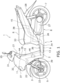
- FIG. 1 is a side view of the straddled vehicle 1.
- the straddled vehicle 1 according to the present embodiment is a scooter-type vehicle.
- the straddled vehicle 1 includes a vehicle body frame 2, a steering device 3, a vehicle body cover 4, a front wheel 5, a seat 6, a rear wheel 7, a power unit 8, and a fuel tank 9.
- the front-rear, up-down, and left-right directions of the straddled vehicle 1 are the front-back, left-right, and up-down directions as seen from a rider on the straddled vehicle 1.
- connection includes not only a direct connection but also an indirect connection. Further, the “connection” is not limited to the fact that separate members are fixed to each other, but also includes the fact that a plurality of parts of an integrated member are continuous.
- FIG. 2 is a perspective view of the vehicle body frame 2 and a fuel system.
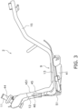
- FIG. 3 is a side view of the vehicle body frame 2 and the fuel system.
- the vehicle body frame 2 includes a head pipe 11, a down frame 12, a first lower frame 13, a second lower frame 14, a first rear frame 15, and a second rear frame 16.
- the head pipe 11 is inclined rearward and upward.
- the down frame 12 extends downward from the head pipe 11.
- the first lower frame 13 and the second lower frame 14 are connected to the lower portion of the down frame 12.
- the first lower frame 13 extends leftward and rearward from the down frame 12.
- the second lower frame 14 extends rightward and rearward from the down frame 12.
- the first rear frame 15 extends rearward and upward from the first lower frame 13.
- the second rear frame 16 extends rearward and upward from the second lower frame 14.
- the steering device 3 is rotatably supported by the head pipe 11.
- the steering device 3 includes a steering shaft 21, an under bracket 22, and a front fork 23.
- the steering shaft 21 is inserted into the head pipe 11.
- the upper portion of the steering shaft 21 is connected to a handle 25.
- the steering shaft 21 is rotatably supported by the head pipe 11 to the left and right.
- the under bracket 22 is connected to the lower portion of the steering shaft 21.
- the upper end of the front fork 23 is connected to the under bracket 22.
- the front wheel 5 is rotatably supported by the front fork 23.
- the vehicle body cover 4 includes a handle cover 31, a front cover 32, a rear cover 33, a lower cover 34, a leg shield 35, and a mud cover 39.
- the handle cover 31 covers the front and the rear of the handle 25.
- a meter panel including a speedometer is attached to the upper surface of the handle cover 31.
- the front cover 32 is disposed in front of the head pipe 11 and the down frame 12.
- a headlight 37 is disposed on the front cover 32.
- the leg shield 35 is disposed behind the front cover 32.
- the leg shield 35 is disposed in front of the seat 6.
- the leg shield 35 is disposed behind the head pipe 11 and the down frame 12.
- the mud cover 39 is disposed behind the front wheel 5 and in front of the leg shield 35.
- the rear cover 33 covers the periphery of the first rear frame 15 and the second rear frame 16. The rear cover 33 is disposed below the seat 6.
- the seat 6 is disposed rearward of the head pipe 11.
- the seat 6 is disposed above the first rear frame 15 and the second rear frame 16.
- a storage box 38 is disposed in the rear cover 33.
- the storage box 38 is disposed below the seat 6.
- the lower cover 34 is disposed between the front cover 32 and the rear cover 33.
- the lower cover 34 covers the periphery of the first lower frame 13 and the second lower frame 14.
- the upper surface of the lower cover 34 includes the footboard 36.
- the footboard 36 is disposed downward and forward of the seat 6.
- the footboard 36 is located behind the leg shield 35.
- the footboard 36 is disposed above the first lower frame 13 and the second lower frame 14. That is, as seen in the vehicle plan view, the footboard 36 overlaps the first lower frame 13 and the second lower frame 14.
- the footboard 36 is disposed between the leg shield 35 and the rear cover 33 in the vehicle front-rear direction.
- the fuel tank 9 is disposed below the footboard 36. That is, as seen in the vehicle plan view, the fuel tank 9 overlaps with the footboard 36.
- the footboard 36 is provided so that the rider can put his/her foot on it.
- the footboard 36 has a flat shape in the vehicle width direction.
- the footboard 36 is not limited to a flat shape.
- a center tunnel portion having a shape protruding upward and extending in the front-rear direction may be provided in the center of the footboard 36.
- the power unit 8 is disposed below the seat 6.
- the power unit 8 is swingably supported by the vehicle body frame 2.
- the power unit 8 rotatably supports the rear wheel 7.
- the rear wheel 7 is supported by the vehicle body frame 2 via the rear suspension 28.
- the power unit 8 includes an engine 26 and a transmission 27.
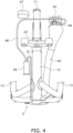
- FIG. 4 is a front view of the vehicle body frame 2 and the fuel system.
- FIG. 5 is a rear view of the vehicle body frame 2 and the fuel system.
- FIG. 6 is a plan view of the vehicle body frame 2 and the fuel system.
- the fuel tank 9 is disposed between the first lower frame 13 and the second lower frame 14 in the vehicle width direction. As shown in FIG. 6 , the fuel tank 9 includes a tank body 41, an inlet pipe 42, and a flange portion 43.
- the tank body 41 has a space for storing fuel inside.
- the inlet pipe 42 is connected to the tank body 41.
- the flange portion 43 protrudes from the tank body 41 in the front-rear and left-right directions.
- the flange portion 43 is fixed to the vehicle body frame 2.
- the straddled vehicle 1 includes a fuel filler port 44, a fuel pipe 45, and a canister 46.
- the fuel filler port 44 is disposed on the leg shield 35.
- the fuel filler port 44 overlaps with the head pipe 11 as seen in the vehicle side view.
- the fuel filler port 44 is disposed to the left of the head pipe 11 as seen in the vehicle rear view.
- the fuel filler port 44 has a tubular shape.
- the fuel filler port 44 includes an opening 441 that opens upward.
- a lid (not shown) that is configured to open and close the opening 441 is attached to the fuel filler port 44.
- the fuel pipe 45 connects the fuel filler port 44 and the fuel tank 9.
- the fuel pipe 45 is disposed to the left of the down frame 12 as seen in the vehicle rear view.
- the fuel pipe 45 is connected to the lower end of the fuel filler port 44.
- the fuel pipe 45 extends downward from the fuel filler port 44.
- the fuel pipe 45 is at least partially disposed behind the front wheel 5.
- the fuel pipe 45 is at least partially located between the mud cover 39 and the leg shield 35.
- the fuel pipe 45 is at least partially located between the front cover 32 and the leg shield 35.
- the fuel pipe 45 is connected to the inlet pipe 42 of the fuel tank 9.
- the fuel pipe 45 extends forward and upward from the fuel tank 9 and extends upward along the down frame 12.
- the canister 46 collects the vaporized fuel gas in the fuel tank 9 or the fuel pipe 45.
- the canister 46 is disposed between the front cover 32 and the leg shield 35.
- the canister 46 has a tubular shape.
- the shape of the canister 46 is not limited to the tubular shape, and may be another shape.
- the central axis of the canister 46 extends in the vertical direction.
- the canister 46 is disposed on the opposite side to the fuel filler port 44 and the fuel pipe 45 in the vehicle width direction with respect to the down frame 12.
- the fuel pipe 45 is disposed to the left of the down frame 12 as seen in the vehicle rear view. Therefore, the canister 46 is disposed to the right of the down frame 12 as seen in the vehicle rear view.
- the down frame 12 is disposed between the fuel pipe 45 and the canister 46 in the vehicle width direction.
- the canister 46 is disposed at a non-overlapping position with the down frame 12 as seen in the vehicle rear view.
- the canister 46 is disposed higher than the footboard 36 as seen in the vehicle side view.
- the lower end of the canister 46 is located higher than the footboard 36.
- the lower end of the canister 46 is located higher than the fuel tank 9.
- the canister 46 is disposed lower than the fuel filler port 44.
- the canister 46 is disposed lower than the under bracket 22.
- the canister 46 is at least partially located forward of the fuel tank 9.
- the canister 46 is disposed forward of the front end of the fuel tank 9.
- the canister 46 is disposed at a non-overlapping position with the fuel tank 9 as seen in the vehicle plan view.
- the straddled vehicle 1 includes a main switch 47.
- the main switch 47 includes, for example, a start switch for the power unit 8.
- the main switch 47 is disposed on the same side as the canister 46 in the vehicle width direction with respect to the down frame 12 as seen in the vehicle rear view. That is, the main switch 47 is disposed to the right of the down frame 12 as seen in the vehicle rear view.
- the canister 46 is disposed lower than the main switch 47 as seen in the vehicle rear view. As seen in the vehicle rear view, the canister 46 is at least partially located inward in the vehicle width direction with respect to the main switch 47. As seen in the vehicle rear view, the canister 46 is at least partially located inward in the vehicle width direction from the outer lateral end of the main switch 47.
- the canister 46 is disposed higher than the first lower frame 13 and the second lower frame 14. As shown in FIG. 3 , as seen in the vehicle side view, the canister 46 at least partially overlaps with the fuel pipe 45. As seen in the vehicle side view, the canister 46 is located forward of the rear edge 451 of the fuel pipe 45. As seen in the vehicle side view, the canister 46 at least partially overlaps with the down frame 12. The canister 46 is disposed at a non-overlapping position with the down frame 12 as seen in the vehicle rear view. The canister 46 is disposed at a non-overlapping position with the fuel pipe 45 as seen in the vehicle rear view. The canister 46 is disposed at a non-overlapping position with the under bracket 22 as seen in the vehicle rear view.
- the straddled vehicle 1 includes a charge tube 48.
- the charge tube 48 connects the fuel pipe 45 and the canister 46.
- the charge tube 48 is disposed so as to pass in front of the head pipe 11. As seen in the vehicle front view, the charge tube 48 overlaps with the head pipe 11.
- the charge tube 48 is disposed over the right side and the left side of the head pipe 11.
- the charge tube 48 is disposed over the right side and the left side of the down frame 12.
- the charge tube 48 is disposed so as to pass between the head pipe 11 and the main switch 47 in the vehicle width direction.
- the fuel filler port 44 includes a charge tube connector 49.
- the charge tube 48 is connected to the charge tube connector 49.
- the charge tube connector 49 may be included in the fuel pipe 45. As seen in the vehicle side view, the charge tube connector 49 is disposed higher than the upper end of the under bracket 22.
- the charge tube 48 extends forward and upward from the charge tube connector 49.
- the charge tube 48 is at least partially located higher than the charge tube connector 49. As seen in the vehicle front view, the charge tube 48 overlaps with the head pipe 11 at a position higher than the lower end of the fuel filler port 44.
- the straddled vehicle 1 includes a purge tube 51.
- the purge tube 51 is connected to the canister 46.
- the purge tube 51 extends downward from the canister 46 along the down frame 12.
- the purge tube 51 is disposed from a position rightward of the down frame 12 to a position leftward of the down frame 12. As seen in the vehicle front view, the purge tube 51 overlaps with the down frame 12.
- the purge tube 51 extends rearward along the first lower frame 13 from a left position of the down frame 12.
- the canister 46 is disposed higher than the footboard 36 in the vehicle side view. Therefore, it is possible to suppress the water intrusion of the canister 46.
- the fuel filler port 44 and the fuel pipe 45 are disposed to the left of the down frame 12, and the canister 46 is disposed to the right of the down frame 12. Therefore, it is possible to easily provide a space for arranging the canister 46 between the front cover 32 and the leg shield 35. As a result, it is possible to suppress the water intrusion of the canister 46, the deterioration of the rider's comfort, and the interference with the movable part such as the under bracket 22 while suppressing the increase in size of the vehicle.
- the charge tube 48 is located over the position rightward of the down frame 12 and the position leftward of the down frame 12. In this case, the charge tube 48 and the movable part are likely to interfere with each other.
- the charge tube connector 49 is disposed higher than the upper end of the under bracket 22 as seen in the vehicle side view. Therefore, the charge tube 48 can be easily disposed while avoiding interference with the movable part such as the under bracket 22.
- the charge tube 48 is disposed so as to pass in front of the head pipe 11. Therefore, the charge tube 48 can be disposed while avoiding interference with the movable part such as the under bracket 22.
- the main switch 47 is disposed to the right of the down frame 12 in the same manner as the canister 46 as seen in the vehicle rear view.
- the canister 46 is disposed lower than the main switch 47 as seen in the vehicle rear view. Therefore, it is possible to prevent the straddled vehicle 1 from becoming larger in the vehicle width direction. Further, the main switch 47 is smaller in the vertical direction than the fuel pipe 45. Therefore, the main switch 47 and the canister 46 can be compactly disposed in the vertical direction.
- the canister 46 is at least partially located inward in the vehicle width direction with respect to the main switch 47. Therefore, it is possible to prevent the straddled vehicle 1 from becoming larger in the vehicle width direction.
- the charge tube 48 is disposed so as to pass between the head pipe 11 and the main switch 47 in the vehicle width direction. Therefore, the charge tube 48 can be disposed compactly while avoiding interference with the main switch 47.
- the canister 46 at least partially overlaps with the fuel pipe 45. Therefore, as compared with the case where the canister 46 is disposed away from the fuel pipe 45 in the front-rear direction, it is possible to suppress the protrusion of the leg shield 35 rearward. As a result, the rider's footrest space can be expanded, so that the comfort can be improved.
- the canister 46 at least partially overlaps with the down frame 12. Therefore, as compared with the case where the canister 46 is disposed away from the down frame 12 in the front-rear direction, it is possible to suppress the protrusion of the leg shield 35 rearward. As a result, the rider's footrest space can be expanded, so that the comfort can be improved.
- the canister 46 is disposed forward of the front end of the fuel tank 9.
- the canister 46 is disposed at a non-overlapping position with the fuel tank 9 as seen in the vehicle plan view. Therefore, as seen in the vehicle plan view, the position of the footboard 36 is suppressed to be higher than that in the case where the canister 46 is disposed at a position overlapping the fuel tank 9. Thereby, the rider's comfort can be improved.
- the charge tube 48 is at least partially located higher than the lower end of the fuel filler port 44. Therefore, the inflow of fuel from the fuel filler port 44 or the fuel pipe 45 to the canister 46 can be suppressed without adding a member such as a valve. For example, in a case where the straddled vehicle 1 leans while the fuel tank 9 is full of fuel, the fuel may reach a position near the fuel filler port 44. Even in such a case, by arranging the charge tube 48 as described above, the inflow of fuel into the canister 46 can be suppressed.
- the charge tube 48 may extend upward from the charge tube connector 49.
- the charge tube 48 may overlap with the head pipe 11 at a position higher than the lower end of the fuel filler port 44 as seen in the vehicle front view. In this case, the inflow of fuel from the fuel filler port 44 or the fuel pipe 45 to the canister 46 can be suppressed without adding a member such as a valve.
- the structure of the vehicle body frame 2 is not limited to that of the above embodiment and may be modified.
- the shape or arrangement of the head pipe 11, the down frame 12, the first lower frame 13, the second lower frame 14, the first rear frame 15, or the second rear frame 16 may be changed.
- the shape or arrangement of the fuel pipe 45, the fuel filler port 44, the canister 46, or the main switch 47 may be changed.
- the fuel pipe 45 and the fuel filler port 44 may be disposed upside down from the above embodiment.
- the canister 46 may be disposed upside down from the above embodiment.
- the main switch 47 may be disposed upside down from the above embodiment.
- the fuel pipe 45 may be disposed to the left or right of the down frame 12, and the other part of the fuel pipe 45 may overlap the down frame 12.
- the canister 46 may be entirely located forward of the fuel tank 9. As seen in the vehicle rear view, only a part of the canister 46 may be located inward in the vehicle width direction with respect to the main switch 47.
- the canister 46 may entirely overlap the fuel pipe 45 as seen in the vehicle side view. Alternatively, the canister 46 may be disposed at a non-overlapping position with the fuel pipe 45 as seen in the vehicle side view. Alternatively, the canister 46 may be disposed at a non-overlapping position with the down frame 12 as seen in the vehicle side view. The canister 46 may at least partially overlap the down frame 12 as seen in the vehicle rear view.
- the charge tube 48 may be located lower than the lower end of the fuel filler port 44.
- a straddled vehicle including a canister
Landscapes
- Engineering & Computer Science (AREA)
- Mechanical Engineering (AREA)
- Automatic Cycles, And Cycles In General (AREA)
Claims (10)
- Spreizsitz-Fahrzeug (1), das umfasst:ein Steuerrohr (11);ein Unterrohr (12), das sich von dem Steuerrohr (11) nach unten erstreckt;eine Lenkwelle (21), die über das Steuerrohr (11) drehbar gelagert ist;eine untere Gabelbrücke (22), die mit der Lenkwelle (21) verbunden ist;eine Vorderradgabel (23), die mit der unteren Gabelbrücke (22) verbunden ist;ein Vorderrad (5), das über die Vorderradgabel (23) drehbar gelagert ist;einen Sitz (6), der hinter dem Steuerrohr (11) angeordnet ist;eine vordere Verkleidung (32), die vor dem Steuerrohr (11) und dem Unterrohr (12) angeordnet ist;einen Beinschutz (35), der hinter der vorderen Verkleidung (32) und vor dem Sitz (6) angeordnet ist,ein Trittbrett (36), das hinter dem Beinschutz (35) sowie vor und unter dem Sitz (6) angeordnet ist;einen Kraftstofftank (9), der unter dem Trittbrett (36) angeordnet ist;einen Kraftstoffeinfüllstutzen (44), der an dem Beinschutz (35) angeordnet ist;eine Kraftstoffleitung (45), die wenigstens teilweise zwischen der vorderen Verkleidung (32) und dem Beinschutz (35) angeordnet ist und den Kraftstoffeinfüllstutzen (44) mit dem Kraftstofftank (9) verbindet;einen Behälter (46), der zwischen der vorderen Verkleidung (32) und dem Beinschutz (35) angeordnet ist und in dem Kraftstofftank (9) oder in der Kraftstoffleitung (45) verdampftes Kraftstoffgas auffängt; sowieein Zuleitrohr (48), das die Kraftstoffleitung (45) und den Behälter (46) verbindet,wobeiwenigstens ein Teil der Kraftstoffleitung (45) sowie der Kraftstoffeinfüllstutzen (44), in einer Fahrzeug-Hinteransicht gesehen, links oder rechts von dem Unterrohr (12) angeordnet sind,der Behälter (46), in einer Fahrzeug-Seitenansicht gesehen, höher angeordnet ist als das Trittbrett (36),der Behälter (46) sich wenigstens teilweise vor dem Kraftstofftank (9) befindet, undein Zuleitrohr-Verbinder (49), in der Fahrzeug-Seitenansicht gesehen, höher angeordnet ist als ein oberes Ende der unteren Gabelbrücke (22), dadurch gekennzeichnet, dass der Behälter in einer Fahrzeug-Breitenrichtung an einer in Bezug auf das Unterrohr dem Kraftstoffeinfüllstutzen und der Kraftstoffleitung gegenüberliegenden Seite angeordnet ist, und das Zuleitrohr über einer rechten Seite und einer linken Seite des Unterrohrs angeordnet ist, wobei die Kraftstoffleitung oder der Kraftstoffeinfüllstutzen den Zuleitrohr-Verbinder einschließt, mit dem das Zuleitrohr verbunden ist.
- Spreizsitz-Fahrzeug nach Anspruch 1, wobei
das Zuleitrohr (48) so angeordnet ist, dass es vor dem Steuerrohr (11) verläuft. - Spreizsitz Fahrzeug nach Anspruch 1 oder 2, in das des Weiteren umfasst:einen Hauptschalter (47), der, in der Fahrzeug-Hinteransicht gesehen, an der gleichen Seite in der Fahrzeug-Breitenrichtung in Bezug auf das Unterrohr (12) angeordnet ist wie der Behälter (46), wobeider Behälter (46), in der Fahrzeug-Hinteransicht gesehen, niedriger angeordnet ist als der Hauptschalter (47).
- Spreizsitz-Fahrzeug nach Anspruch 3, wobei
der Behälter (46), in der Fahrzeug-Hinteransicht gesehen, in Bezug auf den Hauptschalter (47) in der Fahrzeug-Breitenrichtung wenigstens teilweise innenliegend angeordnet ist. - Spreizsitz-Fahrzeug nach Anspruch 3 oder 4, wobei
das Zuleitrohr (48) in der Fahrzeug-Breitenrichtung so angeordnet ist, dass es zwischen dem Steuerrohr (11) und dem Hauptschalter (47) verläuft. - Spreizsitz-Fahrzeug nach einem der Ansprüche 1 bis 5, wobei
sich der Behälter (46), in der Fahrzeug-Seitenansicht gesehen, wenigstens teilweise mit der Kraftstoffleitung (45) überlappt. - Spreizsitz-Fahrzeug nach einem der Ansprüche 1 bis 6, wobei
sich der Behälter (46), in der Fahrzeug-Seitenansicht gesehen, wenigstens teilweise mit dem Unterrohr (12) überlappt. - Spreizsitz-Fahrzeug nach einem der Ansprüche 1 bis 7, wobeider Behälter (46) vor einem vorderen Ende des Kraftstofftanks (9) angeordnet ist; undder Behälter (46), in einer Fahrzeug-Draufsicht gesehen, an einer Position angeordnet ist, an der er sich nicht mit dem Kraftstofftank (9) überlappt.
- Spreizsitz-Fahrzeug nach einem der Ansprüche 1 bis 8, wobei
das Zuleitrohr (48) wenigstens teilweise höher angeordnet ist als ein unteres Ende des Kraftstoffeinfüllstutzens (44). - Spreizsitz-Fahrzeug nach einem der Ansprüche 1 bis 9, wobei
sich das Zuleitrohr (46) von dem Zuleitrohr-Verbinder (49) nach oben erstreckt und sich, in einer Fahrzeug-Vorderansicht gesehen, mit dem Steuerrohr (11) an einer Position überlappt, die höher liegt als das untere Ende des Kraftstoffeinfüllstutzens (44).
Applications Claiming Priority (2)
| Application Number | Priority Date | Filing Date | Title |
|---|---|---|---|
| JP2020030103A JP2021133758A (ja) | 2020-02-26 | 2020-02-26 | 鞍乗型車両 |
| PCT/JP2021/007077 WO2021172422A1 (ja) | 2020-02-26 | 2021-02-25 | 鞍乗型車両 |
Publications (3)
| Publication Number | Publication Date |
|---|---|
| EP4112430A1 EP4112430A1 (de) | 2023-01-04 |
| EP4112430A4 EP4112430A4 (de) | 2024-03-06 |
| EP4112430B1 true EP4112430B1 (de) | 2024-10-09 |
Family
ID=77491510
Family Applications (1)
| Application Number | Title | Priority Date | Filing Date |
|---|---|---|---|
| EP21760524.5A Active EP4112430B1 (de) | 2020-02-26 | 2021-02-25 | Sattelfahrzeug |
Country Status (4)
| Country | Link |
|---|---|
| EP (1) | EP4112430B1 (de) |
| JP (1) | JP2021133758A (de) |
| TW (1) | TWI764595B (de) |
| WO (1) | WO2021172422A1 (de) |
Families Citing this family (2)
| Publication number | Priority date | Publication date | Assignee | Title |
|---|---|---|---|---|
| US20240359954A1 (en) | 2021-08-19 | 2024-10-31 | Tadano Ltd. | Loading type truck crane |
| CN121590672A (zh) * | 2024-08-15 | 2026-03-03 | 雅马哈发动机株式会社 | 跨骑型车辆 |
Family Cites Families (14)
| Publication number | Priority date | Publication date | Assignee | Title |
|---|---|---|---|---|
| JP2003237663A (ja) | 2001-11-20 | 2003-08-27 | Yamaha Motor Co Ltd | 車両用燃料系構造 |
| JP4152733B2 (ja) * | 2001-12-13 | 2008-09-17 | ヤマハ発動機株式会社 | スクータ型車両用燃料系構造 |
| JP3978336B2 (ja) * | 2001-12-20 | 2007-09-19 | ヤマハ発動機株式会社 | 自動二輪車のエアクリーナ防水構造 |
| JP3978335B2 (ja) * | 2001-12-20 | 2007-09-19 | ヤマハ発動機株式会社 | スクータ型自動二輪車の新気取入構造 |
| EP2176115B1 (de) * | 2008-08-01 | 2011-04-27 | Yamaha Hatsudoki Kabushiki Kaisha | Rollerartiges fahrzeug |
| ES2384915T3 (es) * | 2008-08-01 | 2012-07-13 | Yamaha Hatsudoki Kabushiki Kaisha | Vehículo de tipo scooter |
| JP2010215214A (ja) * | 2009-02-19 | 2010-09-30 | Yamaha Motor Co Ltd | スクータ型車両 |
| JP5280273B2 (ja) * | 2009-03-30 | 2013-09-04 | 本田技研工業株式会社 | 鞍乗り型車両のキャニスタの配置構造 |
| JP5719738B2 (ja) * | 2011-09-26 | 2015-05-20 | 本田技研工業株式会社 | スクータ型車両 |
| JP6001892B2 (ja) * | 2012-03-22 | 2016-10-05 | 本田技研工業株式会社 | 鞍乗り型車両のフレーム構造 |
| JP5889685B2 (ja) * | 2012-03-22 | 2016-03-22 | 本田技研工業株式会社 | 鞍乗り型車両のキャニスター配置構造 |
| CN106163908B (zh) * | 2014-03-31 | 2019-01-08 | 本田技研工业株式会社 | 用于摩托车的滤罐安装结构 |
| JP2016016736A (ja) * | 2014-07-08 | 2016-02-01 | ヤマハ発動機株式会社 | スクータ型車両 |
| TWM568809U (zh) * | 2018-03-20 | 2018-10-21 | 三陽工業股份有限公司 | 機車活性碳罐設置構造 |
-
2020
- 2020-02-26 JP JP2020030103A patent/JP2021133758A/ja active Pending
-
2021
- 2021-02-25 WO PCT/JP2021/007077 patent/WO2021172422A1/ja not_active Ceased
- 2021-02-25 EP EP21760524.5A patent/EP4112430B1/de active Active
- 2021-02-26 TW TW110106959A patent/TWI764595B/zh active
Also Published As
| Publication number | Publication date |
|---|---|
| WO2021172422A1 (ja) | 2021-09-02 |
| TW202132136A (zh) | 2021-09-01 |
| EP4112430A4 (de) | 2024-03-06 |
| TWI764595B (zh) | 2022-05-11 |
| EP4112430A1 (de) | 2023-01-04 |
| JP2021133758A (ja) | 2021-09-13 |
Similar Documents
| Publication | Publication Date | Title |
|---|---|---|
| JP4077173B2 (ja) | スクータ型車両 | |
| JP2918116B2 (ja) | スクータ型自動二,三輪車の燃料供給部構造 | |
| EP2176115B1 (de) | Rollerartiges fahrzeug | |
| EP2167367B1 (de) | Rollerartiges fahrzeug | |
| US6655363B2 (en) | Fuel supply system for vehicle | |
| EP4112430B1 (de) | Sattelfahrzeug | |
| EP2221206B1 (de) | Rollerartiges Fahrzeug | |
| JP5560059B2 (ja) | 鞍乗り型車両 | |
| EP3599149B1 (de) | Grätschsitzfahrzeug | |
| JP5719264B2 (ja) | 鞍乗型車両のキャニスタ配置構造 | |
| EP3190035B1 (de) | Grätschsitzfahrzeug | |
| JP7398414B2 (ja) | 鞍乗り型車両 | |
| EP3889014B1 (de) | Grätschsitzfahrzeug | |
| JP4153803B2 (ja) | 自動二輪車の燃料タンク配置 | |
| EP3636530B1 (de) | Grätschsitzfahrzeug | |
| EP4696595A1 (de) | Grätschsitzfahrzeug | |
| JP3041820B2 (ja) | 自動二,三輪車のハンドルカバー | |
| JP7402849B2 (ja) | 鞍乗り型車両 | |
| JP2013193483A (ja) | 鞍乗型車両 | |
| JP2021160595A (ja) | 鞍乗り型車両 | |
| JP5801142B2 (ja) | 自動二輪車 | |
| TWI716749B (zh) | 跨坐型車輛 | |
| JP2694337B2 (ja) | スクータ型車両 | |
| JP2013193482A (ja) | 鞍乗型車両 | |
| EP4023537B1 (de) | Grätschsitzfahrzeug |
Legal Events
| Date | Code | Title | Description |
|---|---|---|---|
| STAA | Information on the status of an ep patent application or granted ep patent |
Free format text: STATUS: THE INTERNATIONAL PUBLICATION HAS BEEN MADE |
|
| PUAI | Public reference made under article 153(3) epc to a published international application that has entered the european phase |
Free format text: ORIGINAL CODE: 0009012 |
|
| STAA | Information on the status of an ep patent application or granted ep patent |
Free format text: STATUS: REQUEST FOR EXAMINATION WAS MADE |
|
| 17P | Request for examination filed |
Effective date: 20220720 |
|
| AK | Designated contracting states |
Kind code of ref document: A1 Designated state(s): AL AT BE BG CH CY CZ DE DK EE ES FI FR GB GR HR HU IE IS IT LI LT LU LV MC MK MT NL NO PL PT RO RS SE SI SK SM TR |
|
| DAV | Request for validation of the european patent (deleted) | ||
| DAX | Request for extension of the european patent (deleted) | ||
| P01 | Opt-out of the competence of the unified patent court (upc) registered |
Effective date: 20230527 |
|
| A4 | Supplementary search report drawn up and despatched |
Effective date: 20240202 |
|
| RIC1 | Information provided on ipc code assigned before grant |
Ipc: B62K 11/10 20060101ALI20240129BHEP Ipc: B62J 35/00 20060101ALI20240129BHEP Ipc: B62J 37/00 20060101AFI20240129BHEP |
|
| GRAP | Despatch of communication of intention to grant a patent |
Free format text: ORIGINAL CODE: EPIDOSNIGR1 |
|
| STAA | Information on the status of an ep patent application or granted ep patent |
Free format text: STATUS: GRANT OF PATENT IS INTENDED |
|
| INTG | Intention to grant announced |
Effective date: 20240507 |
|
| GRAS | Grant fee paid |
Free format text: ORIGINAL CODE: EPIDOSNIGR3 |
|
| GRAA | (expected) grant |
Free format text: ORIGINAL CODE: 0009210 |
|
| STAA | Information on the status of an ep patent application or granted ep patent |
Free format text: STATUS: THE PATENT HAS BEEN GRANTED |
|
| AK | Designated contracting states |
Kind code of ref document: B1 Designated state(s): AL AT BE BG CH CY CZ DE DK EE ES FI FR GB GR HR HU IE IS IT LI LT LU LV MC MK MT NL NO PL PT RO RS SE SI SK SM TR |
|
| REG | Reference to a national code |
Ref country code: CH Ref legal event code: EP |
|
| REG | Reference to a national code |
Ref country code: DE Ref legal event code: R096 Ref document number: 602021020014 Country of ref document: DE |
|
| REG | Reference to a national code |
Ref country code: IE Ref legal event code: FG4D |
|
| REG | Reference to a national code |
Ref country code: LT Ref legal event code: MG9D |
|
| REG | Reference to a national code |
Ref country code: NL Ref legal event code: MP Effective date: 20241009 |
|
| REG | Reference to a national code |
Ref country code: AT Ref legal event code: MK05 Ref document number: 1730330 Country of ref document: AT Kind code of ref document: T Effective date: 20241009 |
|
| PG25 | Lapsed in a contracting state [announced via postgrant information from national office to epo] |
Ref country code: NL Free format text: LAPSE BECAUSE OF FAILURE TO SUBMIT A TRANSLATION OF THE DESCRIPTION OR TO PAY THE FEE WITHIN THE PRESCRIBED TIME-LIMIT Effective date: 20241009 |
|
| PG25 | Lapsed in a contracting state [announced via postgrant information from national office to epo] |
Ref country code: NL Free format text: LAPSE BECAUSE OF FAILURE TO SUBMIT A TRANSLATION OF THE DESCRIPTION OR TO PAY THE FEE WITHIN THE PRESCRIBED TIME-LIMIT Effective date: 20241009 |
|
| PG25 | Lapsed in a contracting state [announced via postgrant information from national office to epo] |
Ref country code: PT Free format text: LAPSE BECAUSE OF FAILURE TO SUBMIT A TRANSLATION OF THE DESCRIPTION OR TO PAY THE FEE WITHIN THE PRESCRIBED TIME-LIMIT Effective date: 20250210 Ref country code: IS Free format text: LAPSE BECAUSE OF FAILURE TO SUBMIT A TRANSLATION OF THE DESCRIPTION OR TO PAY THE FEE WITHIN THE PRESCRIBED TIME-LIMIT Effective date: 20250209 Ref country code: HR Free format text: LAPSE BECAUSE OF FAILURE TO SUBMIT A TRANSLATION OF THE DESCRIPTION OR TO PAY THE FEE WITHIN THE PRESCRIBED TIME-LIMIT Effective date: 20241009 |
|
| PG25 | Lapsed in a contracting state [announced via postgrant information from national office to epo] |
Ref country code: FI Free format text: LAPSE BECAUSE OF FAILURE TO SUBMIT A TRANSLATION OF THE DESCRIPTION OR TO PAY THE FEE WITHIN THE PRESCRIBED TIME-LIMIT Effective date: 20241009 |
|
| PG25 | Lapsed in a contracting state [announced via postgrant information from national office to epo] |
Ref country code: BG Free format text: LAPSE BECAUSE OF FAILURE TO SUBMIT A TRANSLATION OF THE DESCRIPTION OR TO PAY THE FEE WITHIN THE PRESCRIBED TIME-LIMIT Effective date: 20241009 |
|
| PG25 | Lapsed in a contracting state [announced via postgrant information from national office to epo] |
Ref country code: ES Free format text: LAPSE BECAUSE OF FAILURE TO SUBMIT A TRANSLATION OF THE DESCRIPTION OR TO PAY THE FEE WITHIN THE PRESCRIBED TIME-LIMIT Effective date: 20241009 |
|
| PG25 | Lapsed in a contracting state [announced via postgrant information from national office to epo] |
Ref country code: NO Free format text: LAPSE BECAUSE OF FAILURE TO SUBMIT A TRANSLATION OF THE DESCRIPTION OR TO PAY THE FEE WITHIN THE PRESCRIBED TIME-LIMIT Effective date: 20250109 |
|
| PG25 | Lapsed in a contracting state [announced via postgrant information from national office to epo] |
Ref country code: LV Free format text: LAPSE BECAUSE OF FAILURE TO SUBMIT A TRANSLATION OF THE DESCRIPTION OR TO PAY THE FEE WITHIN THE PRESCRIBED TIME-LIMIT Effective date: 20241009 Ref country code: GR Free format text: LAPSE BECAUSE OF FAILURE TO SUBMIT A TRANSLATION OF THE DESCRIPTION OR TO PAY THE FEE WITHIN THE PRESCRIBED TIME-LIMIT Effective date: 20250110 Ref country code: AT Free format text: LAPSE BECAUSE OF FAILURE TO SUBMIT A TRANSLATION OF THE DESCRIPTION OR TO PAY THE FEE WITHIN THE PRESCRIBED TIME-LIMIT Effective date: 20241009 |
|
| PG25 | Lapsed in a contracting state [announced via postgrant information from national office to epo] |
Ref country code: PL Free format text: LAPSE BECAUSE OF FAILURE TO SUBMIT A TRANSLATION OF THE DESCRIPTION OR TO PAY THE FEE WITHIN THE PRESCRIBED TIME-LIMIT Effective date: 20241009 |
|
| PG25 | Lapsed in a contracting state [announced via postgrant information from national office to epo] |
Ref country code: RS Free format text: LAPSE BECAUSE OF FAILURE TO SUBMIT A TRANSLATION OF THE DESCRIPTION OR TO PAY THE FEE WITHIN THE PRESCRIBED TIME-LIMIT Effective date: 20250109 |
|
| PG25 | Lapsed in a contracting state [announced via postgrant information from national office to epo] |
Ref country code: SM Free format text: LAPSE BECAUSE OF FAILURE TO SUBMIT A TRANSLATION OF THE DESCRIPTION OR TO PAY THE FEE WITHIN THE PRESCRIBED TIME-LIMIT Effective date: 20241009 |
|
| PG25 | Lapsed in a contracting state [announced via postgrant information from national office to epo] |
Ref country code: DK Free format text: LAPSE BECAUSE OF FAILURE TO SUBMIT A TRANSLATION OF THE DESCRIPTION OR TO PAY THE FEE WITHIN THE PRESCRIBED TIME-LIMIT Effective date: 20241009 |
|
| REG | Reference to a national code |
Ref country code: DE Ref legal event code: R097 Ref document number: 602021020014 Country of ref document: DE |
|
| PG25 | Lapsed in a contracting state [announced via postgrant information from national office to epo] |
Ref country code: EE Free format text: LAPSE BECAUSE OF FAILURE TO SUBMIT A TRANSLATION OF THE DESCRIPTION OR TO PAY THE FEE WITHIN THE PRESCRIBED TIME-LIMIT Effective date: 20241009 |
|
| PG25 | Lapsed in a contracting state [announced via postgrant information from national office to epo] |
Ref country code: RO Free format text: LAPSE BECAUSE OF FAILURE TO SUBMIT A TRANSLATION OF THE DESCRIPTION OR TO PAY THE FEE WITHIN THE PRESCRIBED TIME-LIMIT Effective date: 20241009 |
|
| PG25 | Lapsed in a contracting state [announced via postgrant information from national office to epo] |
Ref country code: SK Free format text: LAPSE BECAUSE OF FAILURE TO SUBMIT A TRANSLATION OF THE DESCRIPTION OR TO PAY THE FEE WITHIN THE PRESCRIBED TIME-LIMIT Effective date: 20241009 |
|
| PG25 | Lapsed in a contracting state [announced via postgrant information from national office to epo] |
Ref country code: CZ Free format text: LAPSE BECAUSE OF FAILURE TO SUBMIT A TRANSLATION OF THE DESCRIPTION OR TO PAY THE FEE WITHIN THE PRESCRIBED TIME-LIMIT Effective date: 20241009 |
|
| PLBE | No opposition filed within time limit |
Free format text: ORIGINAL CODE: 0009261 |
|
| STAA | Information on the status of an ep patent application or granted ep patent |
Free format text: STATUS: NO OPPOSITION FILED WITHIN TIME LIMIT |
|
| PG25 | Lapsed in a contracting state [announced via postgrant information from national office to epo] |
Ref country code: SE Free format text: LAPSE BECAUSE OF FAILURE TO SUBMIT A TRANSLATION OF THE DESCRIPTION OR TO PAY THE FEE WITHIN THE PRESCRIBED TIME-LIMIT Effective date: 20241009 |
|
| PG25 | Lapsed in a contracting state [announced via postgrant information from national office to epo] |
Ref country code: MC Free format text: LAPSE BECAUSE OF FAILURE TO SUBMIT A TRANSLATION OF THE DESCRIPTION OR TO PAY THE FEE WITHIN THE PRESCRIBED TIME-LIMIT Effective date: 20241009 |
|
| 26N | No opposition filed |
Effective date: 20250710 |
|
| REG | Reference to a national code |
Ref country code: CH Ref legal event code: PL |
|
| PG25 | Lapsed in a contracting state [announced via postgrant information from national office to epo] |
Ref country code: LU Free format text: LAPSE BECAUSE OF NON-PAYMENT OF DUE FEES Effective date: 20250225 |
|
| PG25 | Lapsed in a contracting state [announced via postgrant information from national office to epo] |
Ref country code: CH Free format text: LAPSE BECAUSE OF NON-PAYMENT OF DUE FEES Effective date: 20250228 |
|
| GBPC | Gb: european patent ceased through non-payment of renewal fee |
Effective date: 20250225 |
|
| REG | Reference to a national code |
Ref country code: BE Ref legal event code: MM Effective date: 20250228 |
|
| PG25 | Lapsed in a contracting state [announced via postgrant information from national office to epo] |
Ref country code: GB Free format text: LAPSE BECAUSE OF NON-PAYMENT OF DUE FEES Effective date: 20250225 |
|
| PG25 | Lapsed in a contracting state [announced via postgrant information from national office to epo] |
Ref country code: BE Free format text: LAPSE BECAUSE OF NON-PAYMENT OF DUE FEES Effective date: 20250228 |
|
| PG25 | Lapsed in a contracting state [announced via postgrant information from national office to epo] |
Ref country code: IE Free format text: LAPSE BECAUSE OF NON-PAYMENT OF DUE FEES Effective date: 20250225 |
|
| PGFP | Annual fee paid to national office [announced via postgrant information from national office to epo] |
Ref country code: DE Payment date: 20260218 Year of fee payment: 6 |
|
| PGFP | Annual fee paid to national office [announced via postgrant information from national office to epo] |
Ref country code: IT Payment date: 20260224 Year of fee payment: 6 |
|
| PGFP | Annual fee paid to national office [announced via postgrant information from national office to epo] |
Ref country code: FR Payment date: 20260219 Year of fee payment: 6 |