EP4105014B1 - Joining structure, joining method, exterior body for wire harness, and wire harness - Google Patents
Joining structure, joining method, exterior body for wire harness, and wire harness Download PDFInfo
- Publication number
- EP4105014B1 EP4105014B1 EP21776247.5A EP21776247A EP4105014B1 EP 4105014 B1 EP4105014 B1 EP 4105014B1 EP 21776247 A EP21776247 A EP 21776247A EP 4105014 B1 EP4105014 B1 EP 4105014B1
- Authority
- EP
- European Patent Office
- Prior art keywords
- resin
- joining
- wire harness
- hot
- joining structure
- Prior art date
- Legal status (The legal status is an assumption and is not a legal conclusion. Google has not performed a legal analysis and makes no representation as to the accuracy of the status listed.)
- Active
Links
Images




Classifications
-
- B—PERFORMING OPERATIONS; TRANSPORTING
- B32—LAYERED PRODUCTS
- B32B—LAYERED PRODUCTS, i.e. PRODUCTS BUILT-UP OF STRATA OF FLAT OR NON-FLAT, e.g. CELLULAR OR HONEYCOMB, FORM
- B32B3/00—Layered products comprising a layer with external or internal discontinuities or unevennesses, or a layer of non-planar shape; Layered products comprising a layer having particular features of form
- B32B3/26—Layered products comprising a layer with external or internal discontinuities or unevennesses, or a layer of non-planar shape; Layered products comprising a layer having particular features of form characterised by a particular shape of the outline of the cross-section of a continuous layer; characterised by a layer with cavities or internal voids ; characterised by an apertured layer
- B32B3/266—Layered products comprising a layer with external or internal discontinuities or unevennesses, or a layer of non-planar shape; Layered products comprising a layer having particular features of form characterised by a particular shape of the outline of the cross-section of a continuous layer; characterised by a layer with cavities or internal voids ; characterised by an apertured layer characterised by an apertured layer, the apertures going through the whole thickness of the layer, e.g. expanded metal, perforated layer, slit layer regular cells B32B3/12
-
- B—PERFORMING OPERATIONS; TRANSPORTING
- B29—WORKING OF PLASTICS; WORKING OF SUBSTANCES IN A PLASTIC STATE IN GENERAL
- B29C—SHAPING OR JOINING OF PLASTICS; SHAPING OF MATERIAL IN A PLASTIC STATE, NOT OTHERWISE PROVIDED FOR; AFTER-TREATMENT OF THE SHAPED PRODUCTS, e.g. REPAIRING
- B29C65/00—Joining or sealing of preformed parts, e.g. welding of plastics materials; Apparatus therefor
- B29C65/02—Joining or sealing of preformed parts, e.g. welding of plastics materials; Apparatus therefor by heating, with or without pressure
- B29C65/08—Joining or sealing of preformed parts, e.g. welding of plastics materials; Apparatus therefor by heating, with or without pressure using ultrasonic vibrations
-
- B—PERFORMING OPERATIONS; TRANSPORTING
- B29—WORKING OF PLASTICS; WORKING OF SUBSTANCES IN A PLASTIC STATE IN GENERAL
- B29C—SHAPING OR JOINING OF PLASTICS; SHAPING OF MATERIAL IN A PLASTIC STATE, NOT OTHERWISE PROVIDED FOR; AFTER-TREATMENT OF THE SHAPED PRODUCTS, e.g. REPAIRING
- B29C65/00—Joining or sealing of preformed parts, e.g. welding of plastics materials; Apparatus therefor
- B29C65/74—Joining or sealing of preformed parts, e.g. welding of plastics materials; Apparatus therefor by welding and severing, or by joining and severing, the severing being performed in the area to be joined, next to the area to be joined, in the joint area or next to the joint area
- B29C65/743—Joining or sealing of preformed parts, e.g. welding of plastics materials; Apparatus therefor by welding and severing, or by joining and severing, the severing being performed in the area to be joined, next to the area to be joined, in the joint area or next to the joint area using the same tool for both joining and severing, said tool being monobloc or formed by several parts mounted together and forming a monobloc
- B29C65/7437—Joining or sealing of preformed parts, e.g. welding of plastics materials; Apparatus therefor by welding and severing, or by joining and severing, the severing being performed in the area to be joined, next to the area to be joined, in the joint area or next to the joint area using the same tool for both joining and severing, said tool being monobloc or formed by several parts mounted together and forming a monobloc the tool being a perforating tool
-
- B—PERFORMING OPERATIONS; TRANSPORTING
- B29—WORKING OF PLASTICS; WORKING OF SUBSTANCES IN A PLASTIC STATE IN GENERAL
- B29C—SHAPING OR JOINING OF PLASTICS; SHAPING OF MATERIAL IN A PLASTIC STATE, NOT OTHERWISE PROVIDED FOR; AFTER-TREATMENT OF THE SHAPED PRODUCTS, e.g. REPAIRING
- B29C65/00—Joining or sealing of preformed parts, e.g. welding of plastics materials; Apparatus therefor
- B29C65/74—Joining or sealing of preformed parts, e.g. welding of plastics materials; Apparatus therefor by welding and severing, or by joining and severing, the severing being performed in the area to be joined, next to the area to be joined, in the joint area or next to the joint area
- B29C65/743—Joining or sealing of preformed parts, e.g. welding of plastics materials; Apparatus therefor by welding and severing, or by joining and severing, the severing being performed in the area to be joined, next to the area to be joined, in the joint area or next to the joint area using the same tool for both joining and severing, said tool being monobloc or formed by several parts mounted together and forming a monobloc
- B29C65/7443—Joining or sealing of preformed parts, e.g. welding of plastics materials; Apparatus therefor by welding and severing, or by joining and severing, the severing being performed in the area to be joined, next to the area to be joined, in the joint area or next to the joint area using the same tool for both joining and severing, said tool being monobloc or formed by several parts mounted together and forming a monobloc by means of ultrasonic vibrations
-
- B—PERFORMING OPERATIONS; TRANSPORTING
- B29—WORKING OF PLASTICS; WORKING OF SUBSTANCES IN A PLASTIC STATE IN GENERAL
- B29C—SHAPING OR JOINING OF PLASTICS; SHAPING OF MATERIAL IN A PLASTIC STATE, NOT OTHERWISE PROVIDED FOR; AFTER-TREATMENT OF THE SHAPED PRODUCTS, e.g. REPAIRING
- B29C65/00—Joining or sealing of preformed parts, e.g. welding of plastics materials; Apparatus therefor
- B29C65/82—Testing the joint
- B29C65/8207—Testing the joint by mechanical methods
- B29C65/8215—Tensile tests
-
- B—PERFORMING OPERATIONS; TRANSPORTING
- B29—WORKING OF PLASTICS; WORKING OF SUBSTANCES IN A PLASTIC STATE IN GENERAL
- B29C—SHAPING OR JOINING OF PLASTICS; SHAPING OF MATERIAL IN A PLASTIC STATE, NOT OTHERWISE PROVIDED FOR; AFTER-TREATMENT OF THE SHAPED PRODUCTS, e.g. REPAIRING
- B29C65/00—Joining or sealing of preformed parts, e.g. welding of plastics materials; Apparatus therefor
- B29C65/82—Testing the joint
- B29C65/8207—Testing the joint by mechanical methods
- B29C65/8223—Peel tests
-
- B—PERFORMING OPERATIONS; TRANSPORTING
- B29—WORKING OF PLASTICS; WORKING OF SUBSTANCES IN A PLASTIC STATE IN GENERAL
- B29C—SHAPING OR JOINING OF PLASTICS; SHAPING OF MATERIAL IN A PLASTIC STATE, NOT OTHERWISE PROVIDED FOR; AFTER-TREATMENT OF THE SHAPED PRODUCTS, e.g. REPAIRING
- B29C65/00—Joining or sealing of preformed parts, e.g. welding of plastics materials; Apparatus therefor
- B29C65/82—Testing the joint
- B29C65/8253—Testing the joint by the use of waves or particle radiation, e.g. visual examination, scanning electron microscopy, or X-rays
-
- B—PERFORMING OPERATIONS; TRANSPORTING
- B29—WORKING OF PLASTICS; WORKING OF SUBSTANCES IN A PLASTIC STATE IN GENERAL
- B29C—SHAPING OR JOINING OF PLASTICS; SHAPING OF MATERIAL IN A PLASTIC STATE, NOT OTHERWISE PROVIDED FOR; AFTER-TREATMENT OF THE SHAPED PRODUCTS, e.g. REPAIRING
- B29C66/00—General aspects of processes or apparatus for joining preformed parts
- B29C66/01—General aspects dealing with the joint area or with the area to be joined
- B29C66/05—Particular design of joint configurations
- B29C66/10—Particular design of joint configurations particular design of the joint cross-sections
- B29C66/11—Joint cross-sections comprising a single joint-segment, i.e. one of the parts to be joined comprising a single joint-segment in the joint cross-section
- B29C66/112—Single lapped joints
- B29C66/1122—Single lap to lap joints, i.e. overlap joints
-
- B—PERFORMING OPERATIONS; TRANSPORTING
- B29—WORKING OF PLASTICS; WORKING OF SUBSTANCES IN A PLASTIC STATE IN GENERAL
- B29C—SHAPING OR JOINING OF PLASTICS; SHAPING OF MATERIAL IN A PLASTIC STATE, NOT OTHERWISE PROVIDED FOR; AFTER-TREATMENT OF THE SHAPED PRODUCTS, e.g. REPAIRING
- B29C66/00—General aspects of processes or apparatus for joining preformed parts
- B29C66/01—General aspects dealing with the joint area or with the area to be joined
- B29C66/05—Particular design of joint configurations
- B29C66/20—Particular design of joint configurations particular design of the joint lines, e.g. of the weld lines
- B29C66/21—Particular design of joint configurations particular design of the joint lines, e.g. of the weld lines said joint lines being formed by a single dot or dash or by several dots or dashes, i.e. spot joining or spot welding
-
- B—PERFORMING OPERATIONS; TRANSPORTING
- B29—WORKING OF PLASTICS; WORKING OF SUBSTANCES IN A PLASTIC STATE IN GENERAL
- B29C—SHAPING OR JOINING OF PLASTICS; SHAPING OF MATERIAL IN A PLASTIC STATE, NOT OTHERWISE PROVIDED FOR; AFTER-TREATMENT OF THE SHAPED PRODUCTS, e.g. REPAIRING
- B29C66/00—General aspects of processes or apparatus for joining preformed parts
- B29C66/40—General aspects of joining substantially flat articles, e.g. plates, sheets or web-like materials; Making flat seams in tubular or hollow articles; Joining single elements to substantially flat surfaces
- B29C66/41—Joining substantially flat articles ; Making flat seams in tubular or hollow articles
-
- B—PERFORMING OPERATIONS; TRANSPORTING
- B29—WORKING OF PLASTICS; WORKING OF SUBSTANCES IN A PLASTIC STATE IN GENERAL
- B29C—SHAPING OR JOINING OF PLASTICS; SHAPING OF MATERIAL IN A PLASTIC STATE, NOT OTHERWISE PROVIDED FOR; AFTER-TREATMENT OF THE SHAPED PRODUCTS, e.g. REPAIRING
- B29C66/00—General aspects of processes or apparatus for joining preformed parts
- B29C66/70—General aspects of processes or apparatus for joining preformed parts characterised by the composition, physical properties or the structure of the material of the parts to be joined; Joining with non-plastics material
- B29C66/71—General aspects of processes or apparatus for joining preformed parts characterised by the composition, physical properties or the structure of the material of the parts to be joined; Joining with non-plastics material characterised by the composition of the plastics material of the parts to be joined
- B29C66/712—General aspects of processes or apparatus for joining preformed parts characterised by the composition, physical properties or the structure of the material of the parts to be joined; Joining with non-plastics material characterised by the composition of the plastics material of the parts to be joined the composition of one of the parts to be joined being different from the composition of the other part
-
- B—PERFORMING OPERATIONS; TRANSPORTING
- B29—WORKING OF PLASTICS; WORKING OF SUBSTANCES IN A PLASTIC STATE IN GENERAL
- B29C—SHAPING OR JOINING OF PLASTICS; SHAPING OF MATERIAL IN A PLASTIC STATE, NOT OTHERWISE PROVIDED FOR; AFTER-TREATMENT OF THE SHAPED PRODUCTS, e.g. REPAIRING
- B29C66/00—General aspects of processes or apparatus for joining preformed parts
- B29C66/70—General aspects of processes or apparatus for joining preformed parts characterised by the composition, physical properties or the structure of the material of the parts to be joined; Joining with non-plastics material
- B29C66/72—General aspects of processes or apparatus for joining preformed parts characterised by the composition, physical properties or the structure of the material of the parts to be joined; Joining with non-plastics material characterised by the structure of the material of the parts to be joined
- B29C66/727—General aspects of processes or apparatus for joining preformed parts characterised by the composition, physical properties or the structure of the material of the parts to be joined; Joining with non-plastics material characterised by the structure of the material of the parts to be joined being porous, e.g. foam
-
- B—PERFORMING OPERATIONS; TRANSPORTING
- B29—WORKING OF PLASTICS; WORKING OF SUBSTANCES IN A PLASTIC STATE IN GENERAL
- B29C—SHAPING OR JOINING OF PLASTICS; SHAPING OF MATERIAL IN A PLASTIC STATE, NOT OTHERWISE PROVIDED FOR; AFTER-TREATMENT OF THE SHAPED PRODUCTS, e.g. REPAIRING
- B29C66/00—General aspects of processes or apparatus for joining preformed parts
- B29C66/70—General aspects of processes or apparatus for joining preformed parts characterised by the composition, physical properties or the structure of the material of the parts to be joined; Joining with non-plastics material
- B29C66/73—General aspects of processes or apparatus for joining preformed parts characterised by the composition, physical properties or the structure of the material of the parts to be joined; Joining with non-plastics material characterised by the intensive physical properties of the material of the parts to be joined, by the optical properties of the material of the parts to be joined, by the extensive physical properties of the parts to be joined, by the state of the material of the parts to be joined or by the material of the parts to be joined being a thermoplastic or a thermoset
- B29C66/731—General aspects of processes or apparatus for joining preformed parts characterised by the composition, physical properties or the structure of the material of the parts to be joined; Joining with non-plastics material characterised by the intensive physical properties of the material of the parts to be joined, by the optical properties of the material of the parts to be joined, by the extensive physical properties of the parts to be joined, by the state of the material of the parts to be joined or by the material of the parts to be joined being a thermoplastic or a thermoset characterised by the intensive physical properties of the material of the parts to be joined
- B29C66/7311—Thermal properties
- B29C66/73115—Melting point
- B29C66/73116—Melting point of different melting point, i.e. the melting point of one of the parts to be joined being different from the melting point of the other part
-
- B—PERFORMING OPERATIONS; TRANSPORTING
- B29—WORKING OF PLASTICS; WORKING OF SUBSTANCES IN A PLASTIC STATE IN GENERAL
- B29C—SHAPING OR JOINING OF PLASTICS; SHAPING OF MATERIAL IN A PLASTIC STATE, NOT OTHERWISE PROVIDED FOR; AFTER-TREATMENT OF THE SHAPED PRODUCTS, e.g. REPAIRING
- B29C66/00—General aspects of processes or apparatus for joining preformed parts
- B29C66/70—General aspects of processes or apparatus for joining preformed parts characterised by the composition, physical properties or the structure of the material of the parts to be joined; Joining with non-plastics material
- B29C66/73—General aspects of processes or apparatus for joining preformed parts characterised by the composition, physical properties or the structure of the material of the parts to be joined; Joining with non-plastics material characterised by the intensive physical properties of the material of the parts to be joined, by the optical properties of the material of the parts to be joined, by the extensive physical properties of the parts to be joined, by the state of the material of the parts to be joined or by the material of the parts to be joined being a thermoplastic or a thermoset
- B29C66/731—General aspects of processes or apparatus for joining preformed parts characterised by the composition, physical properties or the structure of the material of the parts to be joined; Joining with non-plastics material characterised by the intensive physical properties of the material of the parts to be joined, by the optical properties of the material of the parts to be joined, by the extensive physical properties of the parts to be joined, by the state of the material of the parts to be joined or by the material of the parts to be joined being a thermoplastic or a thermoset characterised by the intensive physical properties of the material of the parts to be joined
- B29C66/7313—Density
- B29C66/73132—Density of different density, i.e. the density of one of the parts to be joined being different from the density of the other part
-
- B—PERFORMING OPERATIONS; TRANSPORTING
- B29—WORKING OF PLASTICS; WORKING OF SUBSTANCES IN A PLASTIC STATE IN GENERAL
- B29C—SHAPING OR JOINING OF PLASTICS; SHAPING OF MATERIAL IN A PLASTIC STATE, NOT OTHERWISE PROVIDED FOR; AFTER-TREATMENT OF THE SHAPED PRODUCTS, e.g. REPAIRING
- B29C66/00—General aspects of processes or apparatus for joining preformed parts
- B29C66/70—General aspects of processes or apparatus for joining preformed parts characterised by the composition, physical properties or the structure of the material of the parts to be joined; Joining with non-plastics material
- B29C66/73—General aspects of processes or apparatus for joining preformed parts characterised by the composition, physical properties or the structure of the material of the parts to be joined; Joining with non-plastics material characterised by the intensive physical properties of the material of the parts to be joined, by the optical properties of the material of the parts to be joined, by the extensive physical properties of the parts to be joined, by the state of the material of the parts to be joined or by the material of the parts to be joined being a thermoplastic or a thermoset
- B29C66/739—General aspects of processes or apparatus for joining preformed parts characterised by the composition, physical properties or the structure of the material of the parts to be joined; Joining with non-plastics material characterised by the intensive physical properties of the material of the parts to be joined, by the optical properties of the material of the parts to be joined, by the extensive physical properties of the parts to be joined, by the state of the material of the parts to be joined or by the material of the parts to be joined being a thermoplastic or a thermoset characterised by the material of the parts to be joined being a thermoplastic or a thermoset
- B29C66/7392—General aspects of processes or apparatus for joining preformed parts characterised by the composition, physical properties or the structure of the material of the parts to be joined; Joining with non-plastics material characterised by the intensive physical properties of the material of the parts to be joined, by the optical properties of the material of the parts to be joined, by the extensive physical properties of the parts to be joined, by the state of the material of the parts to be joined or by the material of the parts to be joined being a thermoplastic or a thermoset characterised by the material of the parts to be joined being a thermoplastic or a thermoset characterised by the material of at least one of the parts being a thermoplastic
- B29C66/73921—General aspects of processes or apparatus for joining preformed parts characterised by the composition, physical properties or the structure of the material of the parts to be joined; Joining with non-plastics material characterised by the intensive physical properties of the material of the parts to be joined, by the optical properties of the material of the parts to be joined, by the extensive physical properties of the parts to be joined, by the state of the material of the parts to be joined or by the material of the parts to be joined being a thermoplastic or a thermoset characterised by the material of the parts to be joined being a thermoplastic or a thermoset characterised by the material of at least one of the parts being a thermoplastic characterised by the materials of both parts being thermoplastics
-
- B—PERFORMING OPERATIONS; TRANSPORTING
- B29—WORKING OF PLASTICS; WORKING OF SUBSTANCES IN A PLASTIC STATE IN GENERAL
- B29C—SHAPING OR JOINING OF PLASTICS; SHAPING OF MATERIAL IN A PLASTIC STATE, NOT OTHERWISE PROVIDED FOR; AFTER-TREATMENT OF THE SHAPED PRODUCTS, e.g. REPAIRING
- B29C66/00—General aspects of processes or apparatus for joining preformed parts
- B29C66/80—General aspects of machine operations or constructions and parts thereof
- B29C66/81—General aspects of the pressing elements, i.e. the elements applying pressure on the parts to be joined in the area to be joined, e.g. the welding jaws or clamps
- B29C66/814—General aspects of the pressing elements, i.e. the elements applying pressure on the parts to be joined in the area to be joined, e.g. the welding jaws or clamps characterised by the design of the pressing elements, e.g. of the welding jaws or clamps
- B29C66/8141—General aspects of the pressing elements, i.e. the elements applying pressure on the parts to be joined in the area to be joined, e.g. the welding jaws or clamps characterised by the design of the pressing elements, e.g. of the welding jaws or clamps characterised by the surface geometry of the part of the pressing elements, e.g. welding jaws or clamps, coming into contact with the parts to be joined
- B29C66/81427—General aspects of the pressing elements, i.e. the elements applying pressure on the parts to be joined in the area to be joined, e.g. the welding jaws or clamps characterised by the design of the pressing elements, e.g. of the welding jaws or clamps characterised by the surface geometry of the part of the pressing elements, e.g. welding jaws or clamps, coming into contact with the parts to be joined comprising a single ridge, e.g. for making a weakening line; comprising a single tooth
- B29C66/81429—General aspects of the pressing elements, i.e. the elements applying pressure on the parts to be joined in the area to be joined, e.g. the welding jaws or clamps characterised by the design of the pressing elements, e.g. of the welding jaws or clamps characterised by the surface geometry of the part of the pressing elements, e.g. welding jaws or clamps, coming into contact with the parts to be joined comprising a single ridge, e.g. for making a weakening line; comprising a single tooth comprising a single tooth
-
- B—PERFORMING OPERATIONS; TRANSPORTING
- B29—WORKING OF PLASTICS; WORKING OF SUBSTANCES IN A PLASTIC STATE IN GENERAL
- B29C—SHAPING OR JOINING OF PLASTICS; SHAPING OF MATERIAL IN A PLASTIC STATE, NOT OTHERWISE PROVIDED FOR; AFTER-TREATMENT OF THE SHAPED PRODUCTS, e.g. REPAIRING
- B29C66/00—General aspects of processes or apparatus for joining preformed parts
- B29C66/80—General aspects of machine operations or constructions and parts thereof
- B29C66/83—General aspects of machine operations or constructions and parts thereof characterised by the movement of the joining or pressing tools
- B29C66/832—Reciprocating joining or pressing tools
- B29C66/8322—Joining or pressing tools reciprocating along one axis
-
- B—PERFORMING OPERATIONS; TRANSPORTING
- B32—LAYERED PRODUCTS
- B32B—LAYERED PRODUCTS, i.e. PRODUCTS BUILT-UP OF STRATA OF FLAT OR NON-FLAT, e.g. CELLULAR OR HONEYCOMB, FORM
- B32B27/00—Layered products comprising a layer of synthetic resin
- B32B27/06—Layered products comprising a layer of synthetic resin as the main or only constituent of a layer, which is next to another layer of the same or of a different material
- B32B27/065—Layered products comprising a layer of synthetic resin as the main or only constituent of a layer, which is next to another layer of the same or of a different material of foam
-
- B—PERFORMING OPERATIONS; TRANSPORTING
- B32—LAYERED PRODUCTS
- B32B—LAYERED PRODUCTS, i.e. PRODUCTS BUILT-UP OF STRATA OF FLAT OR NON-FLAT, e.g. CELLULAR OR HONEYCOMB, FORM
- B32B27/00—Layered products comprising a layer of synthetic resin
- B32B27/32—Layered products comprising a layer of synthetic resin comprising polyolefins
-
- B—PERFORMING OPERATIONS; TRANSPORTING
- B32—LAYERED PRODUCTS
- B32B—LAYERED PRODUCTS, i.e. PRODUCTS BUILT-UP OF STRATA OF FLAT OR NON-FLAT, e.g. CELLULAR OR HONEYCOMB, FORM
- B32B3/00—Layered products comprising a layer with external or internal discontinuities or unevennesses, or a layer of non-planar shape; Layered products comprising a layer having particular features of form
- B32B3/26—Layered products comprising a layer with external or internal discontinuities or unevennesses, or a layer of non-planar shape; Layered products comprising a layer having particular features of form characterised by a particular shape of the outline of the cross-section of a continuous layer; characterised by a layer with cavities or internal voids ; characterised by an apertured layer
- B32B3/30—Layered products comprising a layer with external or internal discontinuities or unevennesses, or a layer of non-planar shape; Layered products comprising a layer having particular features of form characterised by a particular shape of the outline of the cross-section of a continuous layer; characterised by a layer with cavities or internal voids ; characterised by an apertured layer characterised by a layer formed with recesses or projections, e.g. hollows, grooves, protuberances, ribs
-
- B—PERFORMING OPERATIONS; TRANSPORTING
- B32—LAYERED PRODUCTS
- B32B—LAYERED PRODUCTS, i.e. PRODUCTS BUILT-UP OF STRATA OF FLAT OR NON-FLAT, e.g. CELLULAR OR HONEYCOMB, FORM
- B32B5/00—Layered products characterised by the non- homogeneity or physical structure, i.e. comprising a fibrous, filamentary, particulate or foam layer; Layered products characterised by having a layer differing constitutionally or physically in different parts
- B32B5/18—Layered products characterised by the non- homogeneity or physical structure, i.e. comprising a fibrous, filamentary, particulate or foam layer; Layered products characterised by having a layer differing constitutionally or physically in different parts characterised by features of a layer of foamed material
-
- B—PERFORMING OPERATIONS; TRANSPORTING
- B32—LAYERED PRODUCTS
- B32B—LAYERED PRODUCTS, i.e. PRODUCTS BUILT-UP OF STRATA OF FLAT OR NON-FLAT, e.g. CELLULAR OR HONEYCOMB, FORM
- B32B7/00—Layered products characterised by the relation between layers; Layered products characterised by the relative orientation of features between layers, or by the relative values of a measurable parameter between layers, i.e. products comprising layers having different physical, chemical or physicochemical properties; Layered products characterised by the interconnection of layers
- B32B7/02—Physical, chemical or physicochemical properties
-
- B—PERFORMING OPERATIONS; TRANSPORTING
- B32—LAYERED PRODUCTS
- B32B—LAYERED PRODUCTS, i.e. PRODUCTS BUILT-UP OF STRATA OF FLAT OR NON-FLAT, e.g. CELLULAR OR HONEYCOMB, FORM
- B32B7/00—Layered products characterised by the relation between layers; Layered products characterised by the relative orientation of features between layers, or by the relative values of a measurable parameter between layers, i.e. products comprising layers having different physical, chemical or physicochemical properties; Layered products characterised by the interconnection of layers
- B32B7/02—Physical, chemical or physicochemical properties
- B32B7/027—Thermal properties
-
- B—PERFORMING OPERATIONS; TRANSPORTING
- B32—LAYERED PRODUCTS
- B32B—LAYERED PRODUCTS, i.e. PRODUCTS BUILT-UP OF STRATA OF FLAT OR NON-FLAT, e.g. CELLULAR OR HONEYCOMB, FORM
- B32B7/00—Layered products characterised by the relation between layers; Layered products characterised by the relative orientation of features between layers, or by the relative values of a measurable parameter between layers, i.e. products comprising layers having different physical, chemical or physicochemical properties; Layered products characterised by the interconnection of layers
- B32B7/04—Interconnection of layers
- B32B7/05—Interconnection of layers the layers not being connected over the whole surface, e.g. discontinuous connection or patterned connection
-
- H—ELECTRICITY
- H01—ELECTRIC ELEMENTS
- H01B—CABLES; CONDUCTORS; INSULATORS; SELECTION OF MATERIALS FOR THEIR CONDUCTIVE, INSULATING OR DIELECTRIC PROPERTIES
- H01B3/00—Insulators or insulating bodies characterised by the insulating materials; Selection of materials for their insulating or dielectric properties
- H01B3/18—Insulators or insulating bodies characterised by the insulating materials; Selection of materials for their insulating or dielectric properties mainly consisting of organic substances
- H01B3/30—Insulators or insulating bodies characterised by the insulating materials; Selection of materials for their insulating or dielectric properties mainly consisting of organic substances plastics; resins; waxes
- H01B3/44—Insulators or insulating bodies characterised by the insulating materials; Selection of materials for their insulating or dielectric properties mainly consisting of organic substances plastics; resins; waxes vinyl resins; acrylic resins
-
- B—PERFORMING OPERATIONS; TRANSPORTING
- B29—WORKING OF PLASTICS; WORKING OF SUBSTANCES IN A PLASTIC STATE IN GENERAL
- B29C—SHAPING OR JOINING OF PLASTICS; SHAPING OF MATERIAL IN A PLASTIC STATE, NOT OTHERWISE PROVIDED FOR; AFTER-TREATMENT OF THE SHAPED PRODUCTS, e.g. REPAIRING
- B29C65/00—Joining or sealing of preformed parts, e.g. welding of plastics materials; Apparatus therefor
- B29C65/02—Joining or sealing of preformed parts, e.g. welding of plastics materials; Apparatus therefor by heating, with or without pressure
- B29C65/18—Joining or sealing of preformed parts, e.g. welding of plastics materials; Apparatus therefor by heating, with or without pressure using heated tools
-
- B—PERFORMING OPERATIONS; TRANSPORTING
- B29—WORKING OF PLASTICS; WORKING OF SUBSTANCES IN A PLASTIC STATE IN GENERAL
- B29C—SHAPING OR JOINING OF PLASTICS; SHAPING OF MATERIAL IN A PLASTIC STATE, NOT OTHERWISE PROVIDED FOR; AFTER-TREATMENT OF THE SHAPED PRODUCTS, e.g. REPAIRING
- B29C66/00—General aspects of processes or apparatus for joining preformed parts
- B29C66/70—General aspects of processes or apparatus for joining preformed parts characterised by the composition, physical properties or the structure of the material of the parts to be joined; Joining with non-plastics material
- B29C66/71—General aspects of processes or apparatus for joining preformed parts characterised by the composition, physical properties or the structure of the material of the parts to be joined; Joining with non-plastics material characterised by the composition of the plastics material of the parts to be joined
-
- B—PERFORMING OPERATIONS; TRANSPORTING
- B32—LAYERED PRODUCTS
- B32B—LAYERED PRODUCTS, i.e. PRODUCTS BUILT-UP OF STRATA OF FLAT OR NON-FLAT, e.g. CELLULAR OR HONEYCOMB, FORM
- B32B2266/00—Composition of foam
- B32B2266/02—Organic
- B32B2266/0214—Materials belonging to B32B27/00
- B32B2266/025—Polyolefin
-
- B—PERFORMING OPERATIONS; TRANSPORTING
- B32—LAYERED PRODUCTS
- B32B—LAYERED PRODUCTS, i.e. PRODUCTS BUILT-UP OF STRATA OF FLAT OR NON-FLAT, e.g. CELLULAR OR HONEYCOMB, FORM
- B32B2307/00—Properties of the layers or laminate
- B32B2307/70—Other properties
- B32B2307/72—Density
-
- H—ELECTRICITY
- H02—GENERATION; CONVERSION OR DISTRIBUTION OF ELECTRIC POWER
- H02G—INSTALLATION OF ELECTRIC CABLES OR LINES, OR OF COMBINED OPTICAL AND ELECTRIC CABLES OR LINES
- H02G3/00—Installations of electric cables or lines or protective tubing therefor in or on buildings, equivalent structures or vehicles
- H02G3/02—Details
- H02G3/04—Protective tubing or conduits, e.g. cable ladders or cable troughs
- H02G3/0406—Details thereof
Definitions
- the present invention relates to a joining structure, a joining method, a wire harness sheath, and a sheathed wire harness.
- Protectors for wire harness are used in order to protect a wire harness, to regulate a path for a wire harness, and to fasten a wire harness, for example.
- Protectors for wire harness of various shapes and various materials are used in accordance with applications or the like.
- foamed sheaths made of foamed sheets have received attention.
- the foamed sheaths have an advantage that they are lightweight and can be produced by cutting a single foamed sheet into a desired shape.
- the foamed sheaths are used in various manners, and can be used not only alone, but also in combination with another part.
- the foamed sheath is used in combination with various parts made of different materials, the parts are joined and fixed to each other.
- Resin materials can be joined to each other by a method including providing a mating mechanism to the resin materials and mating the resin materials to each other.
- Patent Document 1 discloses a method of joining two members to each other, according to which one member is provided with a boss having a protruding end while the other is provided with a hole through which the boss is insertable, and the two members are joined to each other by inserting the boss into the hole.
- This method of providing a mating mechanism to resin materials is applicable also to a case where a part made of a non-foamed material is to be attached to the foamed sheath described above.
- Patent Document 2 is directed to a method for bonding a plate made of a polypropylene to a resilient layer made of a polyethylene by ultrasonic welding for use in a flooring system, comprising placing the resilient layer adjacent the plate, pressing an ultrasonic welding probe into the resilient layer until the movement of the probe is inhibited by the plate and holding the activated probe in place until the resilient layer melts.
- Patent Document 3 discloses the use of molded articles made of propylene-based resin compositions as an insulator in an electrical wire or an electrical wire sheath.
- Patent Document 4 relates to an ultrasonic welding equipment and ultrasonic welding method for welding an elastic material made of a synthetic resin to a workpiece by locally heating a predetermined welding spot of the elastic material.
- Patent Document 5 refers to a method for welding together thermoplastic parts.
- Patent Document 6 relates to an ultrasonic welding method of a flexible elastic foam.
- Patent Document 7 is directed to a wire harness protector.
- Patent Document 1 requires processing to form one member and the other member in advance, and also gives rise to the problem that the joining portion between the two members is large in size.
- an adhesive or a double-sided tape it is conceivable to use an adhesive or a double-sided tape.
- a resultant joining strength may be insufficient to allow the joining portion to be unjoined.
- the present invention has been achieved in view of the above circumstance, and it is an object of the present invention to provide a joining structure, a joining method, a wire harness sheath, and a wire harness that are capable of firmly joining members having different physical properties to each other, while making the joining portion thinner.
- the present inventors have conducted studies to achieve the above-described object. As a result of the studies, the present inventors have made the findings that a joining structure with which two different members (first and second members) having different physical properties are firmly joined to each other can be attained by employing the first member constituted by a first resin and the second member constituted by a second resin, wherein the first resin is a non-foamed resin, and the second resin is a foamed resin and has, as properties thereof, a higher foaming ratio and a higher tendency to be hot-molten than the first resin, and by forming, in the joining structure, a recessed joining portion that extends from an outer surface of the second member and reaches at least an interior of the first member in a state in which the first member and second member are overlapped on each other, and a joining structure between the first member and the second member has a hot-molten portion spreading outward in a ring shape, the hot-molten portion being formed by melt of the second resin and the first resin.
- the present inventors have made the findings that the above-described joining structure can be easily produced by a production method including: overlapping a first member constituted by a first resin and a second member constituted by a second resin on each other, the first resin and the second resin having different physical properties, the first resin is a non-foamed resin, and the second resin is a foamed resin and has, as properties thereof, a higher foaming ratio and a higher tendency to be hot-molten than the first resin; and joining the first member and the second member to each other by forming a recessed joining portion, the recessed joining portion being formed by pressing and hot-melting the second member such that a resultant molten portion extends from an outer surface of the second member and reaches at least an interior of the first member, wherein the hot-molten portion is formed by melt of the second resin and the first resin at a joining surface between the first member and the second member and is spreading outward in a ring shape. Based on the foregoing findings, the present inventors have achieved the present
- the present invention makes it possible to firmly join members having different physical properties to each other, while making the joining portion thinner.
- FIG. 1 is a schematic perspective view of the joining structure according to the present embodiment.
- the joining structure 10 of the present embodiment joins a first member 1 constituted by a first resin to a second member 2 constituted by a second resin.
- the second resin has, as a physical property thereof, a higher foaming ratio than the first resin.
- the joining structure 10 has a recessed joining portion 3 that extends from an outer surface of the second member 2 and reaches at least an interior of the first member 1.
- the "foaming ratio” indicates a degree of foaming in each of the first member and the second member. More specifically, the foaming ratio is a value calculated by dividing a density of a member before foaming by an apparent density of the member after foaming.
- the joining structure 10 has about twice as a high joining strength as a joining structure including first and second members disposed in inverse order (and thus, having a recessed joining portion extending from an outer surface of the first member and reaching at least an interior of the second member). Furthermore, the recessed joining portion 3 eliminates the need for forming a complicated structure such as a mating structure for joining, and thus can make the joining portion thinner.
- FIG. 2 is a schematic diagram illustrating a cross section of the joining structure 10 according to the present embodiment and including the recessed joining portion 3.
- FIG. 3 is a schematic plan view of a joining surface 5 between the first member 1 and the second member 2 that constitute the joining structure 10 of the present embodiment, in a state in which the first member 1 and the second member 2 have been separated from each other at a joining interface position 4.
- the first resin and the second resin are defined in the claims.
- the first resin may be a non-foamed resin represented by a resin with a foaming ratio of 1x.
- first resin and the second resin examples include thermoplastic resins, such as polyethylene resin, polypropylene resin, polycarbonate resin, polyethylene terephthalate resin, polybutylene terephthalate resin, polyamide resin, polyphenylene sulfide resin, polystyrene resin, polyvinyl chloride resin, polyvinyl acetate resin, polytetrafluoroethylene resin, acrylic resin, etc.
- thermoplastic resins such as polyethylene resin, polypropylene resin, polycarbonate resin, polyethylene terephthalate resin, polybutylene terephthalate resin, polyamide resin, polyphenylene sulfide resin, polystyrene resin, polyvinyl chloride resin, polyvinyl acetate resin, polytetrafluoroethylene resin, acrylic resin, etc.
- the first resin constituting the first member 1 is a non-foamed resin
- the second resin constituting the second member 2 is a foamed resin
- non-foamed resins include, in addition to resins having a foaming ratio of 1x, resins whose bubbles or voids that are uniformly or non-uniformly dispersed therein cannot be perceived with an optical microscope (e.g., at 10x).
- the second resin which is a foamed resin
- the density of the second resin is preferably 0.3 g/cm 3 or higher and 0.9 g/cm 3 or lower, more preferably 0.3 g/cm 3 or higher and 0.6 g/cm 3 or lower, and further more preferably 0.35 g/cm 3 or higher and 0.55 g/cm 3 or lower.
- the bubble number density of the second resin which is a foamed resin, is not particularly limited.
- the lower limit of the bubble number density is preferably set to 800 bubbles/mm 3 or higher, and more preferably 1000 bubbles/mm 3 or higher.
- the upper limit of the bubble number density of the second resin is preferably 10 10 bubbles/mm 3 or lower.
- the density of the first resin is not particularly limited, the density of the first resin is preferably 0.85 g/cm 3 or higher and 0.95 g/cm 3 or lower, and more preferably 0.90 g/cm 3 or higher and 0.91 g/cm 3 or lower.
- the second member 2 may have a lower melting point than the first resin constituting the first member 1.
- the second member 2 may have a lower density than the first resin constituting the first member 1.
- the joining of the first member 1 to the second member 2 is not particularly limited in terms of the parts to be joined, the shapes of the parts, or sites of the parts.
- FIGS. 1 to 3 described above exemplify the first member 1 and the second member 2 as sheet-shaped members, for the sake of convenience.
- the first member 1 and the second member 2 are not limited to the example illustrated in FIGS. 1 to 3 .
- the first and second members may be block-like masses or may have complicated shapes, respectively.
- the thickness of the second member 2 in the vicinity of a joining portion is not limited as long as the thickness allows a projection of a welding horn (to be described later) to penetrate the second member and reach the interior of the first member.
- the joining structure 10 illustrated in FIGS. 1 to 3 includes the recessed joining portion 3 that has a circular shape when viewed in plan view, as an example.
- the shape of the recessed joining portion 3 in plan view is not particularly limited and may be any shape, such as a rectangular shape or an oval shape.
- the circular shape is preferable as the shape of the recessed joining portion 3, from the viewpoint of increasing a mechanical strength of a portion of the joining structure 10 at which the first member 1 and the second member 2 are joined to each other.
- the vertical cross-sectional shape of the recessed joining portion 3 is not particularly limited.
- the diameter, length, and number of the recessed joining portion(s) 3 are also not particularly limited, and are adjusted as appropriate in consideration of the required mechanical strength and aesthetics.
- FIG. 3 illustrates a joining surface 5 between the first member 1 and the second member 2 constituting the joining structure 10 illustrated in FIGS. 1 and 2 , in a state in which the first member 1 and the second member 2 have been separated from each other at a joining interface position 4.
- the joining surface 5 has a hot-molten portion 6 that spreads outward in a ring shape from the recessed joining portion 3.
- the presence of the hot-molten portion 6 described above means that in a state where the first member 1 and the second member 2 are joined to each other, the second resin constituting the second member 2 and the first resin constituting the first member 1 are molten and flow at the joining interface position 4 between the first member 1 and the second member 2.
- the hot-molten portion 6 thus formed makes the first member 1 and the second member 2 have a higher joining strength.
- the hot-molten portion 6 may have any size, but usually, as the hot-molten portion 6 increases in size, the joining strength between the first member 1 and the second member 2 is enhanced. For this reason, for example, the hot-molten portion 6 has a ring width dimension of preferably 0.5 mm or larger, more preferably 1.0 mm or larger, and further more preferably 1.5 mm or larger. In particular, making the hot-molten portion 6 have a ring width dimension of 1.5 mm or larger allows the first member 1 and the second member 2 to be joined with a higher joining strength. On the other hand, the ring width dimension of the hot-molten portion 6 may be 0.5 mm or less.
- the recessed joining portion 3 is not limited to one having the shape of a perfect circle in plan view.
- the hot-molten portion 6 is not limited to one having the shape of a perfect circular ring in plan view. If the hot-molten portion 6 does not have a perfect circular ring shape in plan view, the ring width dimension of the hot-molten portion 6 can be calculated in the following manner. The area enclosed by the outer contour line of the hot-molten portion 6 is measured, the diameter of a perfect circle that has the same area as the measured area is then calculated, and a difference between the diameter of the perfect circle and the diameter of the recessed joining portion 3 is determined as the ring width dimension of the hot-molten portion 6.
- the joining structure 10 described above can be used for various plastic parts and products. For example, it can be used for automobiles, motorcycles, bicycles, daily necessities, electrical appliances, personal computers, cameras, toys, various sheaths, and various containers.
- the joining structure 10 can be used for wire harness sheaths for automobiles, for example.
- a sheathed wire harness includes a wire harness and a wire harness sheath including the joining structure 10 described above.
- examples of the wire harness sheath include a sheath that externally surrounds the entirety or a part of a wire harness, a sheath that is provided along a part of the outer periphery of a wire harness to protect the wire harness, and a sheath that regulates a direction in which a wire harness extends.
- FIG. 4A to FIG.4E are schematic diagrams for explaining a method of producing the joining structure of the present embodiment.
- the method of producing the joining structure of the present embodiment includes: a step of overlapping a first member 1A constituted by a first resin and a second member 2A constituted by a second resin on each other, the second resin having, as a physical property thereof, a higher foaming ratio than the first resin ( FIG. 4A to FIG. 4B ); a step of joining the first member 1 and the second member 2 to each other by forming a recessed joining portion 3, which is formed by pressing and hot-melting the second member 2A such that the resultant molten portion extends from an outer surface of the second member 2A and reaches at least an interior of the first member 1A ( FIG. 4C to FIG. 4E ).
- the method of pressing and hot-melting is not particularly limited as long as the first member 1A and the second member 2A are pressed while being molten by application of heat.
- pressing and hot-melting of the second member 2A may be performed under an applied pressure by using a soldering iron or a hot plate.
- the pressing and hot-melting of the second member 2A is performed using ultrasonic vibration and an applied pressure according to an ultrasonic welding method.
- the ultrasonic welding method is preferably performed by using a welding horn H having a projection at its tip such that the projection is thrusted against the outer surface of the second member 2A.
- the second member 2A which is constituted by a second resin having, as a physical property, a higher foaming ratio than the first member 1A, is subjected to the pressing and hot-melting so that the resultant molten portion extends from the outer surface of the second member 2A and reaches at least the interior of the first member 1A, thereby forming the recessed joining portion 3.
- the second resin constituting the second member 2A and the first resin constituting the first member 1A are molten and flows in a direction of the joining interface between the first and second members.
- the welding horn H is thrusted to cross the joining interface position 4 to reach the first member 1A, whereby at least first resin constituting the first member 1A flows to the joining interface position 4 between the first member 1 and the second member 2, while mixing with the second resin constituting the second member 2A.
- This flow of the first and second resins allows strong joining to be achieved at this stage.
- the method of producing the joining structure 10 as described above makes it possible to obtain the joining structure 10 firmly joining the first member 1A and the second member 2A to each other, without having to form a mating structure having a complicated shape or to use an adhesive or a double-sided tape. Moreover, since the joining structure 10 eliminates the need for forming a complicated structure such as a mating structure for joining, the joining portion can be made thinner.
- a plate-shaped member (with a thickness of 1.5 mm) constituted by a non-foamed polypropylene resin (with a density of 0.91 g/cm 3 ) was provided as a first member.
- a plate-shaped member (with a thickness of 1.5 mm) constituted by a foamed polypropylene resin (with a density of 0.48 g/cm 3 ) was provided as a second member.
- the first and second members were layered on each other.
- an ultrasonic welding device (Small Welder manufactured by Ultrasonic Engineering Co., Ltd.) equipped with a welding horn with a tip having the shape illustrated in FIG.
- the second member 2 was pressed and hot-molted so that the resultant molten portion extended from the outer surface of the second member 2, crossed the joining interface position, and reached the interior of the first member.
- a recessed joining portion having a shape corresponding to the tip of the welding horn was formed, and the first member and second member were welded to each other, thereby obtaining a joining structure sample.
- a joining structure sample was obtained by welding a first member and a second member to each other in the same manner as in Example 1, except that a plate-shaped member (with a thickness of 1.5 mm) constituted by a foamed polypropylene resin (with a density of 0.48 g/cm 3 ) was used as the first member and a plate-shaped member (with a thickness of 1.5 mm) constituted by non-foamed polypropylene resin (with a density of 0.91 g/cm 3 ) was used as the second member.
- a joining structure sample was obtained by welding a first member and a second member to each other in the same manner as in Example 1, except that a plate-shaped member (with a thickness of 1.5 mm) constituted by a foamed polypropylene resin (with a density of 0.48 g/cm 3 ) was used as the first member and a plate-shaped member (with a thickness of 1.5 mm) constituted by foamed polypropylene resin (with a density of 0.48 g/cm 3 ) was used as the second member.
- a joining structure sample was obtained by welding a first member and a second member to each other in the same manner as in Example 1, except that a plate-shaped member (with a thickness of 1.5 mm) constituted by a non-foamed polypropylene resin (with a density of 0.91 g/cm 3 ) was used as the first member and a plate-shaped member (with a thickness of 1.5 mm) constituted by non-foamed polypropylene resin (with a density of 0.91 g/cm 3 ) was used as the second member.
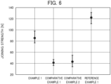
- FIG. 6 is a distribution chart of the joining strengths of the joining structure samples of Example 1, Comparative Examples 1 and 2, and Reference Example 1.
- the results show that the joining structure sample of Example 1, in which the second resin has, as physical properties, a higher foaming ratio and a higher tendency to be hot-molten than the first resin, is superior in joining strength to the joining structure sample of Comparative Example 1, in which the first resin has, as a physical property, a higher foaming ratio than the second resin, and to the joining structure sample of Comparative Example 2, in which the first resin and the second resin are the same foamed resin.
- FIG. 7A is an optical micrograph of the vertical cross section of the joining structure sample of Example 1 including the recessed joining portion.
- FIG. 7B is an optical micrograph of the joining surface of the first member after separation of the first and second members constituting the joining structure sample of Example 1 from each other at the joining interface position.
- FIG. 8A is an optical micrograph of the vertical cross section of the joining structure sample of Comparative Example 2 including the recessed joining portion.
- FIG. 8B is an optical micrograph of the joining surface of the first member after separation of the first and second members constituting the joining structure sample of Comparative Example 2 from each other at the joining interface position.
- a comparison between FIG. 7B and FIG. 8B shows that the joining structure sample of Example 1, in which the second resin has, as a physical property, a higher foaming ratio than the first resin, has a larger hot-molten portion than the joining structure sample of Comparative Example 2, in which the first and second resins are the same foamed resin.
Landscapes
- Engineering & Computer Science (AREA)
- Mechanical Engineering (AREA)
- Physics & Mathematics (AREA)
- Thermal Sciences (AREA)
- Spectroscopy & Molecular Physics (AREA)
- Architecture (AREA)
- Civil Engineering (AREA)
- Structural Engineering (AREA)
- Health & Medical Sciences (AREA)
- Toxicology (AREA)
- Lining Or Joining Of Plastics Or The Like (AREA)
Applications Claiming Priority (2)
| Application Number | Priority Date | Filing Date | Title |
|---|---|---|---|
| JP2020055160 | 2020-03-25 | ||
| PCT/JP2021/012555 WO2021193828A1 (ja) | 2020-03-25 | 2021-03-25 | 接合構造、接合方法、ワイヤーハーネス用外装体およびワイヤーハーネス |
Publications (3)
| Publication Number | Publication Date |
|---|---|
| EP4105014A1 EP4105014A1 (en) | 2022-12-21 |
| EP4105014A4 EP4105014A4 (en) | 2023-07-26 |
| EP4105014B1 true EP4105014B1 (en) | 2024-12-25 |
Family
ID=77891874
Family Applications (1)
| Application Number | Title | Priority Date | Filing Date |
|---|---|---|---|
| EP21776247.5A Active EP4105014B1 (en) | 2020-03-25 | 2021-03-25 | Joining structure, joining method, exterior body for wire harness, and wire harness |
Country Status (5)
| Country | Link |
|---|---|
| US (1) | US12191643B2 (https=) |
| EP (1) | EP4105014B1 (https=) |
| JP (1) | JP7717679B2 (https=) |
| CN (1) | CN115243879A (https=) |
| WO (1) | WO2021193828A1 (https=) |
Families Citing this family (2)
| Publication number | Priority date | Publication date | Assignee | Title |
|---|---|---|---|---|
| JP2023182039A (ja) * | 2022-06-14 | 2023-12-26 | 古河電気工業株式会社 | 接合構造、接合方法、電線用外装体および外装体付きワイヤハーネス |
| JPWO2024180868A1 (https=) * | 2023-02-28 | 2024-09-06 |
Citations (3)
| Publication number | Priority date | Publication date | Assignee | Title |
|---|---|---|---|---|
| US3563822A (en) * | 1968-07-03 | 1971-02-16 | Branson Instr | Method for welding thermoplastic parts by sonic energy |
| JPS62227725A (ja) * | 1986-03-31 | 1987-10-06 | Tachi S Co Ltd | 柔軟弾性発泡体の超音波溶着方法 |
| WO2020012988A1 (ja) * | 2018-07-13 | 2020-01-16 | 株式会社カネカ | ワイヤーハーネスプロテクタ |
Family Cites Families (9)
| Publication number | Priority date | Publication date | Assignee | Title |
|---|---|---|---|---|
| JPS61270138A (ja) * | 1985-05-24 | 1986-11-29 | Toyota Motor Corp | 合成樹脂材料の接合方法 |
| JPH06210753A (ja) * | 1993-01-13 | 1994-08-02 | Toyoda Gosei Co Ltd | 樹脂積層体の製造方法 |
| JPH10216962A (ja) * | 1997-01-31 | 1998-08-18 | Trinity Ind Corp | 超音波溶着装置及び超音波溶着方法 |
| JP3068533U (ja) | 1999-10-27 | 2000-05-12 | 三ツ星ベルト株式会社 | 樹脂部品の固定構造 |
| WO2004067217A2 (en) * | 2003-01-30 | 2004-08-12 | Tac-Fast Systems Sa | Ultrasonic welding of resilient layers to plates |
| EP2402392B1 (en) | 2004-11-25 | 2013-09-18 | Mitsui Chemicals, Inc. | Propylene resin composition and use thereof |
| JP2006272709A (ja) * | 2005-03-29 | 2006-10-12 | Shigeru Co Ltd | 車両用天井材及びその製造方法。 |
| JP6310608B1 (ja) * | 2017-06-30 | 2018-04-11 | 古河電気工業株式会社 | 電線用外装体及び外装体付きワイヤーハーネス |
| JP7328318B2 (ja) * | 2019-02-22 | 2023-08-16 | 古河電気工業株式会社 | 電線用外装体及び外装体付きワイヤーハーネス |
-
2021
- 2021-03-25 JP JP2022510667A patent/JP7717679B2/ja active Active
- 2021-03-25 WO PCT/JP2021/012555 patent/WO2021193828A1/ja not_active Ceased
- 2021-03-25 EP EP21776247.5A patent/EP4105014B1/en active Active
- 2021-03-25 CN CN202180020163.4A patent/CN115243879A/zh active Pending
-
2022
- 2022-09-13 US US17/931,643 patent/US12191643B2/en active Active
Patent Citations (3)
| Publication number | Priority date | Publication date | Assignee | Title |
|---|---|---|---|---|
| US3563822A (en) * | 1968-07-03 | 1971-02-16 | Branson Instr | Method for welding thermoplastic parts by sonic energy |
| JPS62227725A (ja) * | 1986-03-31 | 1987-10-06 | Tachi S Co Ltd | 柔軟弾性発泡体の超音波溶着方法 |
| WO2020012988A1 (ja) * | 2018-07-13 | 2020-01-16 | 株式会社カネカ | ワイヤーハーネスプロテクタ |
Also Published As
| Publication number | Publication date |
|---|---|
| US12191643B2 (en) | 2025-01-07 |
| JPWO2021193828A1 (https=) | 2021-09-30 |
| EP4105014A1 (en) | 2022-12-21 |
| US20230006430A1 (en) | 2023-01-05 |
| EP4105014A4 (en) | 2023-07-26 |
| WO2021193828A1 (ja) | 2021-09-30 |
| CN115243879A (zh) | 2022-10-25 |
| JP7717679B2 (ja) | 2025-08-04 |
Similar Documents
| Publication | Publication Date | Title |
|---|---|---|
| US12191643B2 (en) | Joining structure, joining method, exterior body for wire harness, and wire harness | |
| US12134236B2 (en) | Bonding objects together | |
| JP6798471B2 (ja) | ワイヤーハーネスおよびワイヤーハーネスの製造方法 | |
| US11787353B2 (en) | Wire harness fixing structure and wire harness | |
| JP6162170B2 (ja) | 被覆材 | |
| MXPA04005379A (es) | Metodo de preparar un articulo. | |
| JP2005504640A (ja) | 複合構造部品およびその製造方法 | |
| US9349509B2 (en) | Wire harness and manufacturing method for wire harness | |
| US20240355503A1 (en) | Wiring member | |
| JP2013005623A (ja) | ワイヤーハーネス用保護材料及びワイヤーハーネス | |
| JP2019179630A (ja) | ワイヤーハーネス及びワイヤーハーネスの製造方法 | |
| JP5431783B2 (ja) | 自動車用フロア材 | |
| JP2013023171A (ja) | 車両用内装部品およびその製造方法 | |
| JP7328318B2 (ja) | 電線用外装体及び外装体付きワイヤーハーネス | |
| JP5243976B2 (ja) | 自動車内装材固定用係止部材 | |
| JP2014151558A (ja) | 繊維強化熱可塑性樹脂一体化構造体の製造方法 | |
| JP2017152401A (ja) | 被覆材 | |
| JPS6215333B2 (https=) | ||
| EP4239820B1 (en) | Joining structure, method of producing same, and wire exterior cover | |
| JP4522242B2 (ja) | 被覆材料を構造物に固定するための取り付け金具及び取り付け方法 | |
| JP2006326997A (ja) | 超音波融着部位にシボを設けた一対の成形品 | |
| JP2007021965A (ja) | 貫通部に突起を嵌挿し融着した一対の成形品 | |
| JPS6038122A (ja) | 発泡体被覆パイプの製造方法 | |
| JP2002067689A (ja) | 車両用のサンバイザ及びその製造方法 | |
| JP2017136174A (ja) | ファスナー付き樹脂シート |
Legal Events
| Date | Code | Title | Description |
|---|---|---|---|
| STAA | Information on the status of an ep patent application or granted ep patent |
Free format text: STATUS: THE INTERNATIONAL PUBLICATION HAS BEEN MADE |
|
| PUAI | Public reference made under article 153(3) epc to a published international application that has entered the european phase |
Free format text: ORIGINAL CODE: 0009012 |
|
| STAA | Information on the status of an ep patent application or granted ep patent |
Free format text: STATUS: REQUEST FOR EXAMINATION WAS MADE |
|
| 17P | Request for examination filed |
Effective date: 20220915 |
|
| AK | Designated contracting states |
Kind code of ref document: A1 Designated state(s): AL AT BE BG CH CY CZ DE DK EE ES FI FR GB GR HR HU IE IS IT LI LT LU LV MC MK MT NL NO PL PT RO RS SE SI SK SM TR |
|
| REG | Reference to a national code |
Ref legal event code: R079 Ref country code: DE Ref document number: 602021023951 Country of ref document: DE Free format text: PREVIOUS MAIN CLASS: B32B0005240000 Ipc: B32B0027060000 |
|
| DAV | Request for validation of the european patent (deleted) | ||
| DAX | Request for extension of the european patent (deleted) | ||
| A4 | Supplementary search report drawn up and despatched |
Effective date: 20230623 |
|
| RIC1 | Information provided on ipc code assigned before grant |
Ipc: B29C 65/08 20060101ALI20230619BHEP Ipc: B29C 65/56 20060101ALI20230619BHEP Ipc: B29C 65/18 20060101ALI20230619BHEP Ipc: B32B 27/32 20060101ALI20230619BHEP Ipc: B32B 5/18 20060101ALI20230619BHEP Ipc: B32B 3/30 20060101ALI20230619BHEP Ipc: B32B 3/26 20060101ALI20230619BHEP Ipc: B32B 27/06 20060101AFI20230619BHEP |
|
| STAA | Information on the status of an ep patent application or granted ep patent |
Free format text: STATUS: EXAMINATION IS IN PROGRESS |
|
| 17Q | First examination report despatched |
Effective date: 20240206 |
|
| GRAP | Despatch of communication of intention to grant a patent |
Free format text: ORIGINAL CODE: EPIDOSNIGR1 |
|
| STAA | Information on the status of an ep patent application or granted ep patent |
Free format text: STATUS: GRANT OF PATENT IS INTENDED |
|
| INTG | Intention to grant announced |
Effective date: 20240718 |
|
| P01 | Opt-out of the competence of the unified patent court (upc) registered |
Free format text: CASE NUMBER: APP_49675/2024 Effective date: 20240902 |
|
| GRAS | Grant fee paid |
Free format text: ORIGINAL CODE: EPIDOSNIGR3 |
|
| GRAA | (expected) grant |
Free format text: ORIGINAL CODE: 0009210 |
|
| STAA | Information on the status of an ep patent application or granted ep patent |
Free format text: STATUS: THE PATENT HAS BEEN GRANTED |
|
| AK | Designated contracting states |
Kind code of ref document: B1 Designated state(s): AL AT BE BG CH CY CZ DE DK EE ES FI FR GB GR HR HU IE IS IT LI LT LU LV MC MK MT NL NO PL PT RO RS SE SI SK SM TR |
|
| RAP3 | Party data changed (applicant data changed or rights of an application transferred) |
Owner name: FURUKAWA AUTOMOTIVE SYSTEMS INC. Owner name: FURUKAWA ELECTRIC CO., LTD. |
|
| REG | Reference to a national code |
Ref country code: GB Ref legal event code: FG4D |
|
| REG | Reference to a national code |
Ref country code: CH Ref legal event code: EP |
|
| REG | Reference to a national code |
Ref country code: DE Ref legal event code: R096 Ref document number: 602021023951 Country of ref document: DE |
|
| REG | Reference to a national code |
Ref country code: IE Ref legal event code: FG4D |
|
| REG | Reference to a national code |
Ref country code: LT Ref legal event code: MG9D |
|
| PG25 | Lapsed in a contracting state [announced via postgrant information from national office to epo] |
Ref country code: HR Free format text: LAPSE BECAUSE OF FAILURE TO SUBMIT A TRANSLATION OF THE DESCRIPTION OR TO PAY THE FEE WITHIN THE PRESCRIBED TIME-LIMIT Effective date: 20241225 |
|
| PG25 | Lapsed in a contracting state [announced via postgrant information from national office to epo] |
Ref country code: FI Free format text: LAPSE BECAUSE OF FAILURE TO SUBMIT A TRANSLATION OF THE DESCRIPTION OR TO PAY THE FEE WITHIN THE PRESCRIBED TIME-LIMIT Effective date: 20241225 |
|
| PG25 | Lapsed in a contracting state [announced via postgrant information from national office to epo] |
Ref country code: BG Free format text: LAPSE BECAUSE OF FAILURE TO SUBMIT A TRANSLATION OF THE DESCRIPTION OR TO PAY THE FEE WITHIN THE PRESCRIBED TIME-LIMIT Effective date: 20241225 |
|
| PG25 | Lapsed in a contracting state [announced via postgrant information from national office to epo] |
Ref country code: NO Free format text: LAPSE BECAUSE OF FAILURE TO SUBMIT A TRANSLATION OF THE DESCRIPTION OR TO PAY THE FEE WITHIN THE PRESCRIBED TIME-LIMIT Effective date: 20250325 |
|
| PG25 | Lapsed in a contracting state [announced via postgrant information from national office to epo] |
Ref country code: LV Free format text: LAPSE BECAUSE OF FAILURE TO SUBMIT A TRANSLATION OF THE DESCRIPTION OR TO PAY THE FEE WITHIN THE PRESCRIBED TIME-LIMIT Effective date: 20241225 Ref country code: GR Free format text: LAPSE BECAUSE OF FAILURE TO SUBMIT A TRANSLATION OF THE DESCRIPTION OR TO PAY THE FEE WITHIN THE PRESCRIBED TIME-LIMIT Effective date: 20250326 |
|
| PGFP | Annual fee paid to national office [announced via postgrant information from national office to epo] |
Ref country code: AT Payment date: 20250417 Year of fee payment: 5 |
|
| PG25 | Lapsed in a contracting state [announced via postgrant information from national office to epo] |
Ref country code: RS Free format text: LAPSE BECAUSE OF FAILURE TO SUBMIT A TRANSLATION OF THE DESCRIPTION OR TO PAY THE FEE WITHIN THE PRESCRIBED TIME-LIMIT Effective date: 20250325 |
|
| REG | Reference to a national code |
Ref country code: NL Ref legal event code: MP Effective date: 20241225 |
|
| PG25 | Lapsed in a contracting state [announced via postgrant information from national office to epo] |
Ref country code: NL Free format text: LAPSE BECAUSE OF FAILURE TO SUBMIT A TRANSLATION OF THE DESCRIPTION OR TO PAY THE FEE WITHIN THE PRESCRIBED TIME-LIMIT Effective date: 20241225 |
|
| REG | Reference to a national code |
Ref country code: AT Ref legal event code: MK05 Ref document number: 1753841 Country of ref document: AT Kind code of ref document: T Effective date: 20241225 |
|
| PG25 | Lapsed in a contracting state [announced via postgrant information from national office to epo] |
Ref country code: SM Free format text: LAPSE BECAUSE OF FAILURE TO SUBMIT A TRANSLATION OF THE DESCRIPTION OR TO PAY THE FEE WITHIN THE PRESCRIBED TIME-LIMIT Effective date: 20241225 |
|
| PG25 | Lapsed in a contracting state [announced via postgrant information from national office to epo] |
Ref country code: PL Free format text: LAPSE BECAUSE OF FAILURE TO SUBMIT A TRANSLATION OF THE DESCRIPTION OR TO PAY THE FEE WITHIN THE PRESCRIBED TIME-LIMIT Effective date: 20241225 |
|
| PG25 | Lapsed in a contracting state [announced via postgrant information from national office to epo] |
Ref country code: ES Free format text: LAPSE BECAUSE OF FAILURE TO SUBMIT A TRANSLATION OF THE DESCRIPTION OR TO PAY THE FEE WITHIN THE PRESCRIBED TIME-LIMIT Effective date: 20241225 |
|
| PG25 | Lapsed in a contracting state [announced via postgrant information from national office to epo] |
Ref country code: IS Free format text: LAPSE BECAUSE OF FAILURE TO SUBMIT A TRANSLATION OF THE DESCRIPTION OR TO PAY THE FEE WITHIN THE PRESCRIBED TIME-LIMIT Effective date: 20250425 |
|
| PG25 | Lapsed in a contracting state [announced via postgrant information from national office to epo] |
Ref country code: PT Free format text: LAPSE BECAUSE OF FAILURE TO SUBMIT A TRANSLATION OF THE DESCRIPTION OR TO PAY THE FEE WITHIN THE PRESCRIBED TIME-LIMIT Effective date: 20250428 |
|
| PG25 | Lapsed in a contracting state [announced via postgrant information from national office to epo] |
Ref country code: EE Free format text: LAPSE BECAUSE OF FAILURE TO SUBMIT A TRANSLATION OF THE DESCRIPTION OR TO PAY THE FEE WITHIN THE PRESCRIBED TIME-LIMIT Effective date: 20241225 |
|
| PG25 | Lapsed in a contracting state [announced via postgrant information from national office to epo] |
Ref country code: RO Free format text: LAPSE BECAUSE OF FAILURE TO SUBMIT A TRANSLATION OF THE DESCRIPTION OR TO PAY THE FEE WITHIN THE PRESCRIBED TIME-LIMIT Effective date: 20241225 Ref country code: AT Free format text: LAPSE BECAUSE OF FAILURE TO SUBMIT A TRANSLATION OF THE DESCRIPTION OR TO PAY THE FEE WITHIN THE PRESCRIBED TIME-LIMIT Effective date: 20241225 |
|
| PG25 | Lapsed in a contracting state [announced via postgrant information from national office to epo] |
Ref country code: SK Free format text: LAPSE BECAUSE OF FAILURE TO SUBMIT A TRANSLATION OF THE DESCRIPTION OR TO PAY THE FEE WITHIN THE PRESCRIBED TIME-LIMIT Effective date: 20241225 |
|
| PG25 | Lapsed in a contracting state [announced via postgrant information from national office to epo] |
Ref country code: CZ Free format text: LAPSE BECAUSE OF FAILURE TO SUBMIT A TRANSLATION OF THE DESCRIPTION OR TO PAY THE FEE WITHIN THE PRESCRIBED TIME-LIMIT Effective date: 20241225 |
|
| PG25 | Lapsed in a contracting state [announced via postgrant information from national office to epo] |
Ref country code: IT Free format text: LAPSE BECAUSE OF FAILURE TO SUBMIT A TRANSLATION OF THE DESCRIPTION OR TO PAY THE FEE WITHIN THE PRESCRIBED TIME-LIMIT Effective date: 20241225 |
|
| PG25 | Lapsed in a contracting state [announced via postgrant information from national office to epo] |
Ref country code: SE Free format text: LAPSE BECAUSE OF FAILURE TO SUBMIT A TRANSLATION OF THE DESCRIPTION OR TO PAY THE FEE WITHIN THE PRESCRIBED TIME-LIMIT Effective date: 20241225 |
|
| REG | Reference to a national code |
Ref country code: DE Ref legal event code: R097 Ref document number: 602021023951 Country of ref document: DE |
|
| PG25 | Lapsed in a contracting state [announced via postgrant information from national office to epo] |
Ref country code: DK Free format text: LAPSE BECAUSE OF FAILURE TO SUBMIT A TRANSLATION OF THE DESCRIPTION OR TO PAY THE FEE WITHIN THE PRESCRIBED TIME-LIMIT Effective date: 20241225 |
|
| PG25 | Lapsed in a contracting state [announced via postgrant information from national office to epo] |
Ref country code: MC Free format text: LAPSE BECAUSE OF FAILURE TO SUBMIT A TRANSLATION OF THE DESCRIPTION OR TO PAY THE FEE WITHIN THE PRESCRIBED TIME-LIMIT Effective date: 20241225 |
|
| REG | Reference to a national code |
Ref country code: CH Ref legal event code: H13 Free format text: ST27 STATUS EVENT CODE: U-0-0-H10-H13 (AS PROVIDED BY THE NATIONAL OFFICE) Effective date: 20251023 |
|
| PLBE | No opposition filed within time limit |
Free format text: ORIGINAL CODE: 0009261 |
|
| STAA | Information on the status of an ep patent application or granted ep patent |
Free format text: STATUS: NO OPPOSITION FILED WITHIN TIME LIMIT |
|
| PG25 | Lapsed in a contracting state [announced via postgrant information from national office to epo] |
Ref country code: LU Free format text: LAPSE BECAUSE OF NON-PAYMENT OF DUE FEES Effective date: 20250325 |
|
| GBPC | Gb: european patent ceased through non-payment of renewal fee |
Effective date: 20250325 |
|
| 26N | No opposition filed |
Effective date: 20250926 |
|
| REG | Reference to a national code |
Ref country code: BE Ref legal event code: MM Effective date: 20250331 |
|
| PG25 | Lapsed in a contracting state [announced via postgrant information from national office to epo] |
Ref country code: GB Free format text: LAPSE BECAUSE OF NON-PAYMENT OF DUE FEES Effective date: 20250325 |
|
| PG25 | Lapsed in a contracting state [announced via postgrant information from national office to epo] |
Ref country code: FR Free format text: LAPSE BECAUSE OF NON-PAYMENT OF DUE FEES Effective date: 20250331 |
|
| PG25 | Lapsed in a contracting state [announced via postgrant information from national office to epo] |
Ref country code: BE Free format text: LAPSE BECAUSE OF NON-PAYMENT OF DUE FEES Effective date: 20250331 |
|
| PG25 | Lapsed in a contracting state [announced via postgrant information from national office to epo] |
Ref country code: CH Free format text: LAPSE BECAUSE OF NON-PAYMENT OF DUE FEES Effective date: 20250331 |
|
| PG25 | Lapsed in a contracting state [announced via postgrant information from national office to epo] |
Ref country code: IE Free format text: LAPSE BECAUSE OF NON-PAYMENT OF DUE FEES Effective date: 20250325 |
|
| PGFP | Annual fee paid to national office [announced via postgrant information from national office to epo] |
Ref country code: DE Payment date: 20260128 Year of fee payment: 6 |