EP4097798B1 - Schutzerdungskontakt und leiteranschlussklemme - Google Patents
Schutzerdungskontakt und leiteranschlussklemme Download PDFInfo
- Publication number
- EP4097798B1 EP4097798B1 EP20812277.0A EP20812277A EP4097798B1 EP 4097798 B1 EP4097798 B1 EP 4097798B1 EP 20812277 A EP20812277 A EP 20812277A EP 4097798 B1 EP4097798 B1 EP 4097798B1
- Authority
- EP
- European Patent Office
- Prior art keywords
- protective earthing
- earthing contact
- contact
- protective
- conductor
- Prior art date
- Legal status (The legal status is an assumption and is not a legal conclusion. Google has not performed a legal analysis and makes no representation as to the accuracy of the status listed.)
- Active
Links
Images


Classifications
-
- H—ELECTRICITY
- H01—ELECTRIC ELEMENTS
- H01R—ELECTRICALLY-CONDUCTIVE CONNECTIONS; STRUCTURAL ASSOCIATIONS OF A PLURALITY OF MUTUALLY-INSULATED ELECTRICAL CONNECTING ELEMENTS; COUPLING DEVICES; CURRENT COLLECTORS
- H01R13/00—Details of coupling devices of the kinds covered by groups H01R12/70 or H01R24/00 - H01R33/00
- H01R13/648—Protective earth or shield arrangements on coupling devices, e.g. anti-static shielding
- H01R13/652—Protective earth or shield arrangements on coupling devices, e.g. anti-static shielding with earth pin, blade or socket
-
- H—ELECTRICITY
- H01—ELECTRIC ELEMENTS
- H01R—ELECTRICALLY-CONDUCTIVE CONNECTIONS; STRUCTURAL ASSOCIATIONS OF A PLURALITY OF MUTUALLY-INSULATED ELECTRICAL CONNECTING ELEMENTS; COUPLING DEVICES; CURRENT COLLECTORS
- H01R13/00—Details of coupling devices of the kinds covered by groups H01R12/70 or H01R24/00 - H01R33/00
- H01R13/02—Contact members
- H01R13/15—Pins, blades or sockets having separate spring member for producing or increasing contact pressure
- H01R13/17—Pins, blades or sockets having separate spring member for producing or increasing contact pressure with spring member on the pin
-
- H—ELECTRICITY
- H01—ELECTRIC ELEMENTS
- H01R—ELECTRICALLY-CONDUCTIVE CONNECTIONS; STRUCTURAL ASSOCIATIONS OF A PLURALITY OF MUTUALLY-INSULATED ELECTRICAL CONNECTING ELEMENTS; COUPLING DEVICES; CURRENT COLLECTORS
- H01R4/00—Electrically-conductive connections between two or more conductive members in direct contact, i.e. touching one another; Means for effecting or maintaining such contact; Electrically-conductive connections having two or more spaced connecting locations for conductors and using contact members penetrating insulation
- H01R4/28—Clamped connections, spring connections
- H01R4/48—Clamped connections, spring connections utilising a spring, clip, or other resilient member
- H01R4/489—Clamped connections, spring connections utilising a spring, clip, or other resilient member spring force increased by screw, cam, wedge, or other fastening means
-
- H—ELECTRICITY
- H01—ELECTRIC ELEMENTS
- H01R—ELECTRICALLY-CONDUCTIVE CONNECTIONS; STRUCTURAL ASSOCIATIONS OF A PLURALITY OF MUTUALLY-INSULATED ELECTRICAL CONNECTING ELEMENTS; COUPLING DEVICES; CURRENT COLLECTORS
- H01R11/00—Individual connecting elements providing two or more spaced connecting locations for conductive members which are, or may be, thereby interconnected, e.g. end pieces for wires or cables supported by the wire or cable and having means for facilitating electrical connection to some other wire, terminal, or conductive member, blocks of binding posts
- H01R11/03—Individual connecting elements providing two or more spaced connecting locations for conductive members which are, or may be, thereby interconnected, e.g. end pieces for wires or cables supported by the wire or cable and having means for facilitating electrical connection to some other wire, terminal, or conductive member, blocks of binding posts characterised by the relationship between the connecting locations
- H01R11/05—Individual connecting elements providing two or more spaced connecting locations for conductive members which are, or may be, thereby interconnected, e.g. end pieces for wires or cables supported by the wire or cable and having means for facilitating electrical connection to some other wire, terminal, or conductive member, blocks of binding posts characterised by the relationship between the connecting locations the connecting locations having different types of direct connections
-
- H—ELECTRICITY
- H01—ELECTRIC ELEMENTS
- H01R—ELECTRICALLY-CONDUCTIVE CONNECTIONS; STRUCTURAL ASSOCIATIONS OF A PLURALITY OF MUTUALLY-INSULATED ELECTRICAL CONNECTING ELEMENTS; COUPLING DEVICES; CURRENT COLLECTORS
- H01R13/00—Details of coupling devices of the kinds covered by groups H01R12/70 or H01R24/00 - H01R33/00
- H01R13/02—Contact members
- H01R13/15—Pins, blades or sockets having separate spring member for producing or increasing contact pressure
- H01R13/187—Pins, blades or sockets having separate spring member for producing or increasing contact pressure with spring member in the socket
-
- H—ELECTRICITY
- H01—ELECTRIC ELEMENTS
- H01R—ELECTRICALLY-CONDUCTIVE CONNECTIONS; STRUCTURAL ASSOCIATIONS OF A PLURALITY OF MUTUALLY-INSULATED ELECTRICAL CONNECTING ELEMENTS; COUPLING DEVICES; CURRENT COLLECTORS
- H01R13/00—Details of coupling devices of the kinds covered by groups H01R12/70 or H01R24/00 - H01R33/00
- H01R13/648—Protective earth or shield arrangements on coupling devices, e.g. anti-static shielding
-
- H—ELECTRICITY
- H01—ELECTRIC ELEMENTS
- H01R—ELECTRICALLY-CONDUCTIVE CONNECTIONS; STRUCTURAL ASSOCIATIONS OF A PLURALITY OF MUTUALLY-INSULATED ELECTRICAL CONNECTING ELEMENTS; COUPLING DEVICES; CURRENT COLLECTORS
- H01R4/00—Electrically-conductive connections between two or more conductive members in direct contact, i.e. touching one another; Means for effecting or maintaining such contact; Electrically-conductive connections having two or more spaced connecting locations for conductors and using contact members penetrating insulation
- H01R4/28—Clamped connections, spring connections
- H01R4/48—Clamped connections, spring connections utilising a spring, clip, or other resilient member
- H01R4/4809—Clamped connections, spring connections utilising a spring, clip, or other resilient member using a leaf spring to bias the conductor toward the busbar
- H01R4/48185—Clamped connections, spring connections utilising a spring, clip, or other resilient member using a leaf spring to bias the conductor toward the busbar adapted for axial insertion of a wire end
- H01R4/4819—Clamped connections, spring connections utilising a spring, clip, or other resilient member using a leaf spring to bias the conductor toward the busbar adapted for axial insertion of a wire end the spring shape allowing insertion of the conductor end when the spring is unbiased
- H01R4/4821—Single-blade spring
-
- H—ELECTRICITY
- H01—ELECTRIC ELEMENTS
- H01R—ELECTRICALLY-CONDUCTIVE CONNECTIONS; STRUCTURAL ASSOCIATIONS OF A PLURALITY OF MUTUALLY-INSULATED ELECTRICAL CONNECTING ELEMENTS; COUPLING DEVICES; CURRENT COLLECTORS
- H01R4/00—Electrically-conductive connections between two or more conductive members in direct contact, i.e. touching one another; Means for effecting or maintaining such contact; Electrically-conductive connections having two or more spaced connecting locations for conductors and using contact members penetrating insulation
- H01R4/28—Clamped connections, spring connections
- H01R4/48—Clamped connections, spring connections utilising a spring, clip, or other resilient member
- H01R4/4809—Clamped connections, spring connections utilising a spring, clip, or other resilient member using a leaf spring to bias the conductor toward the busbar
- H01R4/4828—Spring-activating arrangements mounted on or integrally formed with the spring housing
- H01R4/483—Pivoting arrangements, e.g. lever pushing on the spring
-
- H—ELECTRICITY
- H01—ELECTRIC ELEMENTS
- H01R—ELECTRICALLY-CONDUCTIVE CONNECTIONS; STRUCTURAL ASSOCIATIONS OF A PLURALITY OF MUTUALLY-INSULATED ELECTRICAL CONNECTING ELEMENTS; COUPLING DEVICES; CURRENT COLLECTORS
- H01R4/00—Electrically-conductive connections between two or more conductive members in direct contact, i.e. touching one another; Means for effecting or maintaining such contact; Electrically-conductive connections having two or more spaced connecting locations for conductors and using contact members penetrating insulation
- H01R4/28—Clamped connections, spring connections
- H01R4/48—Clamped connections, spring connections utilising a spring, clip, or other resilient member
- H01R4/4809—Clamped connections, spring connections utilising a spring, clip, or other resilient member using a leaf spring to bias the conductor toward the busbar
- H01R4/484—Spring housing details
-
- H—ELECTRICITY
- H01—ELECTRIC ELEMENTS
- H01R—ELECTRICALLY-CONDUCTIVE CONNECTIONS; STRUCTURAL ASSOCIATIONS OF A PLURALITY OF MUTUALLY-INSULATED ELECTRICAL CONNECTING ELEMENTS; COUPLING DEVICES; CURRENT COLLECTORS
- H01R4/00—Electrically-conductive connections between two or more conductive members in direct contact, i.e. touching one another; Means for effecting or maintaining such contact; Electrically-conductive connections having two or more spaced connecting locations for conductors and using contact members penetrating insulation
- H01R4/28—Clamped connections, spring connections
- H01R4/48—Clamped connections, spring connections utilising a spring, clip, or other resilient member
- H01R4/4809—Clamped connections, spring connections utilising a spring, clip, or other resilient member using a leaf spring to bias the conductor toward the busbar
- H01R4/4846—Busbar details
- H01R4/4848—Busbar integrally formed with the spring
-
- H—ELECTRICITY
- H01—ELECTRIC ELEMENTS
- H01R—ELECTRICALLY-CONDUCTIVE CONNECTIONS; STRUCTURAL ASSOCIATIONS OF A PLURALITY OF MUTUALLY-INSULATED ELECTRICAL CONNECTING ELEMENTS; COUPLING DEVICES; CURRENT COLLECTORS
- H01R4/00—Electrically-conductive connections between two or more conductive members in direct contact, i.e. touching one another; Means for effecting or maintaining such contact; Electrically-conductive connections having two or more spaced connecting locations for conductors and using contact members penetrating insulation
- H01R4/28—Clamped connections, spring connections
- H01R4/48—Clamped connections, spring connections utilising a spring, clip, or other resilient member
- H01R4/4809—Clamped connections, spring connections utilising a spring, clip, or other resilient member using a leaf spring to bias the conductor toward the busbar
- H01R4/4846—Busbar details
- H01R4/485—Single busbar common to multiple springs
-
- H—ELECTRICITY
- H01—ELECTRIC ELEMENTS
- H01R—ELECTRICALLY-CONDUCTIVE CONNECTIONS; STRUCTURAL ASSOCIATIONS OF A PLURALITY OF MUTUALLY-INSULATED ELECTRICAL CONNECTING ELEMENTS; COUPLING DEVICES; CURRENT COLLECTORS
- H01R4/00—Electrically-conductive connections between two or more conductive members in direct contact, i.e. touching one another; Means for effecting or maintaining such contact; Electrically-conductive connections having two or more spaced connecting locations for conductors and using contact members penetrating insulation
- H01R4/58—Electrically-conductive connections between two or more conductive members in direct contact, i.e. touching one another; Means for effecting or maintaining such contact; Electrically-conductive connections having two or more spaced connecting locations for conductors and using contact members penetrating insulation characterised by the form or material of the contacting members
- H01R4/66—Connections with the terrestrial mass, e.g. earth plate, earth pin
-
- H—ELECTRICITY
- H01—ELECTRIC ELEMENTS
- H01R—ELECTRICALLY-CONDUCTIVE CONNECTIONS; STRUCTURAL ASSOCIATIONS OF A PLURALITY OF MUTUALLY-INSULATED ELECTRICAL CONNECTING ELEMENTS; COUPLING DEVICES; CURRENT COLLECTORS
- H01R9/00—Structural associations of a plurality of mutually-insulated electrical connecting elements, e.g. terminal strips or terminal blocks; Terminals or binding posts mounted upon a base or in a case; Bases therefor
- H01R9/22—Bases, e.g. strip, block, panel
- H01R9/24—Terminal blocks
- H01R9/2483—Terminal blocks specially adapted for ground connection
Definitions
- the invention relates to a protective earthing contact for the electrically conductive connection of a protective earthing line to an electrically conductive carrier element, wherein the protective earthing contact has a base section, wherein two side elements protrude from the base section and each side element has an upper region, wherein the upper regions form a latching region for clamping the protective earthing contact to the carrier element and wherein at least one side element has a protective earthing contact element for electrically conductive contacting of the carrier element.
- the invention relates to a conductor connection terminal with a housing with a busbar, with a spring-loaded clamp connection, wherein the busbar and the spring-loaded clamp connection form a clamping point for an electrical conductor to be clamped, and with an above-mentioned protective earthing contact for the electrically conductive connection of a protective earthing line to the busbar, wherein the protective earthing contact has a base section, wherein two side elements protrude from the base section and each side element has an upper region, wherein the upper regions form a latching region for clamping the protective earthing contact to the busbar and wherein at least one side element has a protective earthing contact element for the electrically conductive contacting of the carrier element.
- a protective earthing contact is a mandatory requirement for mains connection terminals. Such protective earthing contacts must be securely mounted and functional. A disadvantage that arises is the increased height of the mains connection terminal, which, particularly in the lighting industry, is limited by other components of a luminaire. A further disadvantage can arise if the same protective earthing contact is repeatedly installed, which may result in the tinned contacts being damaged. Contact surfaces can be damaged, meaning that reliable function of the protective earthing contact cannot be guaranteed during repeated installation.
- EP 0 327 703 A2 is a connection terminal for electrical devices with a protective earthing contact.
- DE 20 2018 101 445 U1 is a connection terminal for the electrical connection of an electrical consumer to the installation wiring of an object.
- each of the upper regions has a contacting region, wherein the latching region and the protective earthing contact element are arranged substantially at the same height with respect to the base section.
- expansion refers specifically to an elastic deformation of the side elements, especially the upper areas of the side elements.
- Elastic deformation occurs when a force is applied to the side elements. When the applied force is removed, the side elements return to their original shape without any deformation remaining.
- At least one of the upper regions may have a chamfer in the region of the latching region, wherein the end of the chamfer facing the contacting regions and the protective earth contact element are arranged substantially at the same height with respect to the base section.
- the chamfer makes it easier to guide the carrier element between the contact areas. Furthermore, the side elements expand continuously near the top without requiring significant force to guide the carrier element between the contact areas.
- the protective earth contact element can be designed for a force-locking connection with the carrier element.
- the force-lock connection securely connects the protective earth contact element to the support element and thus to a corresponding protective earth conductor.
- a force-lock connection can be achieved, for example, by first guiding the protective earth contact element past the contact area of the support element during assembly. Contacting the protective earth contact without expanding the protective earth contact element by guiding the support element between the contact areas is therefore not possible. The protective earth contact element thus no longer returns to its original starting position, but instead makes force-lock contact with the contact area of the support element.
- the protective earthing contact can have a retaining element for positively connecting the protective earthing contact to the support element in the assembled state. It is also advantageous if the retaining element is arranged on the upper region of the side element. The overall height between the locking region and the retaining element can be smaller than the height between the locking region and the base section.
- the height between the locking area and the retaining element is a maximum of 90%, but at least a maximum of 50%, smaller than the height between the locking area and the base section.
- the retaining element secures the protective earthing contact against tilting when installed.
- the retaining element can, for example, engage in a recess on the support element to form-fit the protective earthing contact with the support element.
- the protective earthing contact is secured against tilting after installation.
- the retaining element can also, for example, engage in a fork of the support element to additionally contact the support element in the area of the retaining element. It is also conceivable, however, for the retaining element to interact with other components besides the support element to secure the protective earthing contact against tilting.
- the invention relates to a protective earthing contact for the electrically conductive connection of a protective earthing line to an electrically conductive carrier element, wherein the protective earthing contact has a base section, wherein two side elements protrude from the base section and each side element has an upper region, wherein the upper regions form a latching region for clamping the protective earthing contact to the carrier element and wherein at least one Side element has a protective earth contact element for electrically conductive contact with the carrier element, wherein the protective earth contact has a holding element for positively connecting the protective earth contact in the assembled state to the carrier element.
- the installed protective earthing contact for example, in a conductor terminal, can simultaneously fulfill the additional function of a conductor guide.
- This can be achieved, for example, by means of curved upper sections, whereby an electrical conductor comes into contact with a curved upper section and can thus be guided into the correct position in the conductor terminal.
- a conductor connection terminal of the type mentioned above can be equipped with a protective earthing contact as described above.
- At least one of the side elements can have a guide contour for guiding the electrical conductor into the housing.
- the guide contour can be arranged on the upper region of the side element. It is also advantageous if the guide contour interacts with the housing and/or with a conductor stop for the electrical conductor in such a way that the protective earthing contact is stabilized.
- the protective earthing contact can have a holding element, whereby the holding element is located in the interior of the conductor connection terminal in the area of the electrical Ladders can be arranged.
- the busbar can have a recess, wherein the retaining element engages in the recess for the positive connection of the protective earthing contact to the busbar.
- the retaining element is thus positioned in the area of the terminal point for the electrical conductor.
- the holding element can be arranged at the end of the side element facing away from the base section, namely at the upper region of the side element, wherein the structural height between the locking region and the holding element is smaller than the height between the locking region and the base section.
- the conductor terminal can, for example, be designed to accommodate three or four electrical conductors. It has been shown that, particularly in the lighting industry, three or four conductor connections are particularly required for mains connection terminals. With such conductor terminals, the available space can be used to mount the protective earthing contact inside the housing.
- the protective earthing contact according to the invention has a plurality of protective earthing contact elements.
- a protective earthing contact element and a holding element are arranged on an upper area of each side element.
- the electrically conductive carrier element can be designed, for example, as a busbar of a conductor connection terminal.
- a protective earth contact element 6 is arranged on the upper region 4a of the side element 3a for electrically conductive contact of the protective earth line with the carrier element.
- the locking area 5 and the protective earth contact element 6 are arranged essentially at the same height H with respect to the base section 2 and are also spatially separated from one another.
- the side elements 3a, 3b widen in the area of the upper areas 4a, 4b so that the carrier element can be held between the contact areas 5a, 5b.
- the protective earth contact element 6 also widens by the same amount. Widening can be achieved, for example, by making the side elements 3a, 3b resilient.
- the carrier element When the carrier element reaches its final position between the contact areas 5a, 5b, the side elements 3a, 3b in the area of the upper areas 4a, 4b, and thus also the protective earth contact element 6, spring back to their original position, thus holding the carrier element between the contact areas 5a, 5b.
- This makes it possible for a tinned protective earth contact element 6, for example, to be guided past the contact surface on the carrier element without contact, thus reducing wear on the tinned protective earth contact element 6.
- the contact surface of the carrier element is the surface with which the protective earth contact element 6 is intended to come into contact.
- a chamfer 7a, 7b is arranged on each of the upper regions 4a, 4b in the region of the locking region 5.
- the end of the chamfers 7a, 7b facing the contacting regions 5a, 5b is arranged at the same height as the protective earth contact element 6 with respect to the base section 2.
- the chamfers 7a, 7b make it easier to guide the carrier element to the locking region 5.
- the side elements 3a, 3b continuously widen in the region of the upper regions 4a, 4b without the need for a correspondingly large force to guide the carrier element between the contacting regions 5a, 5b.
- the protective earth contact element 6 should be exactly level with the locking area 5 and the ends of the bevels 7a, 7b. However, a deviation from this is possible without limiting the function of the protective earth contact according to the invention. Deviations of 15% are permissible. Conceivable with respect to the height H of the locking area 5 and to the height H of the protective earthing contact element 6 to the base section 2.
- a holding element 8a is arranged on the upper region 4a.
- the holding element 8a is designed to positively connect the protective earthing contact 1 to the carrier element.
- the positive connection can be achieved, for example, by corresponding recesses in the carrier element. However, recesses in a housing are also conceivable.
- the positive connection secures the protective earthing contact 1 against tilting in the assembled state.
- the holding element 8a can be designed as a protective earthing contact element 6.
- the protective earthing contact 1 has a contact tongue 16, wherein the contact tongue 16 is designed to electrically connect the protective earthing contact 1 directly or indirectly to a protective earthing line.
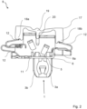
- Figure 2 shows a conductor terminal 9, in particular a mains terminal for the lighting industry.
- the conductor terminal 9 has a busbar 11 and three spring-loaded terminals 12 for connecting three electrical conductors.
- the protective earthing contact 1 is Figure 1 mounted in the conductor connection terminal 9.
- the contact area of the protective earth contact element 6 on the busbar 11 is arranged separately from the locking area 5 so that the protective earth contact element 6 can be guided contact-free through a recess in the busbar 11.
- a force-locking connection is provided between the protective earth contact element 6 and the busbar 11. This can be achieved, for example, by designing the dimensions of the recess in the busbar 11 such that the protective earth contact element 6 can be guided past the busbar 11 without contact when the side elements 3a, 3b are in the expanded state.
- the holding element 8a is arranged in the interior of the conductor connection terminal 9 in the area of the electrical conductors to be connected, whereby the busbar 11 is not arranged between the spring-loaded terminal connection 12 and the holding element 8a.
- the electrical conductors can therefore be inserted into the same space of the conductor connection terminal 9 by arranging the holding element 8a in the assembled state. This utilizes the available space of the conductor connection terminal 1 without having to dimension it larger.
- the holding element 8a engages in a recess in the busbar 11 and stabilizes the protective earthing contact 1 against tilting through a positive connection with the busbar 11 in the assembled state. This ensures safe operation.
- the Figure 2 1 also shows an actuating arrangement 17, with which, on the one hand, the upper spring-loaded terminal connection 12 of the arrangement comprising the two spring-loaded terminal connections 12 (left area) and, on the other hand, the individual spring-loaded terminal connection 12 (right area) can each be manually actuated independently of one another in order to deflect the associated clamping leg and thereby open the clamping point.
- the actuating arrangement 6 has an actuating section 18a for one spring-loaded terminal connection 12 and an actuating section 18b for the other, opposite spring-loaded terminal connection 12.
- the actuating sections 18a, 18b are connected to one another via a connecting section 19 arranged approximately centrally between the actuating sections 18a, 18b.
- a T-shaped protruding material section 20 is provided on the connecting section 19 between the actuating sections 18a, 18b, e.g., centrally or slightly off-center between the actuating sections 18a, 18b.
- the T-shaped protruding material section 20 is displaceably mounted on the busbar 11.
- the geometric design of the actuating arrangement 6 makes it possible to actuate the spring-loaded terminal connections 12 independently of one another.
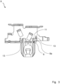
- Figure 3 shows the conductor connection terminal 9 to Figure 2 in another sectional view.
- the busbar 11 has recesses 13 through which the protective earth contact element 6 can be passed for assembly, with the protective earth contact element 6 being connected to the busbar 11 in a force-fitting manner and the holding element 8a being connected to the busbar 11 in a form-fitting manner.
- the holding element 8a can be connected to the busbar 11 in a force-fitting manner and the protective earth contact element 6 can be connected to the busbar 11 in a form-fitting manner.
- Figures 4 and 5 show a second embodiment of a protective earthing contact 1, wherein the protective earthing contact in Figure 4 in a front view and in Figure 5 shown in a rotated view.
- the protective earthing contact 1 has a base section 2, with two side elements 3a, 3b projecting from the base section in the same direction.
- the side elements 3a, 3b each have an upper region 4a, 4b.
- the protective earthing contact has two protective earthing contact elements 6, which are arranged at the same height H with respect to the base section 2 with the latching area 5, so that the protective earthing contact elements 6 are widened when the protective earthing contact 1 is installed and can thus be inserted contactlessly into a corresponding conductor connection terminal.
- the ends of the side elements 3a, 3b are designed as guide contours 14a, 14b.
- Such guide contours 14a, 14b have the advantage that, when installed, they form an electrical conductor to the corresponding terminal point without the electrical conductor touching the protective earthing contact elements 6.
- the protective earthing contact 1 has a contact tongue 16, wherein the contact tongue 16 is designed to electrically connect the protective earthing contact 1 directly or indirectly to a protective earthing line.
- Figure 6 shows a conductor terminal 9, in particular a mains terminal for the lighting industry in a sectional view.
- the conductor terminal 9 has a busbar 11 and four spring-loaded terminals 12 for connecting four electrical conductors.
- the protective earthing contact 1 is arranged according to the Figures 4 and 5 mounted in the conductor connection terminal 9.
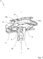
- Figure 7 shows the conductor connection terminal 9 to Figure 6 in a rotated view. It is clear that the conductor connection terminal 9 has conductor stops 15 for the electrical conductors to be connected. It is also clear that the protective earthing contact 1 utilizes the existing contours and available space of the busbar 11 of the conductor connection terminal 9, so that the conductor connection terminal does not need to be designed larger in the interior to accommodate the protective earthing contact 1.
- the guide contours 14a, 14b rest against the conductor stops 15 in such a way that the entire protective earthing contact 1 is stabilized and protected against tilting. The movement of the protective earthing contact 1 is thus limited in the direction of the conductor stops 15.
- Figure 8 shows a section of the conductor connection terminal 9 according to the Figures 6 and 7 in a top view.
- the side elements 3a, 3b with the guide contours 14a, 14b of the protective earthing contact 1 are visible. It is clear that the guide contours 14a, 14b can guide electrical conductors to the conductor stops 15 without the electrical conductors touching the protective earthing contact elements 6, since the protective earthing contact elements 6 are arranged on a side facing away from the conductor stops 15.
- the protective earthing contact 1 can therefore be designed such that the electrical conductors do not collide with the protective earthing contact elements 6 when connected.
- a design is also conceivable without guide contours 14a, 14b, for example, by having one or more protective earthing contact elements 6 protrude at a right angle from the side element 3a and/or from the side element 3b. This does not require an exact right angle of 90°. A deviation of 25° in the positive or negative direction is conceivable.
- the guide contours 14a, 14b interact with the contour of a housing 10, so that the protective earthing contact 1 is additionally stabilized.
- the protective earthing contact 1 is thus stabilized by the conductor stops 15 and the housing 10 and protected against tilting by limiting its degrees of freedom by the housing 10 and the conductor stops 15.
Landscapes
- Connections Arranged To Contact A Plurality Of Conductors (AREA)
Description
- Die Erfindung betrifft einen Schutzerdungskontakt zur elektrisch leitenden Verbindung einer Schutzerdeleitung mit einem elektrisch leitfähigen Trägerelement, wobei der Schutzerdungskontakt einen Basisabschnitt hat, wobei zwei Seitenelemente von dem Basisabschnitt abragen und jeweils ein Seitenelement einen Oberbereich hat, wobei die Oberbereiche einen Rastbereich zum Anklemmen des Schutzerdungskontaktes an das Trägerelement bilden und wobei wenigstens ein Seitenelement ein Schutzerde-Kontaktelement zur elektrisch leitenden Kontaktierung des Trägerelementes hat.
- Ferner betrifft die Erfindung eine Leiteranschlussklemme mit einem Gehäuse mit einer Stromschiene, mit einem Federkraftklemmanschluss, wobei die Stromschiene und der Federkraftklemmanschluss eine Klemmstelle für einen anzuklemmenden elektrischen Leiter bilden, und mit einem oben genannten Schutzerdungskontakt zur elektrisch leitenden Verbindung einer Schutzerdeleitung mit der Stromschiene, wobei der Schutzerdungskontakt einen Basisabschnitt hat, wobei zwei Seitenelemente von dem Basisabschnitt abragen und jeweils ein Seitenelement einen Oberbereich hat, wobei die Oberbereiche einen Rastbereich zum Anklemmen des Schutzerdungskontaktes an die Stromschiene bilden und wobei wenigstens ein Seitenelement ein Schutzerde-Kontaktelement zur elektrisch leitenden Kontaktierung des Trägerelementes hat.
- Bei Netzanschlussklemmen ist ein Schutzerdungskontakt eine zwingende Vorgabe. Derartige Schutzerdungskontakte müssen sicher montiert und funktional sein. Ein Nachteil der dadurch entsteht, ist die größere Bauhöhe der Netzanschlussklemme, die, insbesondere in der Leuchtenindustrie, durch weitere Einbauteile einer Leuchte begrenzt ist. Ein weiterer Nachteil kann entstehen, wenn durch einen wiederholten Einbau desselben Schutzerdungskontaktes, wodurch die gegebenen Falls verzinnten Kontaktierungsflächen beschädigt werden können, somit eine sichere Funktion des Schutzerdungskontaktes bei wiederholtem Einbau nicht gewährleistet werden kann.
- Aus der
DE 20 2008 017 145 U1 ist ein Massekontakt für eine Erdungsschiene bekannt. Aus derEP 0 327 703 A2 ist eine Anschluss- bzw. Verbindungsklemme für elektrische Geräte mit einem Schutzerdungskontakt bekannt. Aus derDE 20 2018 101 445 U1 ist eine Anschlussklemme für die elektrische Anbindung eines elektrischen Verbrauchers an eine Installationsverdrahtung eines Objekts bekannt. - Ausgehend hiervon ist es Aufgabe der vorliegenden Erfindung einen verbesserten Schutzerdungskontakt zu schaffen. Ferner ist es Aufgabe der vorliegenden Erfindung eine verbesserte Leiteranschlussklemme zu schaffen.
- Die Aufgabe wird mit einem Schutzerdungskontakt mit den Merkmalen des Anspruchs 1 und mit einer Leiteranschlussklemme mit den Merkmalen des Anspruchs 10 gelöst. Vorteilhafte Ausführungsformen sind in den Unteransprüchen beschrieben.
- Bei dem gattungsgemäßen Schutzerdungskontakt wird vorgeschlagen, dass jeweils einer der Oberbereiche einen Kontaktierungsbereich hat, wobei der Rastbereich und das Schutzerde-Kontaktelement im Wesentlichen auf der gleichen Höhe in Bezug auf den Basisabschnitt angeordnet sind.
- Durch die Trennung des Rastbereiches und des Schutzerde-Kontaktelements wird eine Beschädigungsgefahr des Schutzerde-Kontaktelements verringert. Bei Montage des Schutzerdungskontaktes weiten sich die Oberbereiche im Rastbereich auf, damit das Trägerelement zwischen die Kontaktierungsbereiche gelangen kann. Durch die Anordnung des Schutzerde-Kontaktelementes auf derselben Höhe wie der Rastbereich in Bezug auf den Basisabschnitt, weitet sich auch das Schutzerde-Kontaktelement um das gleiche Maß wie die Oberbereiche auf, so dass das Schutzerde-Kontaktelement an einem Kontaktbereich des Trägerelementes berührungsfrei vorbeigeführt werden kann. Ist das Trägerelement vollständig zwischen die Kontaktierungsbereiche geführt, springen die Oberbereiche in die Ausgangsposition zurück und klemmen den Schutzerdungskontakt an das Trägerelement an. Gleichzeitig springt auch das Schutzerde-Kontaktelement in seine Ausgangsposition zurück und kontaktiert den Kontaktbereich des Trägerelementes.
- Der Rastbereich ist der Bereich, in dem das Trägerelement zwischen die Kontaktierungsbereiche des Schutzerdungskontaktes geführt wird. Das Trägerelement wird dabei nach Führung in die Position zwischen den Kontaktierungsbereichen gehalten. Die Kontaktierungsbereiche schließen sich also unmittelbar dem Rastbereich an.
- Unter dem Begriff Aufweitung wird insbesondere eine elastische Verformung der Seitenelemente, insbesondere der Oberbereiche der Seitenelemente, verstanden. Eine elastische Verformung tritt unter Krafteinwirkung auf die Seitenelemente ein, wobei bei Wegfall der einwirkenden Kraft die Seitenelemente in Ihre Ursprungsform zurückkehren, ohne dass eine Deformation zurückbleibt.
- Der Oberbereich ist der Bereich eines Seitenelementes, der an dem Basisabschnitt abgewandtem Ende des Seitenelements angeordnet ist. Der Oberbereich und der Basisabschnitt sind also an den gegenüberliegenden Enden des jeweiligen Seitenelementes angeordnet.
- Im Wesentlichen auf der gleichen Höhe bedeutet insbesondere, dass das Schutzerde-Kontaktelement und der Rastbereich nicht exakt die gleiche Höhe in Bezug auf den Basisabschnitt aufweisen müssen. Eine erfindungsgemäße Verwendung ist auch bei einer Abweichen von +-15 % in Bezug auf die Höhe des Schutzerde-Kontaktelementes und auf die Höhe des Rastbereiches gegeben.
- Die Höhe ist die Länge, die in Längserstreckungsrichtung der Seitenelemente sowohl zwischen dem Basisabschnitt und dem Rastbereich als auch zwischen dem Basisabschnitt und dem Schutzerde-Kontaktelement vorliegt.
- Wenigstens einer der Oberbereiche kann eine Fase im Bereich des Rastbereiches haben, wobei das den Kontaktierungsbereichen zugewandte Ende der Fase und das Schutzerde-Kontaktelement im Wesentlichen auf der gleichen Höhe in Bezug auf den Basisabschnitt angeordnet sind.
- Durch die Fase kann das Trägerelement einfacher zwischen die Kontaktierungsbereiche geführt werden. Zudem weiten sich die Seitenelemente im Bereich der Oberbereiche kontinuierlich auf, ohne das eine große Kraft aufgewendet werden muss, um das Trägerelement zwischen die Kontaktierungsbereiche zu führen.
- Das Schutzerde-Kontaktelement kann zur kraftschlüssigen Verbindung mit dem Trägerelement ausgebildet sein.
- Die kraftschlüssige Verbindung kontaktiert das Schutzerde-Kontaktelement sicher an dem Trägerelement und damit an einer entsprechenden Schutzerdeleitung. Eine kraftschlüssige Verbindung kann zum Beispiel dadurch erreicht werden, dass das Schutzerde-Kontaktelement bei der Montage erst an dem Kontaktbereich des Trägerelementes vorbeigeführt werden muss. Eine Kontaktierung des Schutzerdungskontaktes ohne eine Aufweitung des Schutzerde-Kontaktelementes durch eine Führung des Trägerelementes zwischen die Kontaktierungsbereiche ist so nicht möglich. Das Schutzerde-Kontaktelement gelangt so nicht mehr in seine ursprüngliche Ausgangsposition zurück, sondern kontaktiert den Kontaktbereich des Trägerelementes kraftschlüssig.
- Der Schutzerdungskontakt kann ein Halteelement zur formschlüssigen Verbindung des Schutzerdungskontaktes im montierten Zustand mit dem Trägerelement haben. Ferner vorteilhaft ist es, wenn das Halteelement an dem Oberbereich des Seitenelementes angeordnet ist. Dabei kann die Bauhöhe zwischen dem Rastbereich und dem Halteelement kleiner als die Höhe zwischen dem Rastbereich und dem Basisabschnitt sein.
- Dies beinhaltet z.B., dass die Bauhöhe zwischen dem Rastbereich und dem Halteelement um maximal 90%, mindestens jedoch um maximal 50% kleiner ist als die Höhe zwischen dem Rastbereich und dem Basisabschnitt. Dies hat den Vorteil, dass der Schutzerdungskontakt in Leiteranschlussklemmen verbaut werden kann, ohne dass diese größer ausgelegt werden müssen.
- Das Halteelement sichert den Schutzerdungskontakt gegen Verkippung im montierten Zustand. Dabei kann das Halteelement zum Beispiel in eine Ausnehmung an dem Trägerelement eingreifen, um den Schutzerdungskontakt formschlüssig mit dem Trägerelement zu verbinden. Der Schutzerdungskontakt ist nach Montage gegen Verkippung gesichert. Das Halteelement kann aber auch zum Beispiel in eine Gabel des Trägerelementes eingreifen, um das Trägerelement zusätzlich im Bereich des Halteelementes zu kontaktieren. Es ist aber auch denkbar, dass das Halteelement mit anderen Bauteilen außer des Trägerelementes in Wechselwirkung steht, um den Schutzerdungskontakt gegen Verkippung zu sichern.
- Es ist auch denkbar, dass die Halteelemente zusätzliche Schutzerde-Kontaktelemente aufweisen, um eine elektrisch leitende Verbindung der Schutzerdeleitung mit dem elektrisch leitfähigen Trägerelement zu verbessern.
- Es hat sich gezeigt, dass eine effiziente Sicherung vor allem mit zwei Halteelementen erreicht wird, wobei jeweils ein Haltelement an einem Seitenelement angeordnet ist. Die Halteelemente können dabei in entgegensetzten Richtungen von dem jeweiligen Seitenelement abragen, um eine Sicherung gegen Verkippung des Schutzerdungskontaktes zu erreichen.
- Es ist denkbar, dass das Haltelement einen eigenständigen Erfindungsgegenstand darstellen kann, wobei das Halteelement zur formschlüssigen Verbindung in eine Ausnehmung des Trägerelementes eingreift, so dass auch ein Schutzerdungskontakt bereitgestellt werden kann, der ein solches Halteelement aufweist, wobei aber nicht Rastbereich und das Schutzerde-Kontaktelement im Wesentlichen auf der gleichen Höhe in Bezug auf den Basisabschnitt angeordnet sind. Dies würde ein Schutzerdungskontakt mit den folgenden Merkmalen ergeben:
Die Erfindung betrifft einen Schutzerdungskontakt zur elektrisch leitenden Verbindung einer Schutzerdeleitung mit einem elektrisch leitfähigen Trägerelement, wobei der Schutzerdungskontakt einen Basisabschnitt hat, wobei zwei Seitenelemente von dem Basisabschnitt abragen und jeweils ein Seitenelement einen Oberbereich hat, wobei die Oberbereiche einen Rastbereich zum Anklemmen des Schutzerdungskontaktes an das Trägerelement bilden und wobei wenigstens ein Seitenelement ein Schutzerde-Kontaktelement zur elektrisch leitenden Kontaktierung des Trägerelementes hat, wobei der Schutzerdungskontakt ein Halteelement zur formschlüssigen Verbindung des Schutzerdungskontaktes im montierten Zustand mit dem Trägerelement hat. - Wenigstens eines der Seitenelemente kann eine Führungskontur zur Führung eines elektrischen Leiters haben. Ferner vorteilhaft ist es, wenn der Oberbereich als Führungskontur ausgebildet ist oder die Führungskontur zumindest an dem Oberbereich angeordnet ist.
- Auf diese Weise, kann der montierte Schutzerdungskontakt zum Beispiel in einer Leiteranschlussklemme gleichzeitig die zusätzliche Funktion einer Leiterführung erfüllen. Dies kann zum Beispiel durch bogenförmige Oberbereiche realisiert werden, wobei ein elektrischer Leiter in Kontakt mit einem bogenförmigen Oberbereich kommt und dadurch in die richtige Position in der Leiteranschlussklemme geführt werden kann.
- An den Oberbereichen kann jeweils ein Kontaktanschlag zur Stabilisierung des Schutzerdungskontaktes im montierten Zustand angeordnet sein. Ferner vorteilhaft ist es, wenn die Kontaktanschläge dabei schräg von den Oberbereichen abragen. Schräg heißt insbesondere, dass die Rastelemente nicht in einem Winkel von 0° oder 180° von den Oberbereichen abragen, sondern in einem Winkel zwischen -90° und 90°, insbesondere in einem Winkel von -45°/45°, abragen (bei einem 360°-System). Dabei ist es möglich, dass die Kontaktanschläge auch in entgegengesetzter Winkelausrichtung, also -45° und 45° von dem jeweiligen Oberbereich abragen.
- Durch die Kontaktanschläge wird der Schutzerdungskontakt im montierten Zustand stabilisiert. Stabilisiert bedeutet, dass eine Bewegung des Schutzerdungskontaktes im montierten Zustand in bestimmte Raumrichtungen begrenzt und/oder verringert wird. Der Schutzerdungskontakt wird somit in seiner verwendungsgemäßen Position am Trägerelement gehalten.
- Durch die Schrägstellung der Kontaktanschläge kann eine zusätzliche Sicherung gegen Verkippung des Schutzerdungskontaktes erreicht werden, indem eine günstigere Verteilung der Fläche der Kontaktanschläge in Bezug auf das Trägerelement erreicht werden kann. Die Kontaktanschläge können dabei derart von dem jeweiligen Oberbereich abragen, dass die Kontaktanschläge im Wesentlichen parallel zueinander ausgerichtet sind. Parallel bedeutet insbesondere auch, dass die Kontaktanschläge auf einer gemeinsamen gedachten Linie in einer Flucht angeordnet sein können.
- Eine Leiteranschlussklemme der eingangs genannten Art, kann mit einem oben beschriebenen Schutzerdungskontakt ausgerüstet sein.
- Bei der gattungsgemäßen Leiteranschlussklemme wird vorgeschlagen, dass der Rastbereich und das Schutzerde-Kontaktelement im Wesentlichen auf der gleichen Höhe in Bezug auf den Basisabschnitt angeordnet sind. Dabei kann wenigstens einer der Oberbereiche eine Fase im Bereich des Rastbereiches haben, wobei das den Kontaktierungsbereichen zugewandte Ende der Fase und das Schutzerde-Kontaktelement auf der gleichen Höhe in Bezug auf den Basisabschnitt angeordnet sind.
- Wenigstens eines der Seitenelemente kann eine Führungskontur zur Führung des elektrischen Leiters in das Gehäuse haben. Dabei kann die Führungskontur an dem Oberbereich des Seitenelementes angeordnet sein. Ferner vorteilhaft ist es, wenn die Führungskontur mit dem Gehäuse und/oder mit einem Leiteranschlag für den elektrischen Leiter derart in Wechselwirkung steht, dass der Schutzerdungskontakt stabilisiert wird.
- So ist zum Beispiel denkbar, dass die Führungskonturen an dem Gehäuse oder an den Leiteranschlägen derart anliegen, dass der Schutzerdungskontakt dadurch stabilisiert wird. Der Schutzerdungskontakt kann somit nicht in Richtung der Berührungsfläche zwischen den Führungskonturen und des Gehäuses und/oder zwischen den Führungskonturen und der Leiteranschläge verrutschen, da diese den Bewegungsspielraum des Schutzerdungskontaktes limitieren.
- Der Schutzerdungskontakt kann ein Halteelement haben, wobei das Halteelement im Innenraum der Leiteranschlussklemme im Bereich der anzuklemmenden elektrischen Leitern angeordnet sein kann. Weiterhin kann die Stromschiene eine Ausnehmung haben, wobei das Halteelement zur formschlüssigen Verbindung des Schutzerdungskontaktes mit der Stromschiene in die Ausnehmung eingreift.
- Im Bereich der anzuklemmenden elektrischen Leiter bedeutet insbesondere, dass das Halteelement oberhalb der Stromschiene angeordnet ist, so dass die Stromschiene nicht zwischen dem Haltelement und den anzuklemmenden elektrischen Leiter angeordnet ist. Auf diese Weise kann der vorhandene Bauraum der Leiteranschlussklemme genutzt werden, um den Schutzerdungskontakt in der Leiteranschlussklemme anzuordnen, ohne dass die Leiteranschlussklemme höher ausgelegt werden muss. Das Halteelement ist somit im Bereich der Klemmstelle für den elektrischen Leiter angeordnet.
- Das Halteelement kann dabei an dem Basisabschnitt abgewandten Ende des Seitenelementes, nämlich am Oberbereich des Seitenelementes, angeordnet sein, wobei die Bauhöhe zwischen dem Rastbereich und dem Halteelement kleiner ist als die Höhe zwischen dem Rastbereich und dem Basisabschnitt.
- Kleiner heißt insbesondere, dass die Bauhöhe zwischen dem Rastbereich und dem Halteelement um maximal 90%, mindestens jedoch um 50% kleiner ist als die Höhe zwischen dem Rastbereich und dem Basisabschnitt. Dies hat den Vorteil, dass der Schutzerdungskontakt in der Leiteranschlussklemmen verbaut werden kann, ohne dass die Leiteranschlussklemme größer ausgelegt werden muss.
- Es ist denkbar, dass eine derartige Leiteranschlussklemme einen eigenständigen Erfindungsgegenstand darstellen kann, wobei die Leiteranschlussklemme zur formschlüssigen Verbindung in eine Ausnehmung der Stromschiene eingreift, so dass auch eine Leiteranschlussklemme bereitgestellt werden kann, die ein solches Halteelement aufweist, wobei aber nicht Rastbereich und das Schutzerde-Kontaktelement im Wesentlichen auf der gleichen Höhe in Bezug auf den Basisabschnitt angeordnet sind. Dies würde eine Leiteranschlussklemme mit den folgenden Merkmalen ergeben:
Eine Leiteranschlussklemme mit einem Gehäuse, mit einer Stromschiene, mit einem Federkraftklemmanschluss, wobei die Stromschiene und der Federkraftklemmanschluss eine Klemmstelle für einen anzuklemmenden elektrischen Leiter bilden, und mit einem oben genannten Schutzerdungskontakt zur elektrisch leitenden Verbindung einer Schutzerdeleitung mit der Stromschiene, wobei der Schutzerdungskontakt einen Basisabschnitt hat, wobei zwei Seitenelemente von dem Basisabschnitt abragen und jeweils ein Seitenelement einen Oberbereich hat, wobei die Oberbereiche einen Rastbereich zum Anklemmen des Schutzerdungskontaktes an die Stromschiene bilden und wobei wenigstens ein Seitenelement ein Schutzerde-Kontaktelement zur elektrisch leitenden Kontaktierung des Trägerelementes hat, wobei der Schutzerdungskontakt ein Halteelement hat, wobei das Halteelement im Innenraum der Leiteranschlussklemme im Bereich des anzuklemmenden elektrischen Leiters angeordnet ist. - Die Leiteranschlussklemme kann zum Beispiel zur Aufnahme von drei oder vier elektrischen Leitern ausgebildet sein. Es hat sich gezeigt, dass insbesondere in der Leuchtenindustrie bei Netzanschlussklemmen vor allem drei oder vier Leiteranschlüsse gefordert sind. Bei derartigen Leiteranschlussklemmen kann der vorhandene Bauraum dafür verwendet werden, den Schutzerdungskontakt im Innenraum des Gehäuses zu montieren.
- Der unbestimmte Begriff "ein" ist als solcher und nicht als Zahlwort zu verstehen. So ist auch denkbar, dass der erfindungsgemäße Schutzerdungskontakt eine Vielzahl von Schutzerde-Kontaktelementen hat. So ist zum Beispiel denkbar, dass an jedem Seitenelement jeweils an einem Oberbereich ein Schutzerde-Kontaktelement und ein Haltelement angeordnet sind.
- Die Erfindung wird nachfolgend anhand eines Ausführungsbeispiels beispielhaft mit den beigefügten Zeichnungen näher erläutert. Es zeigen:
- Figur 1 -
- eine erste Ausführungsform eines Schutzerdungskontaktes;
- Figur 2 -
- eine Leiteranschlussklemme mit einem Schutzerdungskontakt nach
Figur 1 in einer Schnittansicht; - Figur 3 -
- eine Leiteranschlussklemme nach
Figur 2 in einer Schnittansicht; - Figur 4 -
- eine zweite Ausführungsform eines Schutzerdungskontaktes;
- Figur 5 -
- ein Schutzerdungskontakt nach
Figur 4 in einer gedrehten Ansicht. - Figur 6 -
- eine Leiteranschlussklemme mit einem Schutzerdungskontakt nach den
Figuren 5 und6 ; - Figur 7 -
- eine Leiteranschlussklemme nach
Figur 6 in einer gedrehten Ansicht; - Figur 8 -
- ein Ausschnitt einer Leiteranschlussklemme nach den
Figuren 6 und7 in einer Draufsicht. -
Figur 1 zeigt eine erste Ausführungsform eines Schutzerdungskontaktes 1 mit einem Basisabschnitt 2, wobei von dem Basisabschnitt zwei Seitenelemente 3a, 3b in die gleiche Richtung, im Wesentlichen orthogonal von dem Basisabschnitt 2, abragen, wobei die Seitenelemente 3a, 3b über den Basisabschnitt 2 miteinander verbunden sind. Die Seitenelemente 3a, 3b sind dabei im Wesentlichen parallel zueinander ausgerichtet. Die Seitenelemente 3a, 3b haben jeweils einen Oberbereich 4a, 4b, wobei die Oberbereiche 4a, 4b derart ausgerichtet sind, dass die Oberbereiche 4a, 4b aufeinander zu zeigen. Erkennbar ist, dass die Oberbereiche 4a, 4b miteinander einen Rastbereich 5 bilden, wobei ein elektrisch leitfähiges Trägerelement in den Rastbereich 5 geführt werden kann. Das elektrisch leitfähige Trägerelement kann zum Beispiel als Stromschiene einer Leiteranschlussklemme ausgebildet sein. Am Oberbereich 4a des Seitenelementes 3a ist ein Schutzerde-Kontaktelement 6 zur elektrisch leitenden Kontaktierung der Schutzerdeleitung mit dem Trägerelement angeordnet. - Das Trägerelement kann in dem Rastbereich 5 zwischen Kontaktierungsbereiche 5a, 5b in der Position gehalten werden. Zur zusätzlichen Sicherung ragen unmittelbar angrenzend zu den Kontaktierungsbereichen 5a, 5b jeweils ein Kontaktanschlag 5c, 5d von den Oberbereichen 4a, 4b der Seitenelemente 3a, 3b ab.
- Deutlich wird, dass der Rastbereich 5 und das Schutzerde-Kontaktelement 6 im Wesentlichen auf der gleichen Höhe H in Bezug auf den Basisabschnitt 2 angeordnet sind und zudem räumlich voneinander getrennt angeordnet sind. Wird das Trägerelement in den Rastbereich 5 geführt, weiteten sich die Seitenelemente 3a, 3b im Bereich der Oberbereiche 4a, 4b auf, damit das Trägerelement zwischen den Kontaktierungsbereichen 5a, 5b gehalten werden kann. Durch die Anordnung des Rastbereiches 5 auf der gleichen Höhe wie das Schutzerde-Kontaktelement 6, weitet sich auch das Schutzerde-Kontaktelement 6 um den gleichen Betrag. Eine Aufweitung kann zum Beispiel dadurch erfolgen, dass die Seitenelemente 3a, 3b federnd ausgebildet sind. Gelangt das Trägerelement in seine Endposition zwischen die Kontaktierungsbereiche 5a, 5b, springen die Seitenelemente 3a, 3b im Bereich der Oberbereiche 4a, 4b und damit auch das Schutzerde-Kontaktelement 6 in die Ausgangsposition zurück, womit das Trägerelement zwischen den Kontaktierungsbereichen 5a, 5b gehalten wird. Es ist damit möglich, dass ein zum Beispiel verzinntes Schutzerde-Kontaktelement 6 berührungsfrei an der Kontaktfläche am Trägerelement vorbeigeführt werden kann, so dass ein Verschleiß des verzinnten Schutzerde-Kontaktelementes 6 verringert wird. Die Kontaktfläche des Trägerelementes ist dabei die Fläche, mit der das Schutzerde-Kontaktelement 6 in Kontakt gelangen soll.
- Erkennbar ist, dass an jeweils einem der Oberbereiche 4a, 4b eine Fase 7a, 7b im Bereich des Rastbereiches 5 angeordnet ist. Das den Kontaktierungsbereichen 5a, 5b zugewandte Ende der Fasen 7a, 7b ist dabei auf der gleichen Höhe wie das Schutzerde-Kontaktelement 6 in Bezug auf den Basisabschnitt 2 angeordnet. Durch die Fasen 7a, 7b kann das Trägerelement einfacher zum Rastbereich 5 geführt werden. Zudem weiten sich die Seitenelemente 3a, 3b Bereich der Oberbereiche 4a, 4b kontinuierlich auf, ohne das eine entsprechend große Kraft aufgewendet werden muss, um das Trägerelement zwischen die Kontaktierungsbereiche 5a, 5b zu führen.
- In dem ersten Ausführungsbeispiel soll das Schutzerde-Kontaktelement 6 exakt auf einer Höhe mit dem Rastbereich 5 und den Enden der Fasen 7a, 7b liegen. Eine Abweichung hiervon ist aber möglich, ohne die Funktion des erfindungsgemäßen Schutzerdungskontaktes einzuschränken. Dabei sind Abweichungen von 15 % in Bezug auf die Höhe H des Rastbereiches 5 und auf die Höhe H des Schutzerdungs-Kontaktelementes 6 zum Basisabschnitt 2 denkbar.
- Am oberen Ende des Seitenelements 3a ist ein Halteelement 8a am Oberbereich 4a angeordnet, wobei das Haltelement 8a im montierten Zustand zur formschlüssigen Verbindung des Schutzerdungskontaktes 1 mit dem Trägerelement eingerichtet ist. Der Formschluss kann zum Beispiel durch entsprechende Ausnehmungen am Trägerelement erreicht werden. Es sind aber auch Ausnehmungen an einem Gehäuse denkbar. Durch den Formschluss ist der Schutzerdungskontakt 1 gegen Verkippen im montierten Zustand gesichert. Um eine zusätzliche elektrisch leitende Verbindung bereitzustellen kann dabei das Haltelement 8a als Schutzerde-Kontaktelement 6 ausgebildet sein.
- Es wird deutlich, dass die Oberbereiche 4a, 4b, das Schutzerde-Kontaktelement 6 und das Haltelement 8 einstückig aus dem jeweiligen Seitenelement 3a, 3b ausgebildet sind.
- Deutlich wird weiterhin, dass die Bauhöhe BH zwischen dem Rastbereich 5 und dem Halteelement 8a kleiner ist als die Höhe H zwischen dem Rastbereich und dem Basisabschnitt. Dies hat den Vorteil, dass der Schutzerdungskontakt in Leiteranschlussklemmen verbaut werden kann, ohne dass diese größer ausgelegt werden müssen.
- Erkennbar ist, dass der Schutzerdungskontakt 1 eine Kontaktzunge 16 hat, wobei die Kontaktzunge 16 dazu ausgebildet ist, den Schutzerdungskontakt 1 direkt oder indirekt mit einer Schutzerdeleitung elektrisch leitend zu verbinden.
-
Figur 2 zeigt eine Leiteranschlussklemme 9, insbesondere eine Netzanschlussklemme für die Leuchtenindustrie. Die Leiteranschlussklemme 9 hat eine Stromschiene 11 und drei Federkraftklemmanschlüsse 12 zum Anklemmen von drei elektrischen Leitern. Dabei ist der Schutzerdungskontakt 1 nachFigur 1 in der Leiteranschlussklemme 9 montiert. - Deutlich wird, dass der Kontaktbereich des Schutzerde-Kontaktelementes 6 an die Stromschiene 11 getrennt von dem Rastbereich 5 angeordnet ist, damit das Schutzerde-Kontaktelement 6 berührungsfrei durch eine Ausnehmung in der Stromschiene 11 geführt werden kann. Im montierten Zustand wird eine kraftschlüssige Verbindung zwischen dem Schutzerde-Kontaktelement 6 und der Stromschiene 11 bereitgestellt. Dies kann zum Beispiel dadurch erreicht werden, indem die Dimensionen der Ausnehmung der Stromschiene 11 so ausgelegt sind, dass das Schutzerde-Kontaktelement 6 im aufgeweiteten Zustand der Seitenelemente 3a, 3b an der Stromschiene 11 berührungsfrei vorbeigeführt werden kann.
- Erkennbar ist auch, dass sich das Haltelement 8a im Innenraum der Leiteranschlussklemme 9 im Bereich der anzuklemmenden elektrischen Leiter angeordnet ist, wobei die Stromschiene 11 nicht zwischen dem Federkraftklemmanschluss 12 und dem Haltelement 8a angeordnet ist. Die elektrischen Leiter können folglich in demselben Raum der Leiteranschlussklemme 9 eingesteckt werden, indem das Haltelement 8a im montierten Zustand angeordnet ist. So wird der vorhandene Platz der Leiteranschlussklemme 1 ausgenutzt, ohne diese größer dimensionieren zu müssen. Das Haltelement 8a greift dabei in eine Ausnehmung der Stromschiene 11 ein und stabilisiert den Schutzerdungskontakt 1 gegen Verkippen durch eine formschlüssige Verbindung mit der Stromschiene 11 im montierten Zustand. So kann ein sicherer Betrieb gewährleistet werden.
- Die
Figur 2 lässt zudem eine Betätigungsanordnung 17 erkennen, mit dem einerseits der obere Federkraftklemmanschluss 12 der Anordnung aus den zwei Federkraftklemmanschlüssen 12 (linker Bereich) und andererseits der einzelne Federkraftklemmanschluss 12 (rechter Bereich) jeweils unabhängig voneinander manuell betätigt werden können, um den zugeordneten Klemmschenkel auszulenken und hierdurch die Klemmstelle zu öffnen. Man erkennt, dass die Betätigungsanordnung 6 ein Betätigungsabschnitt 18a für den einen Federkraftklemmanschluss 12 und ein Betätigungsabschnitt 18b für den anderen, gegenüberliegenden Federkraftklemmanschluss 12 aufweist. - Die Betätigungsabschnitte 18a, 18b sind miteinander über einen in etwa mittig zwischen den Betätigungsabschnitten 18a, 18b angeordneten Verbindungsabschnitt 19 verbunden. An dem Verbindungsabschnitt 19 ist zwischen den Betätigungsabschnitten 18a, 18b, z.B. mittig oder etwas außermittig zwischen den Betätigungsabschnitten 18a, 18b, ein T-förmig abragender Materialabschnitt 20 vorhanden. Der T-förmige abragende Materialabschnitt 20 ist an der Stromschiene 11 verschieblich gelagert. Durch die geometrische Ausgestaltung der Betätigungsanordnung 6 ist es möglich, die Federkraftklemmanschlüsse 12 unabhängig voneinander zu betätigen.
-
Figur 3 zeigt die Leiteranschlussklemme 9 nachFigur 2 in einer anderen Schnittansicht. Hier wird deutlich, dass die Stromschiene 11 Ausnehmungen 13 aufweist durch die das Schutzerde-Kontaktelement 6 zur Montage hindurchgeführt werden kann, wobei das Schutzerde-Kontaktelement 6 kraftschlüssig und das Haltelement 8a formschlüssig mit der Stromschiene 11 verbunden ist. Es ist aber auch denkbar, dass das Haltelement 8a kraftschlüssig und das Schutzerde-Kontaktelement 6 formschlüssig mit der Stromschiene 11 verbunden werden kann. -
Figur 4 und 5 zeigen eine zweite Ausführungsform eines Schutzerdungskontaktes 1, wobei der Schutzerdungskontakt inFigur 4 in einer Vorderansicht und inFigur 5 in einer gedrehten Ansicht dargestellt ist. Der Schutzerdungskontakt 1 hat einen Basisabschnitt 2, wobei von dem Basisabschnitt zwei Seitenelemente 3a, 3b in die gleiche Richtung abragen. Die Seitenelemente 3a, 3b haben jeweils einen Oberbereich 4a, 4b. - Der Schutzerdungskontakt hat zwei Schutzerde-Kontaktelemente 6, die auf gleicher Höhe H in Bezug auf den Basisabschnitt 2 mit dem Rastbereich 5 angeordnet sind, so dass die Schutzerde-Kontaktelemente 6 beim Einbau des Schutzerdungskontaktes 1 geweitet werden und so kontaktlos in eine entsprechende Leiteranschlussklemme eingeführt werden können.
- Es ist erkennbar, dass die Enden der Seitenelemente 3a, 3b als Führungskontur 14a, 14b ausgebildet sind. Derartige Führungskonturen 14a, 14b haben den Vorteil, dass diese im eingebauten Zustand einen elektrischen Leiter zur entsprechenden Klemmstelle hin führen können, ohne dass der elektrische Leiter die Schutzerdungs-Kontaktelemente 6 berührt.
- Erkennbar ist, dass der Schutzerdungskontakt 1 eine Kontaktzunge 16 hat, wobei die Kontaktzunge 16 dazu ausgebildet ist, den Schutzerdungskontakt 1 direkt oder indirekt mit einer Schutzerdeleitung elektrisch leitend zu verbinden.
-
Figur 6 zeigt eine Leiteranschlussklemme 9, insbesondere eine Netzanschlussklemme für die Leuchtenindustrie in einer Schnittansicht. Die Leiteranschlussklemme 9 hat eine Stromschiene 11 und vier Federkraftklemmanschlüsse 12 zum Anklemmen von vier elektrischen Leitern. Dabei ist der Schutzerdungskontakt 1 nach denFiguren 4 und 5 in der Leiteranschlussklemme 9 montiert. -
Figur 7 zeigt die Leiteranschlussklemme 9 nachFigur 6 in einer gedrehten Ansicht. Deutlich wird, dass die Leiteranschlussklemme 9 Leiteranschläge 15 für anzuklemmende elektrische Leiter hat. Deutlich wird weiterhin, dass der Schutzerdungskontakt 1 die vorhandenen Konturen und den verfügbaren Platz der Stromschiene 11 der Leiteranschlussklemme 9 nutzt, so dass die Leiteranschlussklemme im Innenraum nicht größer ausgelegt werden muss, um den Schutzerdungskontakt 1 aufzunehmen. - Die Führungskonturen 14a, 14b liegen derart an den Leiteranschlägen 15 an, dass der gesamte Schutzerdungskontakt 1 stabilisiert wird, so dass dieser gegen Verkippen geschützt wird. Die Bewegungsmöglichkeit des Schutzerdungskontaktes 1 ist so in Richtung der Leiteranschläge 15 limitiert.
-
Figur 8 zeigt einen Ausschnitt der Leiteranschlussklemme 9 nach denFiguren 6 und7 in einer Draufsicht. Erkennbar sind die Seitenelemente 3a, 3b mit den Führungskonturen 14a, 14b des Schutzerdungskontaktes 1. Deutlich wird, dass die Führungskonturen 14a, 14b elektrische Leiter zu den Leiteranschlägen 15 führen können, ohne dass die elektrischen Leiter die Schutzerde-Kontaktelemente 6 berühren, da die Schutzerde-Kontaktelemente 6 auf einer von den Leiteranschlägen 15 abgewandten Seite angeordnet sind. - Der Schutzerdungskontakt 1 kann folglich derart ausgebildet sein, dass die elektrischen Leiter beim Anschließen nicht gegen die Schutzerdungs-Kontaktelemente 6 stoßen. Eine derartige Ausbildung ist aber auch ohne Führungskonturen 14a, 14b denkbar, indem zum Beispiel ein oder mehrere Schutzerde-Kontaktelemente 6 im rechten Winkel von dem Seitenelement 3a und/oder von dem Seitenelement 3b abragt. Dabei muss kein exakter rechter Winkel von 90° vorliegen. Eine Abweichung von 25° in die positive oder negative Richtung ist denkbar.
- Weiterhin wird deutlich, dass die Führungskonturen 14a, 14b mit der Kontur eines Gehäuses 10 in Wechselwirkung stehen, so dass der Schutzerdungskontakt 1 zusätzlich stabilisiert wird. Der Schutzerdungskontakt 1 wird so durch die Leiteranschläge 15 und das Gehäuse 10 stabilisiert und gegen Verkippung geschützt, indem es in seinen Freiheitsgraden durch das Gehäuse 10 und durch die Leiteranschläge 15 begrenzt wird.
-
- 1
- Schutzerdungskontakt
- 2
- Basisabschnitt
- 3a, 3b
- Seitenelemente
- 4a, 4b
- Oberbereich
- 5
- Rastbereich
- 5a, 5b
- Kontaktierungsbereiche
- 5c, 5d
- Kontaktanschlag
- 6
- Schutzerde-Kontaktelement
- 7a, 7b
- Fase
- 8a
- Halteelement
- 9
- Leiteranschlussklemme
- 10
- Gehäuse
- 11
- Stromschiene
- 12
- Federkraftklemmanschluss
- 13
- Ausnehmung
- 14a, 14b
- Führungskontur
- 15
- Leiteranschlag
- 16
- Kontaktzunge
- 17
- Betätigungsanordnung
- 18a, 18b
- Betätigungsabschnitt
- 19
- Verbindungsabschnitt
- 20
- T-förmiger Materialabschnitt
- BH
- Bauhöhe
- H
- Höhe
Claims (15)
- Schutzerdungskontakt (1) zur elektrisch leitenden Verbindung einer Schutzerdeleitung mit einem elektrisch leitfähigen Trägerelement, wobei der Schutzerdungskontakt einen Basisabschnitt (2) hat, wobei zwei Seitenelemente (3a, 3b) von dem Basisabschnitt (2) abragen und jeweils ein Seitenelement (3a, 3b) einen Oberbereich (4a, 4b) hat, wobei die Oberbereiche (4a, 4b) einen Rastbereich (5) zum Anklemmen des Schutzerdungskontaktes (1) an das Trägerelement bilden und wobei wenigstens ein Seitenelement (3a, 3b) ein Schutzerde-Kontaktelement (6) zur elektrisch leitenden Kontaktierung des Trägerelementes (11) hat, wobei jeweils einer der Oberbereiche (4a, 4b) einen Kontaktierungsbereich (5a, 5b) hat, wobei der Rastbereich (5) und das Schutzerde-Kontaktelement (6) im Wesentlichen auf der gleichen Höhe (H) in Bezug auf den Basisabschnitt (2) angeordnet sind, dadurch gekennzeichnet, dass der Rastbereich (5) und das Schutzerde-Kontaktelement (6) getrennt sind, wobei der Schutzerdungskontakt (1) dazu eingerichtet ist, dass bei Montage des Schutzerdungskontakts (1) am Trägerelement sich die Oberbereiche (4a, 4b) im Rastbereich (5) aufweiten, damit das Trägerelement zwischen die Kontaktierungsbereiche (5a, 5b) gelangen kann.
- Schutzerdungskontakt (1) nach Anspruch 1, dadurch gekennzeichnet, dass wenigstens einer der Oberbereiche (4a, 4b) eine Fase (7a, 7b) im Bereich des Rastbereiches (5) hat, wobei das den Kontaktierungsbereichen (5a, 5b) zugewandte Ende der Fase (7a, 7b) und das Schutzerde-Kontaktelement (6) im Wesentlichen auf der gleichen Höhe (H) in Bezug auf den Basisabschnitt (2) angeordnet sind.
- Schutzerdungskontakt (1) nach Anspruch 1 oder 2, dadurch gekennzeichnet, dass das Schutzerde-Kontaktelement (6) zur kraftschlüssigen Verbindung mit dem Trägerelement ausgebildet ist.
- Schutzerdungskontakt (1) nach einem der Ansprüche 1 bis 3, dadurch gekennzeichnet, dass der Schutzerdungskontakt (1) ein Halteelement (8a) zur formschlüssigen Verbindung des Schutzerdungskontaktes (1) im montierten Zustand mit dem Trägerelement hat.
- Schutzerdungskontakt (1) nach Anspruch 4, dadurch gekennzeichnet, dass das Halteelement (8a, 8b) an dem Oberbereich (4a, 4b) des Seitenelementes (3a, 3b) angeordnet ist.
- Schutzerdungskontakt (1) nach Anspruch 5, dadurch gekennzeichnet, dass die Bauhöhe (BH) zwischen dem Rastbereich (5) und dem Halteelement (8a) kleiner ist als die Höhe (H) zwischen dem Rastbereich (5) und dem Basisabschnitt (2).
- Schutzerdungskontakt (1) nach Anspruch 4 bis 6, dadurch gekennzeichnet, dass jeweils ein Haltelement (8a) an einem der Seitenelemente (3a, 3b) angeordnet ist.
- Schutzerdungskontakt (1) nach einem der vorhergehenden Ansprüche, dadurch gekennzeichnet, dass an den Oberbereichen (4a, 4b) jeweils ein Kontaktanschlag (5c, 5d) zur Stabilisierung des Schutzerdungskontaktes (1) im montierten Zustand angeordnet ist.
- Schutzerdungskontakt (1) nach Anspruch 8, dadurch gekennzeichnet, dass die Kontaktanschläge (5c, 5d) derart von dem jeweiligen Oberbereich (4a, 4b) abragen, dass die Kontaktanschläge (5c, 5d) im Wesentlichen parallel zueinander ausgerichtet sind.
- Leiteranschlussklemme (9) mit einem Gehäuse (10), mit einer Stromschiene (11), mit einem Federkraftklemmanschluss (12), wobei die Stromschiene (11) und der Federkraftklemmanschluss (12) eine Klemmstelle für einen anzuklemmenden elektrischen Leiter bilden, und mit einem Schutzerdungskontakt (1) nach einem der vorhergehenden Ansprüche zur elektrisch leitenden Verbindung einer Schutzerdeleitung mit der Stromschiene (11), wobei wenigstens eines der Seitenelemente (3a, 3b) eine Führungskontur (14a, 14b) zur Führung des elektrischen Leiters in das Gehäuse (10) hat.
- Leiteranschlussklemme (9) nach Anspruch 10, dadurch gekennzeichnet, dass wenigstens einer der Oberbereiche (4a, 4b) eine Fase (7a, 7b) im Bereich des Rastbereiches (5) hat, wobei das den Kontaktierungsbereichen (5a, 5b) zugewandte Ende der Fase (7a, 7b) und das Schutzerde-Kontaktelement (6) auf der gleichen Höhe (H) in Bezug auf den Basisabschnitt (2) angeordnet sind.
- Leiteranschlussklemme (9) nach Anspruch 10 oder 11, dadurch gekennzeichnet, dass die Führungskontur (14a, 14b) an dem Oberbereich (4a, 4b) des Seitenelementes (3a, 3b) angeordnet ist.
- Leiteranschlussklemme (9) nach einem der Ansprüche 10 bis 12, dadurch gekennzeichnet, dass die Führungskontur (14a, 14b) mit dem Gehäuse (10), und/oder mit einem Leiteranschlag (15) für den elektrischen Leiter derart in Wechselwirkung steht, dass der Schutzerdungskontakt (1) stabilisiert wird.
- Leiteranschlussklemme (9) nach einem der Ansprüche 10 bis 13, dadurch gekennzeichnet, dass der Schutzerdungskontakt (1) ein Halteelement (8a) hat, wobei das Halteelement (8a) im Innenraum der Leiteranschlussklemme (9) im Bereich des anzuklemmenden elektrischen Leiters angeordnet ist.
- Leiteranschlussklemme (9) nach Anspruch 14, dadurch gekennzeichnet, dass die Stromschiene (11) eine Ausnehmung (13) hat, wobei das Halteelement (8a) zur formschlüssigen Verbindung des Schutzerdungskontaktes (1) mit der Stromschiene (11) in die Ausnehmung (13) eingreift.
Applications Claiming Priority (2)
| Application Number | Priority Date | Filing Date | Title |
|---|---|---|---|
| DE102020101986.6A DE102020101986A1 (de) | 2020-01-28 | 2020-01-28 | Schutzerdungskontakt und Leiteranschlussklemme |
| PCT/EP2020/083193 WO2021151541A1 (de) | 2020-01-28 | 2020-11-24 | Schutzerdungskontakt und leiteranschlussklemme |
Publications (2)
| Publication Number | Publication Date |
|---|---|
| EP4097798A1 EP4097798A1 (de) | 2022-12-07 |
| EP4097798B1 true EP4097798B1 (de) | 2025-04-16 |
Family
ID=73598091
Family Applications (1)
| Application Number | Title | Priority Date | Filing Date |
|---|---|---|---|
| EP20812277.0A Active EP4097798B1 (de) | 2020-01-28 | 2020-11-24 | Schutzerdungskontakt und leiteranschlussklemme |
Country Status (6)
| Country | Link |
|---|---|
| US (1) | US12381359B2 (de) |
| EP (1) | EP4097798B1 (de) |
| JP (1) | JP7682189B2 (de) |
| CN (1) | CN115039287B (de) |
| DE (1) | DE102020101986A1 (de) |
| WO (1) | WO2021151541A1 (de) |
Families Citing this family (1)
| Publication number | Priority date | Publication date | Assignee | Title |
|---|---|---|---|---|
| DE102021110425A1 (de) * | 2021-04-23 | 2022-10-27 | WAGO Verwaltungsgesellschaft mit beschränkter Haftung | Leiteranschlussklemme und Steckdoseneinsatz |
Citations (2)
| Publication number | Priority date | Publication date | Assignee | Title |
|---|---|---|---|---|
| EP0327703B1 (de) * | 1988-02-09 | 1993-03-24 | Brökelmann, Jaeger & Busse GmbH & Co | Anschluss-bzw. Verbindungsklemme für elektrische Geräte |
| EP0844689A1 (de) * | 1996-11-22 | 1998-05-27 | Societe Anonyme D'applications Electro Mecaniques "Saam" | Verbinderelement eines elektrischen Leiters mit einem Grundplattenblech und Verbindereinrichtung enthaltend so eines Elementes |
Family Cites Families (10)
| Publication number | Priority date | Publication date | Assignee | Title |
|---|---|---|---|---|
| GB1308850A (en) * | 1971-10-13 | 1973-03-07 | Hego Electric Gmbh | Rail-mounted earthing or neutral conductor terminal |
| JP3391867B2 (ja) * | 1993-11-22 | 2003-03-31 | 松下電工株式会社 | 器具用アース端子装置 |
| DE4413643C2 (de) * | 1994-04-20 | 1996-03-28 | Vossloh Schwabe Gmbh | Elektrische Anschluß- und Verbindungsklemme |
| TWM335848U (en) * | 2008-01-04 | 2008-07-01 | Switchlab Inc | Improved structure of tracked ground terminal |
| CN201185245Y (zh) * | 2008-03-14 | 2009-01-21 | 吴智远 | 轨道型接地端子改良结构 |
| DE202008010347U1 (de) | 2008-08-04 | 2008-10-02 | Wago Verwaltungsgesellschaft Mbh | Steckbarer PE-Schutzkontakt |
| CN207517993U (zh) * | 2017-10-18 | 2018-06-19 | 昆山宏致电子有限公司 | 具独立接地片跨接于接地端子的连接器结构 |
| EP3477792A1 (de) * | 2017-10-27 | 2019-05-01 | Wago Verwaltungsgesellschaft mbH | Abgriffsteckverbinder und schutzerdungskontakt hierzu |
| DE202018101445U1 (de) * | 2018-03-15 | 2018-05-03 | Bjb Gmbh & Co. Kg | Anschlussklemme |
| FR3079358B1 (fr) | 2018-03-23 | 2020-12-25 | Schneider Electric Ind Sas | Equipement electrique et procede de mise a la terre pour un tel equipement |
-
2020
- 2020-01-28 DE DE102020101986.6A patent/DE102020101986A1/de active Pending
- 2020-11-24 JP JP2022545333A patent/JP7682189B2/ja active Active
- 2020-11-24 EP EP20812277.0A patent/EP4097798B1/de active Active
- 2020-11-24 CN CN202080094888.3A patent/CN115039287B/zh active Active
- 2020-11-24 WO PCT/EP2020/083193 patent/WO2021151541A1/de not_active Ceased
-
2022
- 2022-07-26 US US17/873,965 patent/US12381359B2/en active Active
Patent Citations (2)
| Publication number | Priority date | Publication date | Assignee | Title |
|---|---|---|---|---|
| EP0327703B1 (de) * | 1988-02-09 | 1993-03-24 | Brökelmann, Jaeger & Busse GmbH & Co | Anschluss-bzw. Verbindungsklemme für elektrische Geräte |
| EP0844689A1 (de) * | 1996-11-22 | 1998-05-27 | Societe Anonyme D'applications Electro Mecaniques "Saam" | Verbinderelement eines elektrischen Leiters mit einem Grundplattenblech und Verbindereinrichtung enthaltend so eines Elementes |
Also Published As
| Publication number | Publication date |
|---|---|
| JP7682189B2 (ja) | 2025-05-23 |
| JP2023511690A (ja) | 2023-03-22 |
| WO2021151541A1 (de) | 2021-08-05 |
| US12381359B2 (en) | 2025-08-05 |
| DE102020101986A1 (de) | 2021-07-29 |
| EP4097798A1 (de) | 2022-12-07 |
| US20220360021A1 (en) | 2022-11-10 |
| CN115039287A (zh) | 2022-09-09 |
| CN115039287B (zh) | 2025-08-19 |
Similar Documents
| Publication | Publication Date | Title |
|---|---|---|
| EP2457289B1 (de) | Anschlussvorrichtung und rangierklemme | |
| EP2956993B1 (de) | Federklemmkontakt und verbindungsklemme für elektrische leiter | |
| EP3734768B1 (de) | Steckverbinder einer elektrischen steckverbindung sowie damit gebildete elektrische steckverbindung | |
| EP3121904B1 (de) | Klemmenbauelement | |
| EP0786830A1 (de) | Kontaktfeder | |
| EP3293833B1 (de) | Stromschienenverbinder | |
| DE102011056043B4 (de) | Stromschienenabgriffelement | |
| DE102019128908B4 (de) | Leiteranschlussklemme | |
| DE102015100257A1 (de) | Leiteranschlussklemme zum Anklemmen wenigstens eines elektrischen Leiters | |
| DE10253858B4 (de) | Anschlußklemmelement und damit gebildete Anschlußklemme | |
| DE102010008536B4 (de) | Elektrische Anschlusseinrichtung | |
| DE69505440T2 (de) | Schneidklemmkontakt | |
| WO2005046002A1 (de) | Flachsteckbuchse | |
| EP3849018B1 (de) | Leiteranschlussklemme | |
| EP3866265B1 (de) | Federkraftklemmanschluss | |
| EP4097798B1 (de) | Schutzerdungskontakt und leiteranschlussklemme | |
| EP3038213B1 (de) | Leiteranschlussklemme zum anklemmen wenigstens eines elektrischen leiters | |
| EP3698440B1 (de) | Befestigungsklemme | |
| DE102018126148A1 (de) | Elektrischer Verbinder zum Anschluss elektrischer Leiter an eine Leiterplatte | |
| EP4268327B1 (de) | Kontakteinsatz für eine leiteranschlussklemme | |
| DE202016104456U1 (de) | Querbrücker und Reihenklemmenanordnung | |
| EP1923960B1 (de) | Flachsteckhülse | |
| EP0123040B1 (de) | Klemmbrett für elektrische oder elektronische Geräte, z.B. Überstrom-Schutzschalter | |
| DE102008023979B4 (de) | Anschlussadapter | |
| DE19648277B4 (de) | Elektrische Anschlußklemme |
Legal Events
| Date | Code | Title | Description |
|---|---|---|---|
| STAA | Information on the status of an ep patent application or granted ep patent |
Free format text: STATUS: UNKNOWN |
|
| STAA | Information on the status of an ep patent application or granted ep patent |
Free format text: STATUS: THE INTERNATIONAL PUBLICATION HAS BEEN MADE |
|
| PUAI | Public reference made under article 153(3) epc to a published international application that has entered the european phase |
Free format text: ORIGINAL CODE: 0009012 |
|
| STAA | Information on the status of an ep patent application or granted ep patent |
Free format text: STATUS: REQUEST FOR EXAMINATION WAS MADE |
|
| 17P | Request for examination filed |
Effective date: 20220826 |
|
| AK | Designated contracting states |
Kind code of ref document: A1 Designated state(s): AL AT BE BG CH CY CZ DE DK EE ES FI FR GB GR HR HU IE IS IT LI LT LU LV MC MK MT NL NO PL PT RO RS SE SI SK SM TR |
|
| DAV | Request for validation of the european patent (deleted) | ||
| DAX | Request for extension of the european patent (deleted) | ||
| GRAP | Despatch of communication of intention to grant a patent |
Free format text: ORIGINAL CODE: EPIDOSNIGR1 |
|
| STAA | Information on the status of an ep patent application or granted ep patent |
Free format text: STATUS: GRANT OF PATENT IS INTENDED |
|
| INTG | Intention to grant announced |
Effective date: 20241108 |
|
| GRAJ | Information related to disapproval of communication of intention to grant by the applicant or resumption of examination proceedings by the epo deleted |
Free format text: ORIGINAL CODE: EPIDOSDIGR1 |
|
| STAA | Information on the status of an ep patent application or granted ep patent |
Free format text: STATUS: REQUEST FOR EXAMINATION WAS MADE |
|
| GRAS | Grant fee paid |
Free format text: ORIGINAL CODE: EPIDOSNIGR3 |
|
| STAA | Information on the status of an ep patent application or granted ep patent |
Free format text: STATUS: GRANT OF PATENT IS INTENDED |
|
| GRAP | Despatch of communication of intention to grant a patent |
Free format text: ORIGINAL CODE: EPIDOSNIGR1 |
|
| INTC | Intention to grant announced (deleted) | ||
| GRAA | (expected) grant |
Free format text: ORIGINAL CODE: 0009210 |
|
| STAA | Information on the status of an ep patent application or granted ep patent |
Free format text: STATUS: THE PATENT HAS BEEN GRANTED |
|
| INTG | Intention to grant announced |
Effective date: 20250227 |
|
| AK | Designated contracting states |
Kind code of ref document: B1 Designated state(s): AL AT BE BG CH CY CZ DE DK EE ES FI FR GB GR HR HU IE IS IT LI LT LU LV MC MK MT NL NO PL PT RO RS SE SI SK SM TR |
|
| REG | Reference to a national code |
Ref country code: GB Ref legal event code: FG4D Free format text: NOT ENGLISH |
|
| REG | Reference to a national code |
Ref country code: CH Ref legal event code: EP Ref country code: DE Ref legal event code: R096 Ref document number: 502020010861 Country of ref document: DE |
|
| REG | Reference to a national code |
Ref country code: IE Ref legal event code: FG4D Free format text: LANGUAGE OF EP DOCUMENT: GERMAN |
|
| P01 | Opt-out of the competence of the unified patent court (upc) registered |
Free format text: CASE NUMBER: APP_17638/2025 Effective date: 20250410 |
|
| REG | Reference to a national code |
Ref country code: NL Ref legal event code: MP Effective date: 20250416 |
|
| PG25 | Lapsed in a contracting state [announced via postgrant information from national office to epo] |
Ref country code: NL Free format text: LAPSE BECAUSE OF FAILURE TO SUBMIT A TRANSLATION OF THE DESCRIPTION OR TO PAY THE FEE WITHIN THE PRESCRIBED TIME-LIMIT Effective date: 20250416 |
|
| PG25 | Lapsed in a contracting state [announced via postgrant information from national office to epo] |
Ref country code: FI Free format text: LAPSE BECAUSE OF FAILURE TO SUBMIT A TRANSLATION OF THE DESCRIPTION OR TO PAY THE FEE WITHIN THE PRESCRIBED TIME-LIMIT Effective date: 20250416 Ref country code: PT Free format text: LAPSE BECAUSE OF FAILURE TO SUBMIT A TRANSLATION OF THE DESCRIPTION OR TO PAY THE FEE WITHIN THE PRESCRIBED TIME-LIMIT Effective date: 20250818 Ref country code: ES Free format text: LAPSE BECAUSE OF FAILURE TO SUBMIT A TRANSLATION OF THE DESCRIPTION OR TO PAY THE FEE WITHIN THE PRESCRIBED TIME-LIMIT Effective date: 20250416 |
|
| REG | Reference to a national code |
Ref country code: LT Ref legal event code: MG9D |
|
| PG25 | Lapsed in a contracting state [announced via postgrant information from national office to epo] |
Ref country code: GR Free format text: LAPSE BECAUSE OF FAILURE TO SUBMIT A TRANSLATION OF THE DESCRIPTION OR TO PAY THE FEE WITHIN THE PRESCRIBED TIME-LIMIT Effective date: 20250717 Ref country code: NO Free format text: LAPSE BECAUSE OF FAILURE TO SUBMIT A TRANSLATION OF THE DESCRIPTION OR TO PAY THE FEE WITHIN THE PRESCRIBED TIME-LIMIT Effective date: 20250716 |
|
| PG25 | Lapsed in a contracting state [announced via postgrant information from national office to epo] |
Ref country code: PL Free format text: LAPSE BECAUSE OF FAILURE TO SUBMIT A TRANSLATION OF THE DESCRIPTION OR TO PAY THE FEE WITHIN THE PRESCRIBED TIME-LIMIT Effective date: 20250416 |
|
| PG25 | Lapsed in a contracting state [announced via postgrant information from national office to epo] |
Ref country code: BG Free format text: LAPSE BECAUSE OF FAILURE TO SUBMIT A TRANSLATION OF THE DESCRIPTION OR TO PAY THE FEE WITHIN THE PRESCRIBED TIME-LIMIT Effective date: 20250416 |
|
| PG25 | Lapsed in a contracting state [announced via postgrant information from national office to epo] |
Ref country code: HR Free format text: LAPSE BECAUSE OF FAILURE TO SUBMIT A TRANSLATION OF THE DESCRIPTION OR TO PAY THE FEE WITHIN THE PRESCRIBED TIME-LIMIT Effective date: 20250416 |
|
| PG25 | Lapsed in a contracting state [announced via postgrant information from national office to epo] |
Ref country code: RS Free format text: LAPSE BECAUSE OF FAILURE TO SUBMIT A TRANSLATION OF THE DESCRIPTION OR TO PAY THE FEE WITHIN THE PRESCRIBED TIME-LIMIT Effective date: 20250716 |
|
| PG25 | Lapsed in a contracting state [announced via postgrant information from national office to epo] |
Ref country code: IS Free format text: LAPSE BECAUSE OF FAILURE TO SUBMIT A TRANSLATION OF THE DESCRIPTION OR TO PAY THE FEE WITHIN THE PRESCRIBED TIME-LIMIT Effective date: 20250816 |
|
| PG25 | Lapsed in a contracting state [announced via postgrant information from national office to epo] |
Ref country code: LV Free format text: LAPSE BECAUSE OF FAILURE TO SUBMIT A TRANSLATION OF THE DESCRIPTION OR TO PAY THE FEE WITHIN THE PRESCRIBED TIME-LIMIT Effective date: 20250416 |
|
| PGFP | Annual fee paid to national office [announced via postgrant information from national office to epo] |
Ref country code: DE Payment date: 20251126 Year of fee payment: 6 |
|
| PG25 | Lapsed in a contracting state [announced via postgrant information from national office to epo] |
Ref country code: SM Free format text: LAPSE BECAUSE OF FAILURE TO SUBMIT A TRANSLATION OF THE DESCRIPTION OR TO PAY THE FEE WITHIN THE PRESCRIBED TIME-LIMIT Effective date: 20250416 Ref country code: DK Free format text: LAPSE BECAUSE OF FAILURE TO SUBMIT A TRANSLATION OF THE DESCRIPTION OR TO PAY THE FEE WITHIN THE PRESCRIBED TIME-LIMIT Effective date: 20250416 |
|
| REG | Reference to a national code |
Ref country code: DE Ref legal event code: R097 Ref document number: 502020010861 Country of ref document: DE |
|
| PG25 | Lapsed in a contracting state [announced via postgrant information from national office to epo] |
Ref country code: CZ Free format text: LAPSE BECAUSE OF FAILURE TO SUBMIT A TRANSLATION OF THE DESCRIPTION OR TO PAY THE FEE WITHIN THE PRESCRIBED TIME-LIMIT Effective date: 20250416 |
|
| PG25 | Lapsed in a contracting state [announced via postgrant information from national office to epo] |
Ref country code: EE Free format text: LAPSE BECAUSE OF FAILURE TO SUBMIT A TRANSLATION OF THE DESCRIPTION OR TO PAY THE FEE WITHIN THE PRESCRIBED TIME-LIMIT Effective date: 20250416 |
|
| PG25 | Lapsed in a contracting state [announced via postgrant information from national office to epo] |
Ref country code: SK Free format text: LAPSE BECAUSE OF FAILURE TO SUBMIT A TRANSLATION OF THE DESCRIPTION OR TO PAY THE FEE WITHIN THE PRESCRIBED TIME-LIMIT Effective date: 20250416 |
|
| PG25 | Lapsed in a contracting state [announced via postgrant information from national office to epo] |
Ref country code: IT Free format text: LAPSE BECAUSE OF FAILURE TO SUBMIT A TRANSLATION OF THE DESCRIPTION OR TO PAY THE FEE WITHIN THE PRESCRIBED TIME-LIMIT Effective date: 20250416 |
|
| PLBE | No opposition filed within time limit |
Free format text: ORIGINAL CODE: 0009261 |
|
| STAA | Information on the status of an ep patent application or granted ep patent |
Free format text: STATUS: NO OPPOSITION FILED WITHIN TIME LIMIT |
|
| REG | Reference to a national code |
Ref country code: CH Ref legal event code: L10 Free format text: ST27 STATUS EVENT CODE: U-0-0-L10-L00 (AS PROVIDED BY THE NATIONAL OFFICE) Effective date: 20260225 |
|
| PG25 | Lapsed in a contracting state [announced via postgrant information from national office to epo] |
Ref country code: RO Free format text: LAPSE BECAUSE OF FAILURE TO SUBMIT A TRANSLATION OF THE DESCRIPTION OR TO PAY THE FEE WITHIN THE PRESCRIBED TIME-LIMIT Effective date: 20250416 |
|
| 26N | No opposition filed |
Effective date: 20260119 |