EP2956993B1 - Federklemmkontakt und verbindungsklemme für elektrische leiter - Google Patents
Federklemmkontakt und verbindungsklemme für elektrische leiter Download PDFInfo
- Publication number
- EP2956993B1 EP2956993B1 EP14704143.8A EP14704143A EP2956993B1 EP 2956993 B1 EP2956993 B1 EP 2956993B1 EP 14704143 A EP14704143 A EP 14704143A EP 2956993 B1 EP2956993 B1 EP 2956993B1
- Authority
- EP
- European Patent Office
- Prior art keywords
- clamping
- section
- resilient
- contact
- spring
- Prior art date
- Legal status (The legal status is an assumption and is not a legal conclusion. Google has not performed a legal analysis and makes no representation as to the accuracy of the status listed.)
- Active
Links
Images


Classifications
-
- H—ELECTRICITY
- H01—ELECTRIC ELEMENTS
- H01R—ELECTRICALLY-CONDUCTIVE CONNECTIONS; STRUCTURAL ASSOCIATIONS OF A PLURALITY OF MUTUALLY-INSULATED ELECTRICAL CONNECTING ELEMENTS; COUPLING DEVICES; CURRENT COLLECTORS
- H01R4/00—Electrically-conductive connections between two or more conductive members in direct contact, i.e. touching one another; Means for effecting or maintaining such contact; Electrically-conductive connections having two or more spaced connecting locations for conductors and using contact members penetrating insulation
- H01R4/28—Clamped connections, spring connections
- H01R4/48—Clamped connections, spring connections utilising a spring, clip, or other resilient member
- H01R4/4809—Clamped connections, spring connections utilising a spring, clip, or other resilient member using a leaf spring to bias the conductor toward the busbar
- H01R4/48185—Clamped connections, spring connections utilising a spring, clip, or other resilient member using a leaf spring to bias the conductor toward the busbar adapted for axial insertion of a wire end
- H01R4/4819—Clamped connections, spring connections utilising a spring, clip, or other resilient member using a leaf spring to bias the conductor toward the busbar adapted for axial insertion of a wire end the spring shape allowing insertion of the conductor end when the spring is unbiased
- H01R4/4821—Single-blade spring
-
- H—ELECTRICITY
- H01—ELECTRIC ELEMENTS
- H01R—ELECTRICALLY-CONDUCTIVE CONNECTIONS; STRUCTURAL ASSOCIATIONS OF A PLURALITY OF MUTUALLY-INSULATED ELECTRICAL CONNECTING ELEMENTS; COUPLING DEVICES; CURRENT COLLECTORS
- H01R4/00—Electrically-conductive connections between two or more conductive members in direct contact, i.e. touching one another; Means for effecting or maintaining such contact; Electrically-conductive connections having two or more spaced connecting locations for conductors and using contact members penetrating insulation
- H01R4/28—Clamped connections, spring connections
- H01R4/48—Clamped connections, spring connections utilising a spring, clip, or other resilient member
- H01R4/4809—Clamped connections, spring connections utilising a spring, clip, or other resilient member using a leaf spring to bias the conductor toward the busbar
- H01R4/4846—Busbar details
- H01R4/485—Single busbar common to multiple springs
-
- H—ELECTRICITY
- H01—ELECTRIC ELEMENTS
- H01R—ELECTRICALLY-CONDUCTIVE CONNECTIONS; STRUCTURAL ASSOCIATIONS OF A PLURALITY OF MUTUALLY-INSULATED ELECTRICAL CONNECTING ELEMENTS; COUPLING DEVICES; CURRENT COLLECTORS
- H01R4/00—Electrically-conductive connections between two or more conductive members in direct contact, i.e. touching one another; Means for effecting or maintaining such contact; Electrically-conductive connections having two or more spaced connecting locations for conductors and using contact members penetrating insulation
- H01R4/28—Clamped connections, spring connections
- H01R4/48—Clamped connections, spring connections utilising a spring, clip, or other resilient member
- H01R4/4809—Clamped connections, spring connections utilising a spring, clip, or other resilient member using a leaf spring to bias the conductor toward the busbar
- H01R4/4828—Spring-activating arrangements mounted on or integrally formed with the spring housing
- H01R4/483—Pivoting arrangements, e.g. lever pushing on the spring
-
- H—ELECTRICITY
- H01—ELECTRIC ELEMENTS
- H01R—ELECTRICALLY-CONDUCTIVE CONNECTIONS; STRUCTURAL ASSOCIATIONS OF A PLURALITY OF MUTUALLY-INSULATED ELECTRICAL CONNECTING ELEMENTS; COUPLING DEVICES; CURRENT COLLECTORS
- H01R4/00—Electrically-conductive connections between two or more conductive members in direct contact, i.e. touching one another; Means for effecting or maintaining such contact; Electrically-conductive connections having two or more spaced connecting locations for conductors and using contact members penetrating insulation
- H01R4/28—Clamped connections, spring connections
- H01R4/48—Clamped connections, spring connections utilising a spring, clip, or other resilient member
- H01R4/4809—Clamped connections, spring connections utilising a spring, clip, or other resilient member using a leaf spring to bias the conductor toward the busbar
- H01R4/4846—Busbar details
- H01R4/4852—Means for improving the contact with the conductor, e.g. uneven wire-receiving surface
Definitions
- the invention relates to a spring clamp contact according to the preamble of claim 1.
- the invention further relates to a connecting terminal for electrical conductors with an insulating material housing and with at least one such spring clamp contact.
- Such spring clamp contacts are used in connection terminals, in particular in box terminals for the electrically conductive connection of several electrical conductors to one another, in circuit board connectors, other connectors and terminal blocks or other electrical devices.
- a lever-operated connecting terminal in which a cage tension spring rests with its contact leg on a busbar piece which protrudes through a conductor lead-through opening of the cage tension spring.
- the lever acts on an actuating section of the cage tension spring from above, the clamping section having the conductor lead-through opening being bent away from the actuating section transversely to the busbar piece.
- the clamping spring also has a clamping section which is formed for clamping an electrical conductor against the busbar section and an actuating section protruding therefrom, which extends away from the direction of the spring force of the clamping spring acting on the clamping section and which is oriented towards being acted upon by an actuating element in such a way that the actuating element can be exercised a tensile force acting on the actuating section when the actuating element is displaced against the spring force for opening the clamping spring can be brought into engagement with the actuating section.
- the object of the present invention is to provide an improved spring clamping contact for contacting electrical conductors as well to provide an improved connector for electrical conductors.
- the at least two frame parts for the at least two clamping springs are spaced apart from one another with an intermediate space between two adjacent side bars.
- the distance between two adjacent side bars of frame parts arranged side by side creates a free space in which an actuating element, such as an actuating lever pivoted in an insulating material housing and / or a housing wall section can preferably be arranged.
- an actuating element such as an actuating lever pivoted in an insulating material housing and / or a housing wall section can preferably be arranged.
- the frame parts are molded in one piece with the busbar.
- conductor bushing openings are punched out of a busbar sheet to form side bars and a cross bar and before or after the punching step, the side bars together with the cross bar connecting them, ie the frame parts, are bent away from a terminal contact surface of the bus bar at an acute or obtuse angle.
- the angle between the busbar plane on which the clamping point is formed and the frame parts is preferably about 60 to 120 degrees.
- the frame parts are formed on a frame element separate from the busbar, the frame element being suspended in the busbar.
- the frame element is held on the busbar by the force of the clamping springs acting between the transverse web and the frame parts of the frame element and the busbar, in that the frame element preferably engages under the busbar.
- retaining elements in the form of retaining lugs can be provided on the busbar, which transverse webs of the frame element engage under.
- the busbar has latching openings or latching recesses into which the latching fingers of the frame element engage in order to (detachably) connect the frame element to the busbar.
- the clamping section of a clamping spring is preferably bent or kinked away from the section of the clamping leg adjoining the spring arch in the direction of the busbar.
- the clamping section has a smaller width than the remaining section of the clamping leg. This is particularly advantageous because the at least one laterally protruding area of the section of the clamping leg which is wider in relation to the clamping section can be opened as an actuating section for opening a clamping point for an electrical conductor formed between the clamping section of the clamping spring and the busbar with an actuating element. which cooperates with the actuating section and protrudes into the space between two frame parts.
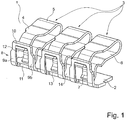
- Figure 1 shows a perspective view of a first embodiment of a spring clamp contact 1 which is essentially formed from a busbar 2 and several, for example three clamp springs 3 as shown.
- the busbar 2 is formed from a material with good electrical conductivity, such as, for example, from a copper sheet. It extends transversely to the direction of extension of the clamping springs 3 and in the rowing direction of the several clamping springs 3. In this way, the electrical conductor clamped to one clamping point of the busbar 2 with a clamping spring 3 can then be clamped to another clamp spring 3 of the spring clamp contact 1 in an electrically conductive manner electrical conductors are connected.
- the clamping springs 3 each have a contact leg 4, a spring bow 5 adjoining the contact leg 4 and a clamping leg 6 adjoining the spring bow 5.
- the clamping legs 6 each have a clamping section 7 at the free end on which a clamping edge is formed.
- associated frame parts 8 are formed for each clamping spring 3, each having two spaced-apart side webs 9a, 9b and an upper cross web 10 connecting the side webs 9a, 9b to one another at the free end.
- the transverse busbar 2 forms a further lower transverse web 11.
- the side webs 9a, 9b and the opposing cross webs 10, 11 create a conductor feed-through opening 12 for the passage of an electrical conductor which is attached to the clamping edge of the clamping section 7 of the associated clamping spring 3 and the contact edge 13 formed on the lower transverse web 11 of the busbar 2 is clamped.
- the clamping edge of the clamping section 7 of the clamping spring 3 and the contact edge 13 of the busbar 2 thus form a clamping point for the electrical conductor to be clamped.
- the frame parts 8 for the clamping springs 3 arranged next to one another are spaced apart from one another, forming an intermediate space 14 between frame parts 8 arranged next to one another.
- the adjacent side webs 9a, 9b of the frame parts 8 lying next to one another are spaced apart from one another.
- a section of an actuating element (not shown) for at least one associated clamping spring 3 can be introduced into this intermediate space 14, so that the space between the clamping springs 3 and in particular the space between the frame parts 8 can be used through the intermediate space 14 to accommodate sections of an actuating lever . This allows a very compact connecting terminal to be built.
- the clamping section 7 of the clamping spring 3 has a smaller width than the adjoining further section of the clamping leg 6 and the spring bow 5.
- the axis of rotation of this actuating lever is then located below the clamping leg 6 and the spring bow 5 in the space between the clamping leg 6 and busbar 2.
- the free end of the contact limb 4 also has a smaller width than the section of the contact limb 4 and the spring bow 5 adjoining the spring bow 5.
- This The reduced width of the contact leg 4 is adapted to the width of the conductor lead-through opening 12 of the frame part 8 in order to enable the contact leg 4 to be hooked into the conductor lead-through opening 2 for contact with the upper transverse web 10.
- Figure 2 omits a side view of the spring clamping contact 1 Figure 1 detect. It becomes clear that the rear free end of the contact leg 4 protrudes through the conductor lead-through opening 12 of the frame part 8 and is hooked into the frame part 8. It can also be seen that the frame part 8 is integrally formed in one piece with the busbar 2 from the same sheet metal part and is bent over from the plane of the busbar adjoining the clamping edge of the clamping spring 3 in the direction of the contact leg 4 of the clamping spring 3 at an angle of approximately 90 ° to 120 ° .
- the clamping leg 6 is bent at an internal angle of approximately 70 ° to 120 ° in the direction of the plane of the busbar 2 on which the clamping edge of the clamping section 7 rests in the illustrated idle state and is almost (+/- 20 °) is perpendicular to this plane. From this strongly bent section standing transversely to the conductor insertion direction, the clamping section 7 is then bent back to the free end to form a clamping edge and is at an acute angle to the aforementioned plane of the busbar 2 electrical conductor can be prevented without prior opening of the terminal point by shifting the clamping leg 6 upwards in the direction of the contact leg 4. Such direct insertion of a multi-wire electrical conductor without prior actuation could lead to the multiple wires of the electrical conductor being fanned out, which are then located in the connection space in an uncontrolled manner.
- Figure 3 omits a side sectional view through the first embodiment of the spring clamp contact Figure 1 and 2 detect. It becomes clear that the contact leg 4 is passed through the conductor lead-through opening 12 with a bent end section 15 and is in contact with the upper transverse web 10. The clamping spring 3 is thus suspended in a stable position in the busbar 2. The opposite end of the U-shaped bent clamping spring 3, ie the clamping section 7 of the clamping leg 4 is bent in the direction of the section of the busbar 2 which extends transversely to the number of clamping springs 3 and adjoins the frame parts 8, the free end of the Clamping section is at an acute angle to this transverse section of the busbar 2.
- An adjoining section of the clamping leg 6 that is approximately transversely to the conductor insertion direction L and the section of the busbar 2 is, however, aligned at an obtuse angle to the transverse section of the busbar 2 in order to prevent a multi-wire electrical conductor from being plugged in directly without prior actuation of the clamping spring 3 .
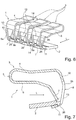
- Figure 4 shows a cross-sectional view of a connecting terminal 16 with an insulating material housing 17.
- the insulating housing 17 is made in two parts and has a main housing part 18 made of insulating material, which is closed with a cover part 20 after an actuating lever 19 and the spring terminal contact 1 have been inserted.
- the main housing part 18 and cover part 20 are locked together in order to mount the actuating lever 19 with a pivot bearing section 21, which has a part-circular periphery, on this part-circular periphery with matching part-circular bearing contours 22 in the insulating material housing 17.
- the pivot bearing section 21 can also be supported on the busbar 2.
- the pivot bearing section 21 has an actuating contour 23 in the form of a V-shaped cutout, which merges into the outer circumference via a curved path.
- the clamping leg 6 of the associated clamping spring 3 rests with a lateral area on this actuating contour 23, so that the clamping leg 6 is displaced away from the transverse section of the busbar 2 in the illustrated open position of the actuating lever 9.
- An electrical conductor can then be introduced via a conductor entry opening 24 in the insulating material housing 17, which is open at the end and opens into the connection space of the spring clamp contact 1. This is then passed over the inclined section of the busbar 2 extending transversely to the clamping springs 3 through the conductor lead-through opening 12 of the associated frame part 8 of the spring clamp contact 1. The free stripped end of an electrical conductor then arrives in a conductor receiving pocket 25, which is located behind the conductor feed-through opening 12 of the frame part 8 in the conductor guide direction L, i.e. in the direction of extension of the conductor insertion opening 24.
- Figure 5 omits the connecting terminal 16 Figure 4 detect when closed.
- the actuating lever 19 is folded down in the direction of the insulating housing 17.
- the actuating contour 23 has rotated here by pivoting the pivot bearing section 21 by approximately 90 °. This makes it possible for the clamping leg 6 to move away from the contact leg 4 downward in the direction of the busbar 2 by the force of the clamping spring 3. In the illustrated closed end position, the clamping leg 6 no longer rests on the actuating section 23, so that the clamping spring 3 can move unimpaired by the actuating lever 19.
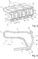
- FIG. 6 shows a perspective view of a second embodiment of a spring clamp contact 1 not according to the invention.
- a busbar 2 extends transversely to the direction in which several clamping springs 3 are arranged.
- a retaining lug 26 protrudes from the busbar 2 from the side edge of the busbar 2 in the conductor insertion direction L, that is, in the direction of extension of the contact leg 4 and the clamping leg 6 of the clamping springs 3 .
- a clamping point for clamping an electrical conductor is provided by a clamping edge on the free end of the clamping section 7 of the clamping spring 3 and a contact edge 13 on the associated retaining lug 26.
- An electrical conductor to be clamped is thus pressed by the force of the clamping spring 3 with the clamping edge on the clamping section 7 of the clamping spring 3 against the contact edge 13 on the opposite retaining lug 26.
- the force of the clamping spring 3 is concentrated on a defined, reduced contact area and the surface pressure is thus optimized.
- the frame parts 8 are now integrally formed in one piece with the associated clamping spring 3.
- the frame parts 8 are formed as an extension of the contact leg 4 and are bent from the contact leg 4 in the direction of the opposite, transverse section of the busbar 2.
- the frame parts 8 in turn have side webs 9a, 9b and at the free end a transverse web 11 which connects the side webs 9a, 9b to one another and which engages under the busbar 2.
- the clamping spring 3 is hooked into the busbar 2 and held on the busbar 2 by the force of the clamping spring via the clamping leg 6.
- an upper transverse web 10 is provided for connecting the frame parts 8, so that the transverse webs 10, 11 and the side webs 9a, 9b form a conductor feed-through opening 12 for passing an electrical conductor through.
- Figure 7 omits a side sectional view through the spring terminal contact 1 Figure 6 detect. It becomes clear that the transverse web 11 is folded or bent over at the free end of the frame part 8 and lies under the transverse section of the busbar 2.
- the retaining lug 26 is displaced downward out of the plane of the busbar 2, for example by pressing, in order to form a stop for the lower transverse web 11. In this way, the clamping spring 3 is locked on the busbar 2.
- a contact edge 13 for clamping an electrical conductor is created on the top of the busbar 2, on which the clamping force of the clamping spring 3 is concentrated.
- Figure 8 leaves a perspective view and Figure 9 a side sectional view of a third embodiment of a spring terminal contact 1 can be seen.
- several clamping springs 3 are lined up next to one another and hooked into a busbar 2.
- separate frame parts 8 are provided from the busbar 2 and the clamping spring 3, which frame parts are preferably formed from a sheet metal material.
- the task of the busbar 2 is comparable to the first embodiment.
- the retaining lug 26 is displaced downward relative to the underside of the busbar 2 in order to form a stop for the lower transverse web 11 of the frame part 8.
- no free space with a shoulder for forming a clamping edge 13 is provided.
- the busbar runs obliquely from the upper level, so that a clamping edge 13 is formed in the transition between the upper level of the busbar 2 and the obliquely tapering end.
- the busbar 2 it is also conceivable to use the busbar 2 from the second exemplary embodiment in the present solution.
- the first and second embodiment are combined in such a way that, with the help of the separate frame parts 8, the contact leg 4 of the associated clamping spring 3 is hooked into the upper crossbar 10 and the busbar 2 is hooked into the lower crossbar 11 with the help of the retaining lug 26.
- the frame parts 8 have two spaced-apart side webs 9a, 9b and at the two opposite ends cross webs 10, 11 that connect the side webs 9a, 9b to one another, in order to create a circumferentially closed frame with a conductor opening 12 formed in between.
- the frame parts 8 are arranged at a distance from one another on the busbar 2 with an intermediate space 14. It is irrelevant whether the frame parts are formed in one piece, integrally with the busbar 2 or with an associated clamping spring 3, or are designed as a separate component from the busbar 2 and the clamping springs 3.
- the spring clamp contact 1 and a connecting terminal 16 equipped with such a spring clamp contact 1 can also be designed in two rows. Two parallel conductor connection planes spaced apart from one another are provided in that frame parts 8 extend in opposite directions to one another.
- a double-layer busbar 2 can be provided which has integrally formed frame parts 8 extending in opposite directions.
- separate frame parts can also be accommodated in a space between the double-layer busbar. It is also conceivable, however, for conductor connections to be lined up next to one another with frame parts 8 alternately oriented in opposite directions on a busbar 2.
- a two-row connecting terminal 16 can also be created by having at least one clamping spring 3 above and below the busbar with an orientation rotated by 180 ° to each other and, on the one hand, in the space above and on the other hand in the space below the busbar 2, frame parts 8 on opposite outer edges the busbar 2 are provided.
Landscapes
- Installation Of Bus-Bars (AREA)
- Connections Arranged To Contact A Plurality Of Conductors (AREA)
- Railway Tracks (AREA)
Description
- Die Erfindung betrifft einen Federklemmkontakt gemäß dem Oberbegriff des Anspruchs 1.
Die Erfindung betrifft weiterhin eine Verbindungsklemme für elektrische Leiter mit einem Isolierstoffgehäuse und mit mindestens einem solchen Federklemmkontakt. - Solche Federklemmkontakte werden in Verbindungsklemmen, insbesondere in Dosenklemmen zur elektrisch leitenden Verbindung mehrerer elektrischer Leiter miteinander, in Leiterplattensteckverbindern, sonstigen Steckverbindern und Reihenklemmen oder sonstigen elektrischen Geräten genutzt.
- Aus
DE 10 2007 017 593 B4 ist eine Verbindungsklemme mit einem Federstahlblech bekannt, aus dem spiegelsymmetrisch zu einer Mittenebene zwei Blattfederzungen freigeschnitten sind. Ein Stromschienenstab liegt in der Mittenebene an dem Stück Federstahlblech an. - Weiterhin ist aus
DE 102 37 701 B4 eine hebelbetätigte Verbindungsklemme bekannt, bei der eine Käfigzugfeder mit ihrem Anlageschenkel auf einem Stromschienenstück aufliegt, das durch eine Leiterdurchführungsöffnung der Käfigzugfeder hindurchragt. Der Hebel beaufschlagt einen Betätigungsabschnitt der Käfigzugfeder von oben, wobei von dem Betätigungsabschnitt der die Leiterdurchführungsöffnung aufweisende Klemmabschnitt quer zum Stromschienenstück weggebogen ist. - Aus
DE 196 54 611 B4 ist weiterhin bekannt, eine U-förmig gebogene Blattfeder in eine Leiterdurchführungsöffnung eines Stromschienenstücks einzuhängen. Das Stromschienenstück besitzt hierzu einen Halteschenkel und einen Kontaktschenkel, die miteinander einen Eckwinkel bilden, derart, dass der Halteschenkel, der zur Halterung der Blattfeder dient, mit seinem Rücken querstehend zur Leitereinführungsrichtung angeordnet ist und einen Durchbruch zum Hindurchstecken des elektrischen Leiters aufweist, und dass der Kontaktschenkel direkt am Scheitel des Eckwinkels des Haltewinkels anschließt und sich von diesem in Leitereinführungsrichtung hinweg erstreckt. - In der
DE 10 2010 024 809 A1 ist eine hebelbetätigte Anschlussklemme mit einem Isolierstoffgehäuse und einer Federklemmeinheit mit einer Klemmfeder und einem Stromschienenabschnitt beschrieben. Die Klemmfeder hat einen Anlageabschnitt, der in einem vom Stromschienenabschnitt wegragenden Bügel eingehängt ist und eine Leiterdurchführungsöffnung aufweist. Die Klemmfeder hat weiter einen zum Anklemmen eines elektrischen Leiters gegen den Stromschienenabschnitt ausgeformten Klemmabschnitt und einen hiervon abragenden Betätigungsabschnitt, der sich von der Richtung der am Klemmabschnitt wirkenden Federkraft der Klemmfeder weg erstreckt und zur Beaufschlagung durch ein Betätigungselement so ausgerichtet ist, dass das Betätigungselement zur Ausübung einer auf dem Betätigungsabschnitt bei Verlagerung des Betätigungselementes entgegen der Federkraft wirkenden Zugkraft zum Öffnen der Klemmfeder mit dem Betätigungsabschnitt in Eingriff bringbar ist. - Aus der
US 2005/0042912 A1 ist eine elektrische Verbindungsanordnung mit Klemmfedern bekannt, die einstückig angeformte Rahmenteile aufweisen. - Ausgehend hiervon ist es Aufgabe der vorliegenden Erfindung, einen verbesserten Federklemmkontakt zur Kontaktierung elektrischer Leiter sowie eine verbesserte Verbindungsklemme für elektrische Leiter zu schaffen.
- Die Aufgabe wird durch den Federklemmkontakt mit den Merkmalen des Anspruchs 1 sowie durch die Verbindungsklemme mit den Merkmalen des Anspruchs 9 gelöst.
- Für einen gattungsgemäßen Federklemmkontakt wird vorgeschlagen, dass die mindestens zwei Rahmenteile für die mindestens zwei Klemmfedern mit einem Zwischenraum zwischen zwei benachbarten Seitenstegen nebeneinander angeordneter Rahmenteile beabstandet voneinander sind.
- Durch den Abstand zwischen zwei benachbarten Seitenstege nebeneinander angeordneter Rahmenteile wird ein Freiraum geschaffen, in dem vorzugsweise ein Betätigungselement, wie beispielsweise ein schwenkbar in einem Isolierstoffgehäuse angeordneter Betätigungshebel und/oder ein Gehäusewandabschnitt angeordnet werden kann. Auf diese Weise wird erreicht, dass unter Einhaltung der erforderlichen Luft- und Kriechstrecken bei sehr kompakter Ausführung eines Federklemmkontakts eine sehr kompakte Verbindungsklemme realisiert werden kann.
- Die Rahmenteile sind in einer bevorzugten Ausführungsform einstückig mit der Stromschiene geformt. Hierzu sind zur Bildung von Seitenstegen und einem Quersteg Leiterdurchführungsöffnungen aus einem Stromschienenblech ausgestanzt und vor oder nach dem Schritt des Ausstanzens die Seitenstege zusammen mit dem diesen verbindenden Quersteg, d. h. die Rahmenteile, von einer Klemmkontaktfläche der Stromschiene in einem spitzen oder stumpfen Winkel weggebogen. Der Winkel zwischen der Stromschienenebene, auf der die Klemmstelle gebildet wird, und der Rahmenteile beträgt vorzugsweise etwa 60 bis 120 Grad.
- Denkbar ist aber auch eine Ausführungsform, bei der die Rahmenteile an einem von der Stromschiene separaten Rahmenelement ausgebildet sind, wobei das Rahmenelement in die Stromschiene eingehängt ist. Das Rahmenelement wird hierbei durch die Kraft der zwischen dem Quersteg und der Rahmenteile des Rahmenelementes und der Stromschiene wirkenden Klemmfedern an der Stromschiene gehalten, indem das Rahmenelement die Stromschiene vorzugsweise untergreift. Hierzu können an der Stromschiene Halteelemente in Form von Haltenasen vorgesehen sein, die von Querstegen des Rahmenelementes untergriffen werden. Denkbar ist aber auch, dass die Stromschiene Rastöffnungen oder Rastmulden hat, in die Rastfinger des Rahmenelementes eingreifen, um das Rahmenelement mit der Stromschiene (lösbar) zu verbinden.
- Zur Bildung einer Klemmstelle für einen elektrischen Leiter ist der Klemmabschnitt einer Klemmfeder bevorzugt von dem sich an dem Federbogen anschließenden Abschnitt des Klemmschenkels in Richtung zur Stromschiene weg umgebogen oder abgeknickt. Dabei kann das sichere Anklemmen eines elektrischen Leiters durch die Klemmfeder verbessert und gleichzeitig sichergestellt werden, dass der elektrische Leiter ohne vorherige Betätigung der Klemmfeder an die Klemmstelle anschließbar ist.
- Weiterhin ist es vorteilhaft, wenn der Klemmabschnitt eine geringere Breite als der übrige Abschnitt des Klemmschenkels hat. Dies ist insbesondere vorteilhaft, weil der mindestens eine relativ zum Klemmabschnitt seitlich überstehende Bereich des in Bezug auf den Klemmabschnitt breiteren Abschnitts des Klemmschenkels als Betätigungsabschnitt zum Öffnen einer zwischen Klemmabschnitt der Klemmfeder und der Stromschiene gebildeten Klemmstelle für einen elektrischen Leiter mit einem Betätigungselement geöffnet werden kann, das mit dem Betätigungsabschnitt zusammen wirkt und in den Zwischenraum zwischen zwei Rahmenteilen hineinragt.
- Die Erfindung wird nachfolgend anhand eines Ausführungsbeispiels mit den beigefügten Zeichnungen näher erläutert. Es zeigen:
- Figur 1
- - perspektivische Ansicht einer ersten erfindungsgemäßen Ausführungsform eines Federklemmkontaktes mit Stromschiene und drei nebeneinander angeordneten Klemmfedern;
- Figur 2
- - Seitenansicht des Federklemmkontaktes aus
Figur 1 ; - Figur 3
- - Seiten-Schnittansicht des Federklemmkontaktes aus
Figur 1 ; - Figur 4
- - Seiten-Schnittansicht durch eine Verbindungsklemme mit einem Isolierstoffgehäuse, hier einem Betätigungshebel für eine zugeordnete Klemmfeder und einem in das Isolierstoffgehäuse eingebauten Federklemmkontakt aus
Figur 1 mit geöffnetem Betätigungshebel; - Figur 5
- - Seiten-Schnittansicht durch die Verbindungsklemme aus Figur 4 mit geschlossenem Betätigungshebel;
- Figur 6
- - perspektivische Ansicht einer zweiten nicht erfindungsgemäßen Ausführungsform eines Federklemmkontaktes;
- Figur 7
- - Seiten-Schnittansicht durch den Federklemmkontakt aus Figur 6;
- Figur 8
- - perspektivische Ansicht einer dritten erfindungsgemäßen Ausführungsform eines Federklemmkontaktes;
- Figur 9
- - Seiten-Schnittansicht durch den Federklemmkontakt aus Figur 8.
-
Figur 1 lässt eine perspektivische Ansicht einer ersten Ausführungsform eines Federklemmkontaktes 1 erkennen, der im Wesentlichen aus einer Stromschiene 2 und mehreren, z.B. wie dargestellt drei Klemmfedern 3 gebildet ist. Die Stromschiene 2 ist aus einem elektrisch gut leitendem Material, wie beispielsweise aus einem Kupferblech gebildet. Sie erstreckt sich quer zur Erstreckungsrichtung der Klemmfedern 3 und in Anreihrichtung der mehreren Klemmfedern 3. Auf diese Weise kann dann der mit einer Klemmfeder 3 an eine Klemmstelle der Stromschiene 2 angeklemmte elektrische Leiter elektrisch leitend mit einem weiteren an einer anderen Klemmfeder 3 des Federklemmkontaktes 1 angeklemmten elektrischen Leiter verbunden werden. - Die Klemmfedern 3 haben jeweils einen Anlageschenkel 4, einen sich an den Anlegeschenkel 4 anschließenden Federbogen 5 und einen sich an den Federbogen 5 anschließenden Klemmschenkel 6. Die Klemmschenkel 6 haben jeweils einen Klemmabschnitt 7 am freien Ende, an dem eine Klemmkante ausgebildet ist. Mit der Stromschiene 2 sind für jede Klemmfeder 3 zugeordnete Rahmenteile 8 ausgeformt, die jeweils zwei voneinander beabstandete Seitenstege 9a, 9b und einen oberen, die Seitenstege 9a, 9b am freien Ende miteinander verbindenden Quersteg 10 haben. Gegenüberliegend zum oberen Quersteg 10 bildet die quer verlaufende Stromschiene 2 einen weiteren unteren Quersteg 11. Durch die Seitenstege 9a, 9b und die einander gegenüberliegenden Querstege 10, 11 wird eine Leiterdurchführungsöffnung 12 zum Durchführen eines elektrischen Leiters geschaffen, der an die Klemmkante des Klemmabschnitts 7 der zugeordneten Klemmfeder 3 und der an dem unteren Quersteg 11 der Stromschiene 2 gebildeten Kontaktkante 13 angeklemmt wird. Die Klemmkante des Klemmabschnitts 7 der Klemmfeder 3 und die Kontaktkante 13 der Stromschiene 2 bilden somit eine Klemmstelle für den anzuklemmenden elektrischen Leiter.
- Deutlich wird, dass die Rahmenteile 8 für die nebeneinander angeordneten Klemmfedern 3 unter Bildung eines Zwischenraums 14 zwischen nebeneinander angeordneten Rahmenteile 8 voneinander beabstandet sind. Die benachbarten Seitenstege 9a, 9b der nebeneinander liegenden Rahmenteile 8 haben einen Abstand voneinander. In diesem Zwischenraum 14 ist ein Abschnitt eines Betätigungselementes (nicht gezeigt) für mindestens einen zugeordnete Klemmfeder 3 einbringbar, so dass der Raum zwischen den Klemmfedern 3 und insbesondere der Raum zwischen den Rahmenteilen 8 durch den Zwischenraum 14 zur Aufnahme von Abschnitten eines Betätigungshebels genutzt werden kann. Damit kann eine sehr kompakte Verbindungsklemme aufgebaut werden.
- Erkennbar ist weiterhin, dass der Klemmabschnitt 7 der Klemmfeder 3 eine geringere Breite als der sich daran anschließende weitere Abschnitt des Klemmschenkels 6 und des Federbogens 5 hat. Damit ist ein relativ zum Klemmabschnitt 7 seitlich überstehende Bereich des Klemmschenkels 6 vorhanden, auf den eine Betätigungskontur eines Betätigungshebels wirken kann, wobei die Betätigungskontur an einem Seitenwandabschnitt eines zumindest im geschlossenen Zustand in den Zwischenraum 14 hineinragenden Betätigungshebels angeordnet ist. Die Drehachse dieses nicht dargestellten Betätigungshebels befindet sich dann unterhalb des Klemmschenkels 6 und des Federbogens 5 im Zwischenraum zwischen Klemmschenkel 6 und Stromschiene 2.
- Erkennbar ist weiterhin, dass das freie Ende des Anlageschenkels 4 ebenfalls eine geringere Breite als der sich an den Federbogen 5 anschließende Abschnitt des Anlageschenkels 4 und des Federbogens 5 hat. Diese verringerte Breite des Anlageschenkels 4 ist an die Breite der Leiterdurchführungsöffnung 12 des Rahmenteils 8 angepasst, um ein Einhängen des Anlageschenkels 4 in die Leiterdurchführungsöffnung 2 zur Anlage an dem oberen Quersteg 10 zu ermöglichen.
-
Figur 2 lässt eine Seitenansicht des Federklemmkontakts 1 ausFigur 1 erkennen. Dabei wird deutlich, dass das hintere freie Ende des Anlageschenkels 4 durch die Leiterdurchführungsöffnung 12 des Rahmenteils 8 hindurchragt und in das Rahmenteil 8 eingehängt ist. Erkennbar ist weiterhin, dass das Rahmenteil 8 einstückig integral mit der Stromschiene 2 aus demselben Blechteil ausgeformt und von der an die Klemmkante der Klemmfeder 3 angrenzenden Ebene der Stromschiene in Richtung Anlageschenkel 4 der Klemmfeder 3 in einem Winkel von etwa 90° bis 120° umgebogen ist. - Erkennbar ist weiterhin, dass der Klemmschenkel 6, in einem Innenwinkel von etwa 70° bis 120° in Richtung der Ebene der Stromschiene 2, auf der im dargestellten Ruhezustand die Klemmkante des Klemmabschnitts 7 aufliegt, umgebogen ist und nahezu (+/- 20°) lotrecht auf dieser Ebene steht. Von diesem stark umgebogenen quer zur Leitereinsteckrichtung stehenden Abschnitt ist der Klemmabschnitt 7 dann zum freien Ende hin zur Bildung einer Klemmkante wieder zurückgebogen und steht im spitzen Winkel zu der vorgenannten Ebene der Stromschiene 2. Auf diese Weise kann ein direktes Anklemmen eines in Leitereinstreckrichtung L eingeführten mehrdrahtigen elektrischen Leiters ohne vorheriges Öffnen der Klemmstelle durch Verlagerung des Klemmschenkels 6 nach oben in Richtung Anlageschenkel 4 verhindert werden. Ein solches direktes Einstecken eines mehrdrahtigen elektrischen Leiters ohne vorherige Betätigung könnte zu einem Aufspleißen der mehreren Drähte des elektrischen Leiters führen, die sich dann unkontrolliert im Anschlussraum befinden.
-
Figur 3 lässt eine Seiten-Schnittansicht durch die erste Ausführungsform des Federklemmkontaktes ausFigur 1 und2 erkennen. Dabei wird deutlich, dass der Anlageschenkel 4 mit einem umgebogenen Endabschnitt 15 durch die Leiterdurchführungsöffnung 12 hindurchgeführt ist und an dem oberen Quersteg 10 anliegt. Die Klemmfeder 3 ist somit lagestabil in die Stromschiene 2 eingehängt. Das gegenüberliegende Ende der U-förmig gebogenen Klemmfeder 3, d.h. der Klemmabschnitt 7 des Klemmschenkels 4 ist in Richtung des sich quer zu der Anzahl von Klemmfedern 3 erstreckenden Abschnitts der Stromschiene 2, der an die Rahmenteile 8 angrenzt, abgebogen, wobei das freie Ende des Klemmabschnitts im spitzen Winkel zu diesem quer verlaufenden Abschnitt der Stromschiene 2 steht. Ein sich daran anschließender annähernd quer zur Leitereinführungsrichtung L und dem Abschnitt der Stromschiene 2 stehender Abschnitt des Klemmschenkels 6 ist hingegen im stumpfen Winkel zu dem quer verlaufenden Abschnitt der Stromschiene 2 ausgerichtet, um ein Direktstecken eines mehrdrahtigen elektrischen Leiters ohne vorherige Betätigung der Klemmfeder 3 zu verhindern. -
Figur 4 lässt eine Querschnittsansicht einer Verbindungsklemme 16 mit einem Isolierstoffgehäuse 17 erkennen. Das Isolierstoffgehäuse 17 ist zweiteilig ausgeführt und hat ein aus Isolierstoffmaterial gebildetes Hauptgehäuseteil 18, das nach Einsetzen eines Betätigungshebels 19 und des Federklemmkontaktes 1 mit einem Deckelteil 20 verschlossen wird. Hauptgehäuseteil 18 und Deckelteil 20 werden dabei miteinander verrastet, um auf diese Weise den Betätigungshebel 19 mit einem Schwenklagerabschnitt 21, der einen teilkreisförmigen Umfang hat, an diesem teilkreisförmigen Umfang mit hieran angepassten teilkreisförmigen Lagerkonturen 22 im Isolierstoffgehäuse 17 zu lagern. Der Schwenklagerabschnitt 21 kann dabei auch auf der Stromschiene 2 aufgelagert sein. - Deutlich wird, dass der Schwenklagerabschnitt 21 eine Betätigungskontur 23 in Form eines V-förmigen Ausschnitts hat, der über eine gekrümmte Bahn in den Außenumfang übergeht. Der Klemmschenkel 6 der zugeordneten Klemmfeder 3 liegt dabei mit einem seitlichen Bereich auf dieser Betätigungskontur 23 auf, so dass der Klemmschenkel 6 in der dargestellten Offenstellung des Betätigungshebels 9 von dem quer verlaufenden Abschnitt der Stromschiene 2 weg verlagert ist.
- Dann kann über eine Leitereinführungsöffnung 24 in dem Isolierstoffgehäuse 17, die stirnseitig offen ist und in dem Anschlussraum des Federklemmkontaktes 1 mündet, ein elektrischer Leiter eingeführt werden. Dieser wird dann über den geneigt verlaufenden, sich quer zu den Klemmfedern 3 erstreckenden Abschnitt der Stromschiene 2 durch die Leiterdurchführungsöffnung 12 des zugeordneten Rahmenteils 8 des Federklemmkontakts 1 geführt. Das freie abisolierte Ende eines elektrischen Leiters gelangt dann in eine Leiteraufnahmetasche 25, die in Leiterführungsrichtung L, d.h. in Erstreckungsrichtung der Leitereinführungsöffnung 24 gesehen, hinter der Leiterdurchführungsöffnung 12 des Rahmenteils 8 liegt.
-
Figur 5 lässt die Verbindungsklemme 16 ausFigur 4 im geschlossenen Zustand erkennen. Hierbei ist der Betätigungshebel 19 nach unten in Richtung Isolierstoffgehäuse 17 heruntergeklappt. Die Betätigungskontur 23 hat sich hierbei durch Verschwenken des Schwenklagerabschnitts 21 um etwa 90° gedreht. Dabei wird ermöglicht, dass der Klemmschenkel 6 durch die Kraft der Klemmfeder 3 sich vom Anlageschenkel 4 weg nach unten in Richtung Stromschiene 2 verlagert. In der dargestellten geschlossenen Endposition liegt der Klemmschenkel 6 nicht mehr auf dem Betätigungsabschnitt 23 auf, so dass sich die Klemmfeder 3 unbeeinträchtigt durch den Betätigungshebel 19 bewegen kann. Damit wird ein nicht dargestellter in die Leitereinführungsöffnung 24 eingeführter elektrischer Leiter durch die Kraft der Klemmfeder 3 mit der Klemmkante am freien Klemmabschnitt 7 und die Kontaktkante 13 an der Stromschiene 2 elektrisch leitend und mechanisch festgeklemmt, so dass ein elektrischer Strom über den elektrischen Leiter und die Stromschiene 2 zu einem benachbarten Klemmkontakt geführt werden kann. -
Figur 6 lässt eine perspektivische Ansicht einer zweiten nicht erfindungsgemäßen Ausführungsform eines Federklemmkontaktes 1 erkennen. Auch hier erstreckt sich eine Stromschiene 2 quer zur Anreihrichtung mehrerer Klemmfedern 3. Für jede Klemmfeder 3 ragt von der Stromschiene 2 jeweils eine Haltenase 26 von der Seitenkante der Stromschiene 2 in Leitereinsteckrichtung L, d.h. in Erstreckungsrichtung von Anlageschenkel 4 und Klemmschenkel 6 der Klemmfedern 3 ab. - Bei dieser Ausführungsform wird eine Klemmstelle für das Anklemmen eines elektrischen Leiters durch eine Klemmkante am freien Ende des Klemmabschnitts 7 der Klemmfeder 3 und eine Kontaktkante 13 an der zugeordneten Haltenase 26 bereitgestellt. Ein anzuklemmender elektrischer Leiter wird somit durch die Kraft der Klemmfeder 3 mit der Klemmkante an den Klemmabschnitt 7 der Klemmfeder 3 gegen die Kontaktkante 13 an der gegenüberliegenden Haltenase 26 gedrückt. Auf diese Weise wird die Kraft der Klemmfeder 3 auf einen definierten reduzierten Kontaktbereich konzentriert und so die Flächenpressung optimiert.
- In dem dargestellten Ausführungsbeispiel sind die Rahmenteile 8 nunmehr einstückig integral mit der zugeordneten Klemmfeder 3 geformt. Dabei sind die Rahmenteile 8 als Verlängerung des Anlageschenkels 4 gebildet und vom Anlageschenkel 4 in Richtung des gegenüberliegenden quer verlaufenden Abschnitts der Stromschiene 2 gebogen. Die Rahmenteile 8 haben wiederum Seitenstege 9a, 9b und am freien Ende einen die Seitenstege 9a, 9b miteinander verbindenen Quersteg 11, der die Stromschiene 2 untergreift. Mit Hilfe dieses Querstegs 11 wird die Klemmfeder 3 in die Stromschiene 2 eingehängt und durch die Kraft der Klemmfeder über den Klemmschenkel 6 an der Stromschiene 2 gehalten.
- Durch den Übergang der Rahmenteile 8 in den sich daran anschließenden Anlageschenkel 4 wird ein oberer Quersteg 10 zur Verbindung der Rahmenteile 8 bereitgestellt, so dass die Querstege 10, 11 und die Seitenstege 9a, 9b eine Leiterdurchführungsöffnung 12 zum Durchführen eines elektrischen Leiters bilden.
-
Figur 7 lässt eine Seiten-Schnittansicht durch den Federklemmkontakt 1 ausFigur 6 erkennen. Deutlich wird, dass der Quersteg 11 am freien Ende des Rahmenteils 8 umgefaltet bzw. umgebogen ist und unter dem quer verlaufenden Abschnitt der Stromschiene 2 liegt. Die Haltenase 26 ist dabei aus der Ebene der Stromschiene 2 z.B. durch Pressen nach unten verlagert, um einen Anschlag für den unteren Quersteg 11 zu bilden. Auf diese Weise wird die Klemmfeder 3 an der Stromschiene 2 arretiert. Durch die Verlagerung der Haltenase 26 nach unten wird an der Oberseite der Stromschiene 2 eine Kontaktkante 13 zum Anklemmen eines elektrischen Leiters geschaffen, auf den die Klemmkraft der Klemmfeder 3 konzentriert wird. Deutlich wird, dass der Klemmabschnitt 7 am freien Ende des Klemmschenkels 6 der Klemmfeder 3 in den durch Verlagerung der Haltenase 26 nach unten geschaffenen Freiraum eintaucht und an der Stirnseite 2 der Stromschiene 2 bzw. der Klemmkante 13 anliegt. Damit wird ein selbsttragendes Systems von Stromschiene 2 und Klemmfeder 3 geschaffen, das derartig vormontiert in das Isolierstoffgehäuse 17 einer Verbindungsklemme 16 eingelegt werden kann. -
Figur 8 lässt eine perspektivische Ansicht undFigur 9 eine Seiten-schnittansicht einer dritten Ausführungsform eines Federklemmkontaktes 1 erkennen. Auch hier sind wiederum mehrere Klemmfedern 3 nebeneinander aufgereiht und in eine Stromschiene 2 eingehängt. Bei dieser Ausführungsform sind von der Stromschiene 2 und der Klemmfeder 3 separate Rahmenteile 8 vorgesehen, die bevorzugt aus einem Blechmaterial ausgeformt sind. Der Aufgabe der Stromschiene 2 ist zur ersten Ausführungsform vergleichbar. Auch hier ist die Haltenase 26 gegenüber der Unterseite der Stromschiene 2 nach unten verlagert, um einen Anschlag für den unteren Quersteg 11 des Rahmenteils 8 zu bilden. Im Unterschied zur zweiten Ausführungsform ist allerdings kein Freiraum mit einem Absatz zur Bildung einer Klemmkante 13 vorgesehen. Vielmehr läuft die Stromschiene von der oberen Ebene schräg aus, so dass eine Klemmkante 13 in dem Übergang zwischen der oberen Ebene der Stromschiene 2 und dem schräg auslaufendem Ende gebildet wird. Denkbar ist aber auch die Verwendung der Stromschiene 2 aus dem zweiten Ausführungsbeispiel bei der vorliegenden Lösung. - In der dritten Ausführungsform wird die erste und zweite Ausführungsform derart kombiniert, dass mit Hilfe der separaten Rahmenteile 8 der Anlageschenkel 4 der zugeordneten Klemmfeder 3 in den oberen Quersteg 10 und die Stromschiene 2 in den unteren Quersteg 11 mit Hilfe der Haltenase 26 eingehängt wird. Auch hier haben die Rahmenteile 8 zwei voneinander beabstandete Seitenstege 9a, 9b und an den beiden gegenüberliegenden Enden die Seitenstege 9a, 9b miteinander verbindende Querstege 10, 11, um auf diese Weise einen umlaufend geschlossenen Rahmen mit einer dazwischen gebildeten Leiterdurchführungsöffnung 12 zu schaffen.
- Bei allen drei Ausführungsformen ist vorgesehen, dass die Rahmenteile 8 mit einem Zwischenraum 14 voneinander beabstandet an der Stromschiene 2 angeordnet sind. Unerheblich ist dabei, ob die Rahmenteile einstückig, integral mit der Stromschiene 2 oder mit einer zugeordneten Klemmfeder 3 ausgeformt oder als zur Stromschiene 2 und den Klemmfedern 3 separates Bauteil ausgeführt sind.
- Der Federklemmkontakt 1 und eine mit einem solchen Federklemmkontakt 1 ausgestattete Verbindungsklemme 16 lässt sich auch zweireihig ausführen. Dabei sind zwei voneinander beabstandete parallele Leiteranschlussebenen vorgesehen, indem sich Rahmenteile 8 in entgegengesetzte Richtungen zueinander erstrecken. Hierzu kann eine doppellagige Stromschiene 2 vorgesehen sein, die sich in entgegengesetzte Richtung erstreckende, integral geformte Rahmenteile 8 haben. Es können aber auch separate Rahmenteile in einen Raum zwischen der doppellagigen Stromschiene aufgenommen sein. Denkbar ist aber auch, dass Leiteranschlüsse nebeneinander mit alternierend in entgegengesetzte Richtung ausgerichteten Rahmenteilen 8 auf einer Stromschiene 2 aufgereiht sind. Eine zweireihige Verbindungsklemme 16 lässt sich auch dadurch schaffen, dass oberhalb und unterhalb der Stromschiene jeweils mindestens eine Klemmfeder 3 mit um 180° zueinander gedrehter Ausrichtung und einerseits in den Raum oberhalb und andererseits in den Raum unterhalb der Stromschiene 2 ausrichteten Rahmenteilen 8 an einander gegenüberliegenden Aussenkanten der Stromschiene 2 vorgesehen sind.
Claims (9)
- Federklemmkontakt (1) zur Kontaktierung elektrischer Leiter mit einer Stromschiene (2) und mit mindestens zwei Klemmfedern (3), die jeweils einen Anlageschenkel (4), einen sich an den Anlageschenkel (4) anschließenden Federbogen (5) und einen sich an den Federbogen (5) anschließenden Klemmschenkel (6) mit einem Klemmabschnitt (7) am freien Ende haben, wobei zwischen dem jeweiligen Klemmabschnitt (7) und der Stromschiene (2) eine Klemmstelle zum Anklemmen eines elektrischen Leiters gebildet ist, und mit sich von der Stromschiene (2) weg erstreckenden Rahmenteilen (8), die jeweils zwei voneinander beabstandete Seitenstege (9a, 9b) und die Seitenstege (9a, 9b) miteinander verbindende Querstege (10, 11) und eine durch die Seitenstege (9a, 9b) und die Querstege (10, 11) gebildete Leiterdurchführungsöffnung (12) haben, wobei eine Klemmfeder (3) an der Stromschiene (2) durch Anlage des Anlageschenkels (4) der Klemmfeder (3) an einem Quersteg (10, 11) befestigt ist und der Klemmabschnitt (7) unter der Federkraft der Klemmfeder (3) in Richtung der Stromschiene (2) wirkt, dadurch gekennzeichnet, dass die mindestens zwei Rahmenteile (8) für die mindestens zwei Klemmfedern (3) mit einem Zwischenraum (14) zwischen zwei beabstandeten Seitenstegen (9a, 9b) nebeneinander angeordneter Rahmenteile (8) beabstandet voneinander sind.
- Federklemmkontakt (1) nach Anspruch 1, dadurch gekennzeichnet, dass die Rahmenteile (8) einstückig mit der Stromschiene (2) geformt sind.
- Federklemmkontakt (1) nach Anspruch 1, dadurch gekennzeichnet, dass die Rahmenteile (8) als mindestens ein von der Stromschiene (2) separates Rahmenelement ausgebildet sind und das separate Rahmenelement in die Stromschiene (2) eingehängt ist.
- Federklemmkontakt (1) nach Anspruch 3, dadurch gekennzeichnet, dass die Stromschiene (2) Haltenasen (26) als Halteelement für die Rahmenteile (8) hat und das Rahmenteil (8) mit einem Quersteg (11) die Haltenasen (26) der Stromschiene (2) untergreift.
- Federklemmkontakt (1) nach Anspruch 3 oder 4, dadurch gekennzeichnet, dass die Stromschiene (2) Rastöffnungen oder Rastmulden hat und dass das Rahmenteil (8) in zugeordnete Rastöffnungen oder Rastmulden eintauchende Rastfinger aufweist.
- Federklemmkontakt (1) nach einem der vorhergehenden Ansprüche, dadurch gekennzeichnet, dass der Klemmabschnitt (7) von dem sich an den Federbogen (5) anschließenden Abschnitt des Klemmschenkels (6) in Richtung zur Stromschiene (2) weg umgebogen oder abgeknickt ist.
- Federklemmkontakt (1) nach einem der vorhergehenden Ansprüche, dadurch gekennzeichnet, dass der Klemmabschnitt (7) eine geringere Breite als der übrige Abschnitt des Klemmschenkels (6) hat.
- Federklemmkontakt (1) nach Anspruch 7, dadurch gekennzeichnet, dass mindestens ein relativ zum Klemmabschnitt (7) seitlich überstehender Bereich des in Bezug auf den Klemmabschnitt (7) breiteren Abschnitts des Klemmschenkels (6) als Betätigungsabschnitt zum Öffnen einer zwischen dem Klemmabschnitt (7), der Klemmfeder (3) und der Stromschiene (2) gebildeten Klemmstelle für einen elektrischen Leiter durch ein mit dem Betätigungsabschnitt zusammenwirkendes Betätigungselement vorgesehen ist.
- Verbindungsklemme (16) für elektrische Leiter mit einem Isolierstoffgehäuse (17) und mit mindestens einem Federklemmkontakt (1) nach einem der vorhergehenden Ansprüche, dadurch gekennzeichnet, dass mindestens ein Betätigungselement (19) beweglich in das Isolierstoffgehäuse (17) eingebracht ist, wobei das mindestens eine Betätigungselement (19) in einen zugeordneten Zwischenraum (14) zwischen zwei benachbarten Seitenstegen (9a, 9b) nebeneinander angeordneter Rahmenteile (8) hineinragt und eine Kontur zur Beaufschlagung mindestens einer Klemmfeder (3) zum Öffnen einer zwischen dem Klemmabschnitt der Klemmfeder (3) und der Stromschiene (2) gebildeten Klemmstelle zum Anklemmen eines elektrischen Leiters hat.
Priority Applications (1)
| Application Number | Priority Date | Filing Date | Title |
|---|---|---|---|
| PL14704143T PL2956993T3 (pl) | 2013-02-13 | 2014-02-12 | Złączka z zaciskiem sprężynowym i zacisk przyłączeniowy dla przewodów elektrycznych |
Applications Claiming Priority (2)
| Application Number | Priority Date | Filing Date | Title |
|---|---|---|---|
| DE202013100635U DE202013100635U1 (de) | 2013-02-13 | 2013-02-13 | Federklemmkontakt und Verbindungsklemme für elektrische Leiter |
| PCT/EP2014/052719 WO2014124961A1 (de) | 2013-02-13 | 2014-02-12 | Federklemmkontakt und verbindungsklemme für elektrische leiter |
Publications (2)
| Publication Number | Publication Date |
|---|---|
| EP2956993A1 EP2956993A1 (de) | 2015-12-23 |
| EP2956993B1 true EP2956993B1 (de) | 2021-04-07 |
Family
ID=48051756
Family Applications (1)
| Application Number | Title | Priority Date | Filing Date |
|---|---|---|---|
| EP14704143.8A Active EP2956993B1 (de) | 2013-02-13 | 2014-02-12 | Federklemmkontakt und verbindungsklemme für elektrische leiter |
Country Status (10)
| Country | Link |
|---|---|
| US (1) | US9502790B2 (de) |
| EP (1) | EP2956993B1 (de) |
| JP (1) | JP6400607B2 (de) |
| KR (1) | KR102145876B1 (de) |
| CN (1) | CN104995798B (de) |
| DE (1) | DE202013100635U1 (de) |
| ES (1) | ES2871850T3 (de) |
| PL (1) | PL2956993T3 (de) |
| RU (1) | RU2597003C1 (de) |
| WO (1) | WO2014124961A1 (de) |
Cited By (3)
| Publication number | Priority date | Publication date | Assignee | Title |
|---|---|---|---|---|
| DE202023101520U1 (de) | 2023-03-27 | 2024-07-01 | WAGO Verwaltungsgesellschaft mit beschränkter Haftung | Leiteranschlussklemme mit mehreren Federkraftklemmanschlüssen |
| US12176651B2 (en) | 2020-06-18 | 2024-12-24 | Ideal Industries, Inc. | Conductor terminal |
| DE202024104662U1 (de) * | 2024-08-19 | 2025-11-20 | WAGO Verwaltungsgesellschaft mit beschränkter Haftung | Leiteranschlussklemme |
Families Citing this family (34)
| Publication number | Priority date | Publication date | Assignee | Title |
|---|---|---|---|---|
| DE102014102517B4 (de) * | 2014-02-26 | 2021-06-10 | Wago Verwaltungsgesellschaft Mbh | Verbindungsklemme und Federkraftklemmkontakt hierzu |
| DE102014103638B4 (de) * | 2014-03-17 | 2016-05-19 | Phoenix Contact Gmbh & Co. Kg | Elektrische Anschlussklemme |
| CN104051869B (zh) | 2014-06-17 | 2016-07-06 | 江门市创艺电器有限公司 | 一种插接式接线端子 |
| DE102015100823B4 (de) * | 2015-01-21 | 2021-12-09 | Phoenix Contact Gmbh & Co. Kg | Elektrische Anschlussklemme |
| CN204558667U (zh) * | 2015-04-11 | 2015-08-12 | 江门市创艺电器有限公司 | 一种接线端子连接器 |
| DE202015105023U1 (de) * | 2015-09-22 | 2016-12-23 | Weidmüller Interface GmbH & Co. KG | Anschlussvorrichtung für Leiter |
| DE102015120002B4 (de) * | 2015-11-18 | 2017-10-19 | Lisa Dräxlmaier GmbH | Verbindungsvorrichtung und Verbindungsverfahren |
| JP2017183023A (ja) * | 2016-03-29 | 2017-10-05 | パナソニックIpマネジメント株式会社 | 端子装置及びそれを備えた配線器具 |
| DE102016111536A1 (de) | 2016-06-23 | 2017-12-28 | Wago Verwaltungsgesellschaft Mbh | Kontakteinsatz einer Federkraftanschlussklemme sowie damit ausgebildete Federkraftanschlussklemme |
| DE102016111627A1 (de) | 2016-06-24 | 2017-12-28 | Wago Verwaltungsgesellschaft Mbh | Leiteranschlussklemme |
| DE102016116966B4 (de) | 2016-09-09 | 2024-11-14 | Wago Verwaltungsgesellschaft Mbh | Federkraftklemmanschluss sowie Leiteranschlussklemme |
| DE102016122238A1 (de) | 2016-11-18 | 2018-05-24 | Wago Verwaltungsgesellschaft Mbh | Federklemmkontakt zur Kontaktierung elektrischer Leiter, Leiteranschlussklemme und Verfahren zur Herstellung eines Federklemmkontakts |
| MX2019008166A (es) | 2017-01-06 | 2019-09-11 | Hubbell Inc | Dispositivos de cableado electrico con terminales de conexion sin tornillos. |
| JP6527905B2 (ja) * | 2017-05-17 | 2019-06-05 | 矢崎総業株式会社 | グリス塗布用接触バネ保持治具 |
| CN107799914B (zh) * | 2017-10-12 | 2023-11-07 | 东莞市美金兴能源有限公司 | 一种线夹 |
| CN108429042B (zh) * | 2018-03-20 | 2024-10-11 | 苏州惠华电子科技有限公司 | 一种紧凑型快速接线连接器 |
| BE1026171B1 (de) * | 2018-04-03 | 2019-10-30 | Phoenix Contact Gmbh & Co Kg | Anschlusseinrichtung zum Anschließen eines Schirmleiters einer elektrischen Leitung an einen Erdungsabschnitt |
| FR3079890B1 (fr) * | 2018-04-04 | 2020-04-03 | A. Raymond Et Cie | Agrafe de fixation pour chassis photovoltaique a montage par insertion puis coulissement dans une fente d’une paroi de support |
| CN108899664A (zh) * | 2018-07-30 | 2018-11-27 | 浙江京红电器有限公司 | 电线接线夹 |
| DE102019108291A1 (de) * | 2019-03-29 | 2020-10-01 | Wago Verwaltungsgesellschaft Mbh | Leiteranschlussklemme |
| US11495895B2 (en) | 2019-05-01 | 2022-11-08 | Hubbell Incorporated | Terminations for electrical wiring devices |
| DE202019105009U1 (de) | 2019-09-11 | 2020-12-14 | Wago Verwaltungsgesellschaft Mbh | Leiteranschlussklemme |
| DE102019131653B4 (de) * | 2019-11-22 | 2024-01-18 | Wago Verwaltungsgesellschaft Mbh | Leiteranschlussklemme |
| DE102020104077A1 (de) * | 2020-02-17 | 2021-08-19 | WAGO Verwaltungsgesellschaft mit beschränkter Haftung | Federkraftklemmanschluss |
| USD988266S1 (en) * | 2020-07-23 | 2023-06-06 | Electro Terminal Gmbh & Co Kg | Clamp |
| CN111863468A (zh) * | 2020-08-06 | 2020-10-30 | 上海瑞忒尔电气技术有限公司 | 一种接线组件 |
| US11791573B2 (en) | 2021-04-15 | 2023-10-17 | Leviton Manufacturing Co., Inc. | Wire terminals and method of uses |
| CA3232426A1 (en) | 2021-09-27 | 2023-03-30 | Richard Benjamin Fabozzi | Screwless connection terminals with wire manager |
| WO2023177811A1 (en) | 2022-03-16 | 2023-09-21 | Hubbell Incorporated | Electrical wiring devices with screwless wire terminals |
| KR102649866B1 (ko) * | 2022-08-11 | 2024-03-21 | 주식회사 원익큐엔씨 | 탄성 단자 모듈 및 이를 포함하는 자외선 램프 구조체 |
| BE1030956B1 (de) * | 2022-10-10 | 2024-05-14 | Phoenix Contact Gmbh & Co | Elektronisches Gerät und Kontaktelement zur Verwendung in einem elektronischen Gerät |
| CN120858493A (zh) | 2022-11-16 | 2025-10-28 | 豪倍公司 | 具有线材端接组件的多极电气布线装置 |
| WO2024226257A2 (en) * | 2023-04-26 | 2024-10-31 | Leviton Manufacturing Co., Inc. | Wire terminals |
| CN117276925A (zh) * | 2023-10-31 | 2023-12-22 | 厦门广泓工贸有限公司 | 一种接线夹 |
Citations (1)
| Publication number | Priority date | Publication date | Assignee | Title |
|---|---|---|---|---|
| DE19654611A1 (de) * | 1996-12-20 | 1998-06-25 | Wago Verwaltungs Gmbh | Verbindungsklemme für ein- oder mehrdrähtige elektr. Leiter |
Family Cites Families (47)
| Publication number | Priority date | Publication date | Assignee | Title |
|---|---|---|---|---|
| US3528050A (en) * | 1969-05-02 | 1970-09-08 | Holub Ind Inc | Push-on type grounding clip |
| JPS478986U (de) * | 1971-02-23 | 1972-10-03 | ||
| JPS60163673U (ja) * | 1984-04-06 | 1985-10-30 | 日本鋼管株式会社 | 電気導体の接続端子 |
| US5046965A (en) * | 1990-05-04 | 1991-09-10 | Utah Medical Products, Inc. | Disposable electrical connector for fetal scalp electrode |
| GB9013869D0 (en) * | 1990-06-21 | 1990-08-15 | Toby Lane Limited | Improvements in or relating to electrical connectors |
| JP3794514B2 (ja) * | 1996-07-31 | 2006-07-05 | ザ ウィタカー コーポレーション | 電気コネクタ |
| DE19641206C2 (de) * | 1996-09-25 | 1999-12-23 | Wago Verwaltungs Gmbh | Anschlußklemme für elektrische Leiter |
| JPH11307146A (ja) * | 1998-04-14 | 1999-11-05 | Whitaker Corp:The | 電気コネクタ |
| DE29915512U1 (de) * | 1999-09-03 | 2001-01-18 | Weidmüller Interface GmbH & Co., 32760 Detmold | Federklemme zum Anschließen elektrischer Leiter |
| EP1198030B1 (de) * | 2000-12-11 | 2002-05-02 | Hager Electro S.A. | Verbinder mit einer in einem Käfig befindlichen Klemmfeder und einer auf die Klemmfeder bezogenen Platte |
| US6786779B2 (en) * | 2002-06-20 | 2004-09-07 | Tyco Electronics Amp Gmbh | Electrical plug connector with spring tension clamp |
| DE10237701B4 (de) | 2002-08-16 | 2010-09-16 | Wago Verwaltungsgesellschaft Mbh | Verbindungsklemme für ein-, mehrdrähtige, insbesondere feindrähtige, elektrische Leiter |
| DE10239273A1 (de) * | 2002-08-22 | 2004-03-04 | Wago Verwaltungsgesellschaft Mbh | Federkraftklemmanschluß für einen elektrischen Leiter |
| RU27744U1 (ru) * | 2002-10-18 | 2003-02-10 | Закрытое акционерное общество "Дальневосточная технология" | Соединительный элемент |
| DE20313855U1 (de) | 2003-09-06 | 2005-01-05 | Weidmüller Interface GmbH & Co. KG | Anschlußvorrichtung zum Direktsteckanschluß von Leiterenden |
| US6893286B2 (en) * | 2003-09-06 | 2005-05-17 | Weidmüller Interface GmbH & Co. KG | Connector apparatus adapted for the direct plug-in connection of conductors |
| JP4089578B2 (ja) * | 2003-09-25 | 2008-05-28 | 松下電工株式会社 | 配線器具 |
| DE102004008447A1 (de) * | 2004-02-19 | 2005-09-08 | Abb Patent Gmbh | Federkraftklemme |
| JP2005235711A (ja) * | 2004-02-23 | 2005-09-02 | Nichifu Co Ltd | 電線接続器 |
| DE102004046471B3 (de) * | 2004-09-23 | 2006-02-09 | Phoenix Contact Gmbh & Co. Kg | Elektrische Anschluß- oder Verbindungsklemme |
| FR2876226B1 (fr) * | 2004-10-01 | 2007-01-19 | Abb Entrelec Soc Par Actions S | Organe de connexion electrique et mecanique d'un organe de raccordement electrique |
| DE102005045596B3 (de) * | 2005-09-23 | 2007-06-21 | Siemens Ag | Feder-Steckklemme |
| DE102006019150B4 (de) * | 2006-04-21 | 2011-06-09 | Wago Verwaltungsgesellschaft Mbh | Elektrische Verbindungsklemme |
| DE102007017593B4 (de) | 2006-04-28 | 2011-07-21 | WAGO Verwaltungsgesellschaft mbH, 32423 | Elektrische Anschluß- und Verbindungsklemme |
| DE102007024690B4 (de) * | 2007-05-25 | 2009-06-04 | Phoenix Contact Gmbh & Co. Kg | Elektrische Anschluß- oder Verbindungsklemme |
| US7507106B2 (en) * | 2007-06-14 | 2009-03-24 | Ideal Industries, Inc. | Push-in wire connector with improved busbar |
| PT2096714E (pt) * | 2008-01-31 | 2010-05-21 | Bticino Spa | Dispositivo de ligação eléctrica com mola de contacto comandada por uma alavanca que possui uma abertura de entrada para o terminal de um cabo eléctrico |
| DE102008024366B4 (de) * | 2008-05-20 | 2010-11-25 | Phoenix Contact Gmbh & Co. Kg | Durchführungsklemme |
| US7618279B1 (en) * | 2008-06-26 | 2009-11-17 | Thomas & Betts International, Inc. | One-piece push-in electrical contact terminal |
| DE102009004513A1 (de) | 2009-01-09 | 2010-07-22 | Phoenix Contact Gmbh & Co. Kg | Klemmfeder für eine Federkraftklemme |
| US8192226B2 (en) * | 2009-09-29 | 2012-06-05 | Ideal Industries, Inc. | One-piece conductive clip for push-in wire connector |
| CN201639002U (zh) * | 2009-12-23 | 2010-11-17 | 富士康(昆山)电脑接插件有限公司 | 电连接器及其端子 |
| CN201655989U (zh) * | 2010-04-12 | 2010-11-24 | 上海航天科工电器研究院有限公司 | 导线快速锁紧结构 |
| DE102010024809B4 (de) | 2010-06-23 | 2013-07-18 | Wago Verwaltungsgesellschaft Mbh | Anschlussklemme |
| DE102010025930B4 (de) | 2010-07-02 | 2019-10-17 | Phoenix Contact Gmbh & Co. Kg | Anschlussklemme |
| DE102010051899B4 (de) * | 2010-11-22 | 2015-03-26 | Wago Verwaltungsgesellschaft Mbh | Elektrisches Klemmenbauelement |
| US8353716B2 (en) * | 2010-12-14 | 2013-01-15 | Ideal Industries, Inc. | Terminal structures for wiring devices |
| DE102011011080B4 (de) * | 2011-02-11 | 2013-04-11 | Wago Verwaltungsgesellschaft Mbh | Federklemmanschluss und Leiteranschlusseinheit |
| RU2467437C1 (ru) * | 2011-05-04 | 2012-11-20 | Федеральное государственное образовательное учреждение высшего профессионального образования "Кубанский государственный аграрный университет" | Соединительный зажим для электрических проводников |
| DE102011108828B4 (de) * | 2011-07-29 | 2013-06-27 | Phoenix Contact Gmbh & Co. Kg | Elektrische Anschlussvorrichtung |
| DE202011104318U1 (de) * | 2011-08-15 | 2012-08-17 | Hellermanntyton Gmbh | Verbindungsklemme |
| DE102011054425A1 (de) | 2011-10-12 | 2013-04-18 | Phoenix Contact Gmbh & Co. Kg | Federkörper einer Federkraftklemme und Federkraftklemmanordnung |
| DE102011056410B4 (de) | 2011-12-14 | 2013-06-27 | Wago Verwaltungsgesellschaft Mbh | Anschlussklemme |
| CN202474257U (zh) * | 2011-12-22 | 2012-10-03 | 泰科电子(上海)有限公司 | 弹性夹持件、接触轨组件及具有该组件的光伏组件接线盒 |
| DE102012005465B3 (de) | 2012-03-20 | 2013-05-08 | Wieland Electric Gmbh | Federklemme |
| CN102832465B (zh) | 2012-08-21 | 2016-04-20 | 江门市创艺电器有限公司 | 一种led用一体式连接器 |
| DE102013101409B4 (de) * | 2013-02-13 | 2022-01-20 | Wago Verwaltungsgesellschaft Mbh | Leiteranschlussklemme |
-
2013
- 2013-02-13 DE DE202013100635U patent/DE202013100635U1/de not_active Expired - Lifetime
-
2014
- 2014-02-12 US US14/767,719 patent/US9502790B2/en active Active
- 2014-02-12 KR KR1020157021752A patent/KR102145876B1/ko active Active
- 2014-02-12 JP JP2015557409A patent/JP6400607B2/ja active Active
- 2014-02-12 WO PCT/EP2014/052719 patent/WO2014124961A1/de not_active Ceased
- 2014-02-12 EP EP14704143.8A patent/EP2956993B1/de active Active
- 2014-02-12 PL PL14704143T patent/PL2956993T3/pl unknown
- 2014-02-12 ES ES14704143T patent/ES2871850T3/es active Active
- 2014-02-12 CN CN201480008490.8A patent/CN104995798B/zh active Active
- 2014-02-12 RU RU2015133914/07A patent/RU2597003C1/ru active
Patent Citations (2)
| Publication number | Priority date | Publication date | Assignee | Title |
|---|---|---|---|---|
| DE19654611A1 (de) * | 1996-12-20 | 1998-06-25 | Wago Verwaltungs Gmbh | Verbindungsklemme für ein- oder mehrdrähtige elektr. Leiter |
| US5975940A (en) * | 1996-12-20 | 1999-11-02 | Wago Verwaltungsgesellschaft Mbh | Self-clamping connectors for single-wired and multi-wire conductors |
Cited By (5)
| Publication number | Priority date | Publication date | Assignee | Title |
|---|---|---|---|---|
| US12176651B2 (en) | 2020-06-18 | 2024-12-24 | Ideal Industries, Inc. | Conductor terminal |
| DE202023101520U1 (de) | 2023-03-27 | 2024-07-01 | WAGO Verwaltungsgesellschaft mit beschränkter Haftung | Leiteranschlussklemme mit mehreren Federkraftklemmanschlüssen |
| DE102024108674A1 (de) | 2023-03-27 | 2024-10-02 | WAGO Verwaltungsgesellschaft mit beschränkter Haftung | Leiteranschlussklemme mit mehreren Federkraftklemmanschlüssen |
| EP4443660A1 (de) | 2023-03-27 | 2024-10-09 | WAGO Verwaltungsgesellschaft mbH | Leiteranschlussklemme mit mehreren federkraftklemmanschlüssen |
| DE202024104662U1 (de) * | 2024-08-19 | 2025-11-20 | WAGO Verwaltungsgesellschaft mit beschränkter Haftung | Leiteranschlussklemme |
Also Published As
| Publication number | Publication date |
|---|---|
| RU2597003C1 (ru) | 2016-09-10 |
| US20150372402A1 (en) | 2015-12-24 |
| CN104995798A (zh) | 2015-10-21 |
| KR20150116853A (ko) | 2015-10-16 |
| CN104995798B (zh) | 2017-11-14 |
| KR102145876B1 (ko) | 2020-08-20 |
| DE202013100635U1 (de) | 2013-03-04 |
| ES2871850T3 (es) | 2021-11-02 |
| WO2014124961A1 (de) | 2014-08-21 |
| US9502790B2 (en) | 2016-11-22 |
| PL2956993T3 (pl) | 2021-10-11 |
| JP6400607B2 (ja) | 2018-10-03 |
| EP2956993A1 (de) | 2015-12-23 |
| JP2016507147A (ja) | 2016-03-07 |
Similar Documents
| Publication | Publication Date | Title |
|---|---|---|
| EP2956993B1 (de) | Federklemmkontakt und verbindungsklemme für elektrische leiter | |
| EP3324490B1 (de) | Federklemmkontakt zur kontaktierung elektrischer leiter, leiteranschlussklemme und verfahren zur herstellung eines federklemmkontakts | |
| EP3298659B1 (de) | Leiteranschlussklemme | |
| EP2917971B1 (de) | Federkraftklemmanschluss und elektrisches gerät hiermit | |
| EP3111513B1 (de) | Verbindungsklemme und federkraftklemmkontakt hierzu | |
| EP2956992B1 (de) | Leiteranschlussklemme | |
| EP3125372B2 (de) | Anschlussklemme | |
| EP3507866B1 (de) | Leiteranschlussklemme | |
| EP2956990B1 (de) | Federkraftklemmelement und verbindungsklemme | |
| DE102018117508B4 (de) | Leiteranschlussklemme | |
| DE102011056043B4 (de) | Stromschienenabgriffelement | |
| DE102015118032B4 (de) | Leiteranschlussklemme | |
| DE102013104394A1 (de) | Leiteranschlussklemme | |
| WO2020259926A1 (de) | Elektrische anschlussklemme | |
| DE202016100798U1 (de) | Federanschlussklemme | |
| EP3849018B1 (de) | Leiteranschlussklemme | |
| DE102015112433B4 (de) | Leiteranschlussklemme | |
| EP3038213B1 (de) | Leiteranschlussklemme zum anklemmen wenigstens eines elektrischen leiters | |
| EP4320688B1 (de) | Verbindungsklemme zum verbinden wenigstens zweier elektrischer leiter | |
| LU503992B1 (de) | Reihenklemme mit Ausbruchfenster | |
| DE102023109918A1 (de) | Reihenklemme mit Ausbruchfenster | |
| WO2025214545A1 (de) | Montagewerkzeug für einen steckverbinder und verfahren zu seiner verwendung | |
| EP4331057A1 (de) | Elektrisches leiteranschlusselement mit kontaktfeder |
Legal Events
| Date | Code | Title | Description |
|---|---|---|---|
| PUAI | Public reference made under article 153(3) epc to a published international application that has entered the european phase |
Free format text: ORIGINAL CODE: 0009012 |
|
| 17P | Request for examination filed |
Effective date: 20150909 |
|
| AK | Designated contracting states |
Kind code of ref document: A1 Designated state(s): AL AT BE BG CH CY CZ DE DK EE ES FI FR GB GR HR HU IE IS IT LI LT LU LV MC MK MT NL NO PL PT RO RS SE SI SK SM TR |
|
| AX | Request for extension of the european patent |
Extension state: BA ME |
|
| DAX | Request for extension of the european patent (deleted) | ||
| STAA | Information on the status of an ep patent application or granted ep patent |
Free format text: STATUS: EXAMINATION IS IN PROGRESS |
|
| 17Q | First examination report despatched |
Effective date: 20170315 |
|
| GRAP | Despatch of communication of intention to grant a patent |
Free format text: ORIGINAL CODE: EPIDOSNIGR1 |
|
| STAA | Information on the status of an ep patent application or granted ep patent |
Free format text: STATUS: GRANT OF PATENT IS INTENDED |
|
| INTG | Intention to grant announced |
Effective date: 20201029 |
|
| GRAS | Grant fee paid |
Free format text: ORIGINAL CODE: EPIDOSNIGR3 |
|
| GRAA | (expected) grant |
Free format text: ORIGINAL CODE: 0009210 |
|
| STAA | Information on the status of an ep patent application or granted ep patent |
Free format text: STATUS: THE PATENT HAS BEEN GRANTED |
|
| AK | Designated contracting states |
Kind code of ref document: B1 Designated state(s): AL AT BE BG CH CY CZ DE DK EE ES FI FR GB GR HR HU IE IS IT LI LT LU LV MC MK MT NL NO PL PT RO RS SE SI SK SM TR |
|
| REG | Reference to a national code |
Ref country code: GB Ref legal event code: FG4D Free format text: NOT ENGLISH |
|
| REG | Reference to a national code |
Ref country code: AT Ref legal event code: REF Ref document number: 1380885 Country of ref document: AT Kind code of ref document: T Effective date: 20210415 Ref country code: CH Ref legal event code: EP |
|
| REG | Reference to a national code |
Ref country code: DE Ref legal event code: R096 Ref document number: 502014015459 Country of ref document: DE |
|
| REG | Reference to a national code |
Ref country code: IE Ref legal event code: FG4D Free format text: LANGUAGE OF EP DOCUMENT: GERMAN |
|
| REG | Reference to a national code |
Ref country code: LT Ref legal event code: MG9D |
|
| REG | Reference to a national code |
Ref country code: NL Ref legal event code: MP Effective date: 20210407 |
|
| PG25 | Lapsed in a contracting state [announced via postgrant information from national office to epo] |
Ref country code: HR Free format text: LAPSE BECAUSE OF FAILURE TO SUBMIT A TRANSLATION OF THE DESCRIPTION OR TO PAY THE FEE WITHIN THE PRESCRIBED TIME-LIMIT Effective date: 20210407 Ref country code: BG Free format text: LAPSE BECAUSE OF FAILURE TO SUBMIT A TRANSLATION OF THE DESCRIPTION OR TO PAY THE FEE WITHIN THE PRESCRIBED TIME-LIMIT Effective date: 20210707 Ref country code: FI Free format text: LAPSE BECAUSE OF FAILURE TO SUBMIT A TRANSLATION OF THE DESCRIPTION OR TO PAY THE FEE WITHIN THE PRESCRIBED TIME-LIMIT Effective date: 20210407 Ref country code: NL Free format text: LAPSE BECAUSE OF FAILURE TO SUBMIT A TRANSLATION OF THE DESCRIPTION OR TO PAY THE FEE WITHIN THE PRESCRIBED TIME-LIMIT Effective date: 20210407 Ref country code: LT Free format text: LAPSE BECAUSE OF FAILURE TO SUBMIT A TRANSLATION OF THE DESCRIPTION OR TO PAY THE FEE WITHIN THE PRESCRIBED TIME-LIMIT Effective date: 20210407 |
|
| REG | Reference to a national code |
Ref country code: ES Ref legal event code: FG2A Ref document number: 2871850 Country of ref document: ES Kind code of ref document: T3 Effective date: 20211102 |
|
| PG25 | Lapsed in a contracting state [announced via postgrant information from national office to epo] |
Ref country code: GR Free format text: LAPSE BECAUSE OF FAILURE TO SUBMIT A TRANSLATION OF THE DESCRIPTION OR TO PAY THE FEE WITHIN THE PRESCRIBED TIME-LIMIT Effective date: 20210708 Ref country code: IS Free format text: LAPSE BECAUSE OF FAILURE TO SUBMIT A TRANSLATION OF THE DESCRIPTION OR TO PAY THE FEE WITHIN THE PRESCRIBED TIME-LIMIT Effective date: 20210807 Ref country code: LV Free format text: LAPSE BECAUSE OF FAILURE TO SUBMIT A TRANSLATION OF THE DESCRIPTION OR TO PAY THE FEE WITHIN THE PRESCRIBED TIME-LIMIT Effective date: 20210407 Ref country code: PT Free format text: LAPSE BECAUSE OF FAILURE TO SUBMIT A TRANSLATION OF THE DESCRIPTION OR TO PAY THE FEE WITHIN THE PRESCRIBED TIME-LIMIT Effective date: 20210809 Ref country code: NO Free format text: LAPSE BECAUSE OF FAILURE TO SUBMIT A TRANSLATION OF THE DESCRIPTION OR TO PAY THE FEE WITHIN THE PRESCRIBED TIME-LIMIT Effective date: 20210707 Ref country code: SE Free format text: LAPSE BECAUSE OF FAILURE TO SUBMIT A TRANSLATION OF THE DESCRIPTION OR TO PAY THE FEE WITHIN THE PRESCRIBED TIME-LIMIT Effective date: 20210407 Ref country code: RS Free format text: LAPSE BECAUSE OF FAILURE TO SUBMIT A TRANSLATION OF THE DESCRIPTION OR TO PAY THE FEE WITHIN THE PRESCRIBED TIME-LIMIT Effective date: 20210407 |
|
| REG | Reference to a national code |
Ref country code: DE Ref legal event code: R097 Ref document number: 502014015459 Country of ref document: DE |
|
| PG25 | Lapsed in a contracting state [announced via postgrant information from national office to epo] |
Ref country code: DK Free format text: LAPSE BECAUSE OF FAILURE TO SUBMIT A TRANSLATION OF THE DESCRIPTION OR TO PAY THE FEE WITHIN THE PRESCRIBED TIME-LIMIT Effective date: 20210407 Ref country code: CZ Free format text: LAPSE BECAUSE OF FAILURE TO SUBMIT A TRANSLATION OF THE DESCRIPTION OR TO PAY THE FEE WITHIN THE PRESCRIBED TIME-LIMIT Effective date: 20210407 Ref country code: EE Free format text: LAPSE BECAUSE OF FAILURE TO SUBMIT A TRANSLATION OF THE DESCRIPTION OR TO PAY THE FEE WITHIN THE PRESCRIBED TIME-LIMIT Effective date: 20210407 Ref country code: SK Free format text: LAPSE BECAUSE OF FAILURE TO SUBMIT A TRANSLATION OF THE DESCRIPTION OR TO PAY THE FEE WITHIN THE PRESCRIBED TIME-LIMIT Effective date: 20210407 Ref country code: SM Free format text: LAPSE BECAUSE OF FAILURE TO SUBMIT A TRANSLATION OF THE DESCRIPTION OR TO PAY THE FEE WITHIN THE PRESCRIBED TIME-LIMIT Effective date: 20210407 Ref country code: RO Free format text: LAPSE BECAUSE OF FAILURE TO SUBMIT A TRANSLATION OF THE DESCRIPTION OR TO PAY THE FEE WITHIN THE PRESCRIBED TIME-LIMIT Effective date: 20210407 |
|
| PLBE | No opposition filed within time limit |
Free format text: ORIGINAL CODE: 0009261 |
|
| STAA | Information on the status of an ep patent application or granted ep patent |
Free format text: STATUS: NO OPPOSITION FILED WITHIN TIME LIMIT |
|
| 26N | No opposition filed |
Effective date: 20220110 |
|
| PG25 | Lapsed in a contracting state [announced via postgrant information from national office to epo] |
Ref country code: IS Free format text: LAPSE BECAUSE OF FAILURE TO SUBMIT A TRANSLATION OF THE DESCRIPTION OR TO PAY THE FEE WITHIN THE PRESCRIBED TIME-LIMIT Effective date: 20210807 Ref country code: AL Free format text: LAPSE BECAUSE OF FAILURE TO SUBMIT A TRANSLATION OF THE DESCRIPTION OR TO PAY THE FEE WITHIN THE PRESCRIBED TIME-LIMIT Effective date: 20210407 |
|
| PG25 | Lapsed in a contracting state [announced via postgrant information from national office to epo] |
Ref country code: MC Free format text: LAPSE BECAUSE OF FAILURE TO SUBMIT A TRANSLATION OF THE DESCRIPTION OR TO PAY THE FEE WITHIN THE PRESCRIBED TIME-LIMIT Effective date: 20210407 |
|
| REG | Reference to a national code |
Ref country code: BE Ref legal event code: MM Effective date: 20220228 |
|
| PG25 | Lapsed in a contracting state [announced via postgrant information from national office to epo] |
Ref country code: LU Free format text: LAPSE BECAUSE OF NON-PAYMENT OF DUE FEES Effective date: 20220212 |
|
| PG25 | Lapsed in a contracting state [announced via postgrant information from national office to epo] |
Ref country code: IE Free format text: LAPSE BECAUSE OF NON-PAYMENT OF DUE FEES Effective date: 20220212 |
|
| PG25 | Lapsed in a contracting state [announced via postgrant information from national office to epo] |
Ref country code: BE Free format text: LAPSE BECAUSE OF NON-PAYMENT OF DUE FEES Effective date: 20220228 |
|
| REG | Reference to a national code |
Ref country code: DE Ref legal event code: R082 Ref document number: 502014015459 Country of ref document: DE Representative=s name: MEISSNER BOLTE PATENTANWAELTE RECHTSANWAELTE P, DE |
|
| P01 | Opt-out of the competence of the unified patent court (upc) registered |
Effective date: 20230516 |
|
| PG25 | Lapsed in a contracting state [announced via postgrant information from national office to epo] |
Ref country code: HU Free format text: LAPSE BECAUSE OF FAILURE TO SUBMIT A TRANSLATION OF THE DESCRIPTION OR TO PAY THE FEE WITHIN THE PRESCRIBED TIME-LIMIT; INVALID AB INITIO Effective date: 20140212 |
|
| PG25 | Lapsed in a contracting state [announced via postgrant information from national office to epo] |
Ref country code: MK Free format text: LAPSE BECAUSE OF FAILURE TO SUBMIT A TRANSLATION OF THE DESCRIPTION OR TO PAY THE FEE WITHIN THE PRESCRIBED TIME-LIMIT Effective date: 20210407 Ref country code: CY Free format text: LAPSE BECAUSE OF FAILURE TO SUBMIT A TRANSLATION OF THE DESCRIPTION OR TO PAY THE FEE WITHIN THE PRESCRIBED TIME-LIMIT Effective date: 20210407 |
|
| PG25 | Lapsed in a contracting state [announced via postgrant information from national office to epo] |
Ref country code: TR Free format text: LAPSE BECAUSE OF FAILURE TO SUBMIT A TRANSLATION OF THE DESCRIPTION OR TO PAY THE FEE WITHIN THE PRESCRIBED TIME-LIMIT Effective date: 20210407 |
|
| PG25 | Lapsed in a contracting state [announced via postgrant information from national office to epo] |
Ref country code: MT Free format text: LAPSE BECAUSE OF FAILURE TO SUBMIT A TRANSLATION OF THE DESCRIPTION OR TO PAY THE FEE WITHIN THE PRESCRIBED TIME-LIMIT Effective date: 20210407 |
|
| PGFP | Annual fee paid to national office [announced via postgrant information from national office to epo] |
Ref country code: DE Payment date: 20250226 Year of fee payment: 12 |
|
| PGFP | Annual fee paid to national office [announced via postgrant information from national office to epo] |
Ref country code: ES Payment date: 20250312 Year of fee payment: 12 |
|
| PGFP | Annual fee paid to national office [announced via postgrant information from national office to epo] |
Ref country code: AT Payment date: 20250217 Year of fee payment: 12 Ref country code: CH Payment date: 20250301 Year of fee payment: 12 |
|
| PGFP | Annual fee paid to national office [announced via postgrant information from national office to epo] |
Ref country code: FR Payment date: 20250224 Year of fee payment: 12 Ref country code: PL Payment date: 20250130 Year of fee payment: 12 |
|
| PGFP | Annual fee paid to national office [announced via postgrant information from national office to epo] |
Ref country code: IT Payment date: 20250225 Year of fee payment: 12 Ref country code: GB Payment date: 20250218 Year of fee payment: 12 |
|
| REG | Reference to a national code |
Ref country code: CH Ref legal event code: U11 Free format text: ST27 STATUS EVENT CODE: U-0-0-U10-U11 (AS PROVIDED BY THE NATIONAL OFFICE) Effective date: 20260301 |