EP4090577B1 - Cockpit für ein fahrzeug - Google Patents
Cockpit für ein fahrzeug Download PDFInfo
- Publication number
- EP4090577B1 EP4090577B1 EP21701263.2A EP21701263A EP4090577B1 EP 4090577 B1 EP4090577 B1 EP 4090577B1 EP 21701263 A EP21701263 A EP 21701263A EP 4090577 B1 EP4090577 B1 EP 4090577B1
- Authority
- EP
- European Patent Office
- Prior art keywords
- module
- support
- cockpit
- carrier
- crash
- Prior art date
- Legal status (The legal status is an assumption and is not a legal conclusion. Google has not performed a legal analysis and makes no representation as to the accuracy of the status listed.)
- Active
Links
Images

Classifications
-
- B—PERFORMING OPERATIONS; TRANSPORTING
- B62—LAND VEHICLES FOR TRAVELLING OTHERWISE THAN ON RAILS
- B62D—MOTOR VEHICLES; TRAILERS
- B62D25/00—Superstructure or monocoque structure sub-units; Parts or details thereof not otherwise provided for
- B62D25/08—Front or rear portions
- B62D25/14—Dashboards as superstructure sub-units
-
- B—PERFORMING OPERATIONS; TRANSPORTING
- B62—LAND VEHICLES FOR TRAVELLING OTHERWISE THAN ON RAILS
- B62D—MOTOR VEHICLES; TRAILERS
- B62D21/00—Understructures, i.e. chassis frame on which a vehicle body may be mounted
- B62D21/15—Understructures, i.e. chassis frame on which a vehicle body may be mounted having impact absorbing means, e.g. a frame designed to permanently or temporarily change shape or dimension upon impact with another body
- B62D21/152—Front or rear frames
-
- B—PERFORMING OPERATIONS; TRANSPORTING
- B60—VEHICLES IN GENERAL
- B60K—ARRANGEMENT OR MOUNTING OF PROPULSION UNITS OR OF TRANSMISSIONS IN VEHICLES; ARRANGEMENT OR MOUNTING OF PLURAL DIVERSE PRIME-MOVERS IN VEHICLES; AUXILIARY DRIVES FOR VEHICLES; INSTRUMENTATION OR DASHBOARDS FOR VEHICLES; ARRANGEMENTS IN CONNECTION WITH COOLING, AIR INTAKE, GAS EXHAUST OR FUEL SUPPLY OF PROPULSION UNITS IN VEHICLES
- B60K35/00—Instruments specially adapted for vehicles; Arrangement of instruments in or on vehicles
- B60K35/50—Instruments characterised by their means of attachment to or integration in the vehicle
- B60K35/53—Movable instruments, e.g. slidable
-
- B—PERFORMING OPERATIONS; TRANSPORTING
- B60—VEHICLES IN GENERAL
- B60K—ARRANGEMENT OR MOUNTING OF PROPULSION UNITS OR OF TRANSMISSIONS IN VEHICLES; ARRANGEMENT OR MOUNTING OF PLURAL DIVERSE PRIME-MOVERS IN VEHICLES; AUXILIARY DRIVES FOR VEHICLES; INSTRUMENTATION OR DASHBOARDS FOR VEHICLES; ARRANGEMENTS IN CONNECTION WITH COOLING, AIR INTAKE, GAS EXHAUST OR FUEL SUPPLY OF PROPULSION UNITS IN VEHICLES
- B60K35/00—Instruments specially adapted for vehicles; Arrangement of instruments in or on vehicles
- B60K35/70—Instrument provisions for avoiding injuries to vehicle occupants in case of accidents
-
- B—PERFORMING OPERATIONS; TRANSPORTING
- B60—VEHICLES IN GENERAL
- B60K—ARRANGEMENT OR MOUNTING OF PROPULSION UNITS OR OF TRANSMISSIONS IN VEHICLES; ARRANGEMENT OR MOUNTING OF PLURAL DIVERSE PRIME-MOVERS IN VEHICLES; AUXILIARY DRIVES FOR VEHICLES; INSTRUMENTATION OR DASHBOARDS FOR VEHICLES; ARRANGEMENTS IN CONNECTION WITH COOLING, AIR INTAKE, GAS EXHAUST OR FUEL SUPPLY OF PROPULSION UNITS IN VEHICLES
- B60K37/00—Dashboards
- B60K37/10—Arrangements for attaching the dashboard to the vehicle
-
- B—PERFORMING OPERATIONS; TRANSPORTING
- B60—VEHICLES IN GENERAL
- B60R—VEHICLES, VEHICLE FITTINGS, OR VEHICLE PARTS, NOT OTHERWISE PROVIDED FOR
- B60R21/00—Arrangements or fittings on vehicles for protecting or preventing injuries to occupants or pedestrians in case of accidents or other traffic risks
- B60R21/02—Occupant safety arrangements or fittings, e.g. crash pads
- B60R21/04—Padded linings for the vehicle interior ; Energy absorbing structures associated with padded or non-padded linings
- B60R21/045—Padded linings for the vehicle interior ; Energy absorbing structures associated with padded or non-padded linings associated with the instrument panel or dashboard
-
- B—PERFORMING OPERATIONS; TRANSPORTING
- B62—LAND VEHICLES FOR TRAVELLING OTHERWISE THAN ON RAILS
- B62D—MOTOR VEHICLES; TRAILERS
- B62D21/00—Understructures, i.e. chassis frame on which a vehicle body may be mounted
- B62D21/09—Means for mounting load bearing surfaces
-
- B—PERFORMING OPERATIONS; TRANSPORTING
- B62—LAND VEHICLES FOR TRAVELLING OTHERWISE THAN ON RAILS
- B62D—MOTOR VEHICLES; TRAILERS
- B62D21/00—Understructures, i.e. chassis frame on which a vehicle body may be mounted
- B62D21/15—Understructures, i.e. chassis frame on which a vehicle body may be mounted having impact absorbing means, e.g. a frame designed to permanently or temporarily change shape or dimension upon impact with another body
-
- B—PERFORMING OPERATIONS; TRANSPORTING
- B60—VEHICLES IN GENERAL
- B60K—ARRANGEMENT OR MOUNTING OF PROPULSION UNITS OR OF TRANSMISSIONS IN VEHICLES; ARRANGEMENT OR MOUNTING OF PLURAL DIVERSE PRIME-MOVERS IN VEHICLES; AUXILIARY DRIVES FOR VEHICLES; INSTRUMENTATION OR DASHBOARDS FOR VEHICLES; ARRANGEMENTS IN CONNECTION WITH COOLING, AIR INTAKE, GAS EXHAUST OR FUEL SUPPLY OF PROPULSION UNITS IN VEHICLES
- B60K35/00—Instruments specially adapted for vehicles; Arrangement of instruments in or on vehicles
- B60K35/60—Instruments characterised by their location or relative disposition in or on vehicles
Definitions
- the invention relates to a cockpit for a vehicle according to claim 1.
- JP 2012-210 907 A a corresponding cockpit that has a deformation element.
- the EP 3 098 101 A1 shows a dashboard of a motor vehicle that is arranged to deform in the event of an impact.
- the WO 2013/035042 A1 shows a front passenger compartment of a vehicle.
- the front passenger compartment includes a control bracket mounted to a firewall of the vehicle for mounting a vehicle control pedal and a steering bracket mounted to a vehicle cross member of the vehicle for mounting a steering column.
- a restraint bracket of a predetermined shape mounted on top of the control bracket at a predetermined distance from a lower end of the steering bracket to prevent intrusion of the firewall and the control bracket during a frontal impact of the vehicle.
- the front end In vehicles with a short front end and/or a cockpit that extends forward, the front end is subjected to relatively high loads by the intruding frontal crash barrier in the event of a frontal impact. Under unfavourable circumstances, the cockpit can be pushed into the passenger compartment together with the passenger airbag in the event of a frontal impact.
- the object of the present invention is to further develop a cockpit for a vehicle in such a way that the displacement of the cockpit into the passenger compartment can be reduced in the event of a frontal crash.
- a cockpit for a vehicle which comprises a first module with a carrier and a second module with a carrier, wherein the carrier of the second module is arranged in a first direction behind the carrier of the first module. Furthermore, the carrier of the second module is arranged higher than the carrier of the first module. Due to the arrangement of the carrier of the first module, and thus preferably of the entire first module, in the event of a crash with a force acting on the first module in the first direction, the latter slides at least partially under the carrier of the second module.
- the cockpit is preferably arranged in a front area, in particular in a frontal area, of the vehicle. In particular, it is arranged below the windshield. In the event of a crash with a force acting on the first module in the first direction, this is therefore a frontal crash.
- a crash in the sense of the present patent application is to be understood in particular as a frontal impact.
- the support of the first module slides at least partially under the support of the second module. This reduces the displacement of the cockpit into the passenger compartment.
- the displacement of the support of the first module, at least partially under the support of the second module is ensured by the support of the second module being arranged in a first direction behind the support of the first module and higher than the support of the first module.
- the depth or height is determined primarily in a second direction that is perpendicular to the first direction.
- the first direction extends in particular in a longitudinal direction of the vehicle, while the second direction corresponds to the vertical direction of the vehicle.
- the term "height" therefore preferably refers to the extension in the vertical direction of the vehicle.
- the support of the first module and the support of the second module are arranged directly one behind the other in the first direction.
- the center of gravity of the support of the second module is arranged higher than the center of gravity of the support of the first module.
- the support of the first module and the support of the second module each have a highest point, with the highest point of the support of the second module being above the highest point of the support of the first module.
- the support of the first module slides towards the support of the second module.
- the frontal crash barrier is moved towards the second module.
- the carrier of the second module at least partially encloses a free space, with the carrier of the first module sliding into the free space in the event of a crash. This contributes to the carrier of the first module being able to slide under the carrier of the second module, thus reducing the displacement of the entire cockpit.
- the carrier of the second module is designed in particular such that the free space is arranged below the carrier of the second module.
- the carrier of the first module mainly contributes to the rigidity of the first module.
- the carrier is made in particular of glass fiber reinforced plastic.
- the first module can have further modules or components that are attached to the carrier via connections, for example clips or welds.
- the second module can also have a carrier and preferably further elements, for example an airbag.
- the cockpit can also have a module cross member that accommodates the second module of the cockpit.
- the support of the first module has predetermined bending points so that the support of the first module folds up in a Z-shape in the event of a crash.
- the support of the first module folds up like an accordion in the event of a crash and thus significantly reduces the displacement of the cockpit into the passenger compartment. This is ensured by the provision of predetermined bending points so that the first module deforms in a predictable and controlled manner.
- the first module therefore mainly serves to absorb forces in the event of a corresponding crash and to reduce these through deformation. However, it should be ensured that the cockpit as a whole shifts into the passenger compartment as little as possible.
- the Z-fold of the first module extends in particular at least roughly in the first direction.
- the support of the first module has at least three, preferably exactly three, areas, with a predetermined bending point being formed between adjacent areas. The support is primarily formed in one piece.
- the predetermined bending points can be formed by a geometric design of the support and/or by local material weakening.
- geometric design is to be understood in particular as meaning that the support has an angled design before the crash, i.e. in prefabricated form, which ensures that the support folds accordingly in the already angled areas.
- a Z-fold can thus be at least indicated by the geometry of the first module and it can be ensured that the first module folds "further" accordingly in the first direction 11 in the event of an impact with a force acting on the first module 12.
- a reduced height of the beam in the second direction can represent a geometric formation and thus constitute a predetermined bending point.
- Local material weakenings may occur, causing the first module to fold at the appropriate locations.
- the carrier of the first module has a first region, wherein the first region in a longitudinal section of the cockpit in the first direction and the second direction is at an angle between 5° and 15°, preferably between 7.5° and 12.5°, in particular at an angle of approximately 10°, to the first direction.
- the carrier of the first module can have a second region that is angled relative to the first region.
- the second region encloses an angle with the first direction that is between 100° and 150°, in particular between 120° and 130°, in particular approximately 125°.
- the first region and the second region thus enclose an angle to one another that is preferably between 90° and 130°, in particular between 110° and 120°.
- the support of the first module can also have projections downwards.
- the projections serve as air ducts.
- the support of the first module in particular its first area, second area and third area, enclose a height range except for the projections in the first and third areas.
- the support of the second module is also arranged in this entire height range, with the support of the second module extending upwards from the height range and thus being arranged higher overall, so that the second module or its support can act as a counter-bearing and thus the support of the first module can fold up in a Z shape on one side and slide into the free space below the support of the second module on the other side.
- the tabs for fastening the first module to the second module extend in particular in the first direction, wherein the carrier of the first module folds up in the event of a crash in such a way that the tabs are pulled out of the recesses and the connection between the first module and the second module is released.
- the connection is released in particular by the tabs being pulled out of the recesses as a result of the folding.
- the first region has a first end and a second end, and at the second end it merges into the second region.
- the second region has a first end and a second end, and at the first end it merges into the first region and at its second end into the third region.
- the carrier of the first module folds up in such a way that the second end of the first region is raised.
- the first end of the third area is pressed downwards, causing the tabs to be pulled out of the recesses.
- the first end of the third area or the second end of the second area is pushed towards the first end of the first area.
- the invention also relates to a vehicle comprising a cockpit as described above, wherein the vehicle has a frontal region in which the cockpit is arranged.
- Figure 1 shows a sectional view of a cockpit 10 according to the invention along the first direction 11 and the height direction of a vehicle.
- the cockpit 10 has a first module 12 and a second module 35.
- the first module 12 comprises a carrier 13.
- the second module 35 has a carrier 36.
- the first module 12 comprises an upper part 14.
- the carrier 13 is already preformed at an angle so that in the event of a crash, it folds into a Z shape when a force is applied to the first module 12 in the first direction 11.
- the carrier 13 has a first region 15 with a first end 16, which faces the first direction 11, and a second end 17.
- the carrier 13 also has a second region 19 with a first end 20 and a second end 21 and a third region 23 with a first end 24 and a second end 25.
- Predetermined bending points 29 are formed between the corresponding regions. These are formed by a geometric design of the carrier 13.
- the first region 15 encloses a first angle 18 with the first direction 11, while the second region 19 encloses a second angle 22 with the first direction 11.
- the third region 23 encloses a third angle 26 with the first direction 11. Furthermore, the first region 15 encloses a quarter angle 27 with the second region 19 and the second region 19 encloses a fifth angle 28 with the third region 23.
- the first area 15 of the support 13 has projections 30 which Figure 1 protrude downwards.
- the support 13 of the first module 12 encloses a height range 31 with an upper end 32 and a lower end 33.
- the support 36 of the second module 35 is arranged at least over the entire height of the height range 31 and protrudes over the upper end 32 of the height range 31, so that it is arranged higher overall than the support 13 of the first module 12.
- the second module 35 can comprise an airbag 37 and a cross member 38.
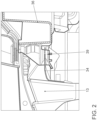
- FIG 2 is a detailed view of the connection area between the carrier 13 of the first module 12 and the carrier 36 of the second module 35 of the Figure 1 shown.
- the carrier 13 of the first module 12 has tabs 34 which engage in recesses 39 of the carrier 36 of the second module 35.
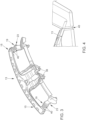
- FIG 3 a perspective view of the carrier 13 of the first module 12 of the cockpit 10 is shown.
- the projections 30 and the different areas can be clearly seen, namely the first area 15, the second area 19 and the third area 23 of the carrier 13.
- Material weakenings 40 are provided, which are used to form corresponding
- a corresponding material weakening 40 is also possible, for example, in Figure 4 which shows a perspective view of a portion of the support 13 of the first module 12.
Landscapes
- Engineering & Computer Science (AREA)
- Mechanical Engineering (AREA)
- Chemical & Material Sciences (AREA)
- Combustion & Propulsion (AREA)
- Transportation (AREA)
- Body Structure For Vehicles (AREA)
Description
- Die Erfindung betrifft ein Cockpit für ein Fahrzeug nach Anspruch 1.
- Grundsätzlich ist es aus dem Stand der Technik bekannt, ein Cockpit im Frontbereich eines Fahrzeuges einzusetzen, das bei einem Frontalaufprall Kräfte aufnehmen soll, um die Insassen zu schützen.
- So beschreibt beispielsweise
JP 2012-210 907 A - Die
EP 3 098 101 A1 zeigt ein Armaturenbrett eines Kraftfahrzeugs, das so angeordnet ist, dass es sich im Fall eines Aufpralls verformt. - Die
WO 2013/035042 A1 zeigt einen vorderen Fahrgastraum eines Fahrzeugs. Der vordere Fahrgastraum umfasst eine Steuerhalterung, die an einer Brandwand des Fahrzeugs montiert ist, um ein Fahrzeugsteuerpedal zu montieren, und eine Lenkungshalterung, die an einem Fahrzeugquerträger des Fahrzeugs montiert ist, um eine Lenksäule zu montieren. Eine Rückhaltehalterung mit vorbestimmter Form, die auf der Oberseite der Steuerhalterung mit einem vorbestimmten Abstand von einem unteren Ende der Lenkungshalterung montiert ist, um ein Eindringen der Feuerwand und der Steuerhalterung während eines Frontalaufpralls des Fahrzeugs zu verhindern. - Bei Fahrzeugen mit kurzem Vorderwagen und/oder nach vorne reichendem Cockpit wird dieses bei einem Frontalaufprall durch die intrudierende Frontalcrashbarriere beaufschlagt und somit relativ stark belastet. Das Cockpit kann bei einem Frontalaufprall unter ungünstigen Umständen zusammen mit dem Beifahrerairbag in den Fahrgastraum verschoben werden.
- Aufgabe der vorliegenden Erfindung ist es, ein Cockpit für ein Fahrzeug derart weiterzuentwickeln, dass die Verschiebung des Cockpits in den Fahrgastraum bei einem Frontalcrash verringert werden kann.
- Gelöst wird die vorgenannte Aufgabe durch ein Cockpit für ein Fahrzeug, das ein erstes Modul mit einem Träger und ein zweites Modul mit einem Träger umfasst, wobei der Träger des zweiten Moduls in einer ersten Richtung hinter dem Träger des ersten Moduls angeordnet ist. Ferner ist der Träger des zweiten Moduls höher als der Träger des ersten Moduls angeordnet. Durch die Anordnungen des Trägers des ersten Moduls, und somit vorzugsweise des gesamten ersten Moduls, schiebt sich dieses in einem Crashfall mit einer Krafteinwirkung auf das erste Modul in die erste Richtung zumindest teilweise unter den Träger des zweiten Moduls.
- Das Cockpit ist vorzugsweise in einem vorderen Bereich, insbesondere in einem Frontalbereich, des Fahrzeuges angeordnet. Insbesondere ist es unterhalb der Frontscheibe angeordnet. Bei einem Crashfall mit einer Krafteinwirkung auf das erste Modul in die erste Richtung handelt es sich somit um einen Frontalcrashfall. Ein Crashfall im Sinne der vorliegenden Patentanmeldung ist insbesondere als ein Frontalaufprall zu verstehen.
- In einem Crashfall schiebt sich der Träger des ersten Moduls zumindest teilweise unter den Träger des zweiten Moduls. Dadurch wird die Verschiebung des Cockpits in den Insassenraum reduziert. Gewährleistet wird die Verschiebung des Trägers des ersten Moduls, und zwar zumindest teilweise unter den Träger des zweiten Moduls, dadurch, dass der Träger des zweiten Moduls in einer ersten Richtung hinter dem Träger des ersten Moduls angeordnet ist und höher als der Träger des ersten Moduls. Die Tiefe bzw. Höhe wird vor allem in einer zweiten Richtung bestimmt, die senkrecht zur ersten Richtung steht. Die erste Richtung erstreckt sich insbesondere in einer Längsrichtung des Fahrzeuges, während die zweite Richtung der Höhenrichtung des Fahrzeuges entspricht. Unter dem Begriff "Höhe" ist daher vorzugsweise die Ausdehnung in Höhenrichtung des Fahrzeuges gemeint.
- Insbesondere sind der Träger des ersten Moduls und der Träger des zweiten Moduls in erster Richtung direkt hintereinander angeordnet. Insbesondere ist der Schwerpunkt des Trägers des zweiten Moduls höher angeordnet als der Schwerpunkt des Trägers des ersten Moduls. Ferner weist der Träger des ersten Moduls und der Träger des zweiten Moduls jeweils einen höchsten Punkt auf, wobei der höchste Punkt des Trägers des zweiten Moduls oberhalb des höchsten Punktes des Trägers des ersten Moduls liegt.
- Bei einem Crashfall mit einer Krafteinwirkung auf das erste Modul in die erste Richtung schiebt sich der Träger des ersten Moduls in Richtung des Trägers des zweiten Moduls. Mit anderen Worten wird die Frontalcrashbarriere in Richtung des zweiten Moduls verschoben. Dadurch, dass sich der Träger des ersten Moduls unter den Träger des zweiten Moduls schiebt, kann die Verschiebung des Cockpits in den Insassenraum reduziert und auch gegebenenfalls das Risiko eines Aufbrechens der Cockpitstruktur gesenkt werden.
- Erfindungsgemäß umschließt der Träger des zweiten Moduls zumindest teilweise einen Freiraum, wobei sich der Träger des ersten Moduls in dem Crashfall in den Freiraum schiebt. Dies trägt dazu bei, dass sich der Träger des ersten Moduls unter den Träger des zweiten Moduls schieben kann und somit die Verschiebung des gesamten Cockpits reduziert wird. Dabei ist der Träger des zweiten Moduls insbesondere derart ausgebildet, dass der Freiraum unterhalb des Trägers des zweiten Moduls angeordnet ist.
- Der Träger des ersten Moduls trägt hauptsächlich zu der Steifigkeit des ersten Moduls bei. Der Träger besteht insbesondere aus glasfaserverstärktem Kunststoff. Neben dem Träger kann das erste Modul noch weitere Module bzw. Bauteile aufweisen, die mit dem Träger über Verbindungen, beispielsweise Clipse oder Verschweißungen befestigt sind. Auch das zweite Modul kann einen Träger aufweisen sowie vorzugsweise weitere Elemente, beispielsweise einen Airbag. Ferner kann das Cockpit noch einen Modulquerträger aufweisen, der das zweite Modul des Cockpits aufnimmt.
- Insbesondere weist der Träger des ersten Moduls Sollknickstellen auf, sodass sich der Träger des ersten Moduls in dem Crashfall Z-förmig zusammenfaltet. Insbesondere faltet sich der Träger des ersten Moduls in dem Crashfall wie eine Ziehharmonika zusammen und reduziert somit maßgeblich die Verschiebung des Cockpits in den Insassenraum. Gewährleistet wird dies durch das Vorsehen von Sollknickstellen, damit sich das erste Modul vorhersehbar und kontrolliert deformiert. Das erste Modul dient somit hauptsächlich zur Aufnahme von Kräften in einem entsprechenden Crashfall und zum Abbau dieser durch Deformation. Dabei soll allerdings sichergestellt werden, dass sich das Cockpit insgesamt so wenig wie möglich in den Insassenraum verschiebt. Die Z-Faltung des ersten Moduls erstreckt sich insbesondere zumindest grob in erster Richtung. Insbesondere weist der Träger des ersten Moduls mindestens drei, vorzugsweise genau drei, Bereiche auf, wobei zwischen jeweils benachbarten Bereichen eine Sollknickstelle ausgebildet ist. Der Träger ist vor allem einstückig ausgebildet.
- Die Sollknickstellen können durch eine geometrische Ausbildung des Trägers und/oder durch lokale Materialschwächung ausgebildet sein. Unter dem Begriff "geometrische Ausbildung" ist insbesondere zu verstehen, dass der Träger bereits vor dem Crashfall, d.h. in vorgefertigter Form, eine abgewinkelte Ausbildung aufweist, die dafür sorgt, dass sich der Träger an den bereits abgewinkelten Bereichen entsprechend faltet. Somit kann eine Z-Faltung durch die Geometrie des ersten Moduls zumindest angedeutet sein und sichergestellt werden, dass sich das erste Modul bei einem Aufprall mit einer Krafteinwirkung auf das erste Modul 12 in die erste Richtung 11 entsprechend "weiter" faltet.
- Ferner kann eine verringerte Höhe des Trägers in zweiter Richtung eine geometrische Ausbildung darstellen und somit eine Sollknickstelle ausmachen.
- Es können lokale Materialschwächungen ausgebildet sein, die dafür sorgen, dass sich das erste Modul an den entsprechenden Stellen faltet.
- Insbesondere weist der Träger des ersten Moduls einen ersten Bereich auf, wobei der erste Bereich in einem Längsschnitt des Cockpits in erster Richtung und zweiter Richtung in einem Winkel zwischen 5° und 15°, vorzugsweise zwischen 7,5° und 12,5°, insbesondere in einem Winkel von etwa 10°, zur ersten Richtung steht.
- Ferner kann der Träger des ersten Moduls einen zweiten Bereich aufweisen, der gegenüber dem ersten Bereich abgewinkelt ist. Insbesondere schließt der zweite Bereich einen Winkel mit der ersten Richtung ein, der zwischen 100° und 150°, insbesondere zwischen 120° und 130°, insbesondere etwa 125°, beträgt. Der erste Bereich und der zweite Bereich umschießen somit einen Winkel zueinander, der vorzugsweise zwischen 90° und 130°, insbesondere zwischen 110° und 120°, beträgt.
- Ferner bevorzugt weist der Träger des ersten Moduls einen dritten Bereich auf, wobei der dritte Bereich einen Winkel mit der ersten Richtung einschließt, der zwischen 10° und 40°, insbesondere zwischen 20° und 30°, am meisten bevorzugt etwa 25°, beträgt. Der dritte Bereich und der zweite Bereich schließen somit zueinander einen Winkel zwischen 90° und 110°, insbesondere zwischen 95° und 105°, ein. Durch die abgewinkelte Ausbildung des Trägers des ersten Moduls werden Sollknickstellen zwischen den verschiedenen Bereichen gebildet.
- Insbesondere sind das erste Modul und das zweite Modul durch das Eingreifen von Laschen des ersten Moduls und Ausnehmungen des zweiten Moduls miteinander verbunden. Bei den Laschen handelt es sich insbesondere um Blechlaschen. Sie sind insbesondere am Träger des ersten Moduls angeordnet. Die Laschen greifen in Ausnehmungen des zweiten Moduls, die vor allem am Träger des zweiten Moduls angeordnet sind. Das erste Modul und das zweite Modul sind somit durch Absteckung miteinander verbunden. Das zweite Modul fungiert als Gegenlager gegenüber dem ersten Modul bei einem Zusammenschieben des ersten Moduls. Durch die Anbindung des ersten Moduls an das zweite Modul wird das erste Modul in den Freiraum unter dem zweiten Modul gezogen.
- Im ersten und/oder dritten Bereich kann der Träger des ersten Moduls ferner Auskragungen nach unten aufweisen. Die Auskragungen dienen als Luftführungskanäle.
- Der Träger des ersten Moduls, insbesondere dessen erster Bereich, zweiter Bereich und dritter Bereich, umschließen bis auf die Auskragungen im ersten und dritten Bereich einen Höhenbereich. Der Träger des zweiten Moduls ist ebenfalls in diesem gesamten Höhenbereich angeordnet, wobei sich der Träger des zweiten Moduls aus dem Höhenbereich nach oben heraus erstreckt und somit insgesamt höher angeordnet ist, sodass das zweite Modul bzw. dessen Träger als Gegenlager agieren kann und sich somit der Träger des ersten Moduls auf der einen Seite Z-förmig zusammenklappen kann und auf der anderen Seite in den Freiraum unterhalb des Trägers des zweiten Moduls schieben kann.
- Die Laschen zur Befestigung des ersten Moduls an dem zweiten Modul erstrecken sich insbesondere in erster Richtung, wobei sich der Träger des ersten Moduls in dem Crashfall derart zusammenfaltet, dass die Laschen aus den Ausnehmungen gezogen werden und sich die Verbindung zwischen dem ersten Modul und dem zweiten Modul löst. Gelöst wird die Verbindung insbesondere dadurch, dass durch die Zusammenfaltung die Laschen aus den Ausnehmungen gezogen werden.
- Insbesondere weist der erste Bereich ein erstes Ende und ein zweites Ende auf, wobei er am zweiten Ende in den zweiten Bereich übergeht. Ferner weist der zweite Bereich ein erstes Ende und ein zweites Ende auf, wobei er an dem ersten Ende in den ersten Bereich und an seinem zweiten Ende in den dritten Bereich übergeht. Dabei faltet sich der Träger des ersten Moduls derart zusammen, dass sich das zweite Ende des ersten Bereichs aufstellt. Ferner wird auch das erste Ende des dritten Bereichs nach unten gedrückt, sodass sich dadurch die Laschen aus den Ausnehmungen ziehen. Insbesondere schiebt sich das erste Ende des dritten Bereichs beziehungsweise das zweite Ende des zweiten Bereichs in Richtung des ersten Endes des ersten Bereichs.
- Ferner bezieht sich die Erfindung auch auf ein Fahrzeug umfassend ein oben beschriebenes Cockpit, wobei das Fahrzeug einen Frontalbereich aufweist, in dem das Cockpit angeordnet ist.
- Es zeigen schematisch:
- Figur 1
- eine Schnittdarstellung eines erfindungsgemäßen Cockpits entlang der ersten Richtung sowie der Höhenrichtung eines Fahrzeuges;
- Figur 2
- eine detaillierte Ansicht des Verbindungsbereichs zwischen dem Träger des ersten Moduls und dem Träger des zweiten Moduls der
Figur 1 ; - Figur 3
- eine perspektivische Ansicht des Trägers des ersten Moduls des Cockpits der
Figur 1 ; - Figur 4
- eine perspektivische Ansicht auf einen Bereich des Trägers des ersten Moduls; und
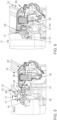
- Figuren 5 und 6
- eine Faltung des Trägers des ersten Moduls des Cockpits der
Figur 1 in einem Crashfall mit einer Krafteinwirkung auf das erste Modul in die erste Richtung. -
Figur 1 zeigt eine Schnittdarstellung eines erfindungsgemäßen Cockpits 10 entlang der ersten Richtung 11 sowie der Höhenrichtung eines Fahrzeuges. - Das Cockpit 10 weist ein erstes Modul 12 und ein zweites Modul 35 auf. Das erste Modul 12 umfasst einen Träger 13. Zudem weist das zweite Modul 35 einen Träger 36 auf. Ferner umfasst das erste Modul 12 ein Oberteil 14.
- Der Träger 13 ist bereits abgewinkelt vorgeformt, sodass er sich bei einem Crashfall mit einer Krafteinwirkung auf das erste Modul 12 in die erste Richtung 11 Z-förmig zusammenfaltet. Der Träger 13 weist einen ersten Bereich 15 mit einem ersten Ende 16, das der ersten Richtung 11 zugewandt ist, und einem zweiten Ende 17 auf. Ferner weist der Träger 13 einen zweiten Bereich 19 mit einem ersten Ende 20 und einem zweiten Ende 21 auf und einen dritten Bereich 23 mit einem ersten Ende 24 und einem zweiten Ende 25.
- Zwischen den entsprechenden Bereichen sind Sollknickstellen 29 ausgebildet. Diese sind durch eine geometrische Ausbildung des Trägers 13 ausgebildet. Und zwar schließt der erste Bereich 15 einen ersten Winkel 18 mit der ersten Richtung 11 ein, während der zweite Bereich 19 einen zweiten Winkel 22 mit der ersten Richtung 11 einschließt. Der dritte Bereich 23 schließt einen dritten Winkel 26 mit der ersten Richtung 11 ein. Ferner schließt der erste Bereich 15 mit dem zweiten Bereich 19 einen viertel Winkel 27 und der zweite Bereich 19 mit dem dritten Bereich 23 einen fünften Winkel 28 ein.
- Der erste Bereich 15 des Trägers 13 weist Auskragungen 30 auf, die in
Figur 1 nach unten ragen. Gleiches gilt für den dritten Bereich 23, der ebenfalls entsprechende Auskragungen 30 aufweist. Bis auf die Auskragungen 30 schließt der Träger 13 des ersten Moduls 12 einen Höhenbereich 31 mit einem oberen Ende 32 und einem unteren Ende 33 ein. Der Träger 36 des zweiten Moduls 35 ist mindestens auf der gesamten Höhe des Höhenbereichs 31 angeordnet und ragt über das obere Ende 32 des Höhenbereichs 31 hervor, sodass er insgesamt höher angeordnet ist als der Träger 13 des ersten Moduls 12. - Ferner kann das zweite Modul 35 einen Airbag 37 und einen Querträger 38 umfassen.
- In
Figur 2 ist eine detaillierte Ansicht des Verbindungsbereichs zwischen dem Träger 13 des ersten Moduls 12 und dem Träger 36 des zweiten Moduls 35 derFigur 1 gezeigt. Der Träger 13 des ersten Moduls 12 weist Laschen 34 auf, die in Ausnehmungen 39 des Trägers 36 des zweiten Moduls 35 greifen. - In
Figur 3 ist eine perspektivische Ansicht des Trägers 13 des ersten Moduls 12 des Cockpits 10 gezeigt. Deutlich sind die Auskragungen 30 sowie die unterschiedlichen Bereiche zu sehen, und zwar der erste Bereich 15, der zweite Bereich 19 und der dritte Bereich 23 des Trägers 13. Dabei sind Materialschwächungen 40 vorgesehen, die zur Ausbildung entsprechender Sollknickstellen beitragen. Eine entsprechende Materialschwächung 40 ist beispielsweise auch inFigur 4 zu sehen, die eine perspektivische Ansicht auf einen Bereich des Trägers 13 des ersten Moduls 12 zeigt. - In den
Figuren 5 und 6 ist gezeigt, wie sich der Träger 13 des ersten Moduls 12 des Cockpits 10 in einem Crashfall mit einer Krafteinwirkung auf das erste Modul 12 in die erste Richtung 11 zusammenfaltet. Und zwar ist dort zu sehen, wie sich das zweite Ende 17 des ersten Bereiches 15 nach oben schiebt, während sich, wie inFigur 6 zu sehen ist, das erste Ende 24 des dritten Bereichs 23 nach unten schiebt. Ferner schiebt sich das erste Ende 24 des dritten Bereichs 23 beziehungsweise das zweite Ende 21 des zweiten Bereichs 19 in Richtung des ersten Endes 16 des ersten Bereichs 15. Nach der Z-Faltung des ersten Moduls 12 an das zweite Modul 35, das als Gegenlager fungiert, wird das erste Modul 12 in den Freiraum 41 unter dem zweiten Modul 35 gezogen. -
- 10
- Cockpit
- 11
- erste Richtung
- 12
- erstes Modul
- 13
- Träger
- 14
- Oberteil
- 15
- erster Bereich
- 16
- erstes Ende des ersten Bereichs
- 17
- zweites Ende des ersten Bereichs
- 18
- erster Winkel
- 19
- zweiter Bereich
- 20
- erstes Ende des zweiten Bereichs
- 21
- zweites Ende des zweiten Bereichs
- 22
- zweiter Winkel
- 23
- dritter Bereich
- 24
- erstes Ende des dritten Bereichs
- 25
- zweites Ende des dritten Bereichs
- 26
- dritter Winkel
- 27
- vierter Winkel
- 28
- fünfter Winkel
- 29
- Sollknickstelle
- 30
- Auskragung
- 31
- Höhenbereich
- 32
- oberes Ende des Höhenbereichs
- 33
- unteres Ende des Höhenbereichs
- 34
- Laschen
- 35
- zweites Modul
- 36
- Träger
- 37
- Airbag
- 38
- Querträger
- 39
- Ausnehmungen
- 40
- Materialschwächung
- 41
- Freiraum
Claims (8)
- Cockpit (10) für ein Fahrzeug,wobei das Cockpit (10) ein erstes Modul (12) mit einem Träger (13) und ein zweites Modul (35) mit einem Träger (36) umfasst,wobei der Träger (36) des zweiten Moduls (35) in einer ersten Richtung (11) hinter dem Träger (13) des ersten Moduls (12) und höher als der Träger (13) des ersten Moduls (12) angeordnet ist,sodass sich in einem Crashfall mit einer Krafteinwirkung auf das erste Modul (12) in die erste Richtung (11) der Träger (13) des ersten Moduls (12) zumindest teilweise unter den Träger (36) des zweiten Moduls (35) schiebt,dadurch gekennzeichnet, dassder Träger (36) des zweiten Moduls (35) zumindest teilweise einen Freiraum (41) umschließt,wobei sich der Träger (13) des ersten Moduls (12) in dem Crashfall in den Freiraum (41) schiebt, sodass sich der Träger (13) des ersten Moduls (12) unter den Träger (36) des zweiten Moduls (35) schieben kann.
- Cockpit (10) nach Anspruch 1,
dadurch gekennzeichnet, dass
der Träger (13) des ersten Moduls (12) Sollknickstellen (29) aufweist, sodass sich der Träger (13) des ersten Moduls (12) in dem Crashfall Z-förmig zusammenfaltet. - Cockpit (10) nach Anspruch 2,
dadurch gekennzeichnet, dass
der Träger (13) des ersten Moduls (12) mindestens drei Bereiche aufweist, wobei zwischen jeweils benachbarten Bereichen eine Sollknickstelle (29) ausgebildet ist. - Cockpit (10) nach einem der Ansprüche 2 oder 3,
dadurch gekennzeichnet, dass
die Sollknickstellen (29) durch eine geometrische Ausbildung des Trägers (13) und/oder durch lokale Materialschwächungen (40) ausgebildet sind. - Cockpit (10) nach Anspruch 4,
dadurch gekennzeichnet, dassdie geometrische Ausbildung eine abgewinkelte Ausbildung des Trägers (13) und/oderund/oder eine verringerte Höhe des Trägers (13) ist. - Cockpit (10) nach einem der vorherigen Ansprüche,
dadurch gekennzeichnet, dass
das erste Modul (12) und das zweite Modul (35) durch das Eingreifen von Laschen (34) des ersten Moduls und Ausnehmungen (39) des zweiten Moduls (35) miteinander verbunden sind. - Cockpit (10) nach Anspruch 6,
dadurch gekennzeichnet, dasssich die Laschen (34) in erster Richtung (11) erstrecken,wobei sich der Träger (13) des ersten Moduls (12) in einem Crashfall mit einer Krafteinwirkung auf das erste Modul (12) in die erste Richtung (11) derart zusammenfaltet, dass die Laschen (34) aus den Ausnehmungen (39) gezogen werden und sich die Verbindung zwischen dem ersten Modul (12) und dem zweiten Modul (35) löst. - Fahrzeug, umfassend ein Cockpit (10) nach einem der vorherigen Ansprüche.
Applications Claiming Priority (2)
| Application Number | Priority Date | Filing Date | Title |
|---|---|---|---|
| DE102020200805.1A DE102020200805A1 (de) | 2020-01-23 | 2020-01-23 | Cockpit für ein Fahrzeug |
| PCT/EP2021/050958 WO2021148355A1 (de) | 2020-01-23 | 2021-01-18 | Cockpit für ein fahrzeug |
Publications (2)
| Publication Number | Publication Date |
|---|---|
| EP4090577A1 EP4090577A1 (de) | 2022-11-23 |
| EP4090577B1 true EP4090577B1 (de) | 2024-07-17 |
Family
ID=74205832
Family Applications (1)
| Application Number | Title | Priority Date | Filing Date |
|---|---|---|---|
| EP21701263.2A Active EP4090577B1 (de) | 2020-01-23 | 2021-01-18 | Cockpit für ein fahrzeug |
Country Status (5)
| Country | Link |
|---|---|
| US (1) | US11952041B2 (de) |
| EP (1) | EP4090577B1 (de) |
| CN (1) | CN114929565B (de) |
| DE (1) | DE102020200805A1 (de) |
| WO (1) | WO2021148355A1 (de) |
Families Citing this family (1)
| Publication number | Priority date | Publication date | Assignee | Title |
|---|---|---|---|---|
| DE102020200805A1 (de) * | 2020-01-23 | 2021-07-29 | Volkswagen Aktiengesellschaft | Cockpit für ein Fahrzeug |
Family Cites Families (41)
| Publication number | Priority date | Publication date | Assignee | Title |
|---|---|---|---|---|
| DE2148108A1 (de) * | 1971-09-27 | 1973-04-05 | Opel Adam Ag | Tragwerk fuer karosserien bzw. aufbauten von fahrzeugen, insbesondere personenkraftfahrzeugen |
| FR2661883B1 (fr) * | 1990-05-11 | 1992-07-17 | Renault | Structure plastique de separation entre l'habitacle et le compartiment moteur d'un vehicule automobile. |
| US5372216A (en) * | 1990-10-08 | 1994-12-13 | Mazda Motor Corporation | Power plant supporting structure of automotive vehicle |
| US5564769A (en) * | 1994-12-19 | 1996-10-15 | Chrysler Corporations | Reinforced instrument panel assembly |
| DE19753178A1 (de) * | 1997-11-20 | 1999-06-10 | Sommer Allibert Lignotock Gmbh | Cockpit für Kraftfahrzeuge |
| FR2834262B1 (fr) | 2001-12-31 | 2004-04-02 | Renault | Habitacle de vehicule automobile, equipe de moyens de protection contre des chocs |
| JP3992507B2 (ja) * | 2002-02-07 | 2007-10-17 | ダイハツ工業株式会社 | 自動車のステアリング装置における衝撃力緩和構造 |
| FR2841506B1 (fr) * | 2002-06-26 | 2004-08-27 | Faurecia Interieur Ind | Ensemble de planche de bord et vehicule comprenant l'ensemble |
| US7509191B2 (en) * | 2003-09-12 | 2009-03-24 | Honda Motor Co., Ltd. | Frame deformation control apparatus |
| JP4779471B2 (ja) * | 2004-10-27 | 2011-09-28 | 日産自動車株式会社 | 車両の前部構造 |
| DE102004063741A1 (de) * | 2004-12-29 | 2006-10-26 | Volkswagen Ag | Vorderwagen für ein Fahrzeug, insbesondere für ein Kraftfahrzeug |
| DE102006018282A1 (de) | 2006-04-20 | 2007-10-31 | Daimlerchrysler Ag | Energieabsorbierendes Deformationsprofil |
| JP4304537B2 (ja) * | 2007-02-23 | 2009-07-29 | トヨタ自動車株式会社 | 車両骨格構造 |
| AT505870A1 (de) * | 2007-09-20 | 2009-04-15 | Siemens Transportation Systems | Crash-modul fur ein schienenfahrzeug |
| JP5029328B2 (ja) * | 2007-12-05 | 2012-09-19 | マツダ株式会社 | 自動車の前部車体構造 |
| US7762619B2 (en) * | 2008-07-29 | 2010-07-27 | Ford Global Technologies, Llc | Sequential crash hinges in automotive frame rails |
| DE102008039315A1 (de) * | 2008-08-22 | 2010-02-25 | Volkswagen Ag | Crashoptimiertes Frontendmodul |
| DE102008052007A1 (de) | 2008-10-10 | 2010-04-15 | Dr. Ing. H.C. F. Porsche Aktiengesellschaft | Cockpitquerträger für ein Kraftfahrzeug |
| JP5246139B2 (ja) * | 2009-02-26 | 2013-07-24 | トヨタ自動車株式会社 | 車両の前部構造 |
| FR2946948B1 (fr) * | 2009-06-19 | 2015-09-04 | Faurecia Interieur Ind | Planche de bord de vehicule automobile agencee pour se deformer en cas de choc |
| JP5504820B2 (ja) * | 2009-10-26 | 2014-05-28 | マツダ株式会社 | 車両の前部車体構造 |
| US8562068B2 (en) * | 2010-03-02 | 2013-10-22 | Toyota Jidosha Kabushiki Kaisha | Vehicle framework member |
| CN103153764A (zh) * | 2010-10-04 | 2013-06-12 | 沃尔沃拉斯特瓦格纳公司 | 包括变形结构的车辆 |
| DE102011009605B4 (de) * | 2011-01-27 | 2014-11-27 | Audi Ag | Anordnung einer Instrumententafel im Innenraum eines Kraftfahrzeuges |
| JP2012210907A (ja) | 2011-03-31 | 2012-11-01 | Kojima Press Industry Co Ltd | 車両の衝撃吸収構造 |
| DE102011100687A1 (de) | 2011-05-06 | 2012-11-08 | GM Global Technology Operations LLC (n. d. Gesetzen des Staates Delaware) | Instrumententafelanordnung |
| WO2013018401A1 (ja) * | 2011-07-30 | 2013-02-07 | 本田技研工業株式会社 | 車体前部構造 |
| WO2013035042A1 (en) * | 2011-09-07 | 2013-03-14 | Tata Motors Limited | A front passenger compartment of a vehicle |
| CN103796905A (zh) * | 2011-10-25 | 2014-05-14 | 丰田自动车株式会社 | 骨架构件 |
| WO2013150806A1 (ja) * | 2012-04-05 | 2013-10-10 | 本田技研工業株式会社 | 車体前部構造 |
| KR101519741B1 (ko) * | 2013-11-25 | 2015-05-12 | 현대자동차주식회사 | 자동차의 칵핏 모듈용 가이드 마운팅 브라켓 |
| DE102014222441A1 (de) * | 2014-11-04 | 2016-05-04 | Bayerische Motoren Werke Aktiengesellschaft | Kraftfahrzeug und Verfahren zur Herstellung eines Kraftfahrzeugs |
| GB2540541B (en) | 2015-07-20 | 2019-04-10 | Ford Global Tech Llc | A motor vehicle having an instrument panel |
| JP6264349B2 (ja) * | 2015-09-16 | 2018-01-24 | トヨタ自動車株式会社 | 車両前部構造 |
| CN106090799A (zh) | 2016-06-28 | 2016-11-09 | 苏州朗米尔照明科技有限公司 | 一种多功能智能路灯 |
| DE102016010612B4 (de) * | 2016-09-01 | 2020-10-22 | Audi Ag | Cockpitmodul mit Scheibenquerträger und Kraftfahrzeug mit einem solchen Cockpitmodul |
| GB2569582B (en) * | 2017-12-20 | 2020-06-17 | Ford Global Tech Llc | A powertrain support mount assembly |
| DE102019204789B4 (de) * | 2019-04-04 | 2021-11-04 | Audi Ag | Deformationsvorrichtung für ein Kraftfahrzeug und Kraftfahrzeug mit einer Deformationsvorrichtung |
| DE102020200805A1 (de) * | 2020-01-23 | 2021-07-29 | Volkswagen Aktiengesellschaft | Cockpit für ein Fahrzeug |
| US11603134B2 (en) * | 2020-10-08 | 2023-03-14 | GM Global Technology Operations LLC | Energy attenuating longitudinal frame member for a vehicle including asymmetric crash response |
| DE102021121942B4 (de) * | 2021-08-24 | 2024-08-08 | Dr. Ing. H.C. F. Porsche Aktiengesellschaft | Batterieelektrisches Fahrzeug |
-
2020
- 2020-01-23 DE DE102020200805.1A patent/DE102020200805A1/de active Pending
-
2021
- 2021-01-18 WO PCT/EP2021/050958 patent/WO2021148355A1/de not_active Ceased
- 2021-01-18 CN CN202180010236.1A patent/CN114929565B/zh active Active
- 2021-01-18 EP EP21701263.2A patent/EP4090577B1/de active Active
-
2022
- 2022-07-25 US US17/872,685 patent/US11952041B2/en active Active
Also Published As
| Publication number | Publication date |
|---|---|
| US20220355866A1 (en) | 2022-11-10 |
| WO2021148355A1 (de) | 2021-07-29 |
| EP4090577A1 (de) | 2022-11-23 |
| CN114929565B (zh) | 2024-07-02 |
| CN114929565A (zh) | 2022-08-19 |
| DE102020200805A1 (de) | 2021-07-29 |
| US11952041B2 (en) | 2024-04-09 |
Similar Documents
| Publication | Publication Date | Title |
|---|---|---|
| EP3668777B1 (de) | Fahrzeuglängsträgeranordnung | |
| DE102010039109B4 (de) | Kraftfahrzeug | |
| DE102017211160B4 (de) | Karosseriestruktur für ein Fahrzeug | |
| DE19830303B4 (de) | Anordnung eines Instrumententafelträgers in einer Fahrzeugkarosserie und Instrumententafelträger | |
| WO2007085314A1 (de) | Energieabsorptionskörper, vorrichtung zum schutz gegen einen aufprall, kraftfahrzeug-innenverkleidungsteil und querträger | |
| DE102018100701A1 (de) | Dachrahmen mit einer Strebe zum Verstärken gewölbter Elemente | |
| EP1738943A2 (de) | Türstruktur eines Kraftfahrzeuges | |
| DE102007026951A1 (de) | Sitzträgeranordnung und Aufbau für einen Omnibus | |
| DE102013002421B4 (de) | B-Säule, für ein Kraftfahrzeug | |
| EP4228951B1 (de) | Bodenstruktur für einen personenkraftwagen und baukastensystem für eine karosserie eines kraftwagens | |
| EP1234751B1 (de) | Karosserievorderbau eines Kraftfahrzeuges | |
| DE102004050435A1 (de) | Stoßfängersystem für Kraftfahrzeug | |
| EP3668776B1 (de) | Vorbaustrukturanordnung für einen kraftwagenrohbau sowie aggregateträger für eine derartige vorbaustrukturanordnung | |
| DE102007014391B4 (de) | Seitenaufprallschutzeinrichtung, die zwischen Innen- und Außenbleche eingebaut ist | |
| DE3245741C2 (de) | Lenkung für Kraftwagen | |
| EP2756990B1 (de) | Frontscheinwerfer | |
| EP4090577A1 (de) | Cockpit für ein fahrzeug | |
| DE10028704A1 (de) | Kraftfahrzeug mit Aggregateabsenkung | |
| DE4304920B4 (de) | Vorderwagen für ein Kraftfahrzeug | |
| WO2014202190A1 (de) | FUßGÄNGER- UND FAHRRADFAHRER-SCHUTZEINRICHTUNG FÜR EIN KRAFTFAHRZEUG UND GASSACK ZUR VERWENDUNG IN EINER SOLCHEN FUßGÄNGER- UND FAHRRADFAHRER-SCHUTZEINRICHTUNG | |
| DE102006040032A1 (de) | Fahrzeug mit einer gegen einen Seitenaufprall ausgelegten Instrumententafel | |
| DE202015001448U1 (de) | Fahrzeugsäule, insbesondere A-Säule für ein Kraftfahrzeug | |
| DE10309958A1 (de) | Kraftfahrzeug mit einer Fußgängerschutzeinrichtung sowie Verfahren zum Betreiben einer Fußgängerschutzeinrichtung an einem solchen Kraftfahrzeug | |
| DE102006008222B4 (de) | Kraftfahrzeug mit einer Vorrichtung zur Abdeckung eines Kofferraums | |
| DE102012013692A1 (de) | Stoßfängeranordnung für einen Personenkraftwagen |
Legal Events
| Date | Code | Title | Description |
|---|---|---|---|
| STAA | Information on the status of an ep patent application or granted ep patent |
Free format text: STATUS: UNKNOWN |
|
| STAA | Information on the status of an ep patent application or granted ep patent |
Free format text: STATUS: THE INTERNATIONAL PUBLICATION HAS BEEN MADE |
|
| PUAI | Public reference made under article 153(3) epc to a published international application that has entered the european phase |
Free format text: ORIGINAL CODE: 0009012 |
|
| STAA | Information on the status of an ep patent application or granted ep patent |
Free format text: STATUS: REQUEST FOR EXAMINATION WAS MADE |
|
| 17P | Request for examination filed |
Effective date: 20220819 |
|
| AK | Designated contracting states |
Kind code of ref document: A1 Designated state(s): AL AT BE BG CH CY CZ DE DK EE ES FI FR GB GR HR HU IE IS IT LI LT LU LV MC MK MT NL NO PL PT RO RS SE SI SK SM TR |
|
| RAV | Requested validation state of the european patent: fee paid |
Extension state: TN Effective date: 20221024 Extension state: MD Effective date: 20221024 Extension state: MA Effective date: 20221024 Extension state: KH Effective date: 20221024 |
|
| RAX | Requested extension states of the european patent have changed |
Extension state: ME Payment date: 20221024 Extension state: BA Payment date: 20221024 |
|
| GRAP | Despatch of communication of intention to grant a patent |
Free format text: ORIGINAL CODE: EPIDOSNIGR1 |
|
| STAA | Information on the status of an ep patent application or granted ep patent |
Free format text: STATUS: GRANT OF PATENT IS INTENDED |
|
| RIC1 | Information provided on ipc code assigned before grant |
Ipc: B60K 37/10 20240101ALI20240314BHEP Ipc: B60K 35/00 20060101ALI20240314BHEP Ipc: B60K 37/00 20060101ALI20240314BHEP Ipc: B60R 21/045 20060101ALI20240314BHEP Ipc: B62D 21/15 20060101ALI20240314BHEP Ipc: B62D 25/14 20060101AFI20240314BHEP |
|
| INTG | Intention to grant announced |
Effective date: 20240328 |
|
| P01 | Opt-out of the competence of the unified patent court (upc) registered |
Effective date: 20240502 |
|
| GRAS | Grant fee paid |
Free format text: ORIGINAL CODE: EPIDOSNIGR3 |
|
| GRAA | (expected) grant |
Free format text: ORIGINAL CODE: 0009210 |
|
| STAA | Information on the status of an ep patent application or granted ep patent |
Free format text: STATUS: THE PATENT HAS BEEN GRANTED |
|
| AK | Designated contracting states |
Kind code of ref document: B1 Designated state(s): AL AT BE BG CH CY CZ DE DK EE ES FI FR GB GR HR HU IE IS IT LI LT LU LV MC MK MT NL NO PL PT RO RS SE SI SK SM TR |
|
| REG | Reference to a national code |
Ref country code: CH Ref legal event code: EP |
|
| REG | Reference to a national code |
Ref country code: DE Ref legal event code: R096 Ref document number: 502021004395 Country of ref document: DE |
|
| REG | Reference to a national code |
Ref country code: IE Ref legal event code: FG4D Free format text: LANGUAGE OF EP DOCUMENT: GERMAN |
|
| REG | Reference to a national code |
Ref country code: LT Ref legal event code: MG9D |
|
| REG | Reference to a national code |
Ref country code: NL Ref legal event code: MP Effective date: 20240717 |
|
| PG25 | Lapsed in a contracting state [announced via postgrant information from national office to epo] |
Ref country code: PT Free format text: LAPSE BECAUSE OF FAILURE TO SUBMIT A TRANSLATION OF THE DESCRIPTION OR TO PAY THE FEE WITHIN THE PRESCRIBED TIME-LIMIT Effective date: 20241118 |
|
| PG25 | Lapsed in a contracting state [announced via postgrant information from national office to epo] |
Ref country code: NL Free format text: LAPSE BECAUSE OF FAILURE TO SUBMIT A TRANSLATION OF THE DESCRIPTION OR TO PAY THE FEE WITHIN THE PRESCRIBED TIME-LIMIT Effective date: 20240717 |
|
| PG25 | Lapsed in a contracting state [announced via postgrant information from national office to epo] |
Ref country code: PT Free format text: LAPSE BECAUSE OF FAILURE TO SUBMIT A TRANSLATION OF THE DESCRIPTION OR TO PAY THE FEE WITHIN THE PRESCRIBED TIME-LIMIT Effective date: 20241118 Ref country code: NL Free format text: LAPSE BECAUSE OF FAILURE TO SUBMIT A TRANSLATION OF THE DESCRIPTION OR TO PAY THE FEE WITHIN THE PRESCRIBED TIME-LIMIT Effective date: 20240717 |
|
| PG25 | Lapsed in a contracting state [announced via postgrant information from national office to epo] |
Ref country code: NO Free format text: LAPSE BECAUSE OF FAILURE TO SUBMIT A TRANSLATION OF THE DESCRIPTION OR TO PAY THE FEE WITHIN THE PRESCRIBED TIME-LIMIT Effective date: 20241017 |
|
| PG25 | Lapsed in a contracting state [announced via postgrant information from national office to epo] |
Ref country code: PL Free format text: LAPSE BECAUSE OF FAILURE TO SUBMIT A TRANSLATION OF THE DESCRIPTION OR TO PAY THE FEE WITHIN THE PRESCRIBED TIME-LIMIT Effective date: 20240717 Ref country code: GR Free format text: LAPSE BECAUSE OF FAILURE TO SUBMIT A TRANSLATION OF THE DESCRIPTION OR TO PAY THE FEE WITHIN THE PRESCRIBED TIME-LIMIT Effective date: 20241018 Ref country code: FI Free format text: LAPSE BECAUSE OF FAILURE TO SUBMIT A TRANSLATION OF THE DESCRIPTION OR TO PAY THE FEE WITHIN THE PRESCRIBED TIME-LIMIT Effective date: 20240717 |
|
| PG25 | Lapsed in a contracting state [announced via postgrant information from national office to epo] |
Ref country code: BG Free format text: LAPSE BECAUSE OF FAILURE TO SUBMIT A TRANSLATION OF THE DESCRIPTION OR TO PAY THE FEE WITHIN THE PRESCRIBED TIME-LIMIT Effective date: 20240717 |
|
| PG25 | Lapsed in a contracting state [announced via postgrant information from national office to epo] |
Ref country code: LV Free format text: LAPSE BECAUSE OF FAILURE TO SUBMIT A TRANSLATION OF THE DESCRIPTION OR TO PAY THE FEE WITHIN THE PRESCRIBED TIME-LIMIT Effective date: 20240717 |
|
| PG25 | Lapsed in a contracting state [announced via postgrant information from national office to epo] |
Ref country code: IS Free format text: LAPSE BECAUSE OF FAILURE TO SUBMIT A TRANSLATION OF THE DESCRIPTION OR TO PAY THE FEE WITHIN THE PRESCRIBED TIME-LIMIT Effective date: 20241117 |
|
| PG25 | Lapsed in a contracting state [announced via postgrant information from national office to epo] |
Ref country code: HR Free format text: LAPSE BECAUSE OF FAILURE TO SUBMIT A TRANSLATION OF THE DESCRIPTION OR TO PAY THE FEE WITHIN THE PRESCRIBED TIME-LIMIT Effective date: 20240717 |
|
| PG25 | Lapsed in a contracting state [announced via postgrant information from national office to epo] |
Ref country code: ES Free format text: LAPSE BECAUSE OF FAILURE TO SUBMIT A TRANSLATION OF THE DESCRIPTION OR TO PAY THE FEE WITHIN THE PRESCRIBED TIME-LIMIT Effective date: 20240717 Ref country code: RS Free format text: LAPSE BECAUSE OF FAILURE TO SUBMIT A TRANSLATION OF THE DESCRIPTION OR TO PAY THE FEE WITHIN THE PRESCRIBED TIME-LIMIT Effective date: 20241017 |
|
| PG25 | Lapsed in a contracting state [announced via postgrant information from national office to epo] |
Ref country code: RS Free format text: LAPSE BECAUSE OF FAILURE TO SUBMIT A TRANSLATION OF THE DESCRIPTION OR TO PAY THE FEE WITHIN THE PRESCRIBED TIME-LIMIT Effective date: 20241017 Ref country code: PL Free format text: LAPSE BECAUSE OF FAILURE TO SUBMIT A TRANSLATION OF THE DESCRIPTION OR TO PAY THE FEE WITHIN THE PRESCRIBED TIME-LIMIT Effective date: 20240717 Ref country code: NO Free format text: LAPSE BECAUSE OF FAILURE TO SUBMIT A TRANSLATION OF THE DESCRIPTION OR TO PAY THE FEE WITHIN THE PRESCRIBED TIME-LIMIT Effective date: 20241017 Ref country code: LV Free format text: LAPSE BECAUSE OF FAILURE TO SUBMIT A TRANSLATION OF THE DESCRIPTION OR TO PAY THE FEE WITHIN THE PRESCRIBED TIME-LIMIT Effective date: 20240717 Ref country code: IS Free format text: LAPSE BECAUSE OF FAILURE TO SUBMIT A TRANSLATION OF THE DESCRIPTION OR TO PAY THE FEE WITHIN THE PRESCRIBED TIME-LIMIT Effective date: 20241117 Ref country code: HR Free format text: LAPSE BECAUSE OF FAILURE TO SUBMIT A TRANSLATION OF THE DESCRIPTION OR TO PAY THE FEE WITHIN THE PRESCRIBED TIME-LIMIT Effective date: 20240717 Ref country code: GR Free format text: LAPSE BECAUSE OF FAILURE TO SUBMIT A TRANSLATION OF THE DESCRIPTION OR TO PAY THE FEE WITHIN THE PRESCRIBED TIME-LIMIT Effective date: 20241018 Ref country code: FI Free format text: LAPSE BECAUSE OF FAILURE TO SUBMIT A TRANSLATION OF THE DESCRIPTION OR TO PAY THE FEE WITHIN THE PRESCRIBED TIME-LIMIT Effective date: 20240717 Ref country code: ES Free format text: LAPSE BECAUSE OF FAILURE TO SUBMIT A TRANSLATION OF THE DESCRIPTION OR TO PAY THE FEE WITHIN THE PRESCRIBED TIME-LIMIT Effective date: 20240717 Ref country code: BG Free format text: LAPSE BECAUSE OF FAILURE TO SUBMIT A TRANSLATION OF THE DESCRIPTION OR TO PAY THE FEE WITHIN THE PRESCRIBED TIME-LIMIT Effective date: 20240717 |
|
| PG25 | Lapsed in a contracting state [announced via postgrant information from national office to epo] |
Ref country code: SM Free format text: LAPSE BECAUSE OF FAILURE TO SUBMIT A TRANSLATION OF THE DESCRIPTION OR TO PAY THE FEE WITHIN THE PRESCRIBED TIME-LIMIT Effective date: 20240717 Ref country code: DK Free format text: LAPSE BECAUSE OF FAILURE TO SUBMIT A TRANSLATION OF THE DESCRIPTION OR TO PAY THE FEE WITHIN THE PRESCRIBED TIME-LIMIT Effective date: 20240717 Ref country code: RO Free format text: LAPSE BECAUSE OF FAILURE TO SUBMIT A TRANSLATION OF THE DESCRIPTION OR TO PAY THE FEE WITHIN THE PRESCRIBED TIME-LIMIT Effective date: 20240717 |
|
| REG | Reference to a national code |
Ref country code: DE Ref legal event code: R097 Ref document number: 502021004395 Country of ref document: DE |
|
| PG25 | Lapsed in a contracting state [announced via postgrant information from national office to epo] |
Ref country code: EE Free format text: LAPSE BECAUSE OF FAILURE TO SUBMIT A TRANSLATION OF THE DESCRIPTION OR TO PAY THE FEE WITHIN THE PRESCRIBED TIME-LIMIT Effective date: 20240717 |
|
| PGFP | Annual fee paid to national office [announced via postgrant information from national office to epo] |
Ref country code: AT Payment date: 20250417 Year of fee payment: 5 |
|
| PG25 | Lapsed in a contracting state [announced via postgrant information from national office to epo] |
Ref country code: CZ Free format text: LAPSE BECAUSE OF FAILURE TO SUBMIT A TRANSLATION OF THE DESCRIPTION OR TO PAY THE FEE WITHIN THE PRESCRIBED TIME-LIMIT Effective date: 20240717 |
|
| PG25 | Lapsed in a contracting state [announced via postgrant information from national office to epo] |
Ref country code: SK Free format text: LAPSE BECAUSE OF FAILURE TO SUBMIT A TRANSLATION OF THE DESCRIPTION OR TO PAY THE FEE WITHIN THE PRESCRIBED TIME-LIMIT Effective date: 20240717 |
|
| PLBE | No opposition filed within time limit |
Free format text: ORIGINAL CODE: 0009261 |
|
| STAA | Information on the status of an ep patent application or granted ep patent |
Free format text: STATUS: NO OPPOSITION FILED WITHIN TIME LIMIT |
|
| VS25 | Lapsed in a validation state [announced via postgrant information from nat. office to epo] |
Ref country code: MD Free format text: LAPSE BECAUSE OF FAILURE TO SUBMIT A TRANSLATION OF THE DESCRIPTION OR TO PAY THE FEE WITHIN THE PRESCRIBED TIME-LIMIT Effective date: 20240717 |
|
| 26N | No opposition filed |
Effective date: 20250422 |
|
| REG | Reference to a national code |
Ref country code: CH Ref legal event code: PL |
|
| PG25 | Lapsed in a contracting state [announced via postgrant information from national office to epo] |
Ref country code: SE Free format text: LAPSE BECAUSE OF FAILURE TO SUBMIT A TRANSLATION OF THE DESCRIPTION OR TO PAY THE FEE WITHIN THE PRESCRIBED TIME-LIMIT Effective date: 20240717 |
|
| PG25 | Lapsed in a contracting state [announced via postgrant information from national office to epo] |
Ref country code: MC Free format text: LAPSE BECAUSE OF FAILURE TO SUBMIT A TRANSLATION OF THE DESCRIPTION OR TO PAY THE FEE WITHIN THE PRESCRIBED TIME-LIMIT Effective date: 20240717 Ref country code: LU Free format text: LAPSE BECAUSE OF NON-PAYMENT OF DUE FEES Effective date: 20250118 |
|
| PG25 | Lapsed in a contracting state [announced via postgrant information from national office to epo] |
Ref country code: BE Free format text: LAPSE BECAUSE OF NON-PAYMENT OF DUE FEES Effective date: 20250131 |
|
| PG25 | Lapsed in a contracting state [announced via postgrant information from national office to epo] |
Ref country code: CH Free format text: LAPSE BECAUSE OF NON-PAYMENT OF DUE FEES Effective date: 20250131 |
|
| REG | Reference to a national code |
Ref country code: BE Ref legal event code: MM Effective date: 20250131 |
|
| PG25 | Lapsed in a contracting state [announced via postgrant information from national office to epo] |
Ref country code: IE Free format text: LAPSE BECAUSE OF NON-PAYMENT OF DUE FEES Effective date: 20250118 |
|
| PG25 | Lapsed in a contracting state [announced via postgrant information from national office to epo] |
Ref country code: IT Free format text: LAPSE BECAUSE OF FAILURE TO SUBMIT A TRANSLATION OF THE DESCRIPTION OR TO PAY THE FEE WITHIN THE PRESCRIBED TIME-LIMIT Effective date: 20240717 |
|
| PGFP | Annual fee paid to national office [announced via postgrant information from national office to epo] |
Ref country code: GB Payment date: 20260126 Year of fee payment: 6 |
|
| PGFP | Annual fee paid to national office [announced via postgrant information from national office to epo] |
Ref country code: DE Payment date: 20260131 Year of fee payment: 6 |
|
| VS25 | Lapsed in a validation state [announced via postgrant information from nat. office to epo] |
Ref country code: MA Free format text: LAPSE BECAUSE OF FAILURE TO SUBMIT A TRANSLATION OF THE DESCRIPTION OR TO PAY THE FEE WITHIN THE PRESCRIBED TIME-LIMIT; INVALID AB INITIO Effective date: 20210118 |
|
| PGFP | Annual fee paid to national office [announced via postgrant information from national office to epo] |
Ref country code: FR Payment date: 20260126 Year of fee payment: 6 |