EP4087724B1 - Tablettierungsmaschine - Google Patents
Tablettierungsmaschine Download PDFInfo
- Publication number
- EP4087724B1 EP4087724B1 EP21702710.1A EP21702710A EP4087724B1 EP 4087724 B1 EP4087724 B1 EP 4087724B1 EP 21702710 A EP21702710 A EP 21702710A EP 4087724 B1 EP4087724 B1 EP 4087724B1
- Authority
- EP
- European Patent Office
- Prior art keywords
- filling
- channel
- cam
- track
- adjustment element
- Prior art date
- Legal status (The legal status is an assumption and is not a legal conclusion. Google has not performed a legal analysis and makes no representation as to the accuracy of the status listed.)
- Active
Links
Images


Classifications
-
- B—PERFORMING OPERATIONS; TRANSPORTING
- B30—PRESSES
- B30B—PRESSES IN GENERAL
- B30B11/00—Presses specially adapted for forming shaped articles from material in particulate or plastic state, e.g. briquetting presses, tabletting presses
- B30B11/02—Presses specially adapted for forming shaped articles from material in particulate or plastic state, e.g. briquetting presses, tabletting presses using a ram exerting pressure on the material in a moulding space
- B30B11/08—Presses specially adapted for forming shaped articles from material in particulate or plastic state, e.g. briquetting presses, tabletting presses using a ram exerting pressure on the material in a moulding space co-operating with moulds carried by a turntable
-
- B—PERFORMING OPERATIONS; TRANSPORTING
- B30—PRESSES
- B30B—PRESSES IN GENERAL
- B30B11/00—Presses specially adapted for forming shaped articles from material in particulate or plastic state, e.g. briquetting presses, tabletting presses
- B30B11/005—Control arrangements
-
- B—PERFORMING OPERATIONS; TRANSPORTING
- B30—PRESSES
- B30B—PRESSES IN GENERAL
- B30B15/00—Details of, or accessories for, presses; Auxiliary measures in connection with pressing
- B30B15/0029—Details of, or accessories for, presses; Auxiliary measures in connection with pressing means for adjusting the space between the press slide and the press table, i.e. the shut height
- B30B15/0035—Details of, or accessories for, presses; Auxiliary measures in connection with pressing means for adjusting the space between the press slide and the press table, i.e. the shut height using an adjustable connection between the press drive means and the press slide
-
- B—PERFORMING OPERATIONS; TRANSPORTING
- B30—PRESSES
- B30B—PRESSES IN GENERAL
- B30B15/00—Details of, or accessories for, presses; Auxiliary measures in connection with pressing
- B30B15/02—Dies; Inserts therefor; Mounting thereof; Moulds
- B30B15/028—Loading or unloading of dies, platens or press rams
Definitions
- the present invention relates to tablet press machines for producing tablets, lozenges, pills, for example for pharmaceutical, cosmetic, food, chemical use, by compressing a powdered or granular product.
- the invention relates to a rotary tablet press machine.
- the lower punches form with the dies apposite seats or dosing chambers adapted to receive the product in the dosing station where the product is inserted into the dies closed at the bottom by the lower punches.
- a scraper in contact with the upper surface of the die table removes the excess dosed product from the dies.
- the upper punches and lower punches are moved by compression rollers to compress the product inserted into the dies so as to create the tablets, which are then extracted from the dies of the table by means of the lower punches, suitably lifted, and then conveyed in an outlet chute.
- the various tablet manufacturing steps are performed during one rotation revolution of the compression turret which rotates with continuous motion.
- the lower punches are moved by a filling or loading cam so as to form, in the respective die, dosing chambers having a predefined volume which allows to obtain tablets having settled dimensions and weight after the compression.
- the filling cam is fixed and interchangeable with other filling cams so as to vary the position of the lower punch in the die and thus the volume of the dosing chamber.
- the interchangeable filling cams allow to vary in discrete manner, i.e. according to a definite and distinct number, the position of the lower punches and therefore the volume of the dosing chamber within a definite range. Therefore the interchangeable filling cams do not allow an almost continuous adjustment of the volume within such a range.
- manufacturers of tablet press machines generally provide as standard equipment a limited number of interchangeable filling cams of different sizes in order to obtain the most common volumes of the dosing chambers, i.e. the size and weight of the tablets.
- Discrete variation of a quantity means that between one value and the next there is a set interval, while continuous variation of a quantity means that between one value and the next there are no interval or, in practice, a very small interval.
- suitable adjustment cams are provided downstream of the filling cams, with reference to the rotation direction of the turret, which allow to modify, in particular reduce, the volume of the dosing chambers by appropriately raising the lower punches to remove the excess product at the end of the dosing step.
- a disadvantage of the aforementioned known tablet press machines lies in the fact that the volume adjustment operations of the dosing chambers require the replacement of the filling cams and sometimes of the adjustment cams and are therefore quite complex and laborious, resulting in long stopping times of the tablet press machine and therefore of production.
- US 5762978 discloses a batching device that can be applied to compression machines including a turret, rotating around a vertical axis and fitted with a series of die holes aimed at being filled with powder of granular material, a pairs of upper and lower punches, related to each die hole and guided slidably in the turret for engaging the die holes with respective counterfacing working heads.
- the device comprises a driving cam that drives at least one of the punches and determines the reciprocal distance between the working heads of each pair of punches, in the material batching step and in the material loading step.
- the driving cam moves axially with respect to the turret so as to adjust this distance.
- Further cams are provided for completion of guiding structure with variable profile, which facilitates entering in the driving cam.
- the cams are mechanically linked to each other, so as to change the profile in accordance with adjusting position of the driving cam.
- US 2007/257411 discloses a device for guiding lower punches over a lower-punch head in a rotary pelleting press near a filling device with a rotor and a die-plate.
- the rotor has a die-plate with drilled holes for each pair of upper and lower punches to work together.
- the filling device feeds powder to be pressed into the drilled holes as the drilled holes run along on the filling device.
- the lower punches have a position, which set a filling capacity in advance. During the filling process, the lower punches move with their heads along a feeder camplate.
- An object of the present invention is to improve the known tablet press machines, in particular the rotary tablet press machines having a compression turret provided with dies and upper and lower punches.
- a further object is to produce a tablet press machine, which allows an substantially continuous adjustment or variation of the volume of the dosing chambers.
- Still another object is to provide a tablet press machine, which allows dosing in a precise and accurate manner a product to be compressed inside the dies without the need to remove excess product from the dies at the end of a dosing step.
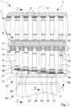
- a rotary tablet press machine 1 according to the invention is illustrated, that is arranged to produce tablets, lozenges, pills by compressing a product 50 in powder or granules for pharmaceutical, cosmetic, food or chemical use.
- the tablet press machine 1 comprises a compression turret 2 which is rotatable about an rotation axis X, in particular vertical, according to a rotation direction R and which includes a die table 3, provided along a circumferential portion or edge thereof with a plurality of dies 4, a plurality of lower punches 5 and a corresponding plurality of upper punches 6 associated in pairs with respective dies 4 and movable along a first direction T in order to compress the product 50 inserted into the dies 4 so as to obtain tablets, lozenges or pills.
- a compression turret 2 which is rotatable about an rotation axis X, in particular vertical, according to a rotation direction R and which includes a die table 3, provided along a circumferential portion or edge thereof with a plurality of dies 4, a plurality of lower punches 5 and a corresponding plurality of upper punches 6 associated in pairs with respective dies 4 and movable along a first direction T in order to compress the product 50 inserted into the dies 4
- the dies 4 are through cavities made in the die table 3 that form in cooperation with the punches 5, 6 the seats or housings in which the product 50 is dosed and subsequently compressed to form the tablets 100.
- the tablet press machine 1 comprises a dosing station 7 arranged to dispense a fixed amount of product 50 to be compressed inside the dies 4 and at least one compression station, of a known type and not illustrated in the figures, in which the lower punches 5 and the upper punches 6 are linearly moved inside the respective dies 4 to compress the product 50 delivered into the dies 4 so as to obtain the tablets.
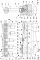
- the dosing station 7 comprises filling means 8 arranged to fill with the product 50 dosing cavities 40 formed by the dies 4 closed at the bottom by the lower punches 5 and having an settled filling depth L1 and cam means 10 cooperating with the lower punches 5 to move the latter ones inside the respective dies 4 and obtain the settled filling depth L1.
- Cam means 10 are fixed with respect to the compression turret 2 and are connected to a fixed supporting structure 30 of the tablet press machine 1.
- the filling means 8 comprise a container 38 containing the product 50 and open on the die table 3 to allow the product 50 to penetrate into the dosing cavities 40 in the respective dies 4.
- the depth or height of the dosing cavities 40 increases progressively during the rotation of the compression turret 2 in the rotation direction R, from a substantially zero value, when the dies 4, with the respective upper ends 16 of the lower punches 5 inserted therein, enter the container 38, to a value equal to the settled filling depth L1 when exiting the container 38.
- a scraper element is provided, of a known type and not illustrated in the figures, which is in sliding contact with an upper surface of the die table 3 in order to remove possible excess product 50 dosed in the dies 4.
- the cam means 10 comprise a first filling cam 21 provided with a first channel 25 and a second filling cam 22 provided with a second channel 26, said first channel 25 and said second channel 26 being configured and mutually arranged so as to guide follower ends 15 of the lower punches 5 along a filling profile or channel 27 defined by said first and second channel 25, 26.
- the second channel 26 is opposite the first channel 25 with respect to the lower punches 5.
- the tablet press machine 1 further comprises a first adjustment element 11 supporting the first filling cam 21 and a second adjustment element 12 supporting the second filling cam 22, which is mounted on said second adjustment element 12 slidably along an arc of circumference about the rotation axis X of the compression turret 2.
- the first filling cam 21 is mounted fixed on the first adjustment element 11.
- the first adjustment element 11 is slidably fixed to a supporting element 35 of the fixed supporting structure 30 of the tablet press machine 1.
- the second adjustment element 12 is configured to be moved with respect to the first adjustment element 11 along a first direction T parallel to the rotation axis X of the compression turret 2.
- the second adjustment element 12 is associated with and movably mounted with respect to the first adjustment element 11 along the first direction T.
- the tablet press machine 1 further comprises first driving means 13 configured to move with respect to the compression turret 2 and along the first direction T simultaneously the first adjustment element 11 supporting the first filling cam 21 and the second adjustment element 12 slidably supporting the second filling cam 22.
- the first filling cam 21 is the inner cam, i.e. the closest one to the rotation axis X, and the first channel 25 is therefore made on an outer side wall 21a of the first filling cam and open towards the outside of the tablet press machine 1.
- the second filling cam 22 is the outer cam, i.e. the farthest one from the rotation axis X, and the second channel 26 is therefore made on an inner side wall 22a of the second filling cam and open towards the inside of the tablet press machine 1.
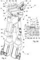
- the second filling cam 22 is further movable on, and along, the second adjustment element 12, rotating about the rotation axis X at least between a closed position B, in which it is substantially opposite the first filling cam 21 with the first channel 25 facing the second channel 26, and an open position A, in which said second filling cam 22 is positioned angularly spaced from, in particular adjacent to and immediately downstream of, said first filling cam 21, with reference to the rotation direction R.
- the second filling cam 22 is slidably supported by a supporting plane 12a of the second adjustment element 12.
- the first channel 25 of the first filling cam 21 comprises a first upper track 25a and a first lower track 25b
- the second channel 26 of the second filling cam 22 comprises a second upper track 26a and a second lower track 26b, said first tracks 25a, 25b and second tracks 26a, 26b being configured to abut and guide the follower ends 15 of the lower punches 5.
- the first channel 25, further comprises a first section 31 and a second section 32.
- the first channel 25 is converging having a width or height, i.e. a distance between the first upper track 25a and the first lower track 25b, that decreases in the rotation direction R. More precisely, the first channel 25 in the first section 31 has a first inlet height d1 (i.e. an inlet distance between the first upper track 25a and the second lower track 25b) such as to allow the follower ends 15 to selectively abut the first upper track 25a or the first lower track 25b, according to the position of the first filling cam 21, i.e. of the first adjustment element 11 along the first direction T, and a first outlet height d2 such as to maintain the follower ends 15 abutting substantially both first tracks 25a, 25b.
- a first inlet height d1 i.e. an inlet distance between the first upper track 25a and the second lower track 25b
- a first outlet height d2 such as to maintain the follower ends 15 abutting substantially both first tracks 25a, 25b.
- the inlet height d1 of the first channel 25 is bigger than an operating height h of the follower end 15 of the lower punch 5 to allow said follower end 15 to selectively abut the first upper track 25a or the first lower track 25b.
- the first channel 25 has a width or height, i.e. a distance between the second upper track 26a and the second lower track 26b, which is substantially constant and equal to the first outlet height d2 in the first section 31.
- the first upper track 25a in both sections 31, 32 is substantially straight and sloping towards, i.e. approaching, the first lower track 25b according to the rotation direction R of a predefined angle, in particular at the first section 31.
- the first lower track 25b is substantially perpendicular to the rotation axis X, in particular straight and horizontal, at the first section 31, while it is inclined with respect to the rotation axis X and parallel to the first upper track 25b at the second section 32.
- the first upper track 25a forms an inclination angle ⁇ with the supporting plane 12a of the second adjustment element 12, for example equal to about 5° (degree).
- the second channel 26 has a second inlet height or distance d1' such as to allow the follower ends 15 to selectively abut the second upper track 26a or the second lower track 26b, according to the angular position of the second filling cam 22 on the second adjustment element 12 and the position of the latter along the first direction T, and a second outlet height or distance d2' such as to maintain the follower ends 15 abutting substantially both second tracks 26a, 26b.
- the second channel 26 positioned downstream of the further first section 33 with reference to the rotation direction R, the second channel 26 has a distance between the second upper track 26a and the second lower track 26b substantially constant and equal to the second outlet height d2'.
- the second upper track 26a in both further sections 33, 34 is substantially straight and inclined with a slope towards, i.e. approaching, the second lower track 26b according to the rotation direction R, in particular at the further first section 33, and the second lower track 26b is substantially perpendicular to the rotation axis X, in particular straight and horizontal, at the further first section 33 while it is inclined with respect to the rotation axis X and parallel to the second upper track 26a at the further second section 34.
- first upper track 25a and the second upper track 26a are inclined with respect to the supporting plane 12a of the adjustment element 12 of the same inclination angle ⁇ .
- the inlet heights or distances d1, d1' and the outlet heights or distances d2, d2' respectively between the first tracks 25a, 25b of the first channel 25 and between the second tracks 26a, 26b of the second channel 26 are the same, and the first channel 25 and the second channel 26 are substantially the same and specular with respect to the lower punches, in particular with respect to a cylindrical geometric surface M passing through the longitudinal axes Y of the lower punches 5.
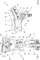
- the first driving means 13 are configured to move, with respect to the compression turret 2 and along the first direction T, the first adjustment element 11 (supporting the first filling cam 21 and the second adjustment element 12, which in turn slidably supports the second filling cam 22), in a plurality of positions between a raised position C and a lowered position D.
- the first lower track 25b of the first channel 25 of the first filling cam 21 is arranged to abut and slidably guide the follower ends 15 of the lower punches 5, and in the lowered position D, the first upper track 25a of the first channel 25 of the first filling cam 21 is arranged to abut and slidably guide the follower ends 15.
- the first driving means 13 are thus capable of moving the first filling cam 21 along a stroke of length S in a plurality of different working positions ( figure 3A ).
- the first driving means 13 comprise a first rotary electric motor 45 and first transmission means 41, for example of the screw-nut screw type, actuated by the said first electric motor 45 to linearly move the first adjustment element 11 along the first direction T.
- the first transmission means 41 comprise a nut screw fixed to the first adjustment element 11 and coupled with, and linearly moved by, a screw rotated by the first rotary electric motor 45.
- the first adjustment element 11 is also slidably coupled to the supporting element 35 of the fixed supporting structure 30 by means of a pair of rods 44.
- the tablet press machine 1 also comprises second driving means 14 configured to move by second transmission means 48 the second adjustment element 12 with respect to said first adjustment element 11 along the first direction T and autonomously with respect to said first adjustment element 11.
- the second driving means 14 are further configured to move through third transmission means 51, in a coordinated manner with respect to the first filling cam 21, the second filling cam 22 slidably above and along the second adjustment element 12 and in rotation about the rotation axis between the said open position A and said closed position B.
- the second upper track 26a of the second channel 26 is held parallel and coplanar to the first upper track 25a of the first channel 25.
- Coplanar means that the upper tracks 25a, 26a are consecutive and adjacent as well as inclined with respect to the supporting plane 12a of the second adjustment element 12 of the same inclination angle ⁇ as the upper tracks 25, 26.
- the second driving means 14 comprise, for example, a second rotary electric motor 47, the second transmission means 48 and the third transmission means 51 being actuated by the second electric motor 47 respectively to linearly move the second adjustment element 12 along the first direction T and to move the second filling cam 22 on the first adjustment element 12 along an arc of circumference whose centre is on the rotation axis X.
- the second transmission means 48 are, for example, of the screw-nut screw type and comprise respectively a nut screw fixed to the second adjustment element 12 and coupled with, and linearly moved by, a respective screw rotated by the second rotary electric motor 47 through an extendable cardan joint 49.
- the third transmission means 51 comprise, for example, a toothed sector that is made on the second filling cam 22, in particular on an outer side wall thereof that is opposite the inner side wall 22a, and engages, i.e. is in mesh, with a pinion 52 rotated by the second rotary electric motor 47 of the second driving means 14.
- the gear ratio between toothed sector and pinion 52 and transmission ratio between screw-nut screw of the second transmission means 48 are such as to allow the second filling cam 22 to be moved between the open position A and the closed position B while always maintaining the second upper track 26a parallel and coplanar to the first upper track 25a of the first filling cam 21.
- each lower punch 5 comprises a shaped annular protrusion, in particular having said operating height h, provided with opposite annular abutment faces 15a, 15b arranged to abut slidably the upper tracks 25a, 26a and/or the lower tracks 25b, 26b of the first and second channel 25, 26.
- the annular faces are inclined with respect to a longitudinal axis Y of the lower punch 5 of the same inclination angle as the sliding surfaces of the upper 25a, 26a and lower 25b, 26b tracks.
- the operating height h is the distance along the longitudinal axis Y between the upper and lower edges of the annular abutment faces 15a, 15b.
- each lower punch 5 comprises a pair of opposite rotating rollers with respect to the longitudinal axis Y and arranged to abut the upper tracks 25a, 26a and/or the lower tracks 25b, 26b of the first and second channel 25, 26.
- the tablet press machine 1 further comprises a fixed inlet cam 9 positioned upstream of the first filling cam 21 with reference to the rotation direction R and provided with an inlet track 28 adapted to support and slidably guide the follower ends 15 of the lower punches 5 at the inlet of the dosing station 7 towards the first channel 25 of the first filling cam 21.
- the inlet path 28 has a substantially linear and horizontal profile.
- the second adjustment element 12 comprises an outlet track 29 adapted to support and slidably guide the follower ends 15 of the lower punches 5 exiting the second filling cam 22 and having a substantially linear and horizontal profile.
- a filling distance F between the upper surfaces of the inlet track 28 and the outlet track 29 respectively, is the filling stroke of the lower punches 5 to form dosing chambers 40 in the dies 4 having the desired filling depth.
- cam means 10 to set the filling distance F, i.e. the stroke of the lower punches 5, so as to obtain dosing chambers 40 in the dies 4 having an settled and desired filling depth.
- the first adjustment element 11 supporting both filling cams 21, 22 is moved with respect to the compression turret 2 by the first driving means 13 along the first direction T and arranged at a fixed position between the possible positions comprised between the raised position C and the lowered position D.
- the second adjustment element 12 and the second filling cam 22 are moved with respect to the first filling cam 21 by the second driving means 14 in a coordinated manner respectively along the first direction T and along the second adjustment element 12 and about the rotation axis X of the compression turret 2, so as to position the second filling cam 22 at a respective settled position among the possible positions comprised between the open position A and the closed position B.
- Figures 1 to 6 illustrate a configuration of maximum filling C1 of cam means 10 which allows to obtain the maximum filling depth L1 of the dosing chamber 40.
- the first filling cam 21 fixed and moved by the first adjustment element 11 is arranged in the lowered position D and the second filling cam 22, slidably supported by the second adjustment element 12, is arranged in the open position A, creating a filling profile 27 having a maximum length.
- the follower ends 15 of the lower punches 5 during the rotation of the compression turret 2 abut and are slidably guided by the upper tracks 25a, 26a, in particular at the respective first sections 31, 33 of the channels 25, 26 of the filling cams 21, 22.
- the filling distance F between the sliding surfaces of the inlet track 28 and the outlet track 29 is equal to the maximum filling depth L1.
- Figures 7 and 8 illustrate a first configuration of intermediate filling C2 of cam means 10 which allow to obtain a first intermediate filling depth L2 of the dosing chamber 40.
- the first filling cam 21 is arranged in the raised position C and the second filling cam 22 is held in the open position A, creating a filling channel 27 having maximum length.
- the filling distance F between the sliding surfaces of the inlet track 28 and the outlet track 29 is equal to the first intermediate filling depth L2.
- Figures 9 to 12 illustrate a second configuration of intermediate filling C3 of cam means 10 which allows to obtain a second intermediate filling depth L3 of the dosing chamber 40, smaller than the first intermediate filling depth L2.
- the first filling cam 21 is arranged in the lowered position D and the second filling cam 22 is arranged in the closed position B, creating a filling channel 27 having a minimum length.
- the second channel 26 of the second filling cam 22 is facing in a substantially specular way the first channel 25 of the first filling cam 21 and the follower ends 15 of the lower punches 5 during the rotation of the compression turret 2 in the first sections 31, 33 of the channels 25, 26 of the filling cams 21, 22 abut and are slidably guided by both upper tracks 25a, 26a.
- the filling distance F between the upper sliding surfaces of the inlet track 28 and the outlet track 29 is equal to the second intermediate filling depth L3.
- Figures 13 and 14 illustrate a configuration of minimum filling C4 of cam means 10 which allows to obtain the minimum filling depth L4 of the dosing chamber 40.
- the first filling cam 21 is arranged in the raised position C and the second filling cam 22 is arranged in the closed position B, creating a filling channel 27 having a minimum length.
- the second channel 26 of the second filling cam 22 is facing in a substantially specular way the first channel 25 of the first filling cam 21 and the follower ends 15 of the lower punches 5 during the rotation of the compression turret 2 in the first sections 31, 33 of the channels 25, 26 of the respective filling cams 21, 22 abut and are slidably guided by the lower tracks 25b, 26b.
- the filling distance F between the sliding surfaces of the inlet track 28 and the outlet track 29 is equal to the minimum filling depth L4.
- the first adjustment element 11 i.e. the first filling cam 21 with respect to the compression turret 2 along the adjustment direction T, and the second filling cam 22 parallel and about the rotation axis X with respect to the first filling cam 21, it is possible to rapidly, simply and precisely obtain a plurality of different configurations of filling comprised between the configuration of maximum filling C1 and the configuration of minimum filling C4, i.e. it is possible to vary and adjust the filling depth from the maximum value L1 to the minimum value L2 in an almost continuous manner, with a minimum interval, for example equal to about 0.01 mm between one value and the next.
- Such an adjustment can be performed accurately and quickly by the driving means 13, 14 comprising two rotary electric motors 45, 47 controllable in rotation and speed with precision.
- the range of values between the maximum value L1 and the minimum value L2 may be, for example, about 14 mm, considering, for example, a maximum filling depth value L1 of 20 mm and a minimum filling depth value of 6 mm.
- This range of 14 mm can be obtained in traditional rotary filling machines by replacing the filling cam and necessarily using a suitable adjustment cam positioned downstream of the filling cam to obtain intermediate and/or more precise adjustments of the volume of dosing chamber 40.
- the adjustment cam allows to modify, in particular to reduce, the volume of dosing chambers 40, to bring the volume to the desired value, by suitably raising the lower punches 5 so as to allow the removal of the excess product.
- cam means 10 of tablet press machine 1 of the invention which allow a precise and accurate adjustment of the volume of dosing chambers 40 obtained in the dies 4 with the lower punches 5, it is not necessary to include a subsequent downstream adjustment cam in order to reduce the volume of dosing chambers 40, this making it possible to simplify the structure of the tablet press machine 1.
- the stopping times of the filling machine 1 of the invention are minimal, also due to the easy and fast adjustment of the position of filling cams 21, 22 by the driving means 13, 14.
Landscapes
- Engineering & Computer Science (AREA)
- Mechanical Engineering (AREA)
- Basic Packing Technique (AREA)
- Medical Preparation Storing Or Oral Administration Devices (AREA)
Claims (14)
- Dreh-Tablettenpressmaschine (1), aufweisend:- einen Kompressionsrevolver (2), der sich mit einer Drehrichtung (R) um eine Drehachse (X) dreht und einen Matrizentisch (3) beinhaltet, der entlang eines Umfangsabschnitts mit einer Mehrzahl von Matrizen (4), einer Mehrzahl von unteren Stempeln (5) und einer entsprechenden Mehrzahl von oberen Stempeln (6), die paarweise jeweiligen Matrizen (4) zugeordnet sind, versehen ist;- eine Dosierstation (7), die Füllmittel (8) zum Füllen von Dosierhohlräumen (40) mit einem Produkt (50) aufweist, die von den Matrizen (4) gebildet werden, die am Boden durch die unteren Stempel (5) geschlossen sind und eine festgelegte Fülltiefe (L1, L2, L3, L4) besitzen, und- Nockenmittel (10), die mit den unteren Stempeln (5) zusammenwirken, um die unteren Stempel innerhalb der jeweiligen Matrizen (4) zu bewegen und die festgelegte Fülltiefe (L1, L2, L3, L4) zu erhalten, wobei die Nockenmittel (10) einen ersten Füllnocken (21), der mit einem ersten Kanal (25) versehen ist, und einen zweiten Füllnocken (22), der mit einem zweiten Kanal (26) versehen ist, aufweisen, wobei der erste Kanal (25) und der zweite Kanal (26) so ausgebildet und gegenseitig angeordnet sind, dass sie Mitnehmerenden (15) der unteren Stempel (5) entlang eines Füllkanals (27) führen;dadurch gekennzeichnet, dass sie aufweist:- ein erstes Einstellelement (11), das den ersten Füllnocken (21) trägt, und ein zweites Einstellelement (12), das den zweiten Füllnocken (22) trägt, der auf dem zweiten Einstellelement (12) entlang eines Umfangsbogens um die Drehachse (X) gleitend angebracht ist, wobei das zweite Einstellelement (12) so ausgebildet ist, dass es in Bezug auf das erste Einstellelement (11) entlang einer ersten Richtung (T) parallel zu der Drehachse (X) bewegt werden kann;- erste Antriebsmittel (13), die so ausgebildet sind, dass sie in Bezug auf den Kompressionsrevolver (2) und entlang der ersten Richtung (T) gleichzeitig das erste Einstellelement (11), das den ersten Füllnocken (21) trägt, und das zweite Einstellelement (12), das den zweiten Füllnocken (22) gleitend trägt, bewegen; und- zweite Antriebsmittel (14), die so ausgebildet sind, dass sie in Bezug auf den ersten Füllnocken (21) das zweite Einstellelement (12) und den zweiten Füllnocken (22) in koordinierter Weise entlang der ersten Richtung (T) bzw. entlang des zweiten Einstellelements (12) und um die Drehachse (X) bewegen;wobei der erste Füllnocken (21) und der zweite Füllnocken (22) so ausgebildet sind, dass sie durch die ersten Antriebsmittel (13) und die zweiten Antriebsmittel (14) in Bezug aufeinander so positioniert werden, dass der erste Kanal (25) und der zweite Kanal (26) den Füllkanal (27) bilden, der eine solche Länge und ein solches Profil besitzt, dass er die erforderliche Verschiebung der unteren Stempel (5) ausführt, um die festgelegte Fülltiefe (L1, L2, L3, L4) zu erhalten, und wobei der erste Kanal (25) an einem seiner Enden für den Eintritt des unteren Stempels (5) eine Einlasshöhe (d1) besitzt, die größer ist als eine Arbeitshöhe (h) des Mitnehmerendes (15) des unteren Stempels (5).
- Tablettenpressmaschine (1) nach Anspruch 1, wobei der zweite Füllnocken (22) zumindest zwischen einer geschlossenen Position (B), in der er dem ersten Füllnocken (21) im Wesentlichen gegenüberliegt, wobei der erste Kanal (25) dem zweiten Kanal (26) zugewandt ist, und einer offenen Position (A), in der der zweite Füllnocken (22) winkelmäßig beabstandet von dem ersten Füllnocken (21) positioniert ist, bewegbar ist.
- Tablettenpressmaschine (1) nach einem der vorhergehenden Ansprüche, wobei der erste Kanal (25) eine erste obere Bahn (25a) und eine erste untere Bahn (25b) aufweist und der zweite Kanal (26) eine zweite obere Bahn (26a) und eine zweite untere Bahn (26b) aufweist, wobei die ersten und zweiten Bahnen (25a, 25b, 26a, 26b) so ausgebildet sind, dass sie an den Mitnehmerenden (15) der unteren Stempel (5) anliegen.
- Tablettenpressmaschine (1) nach Anspruch 3, wobei der erste Kanal (25) einen ersten Abschnitt (31) und einen zweiten Abschnitt (32) aufweist, wobei der erste Kanal (25) in dem ersten Abschnitt (31) konvergent ist und einen Abstand zwischen der ersten oberen und unteren Bahn (25a, 25b) besitzt, der in der Drehrichtung (R) abnimmt, mit einer Einlasshöhe (d1) des ersten Kanals (25), so dass die Mitnehmerenden (15) an der ersten oberen Bahn (25a) oder der ersten unteren Bahn (25b) anliegen können, und einer Auslasshöhe (d2) des ersten Kanals (25), so dass die Mitnehmerenden (15) im Wesentlichen sowohl an der ersten oberen als auch an der ersten unteren Bahn (25a, 25b) anliegen, wobei der erste Kanal (25) in dem zweiten Abschnitt (32), der in Bezug auf die Drehrichtung (R) stromabwärts des ersten Abschnitts (31) angeordnet ist, einen Abstand zwischen der ersten oberen und der ersten unteren Bahn (25a, 25b) besitzt, der im Wesentlichen konstant und gleich der Auslasshöhe (d2) ist.
- Tablettenpressmaschine (1) nach Anspruch 4, wobei die erste obere Bahn (25a) im Wesentlichen gerade und geneigt ist, und mit einer Neigung in Richtung der ersten unteren Bahn (25b) in dem ersten Abschnitt (31) gemäß der Drehrichtung (R), und die erste untere Bahn (25b) in dem ersten Abschnitt (31) im Wesentlichen senkrecht zu der Drehachse (X) ist, während sie in dem zweiten Abschnitt (32) in Bezug auf die Drehachse (X) geneigt und parallel zu der ersten oberen Bahn (25a) ist.
- Tablettenpressmaschine (1) nach einem der Ansprüche 3 bis 5, wobei der zweite Kanal (26) einen weiteren ersten Abschnitt (33) und einen weiteren zweiten Abschnitt (34) aufweist, wobei der zweite Kanal (26) in dem weiteren ersten Abschnitt (33) konvergent ist und einen Abstand zwischen der zweiten oberen und unteren Bahn (26a, 26b) besitzt, der in der Drehrichtung (R) abnimmt, mit einer weiteren Einlasshöhe (d1') des zweiten Kanals (26), so dass die Mitnehmerenden (15) an der zweiten oberen Bahn (26a) oder der zweiten unteren Bahn (26b) anliegen können, und einer weiteren Auslasshöhe (d2') des zweiten Kanals (26), so dass die Mitnehmerenden (15) im Wesentlichen sowohl an der zweiten oberen als auch an der zweiten unteren Bahn (26a, 26b) anliegen, wobei der zweite Kanal (26) in dem weiteren zweiten Abschnitt (34), der in Bezug auf die Drehrichtung (R) stromabwärts des weiteren ersten Abschnitts (33) angeordnet ist, einen Abstand zwischen den zweiten Bahnen (26a, 26b) besitzt, der im Wesentlichen konstant und gleich der weiteren Auslasshöhe (d2') ist.
- Tablettenpressmaschine (1) nach Anspruch 6, wobei die zweite obere Bahn (26a) im Wesentlichen gerade und geneigt ist, und mit einer Neigung in Richtung der zweiten unteren Bahn (26b) in dem weiteren ersten Abschnitt (33), gemäß der Drehrichtung (R), und die zweite untere Bahn (26b) in dem weiteren ersten Abschnitt (33) im Wesentlichen senkrecht zu der Drehachse (X) ist, während sie in dem weiteren zweiten Abschnitt (34) in Bezug auf die Drehachse (X) geneigt und parallel zu der zweiten oberen Bahn (26a) ist.
- Tablettenpressmaschine (1) nach einem der Ansprüche 3 bis 7, wobei die erste obere Bahn (25a) und die zweite obere Bahn (26a) in Bezug auf eine Stützebene (12a) des zweiten Einstellelements (12) um den selben Neigungswinkel (α) geneigt sind.
- Tablettenpressmaschine (1) nach einem der vorhergehenden Ansprüche, aufweisend zweite Antriebsmittel (14), die so ausgebildet sind, dass sie durch zweite Übertragungsmittel (48) das zweite Einstellelement (12) in Bezug auf das erste Einstellelement (11) entlang der ersten Richtung (T) bewegen.
- Tablettenpressmaschine (1) nach Anspruch 9, wobei die zweiten Antriebsmittel (14) zudem so ausgebildet sind, dass sie durch dritte Übertragungsmittel (51) in einer koordinierten Weise in Bezug auf den ersten Füllnocken (21) den zweiten Füllnocken (22) gleitend auf dem zweiten Einstellelement (12) bewegen.
- Tablettenpressmaschine (1) nach Anspruch 10, wobei die dritten Übertragungsmittel (51) einen an dem zweiten Füllnocken (22) ausgebildeten Zahnsektor und ein Ritzel (52) aufweisen, die miteinander in Eingriff stehen, wobei das Ritzel (52) durch die zweiten Antriebsmittel (14) gedreht wird.
- Tablettenpressmaschine (1) nach einem der vorhergehenden Ansprüche, wobei der erste Füllnocken (21) fest an dem ersten Einstellelement (11) angebracht ist.
- Tablettenpressmaschine (1) nach einem der vorhergehenden Ansprüche, wobei das zweite Einstellelement (12) eine Auslassbahn (29) aufweist, die ausgebildet ist, die aus dem zweiten Füllnocken (22) austretenden Mitnehmerenden (15) der unteren Stempel (5) zu tragen und gleitend zu führen, und die ein im Wesentlichen lineares und horizontales Profil aufweist, wobei ein Füllabstand (F) zwischen oberen Gleitflächen einer Einlassbahn (28), die stromaufwärts des ersten Füllnockens (21) angeordnet ist, und der Auslassbahn (29), mit einem Hub der unteren Stempel (5) entlang der ersten Richtung (T) zusammenfällt, um die Dosierkammern (40) in den Matrizen (4) mit einer festgelegten Fülltiefe (L1, L2, L3, L4) zu bilden.
- Tablettenpressmaschine (1) nach einem der vorhergehenden Ansprüche, wobei das Mitnehmerende (15) jedes unteren Stempels (5) einen geformten ringförmigen Vorsprung aufweist, der mit gegenüberliegenden ringförmigen Anschlagflächen (15a, 15b) versehen ist, die so angeordnet sind, dass sie gleitend an den Kanälen (25, 26) anliegen.
Priority Applications (2)
| Application Number | Priority Date | Filing Date | Title |
|---|---|---|---|
| RS20241110A RS66029B1 (sr) | 2020-01-08 | 2021-01-07 | Mašina za presovanje tableta |
| HRP20241230TT HRP20241230T1 (hr) | 2020-01-08 | 2021-01-07 | Stroj za prešanje tableta |
Applications Claiming Priority (2)
| Application Number | Priority Date | Filing Date | Title |
|---|---|---|---|
| IT102020000000112A IT202000000112A1 (it) | 2020-01-08 | 2020-01-08 | Macchina comprimitrice. |
| PCT/IB2021/050088 WO2021140455A1 (en) | 2020-01-08 | 2021-01-07 | Tablet press machine |
Publications (3)
| Publication Number | Publication Date |
|---|---|
| EP4087724A1 EP4087724A1 (de) | 2022-11-16 |
| EP4087724B1 true EP4087724B1 (de) | 2024-07-10 |
| EP4087724C0 EP4087724C0 (de) | 2024-07-10 |
Family
ID=70228669
Family Applications (1)
| Application Number | Title | Priority Date | Filing Date |
|---|---|---|---|
| EP21702710.1A Active EP4087724B1 (de) | 2020-01-08 | 2021-01-07 | Tablettierungsmaschine |
Country Status (12)
| Country | Link |
|---|---|
| US (1) | US12172401B2 (de) |
| EP (1) | EP4087724B1 (de) |
| JP (1) | JP7449388B2 (de) |
| KR (1) | KR102702664B1 (de) |
| CN (1) | CN114929464B (de) |
| CA (1) | CA3163457A1 (de) |
| ES (1) | ES2993318T3 (de) |
| HR (1) | HRP20241230T1 (de) |
| IT (1) | IT202000000112A1 (de) |
| PL (1) | PL4087724T3 (de) |
| RS (1) | RS66029B1 (de) |
| WO (1) | WO2021140455A1 (de) |
Families Citing this family (2)
| Publication number | Priority date | Publication date | Assignee | Title |
|---|---|---|---|---|
| IT201900019649A1 (it) * | 2019-10-23 | 2021-04-23 | Ima Spa | Macchina comprimitrice e metodo di compressione. |
| CN113910668B (zh) * | 2021-10-04 | 2022-07-01 | 丽申药业股份有限公司 | 一种复合酶片剂生产制备方法 |
Family Cites Families (27)
| Publication number | Priority date | Publication date | Assignee | Title |
|---|---|---|---|---|
| US3861322A (en) | 1972-09-06 | 1975-01-21 | Danly Machine Corp | Friction drive loader |
| DE3628757A1 (de) * | 1986-08-23 | 1988-03-03 | Fette Wilhelm Gmbh | Verfahren zur qualitaetssicherung bei der herstellung von tabletten |
| JPH0721293A (ja) | 1993-07-07 | 1995-01-24 | Fujitsu Ltd | 自動取引処理装置 |
| JPH0739517Y2 (ja) * | 1993-08-30 | 1995-09-13 | 株式会社畑鉄工所 | 回転式粉末圧縮成型機 |
| JPH0739513Y2 (ja) * | 1993-09-07 | 1995-09-13 | 株式会社畑鉄工所 | 回転式粉末圧縮成型機 |
| IT1264747B1 (it) | 1993-12-10 | 1996-10-04 | Ima Spa | Macchina comprimitrice rotativa |
| IT1274883B (it) * | 1994-08-05 | 1997-07-25 | Ima Spa | Dispositivo di dosaggio in macchine comprimitrici per la realizzazionedi compresse. |
| CN1122594C (zh) * | 1995-12-29 | 2003-10-01 | I.M.A.工业机器自动化股份公司 | 制药片压片机用的配料装置 |
| KR200174102Y1 (ko) * | 1999-10-19 | 2000-03-15 | 주식회사세종기계 | 로타리식 정제 압축성형기 |
| JP2005505436A (ja) * | 2001-03-19 | 2005-02-24 | セバル エス.アー.エス. | 連続的に作動する工作機械により裾部に頭部を成型しつつプラスチック製軟質チューブを製造する製造設備 |
| US6742646B2 (en) * | 2001-09-28 | 2004-06-01 | Mcneil-Ppc, Inc. | Systems, methods and apparatuses for manufacturing dosage forms |
| JP3776360B2 (ja) * | 2002-02-06 | 2006-05-17 | 本田技研工業株式会社 | 粉末成形プレスの成形体払出機構 |
| JP3729791B2 (ja) * | 2002-04-17 | 2005-12-21 | 株式会社畑鉄工所 | 回転式粉末圧縮成型機及び上杵 |
| JP4022161B2 (ja) | 2003-03-25 | 2007-12-12 | 日東電工株式会社 | 回転圧縮成形機 |
| JP2006289440A (ja) * | 2005-04-11 | 2006-10-26 | Tdk Corp | ロータリープレス装置 |
| CN100473521C (zh) * | 2006-03-31 | 2009-04-01 | Tdk株式会社 | 成形装置 |
| DE102006017196B4 (de) * | 2006-04-12 | 2008-09-11 | Fette Gmbh | Verfahren zur Regelung der Wirkstoffmenge von Tabletten während der Produktion in einer Rundläufertablettenpresse |
| DE102006020214B3 (de) * | 2006-05-02 | 2007-12-27 | Fette Gmbh | Vorrichtung zur Führung von Unterstempeln |
| US7553436B2 (en) * | 2007-11-02 | 2009-06-30 | Metropolitan Computing Corporation | System and method for optimizing tablet formation by a rotary press machine |
| DE102007057790B4 (de) * | 2007-11-30 | 2011-02-10 | Fette Gmbh | Rundlaufpresse |
| DE102008049015B4 (de) * | 2008-09-25 | 2013-10-31 | Fette Compacting Gmbh | Verfahren zur Qualitätsüberwachung von pulverförmigem Pressmaterial und eine Rundläuferpresse zur Durchführung des Verfahrens |
| CN101758233A (zh) * | 2008-11-21 | 2010-06-30 | 扬州市海力精密机械制造有限公司 | 一种粉末成型机顶压机构 |
| US20110024937A1 (en) * | 2009-07-30 | 2011-02-03 | Semen Dukler | Tablet Formation System for Fully-Loaded Presses |
| ITMO20130324A1 (it) | 2013-11-29 | 2015-05-30 | Sacmi | Apparato di formatura |
| KR101706727B1 (ko) * | 2015-10-20 | 2017-02-16 | 주식회사 세종파마텍 | 정제펀치타정기의 중량조절장치 |
| KR101820671B1 (ko) * | 2016-10-04 | 2018-01-22 | 한일너클프레스 주식회사 | 스트로크 조절이 용이한 너클 프레스 |
| CN209738366U (zh) * | 2019-01-14 | 2019-12-06 | 北京新龙立科技有限公司 | 一种双色片气动出片装置 |
-
2020
- 2020-01-08 IT IT102020000000112A patent/IT202000000112A1/it unknown
-
2021
- 2021-01-07 HR HRP20241230TT patent/HRP20241230T1/hr unknown
- 2021-01-07 ES ES21702710T patent/ES2993318T3/es active Active
- 2021-01-07 PL PL21702710.1T patent/PL4087724T3/pl unknown
- 2021-01-07 US US17/791,449 patent/US12172401B2/en active Active
- 2021-01-07 WO PCT/IB2021/050088 patent/WO2021140455A1/en not_active Ceased
- 2021-01-07 JP JP2022541993A patent/JP7449388B2/ja active Active
- 2021-01-07 RS RS20241110A patent/RS66029B1/sr unknown
- 2021-01-07 CA CA3163457A patent/CA3163457A1/en active Pending
- 2021-01-07 KR KR1020227026513A patent/KR102702664B1/ko active Active
- 2021-01-07 EP EP21702710.1A patent/EP4087724B1/de active Active
- 2021-01-07 CN CN202180008577.5A patent/CN114929464B/zh active Active
Also Published As
| Publication number | Publication date |
|---|---|
| JP2023509193A (ja) | 2023-03-07 |
| JP7449388B2 (ja) | 2024-03-13 |
| ES2993318T3 (en) | 2024-12-27 |
| WO2021140455A1 (en) | 2021-07-15 |
| CN114929464B (zh) | 2024-07-05 |
| HRP20241230T1 (hr) | 2024-11-22 |
| RS66029B1 (sr) | 2024-11-29 |
| US12172401B2 (en) | 2024-12-24 |
| US20230041286A1 (en) | 2023-02-09 |
| PL4087724T3 (pl) | 2024-11-18 |
| KR20220120681A (ko) | 2022-08-30 |
| EP4087724A1 (de) | 2022-11-16 |
| CN114929464A (zh) | 2022-08-19 |
| EP4087724C0 (de) | 2024-07-10 |
| IT202000000112A1 (it) | 2021-07-08 |
| CA3163457A1 (en) | 2021-07-15 |
| KR102702664B1 (ko) | 2024-09-05 |
Similar Documents
| Publication | Publication Date | Title |
|---|---|---|
| US3561054A (en) | Powder compacting press | |
| EP4087724B1 (de) | Tablettierungsmaschine | |
| DE2438316C2 (de) | Maschine zum teilen und wirken von teigstuecken | |
| DE3842274A1 (de) | Verdichtungsmaschine zur herstellung von tabletten | |
| CN109987263B (zh) | 一种灌装设备 | |
| EP0766620B1 (de) | Dosiervorrichtung für eine tablettierpresse | |
| US20070248711A1 (en) | Portioning unit | |
| US12466149B2 (en) | Filling unit for a rotary press and a method for providing an optimized rotary press | |
| US20220396047A1 (en) | Tablet press machine and compression method | |
| US3408963A (en) | Tablet machine | |
| US5910324A (en) | Device for the manufacture of tablets | |
| KR20080015869A (ko) | 회전식 펠릿 장치 및 다층 펠릿의 제조 방법 | |
| DE2454168B2 (de) | Tablettenpresse fuer pulver- oder granulatfoermiges material mit umlaufendem matrizenring | |
| CN1122594C (zh) | 制药片压片机用的配料装置 | |
| CN118020805A (zh) | 一种仿手工糕点包馅设备 | |
| US2727473A (en) | Coating mechanism | |
| US3384035A (en) | Industrial process and apparatus | |
| WO2022229770A1 (en) | Rotary press machine for the production of pressed products | |
| JP7570695B2 (ja) | 食品生地の分割装置 | |
| CN209768762U (zh) | 饺子成型设备 | |
| CN2469720Y (zh) | 食品成型机 | |
| DE2748988C2 (de) | Teigteilmaschine | |
| CN222522128U (zh) | 一种连续压片设备 | |
| CN109156499A (zh) | 一种鱼丸机 | |
| CN119217775A (zh) | 药品制造用高速压片机 |
Legal Events
| Date | Code | Title | Description |
|---|---|---|---|
| STAA | Information on the status of an ep patent application or granted ep patent |
Free format text: STATUS: UNKNOWN |
|
| STAA | Information on the status of an ep patent application or granted ep patent |
Free format text: STATUS: THE INTERNATIONAL PUBLICATION HAS BEEN MADE |
|
| PUAI | Public reference made under article 153(3) epc to a published international application that has entered the european phase |
Free format text: ORIGINAL CODE: 0009012 |
|
| STAA | Information on the status of an ep patent application or granted ep patent |
Free format text: STATUS: REQUEST FOR EXAMINATION WAS MADE |
|
| 17P | Request for examination filed |
Effective date: 20220704 |
|
| AK | Designated contracting states |
Kind code of ref document: A1 Designated state(s): AL AT BE BG CH CY CZ DE DK EE ES FI FR GB GR HR HU IE IS IT LI LT LU LV MC MK MT NL NO PL PT RO RS SE SI SK SM TR |
|
| DAV | Request for validation of the european patent (deleted) | ||
| DAX | Request for extension of the european patent (deleted) | ||
| P01 | Opt-out of the competence of the unified patent court (upc) registered |
Effective date: 20230509 |
|
| STAA | Information on the status of an ep patent application or granted ep patent |
Free format text: STATUS: EXAMINATION IS IN PROGRESS |
|
| 17Q | First examination report despatched |
Effective date: 20231031 |
|
| GRAP | Despatch of communication of intention to grant a patent |
Free format text: ORIGINAL CODE: EPIDOSNIGR1 |
|
| STAA | Information on the status of an ep patent application or granted ep patent |
Free format text: STATUS: GRANT OF PATENT IS INTENDED |
|
| INTG | Intention to grant announced |
Effective date: 20240201 |
|
| GRAS | Grant fee paid |
Free format text: ORIGINAL CODE: EPIDOSNIGR3 |
|
| GRAA | (expected) grant |
Free format text: ORIGINAL CODE: 0009210 |
|
| STAA | Information on the status of an ep patent application or granted ep patent |
Free format text: STATUS: THE PATENT HAS BEEN GRANTED |
|
| AK | Designated contracting states |
Kind code of ref document: B1 Designated state(s): AL AT BE BG CH CY CZ DE DK EE ES FI FR GB GR HR HU IE IS IT LI LT LU LV MC MK MT NL NO PL PT RO RS SE SI SK SM TR |
|
| REG | Reference to a national code |
Ref country code: CH Ref legal event code: EP |
|
| REG | Reference to a national code |
Ref country code: DE Ref legal event code: R096 Ref document number: 602021015449 Country of ref document: DE |
|
| U01 | Request for unitary effect filed |
Effective date: 20240723 |
|
| P04 | Withdrawal of opt-out of the competence of the unified patent court (upc) registered |
Free format text: CASE NUMBER: APP_44106/2024 Effective date: 20240729 |
|
| U07 | Unitary effect registered |
Designated state(s): AT BE BG DE DK EE FI FR IT LT LU LV MT NL PT SE SI Effective date: 20240731 |
|
| REG | Reference to a national code |
Ref country code: HR Ref legal event code: T1PR Ref document number: P20241230 Country of ref document: HR |
|
| REG | Reference to a national code |
Ref country code: ES Ref legal event code: FG2A Ref document number: 2993318 Country of ref document: ES Kind code of ref document: T3 Effective date: 20241227 |
|
| P05 | Withdrawal of opt-out of the competence of the unified patent court (upc) changed |
Free format text: CASE NUMBER: APP_44106/2024 Effective date: 20240731 |
|
| PG25 | Lapsed in a contracting state [announced via postgrant information from national office to epo] |
Ref country code: NO Free format text: LAPSE BECAUSE OF FAILURE TO SUBMIT A TRANSLATION OF THE DESCRIPTION OR TO PAY THE FEE WITHIN THE PRESCRIBED TIME-LIMIT Effective date: 20241010 |
|
| PG25 | Lapsed in a contracting state [announced via postgrant information from national office to epo] |
Ref country code: GR Free format text: LAPSE BECAUSE OF FAILURE TO SUBMIT A TRANSLATION OF THE DESCRIPTION OR TO PAY THE FEE WITHIN THE PRESCRIBED TIME-LIMIT Effective date: 20241011 |
|
| PG25 | Lapsed in a contracting state [announced via postgrant information from national office to epo] |
Ref country code: IS Free format text: LAPSE BECAUSE OF FAILURE TO SUBMIT A TRANSLATION OF THE DESCRIPTION OR TO PAY THE FEE WITHIN THE PRESCRIBED TIME-LIMIT Effective date: 20241110 |
|
| PG25 | Lapsed in a contracting state [announced via postgrant information from national office to epo] |
Ref country code: NO Free format text: LAPSE BECAUSE OF FAILURE TO SUBMIT A TRANSLATION OF THE DESCRIPTION OR TO PAY THE FEE WITHIN THE PRESCRIBED TIME-LIMIT Effective date: 20241010 Ref country code: IS Free format text: LAPSE BECAUSE OF FAILURE TO SUBMIT A TRANSLATION OF THE DESCRIPTION OR TO PAY THE FEE WITHIN THE PRESCRIBED TIME-LIMIT Effective date: 20241110 Ref country code: GR Free format text: LAPSE BECAUSE OF FAILURE TO SUBMIT A TRANSLATION OF THE DESCRIPTION OR TO PAY THE FEE WITHIN THE PRESCRIBED TIME-LIMIT Effective date: 20241011 |
|
| REG | Reference to a national code |
Ref country code: HR Ref legal event code: ODRP Ref document number: P20241230 Country of ref document: HR Payment date: 20250305 Year of fee payment: 5 |
|
| U21 | Renewal fee for the european patent with unitary effect paid with additional fee |
Year of fee payment: 5 Effective date: 20250224 |
|
| PGFP | Annual fee paid to national office [announced via postgrant information from national office to epo] |
Ref country code: HR Payment date: 20250305 Year of fee payment: 5 |
|
| PG25 | Lapsed in a contracting state [announced via postgrant information from national office to epo] |
Ref country code: SM Free format text: LAPSE BECAUSE OF FAILURE TO SUBMIT A TRANSLATION OF THE DESCRIPTION OR TO PAY THE FEE WITHIN THE PRESCRIBED TIME-LIMIT Effective date: 20240710 |
|
| PGFP | Annual fee paid to national office [announced via postgrant information from national office to epo] |
Ref country code: ES Payment date: 20250211 Year of fee payment: 5 |
|
| PGFP | Annual fee paid to national office [announced via postgrant information from national office to epo] |
Ref country code: CH Payment date: 20250306 Year of fee payment: 5 |
|
| PG25 | Lapsed in a contracting state [announced via postgrant information from national office to epo] |
Ref country code: CZ Free format text: LAPSE BECAUSE OF FAILURE TO SUBMIT A TRANSLATION OF THE DESCRIPTION OR TO PAY THE FEE WITHIN THE PRESCRIBED TIME-LIMIT Effective date: 20240710 |
|
| PGFP | Annual fee paid to national office [announced via postgrant information from national office to epo] |
Ref country code: PL Payment date: 20250115 Year of fee payment: 5 |
|
| PG25 | Lapsed in a contracting state [announced via postgrant information from national office to epo] |
Ref country code: SK Free format text: LAPSE BECAUSE OF FAILURE TO SUBMIT A TRANSLATION OF THE DESCRIPTION OR TO PAY THE FEE WITHIN THE PRESCRIBED TIME-LIMIT Effective date: 20240710 |
|
| PGFP | Annual fee paid to national office [announced via postgrant information from national office to epo] |
Ref country code: GB Payment date: 20250217 Year of fee payment: 5 |
|
| PGFP | Annual fee paid to national office [announced via postgrant information from national office to epo] |
Ref country code: RS Payment date: 20250303 Year of fee payment: 5 |
|
| PGFP | Annual fee paid to national office [announced via postgrant information from national office to epo] |
Ref country code: TR Payment date: 20250310 Year of fee payment: 5 |
|
| PLBE | No opposition filed within time limit |
Free format text: ORIGINAL CODE: 0009261 |
|
| STAA | Information on the status of an ep patent application or granted ep patent |
Free format text: STATUS: NO OPPOSITION FILED WITHIN TIME LIMIT |
|
| 26N | No opposition filed |
Effective date: 20250411 |
|
| PG25 | Lapsed in a contracting state [announced via postgrant information from national office to epo] |
Ref country code: MC Free format text: LAPSE BECAUSE OF FAILURE TO SUBMIT A TRANSLATION OF THE DESCRIPTION OR TO PAY THE FEE WITHIN THE PRESCRIBED TIME-LIMIT Effective date: 20240710 |