EP4079685A1 - Verfahren zur herstellung eines lithium-eisen-mangan-phosphat-vorläufers und verfahren zur herstellung von lithium-eisen-mangan-phosphat - Google Patents
Verfahren zur herstellung eines lithium-eisen-mangan-phosphat-vorläufers und verfahren zur herstellung von lithium-eisen-mangan-phosphat Download PDFInfo
- Publication number
- EP4079685A1 EP4079685A1 EP20903373.7A EP20903373A EP4079685A1 EP 4079685 A1 EP4079685 A1 EP 4079685A1 EP 20903373 A EP20903373 A EP 20903373A EP 4079685 A1 EP4079685 A1 EP 4079685A1
- Authority
- EP
- European Patent Office
- Prior art keywords
- manganese phosphate
- iron manganese
- lithium iron
- lithium
- liquid material
- Prior art date
- Legal status (The legal status is an assumption and is not a legal conclusion. Google has not performed a legal analysis and makes no representation as to the accuracy of the status listed.)
- Pending
Links
Images

Classifications
-
- C—CHEMISTRY; METALLURGY
- C01—INORGANIC CHEMISTRY
- C01B—NON-METALLIC ELEMENTS; COMPOUNDS THEREOF; METALLOIDS OR COMPOUNDS THEREOF NOT COVERED BY SUBCLASS C01C
- C01B25/00—Phosphorus; Compounds thereof
- C01B25/16—Oxyacids of phosphorus; Salts thereof
- C01B25/26—Phosphates
- C01B25/45—Phosphates containing plural metal, or metal and ammonium
-
- B—PERFORMING OPERATIONS; TRANSPORTING
- B82—NANOTECHNOLOGY
- B82Y—SPECIFIC USES OR APPLICATIONS OF NANOSTRUCTURES; MEASUREMENT OR ANALYSIS OF NANOSTRUCTURES; MANUFACTURE OR TREATMENT OF NANOSTRUCTURES
- B82Y30/00—Nanotechnology for materials or surface science, e.g. nanocomposites
-
- B—PERFORMING OPERATIONS; TRANSPORTING
- B82—NANOTECHNOLOGY
- B82Y—SPECIFIC USES OR APPLICATIONS OF NANOSTRUCTURES; MEASUREMENT OR ANALYSIS OF NANOSTRUCTURES; MANUFACTURE OR TREATMENT OF NANOSTRUCTURES
- B82Y40/00—Manufacture or treatment of nanostructures
-
- C—CHEMISTRY; METALLURGY
- C07—ORGANIC CHEMISTRY
- C07C—ACYCLIC OR CARBOCYCLIC COMPOUNDS
- C07C51/00—Preparation of carboxylic acids or their salts, halides or anhydrides
- C07C51/41—Preparation of salts of carboxylic acids
- C07C51/412—Preparation of salts of carboxylic acids by conversion of the acids, their salts, esters or anhydrides with the same carboxylic acid part
-
- H—ELECTRICITY
- H01—ELECTRIC ELEMENTS
- H01M—PROCESSES OR MEANS, e.g. BATTERIES, FOR THE DIRECT CONVERSION OF CHEMICAL ENERGY INTO ELECTRICAL ENERGY
- H01M10/00—Secondary cells; Manufacture thereof
- H01M10/05—Accumulators with non-aqueous electrolyte
- H01M10/052—Li-accumulators
-
- H—ELECTRICITY
- H01—ELECTRIC ELEMENTS
- H01M—PROCESSES OR MEANS, e.g. BATTERIES, FOR THE DIRECT CONVERSION OF CHEMICAL ENERGY INTO ELECTRICAL ENERGY
- H01M4/00—Electrodes
- H01M4/02—Electrodes composed of, or comprising, active material
- H01M4/13—Electrodes for accumulators with non-aqueous electrolyte, e.g. for lithium-accumulators; Processes of manufacture thereof
- H01M4/136—Electrodes based on inorganic compounds other than oxides or hydroxides, e.g. sulfides, selenides, tellurides, halogenides or LiCoFy
-
- H—ELECTRICITY
- H01—ELECTRIC ELEMENTS
- H01M—PROCESSES OR MEANS, e.g. BATTERIES, FOR THE DIRECT CONVERSION OF CHEMICAL ENERGY INTO ELECTRICAL ENERGY
- H01M4/00—Electrodes
- H01M4/02—Electrodes composed of, or comprising, active material
- H01M4/36—Selection of substances as active materials, active masses, active liquids
- H01M4/58—Selection of substances as active materials, active masses, active liquids of inorganic compounds other than oxides or hydroxides, e.g. sulfides, selenides, tellurides, halogenides or LiCoFy; of polyanionic structures, e.g. phosphates, silicates or borates
- H01M4/5825—Oxygenated metallic salts or polyanionic structures, e.g. borates, phosphates, silicates, olivines
-
- C—CHEMISTRY; METALLURGY
- C01—INORGANIC CHEMISTRY
- C01P—INDEXING SCHEME RELATING TO STRUCTURAL AND PHYSICAL ASPECTS OF SOLID INORGANIC COMPOUNDS
- C01P2004/00—Particle morphology
- C01P2004/60—Particles characterised by their size
-
- C—CHEMISTRY; METALLURGY
- C01—INORGANIC CHEMISTRY
- C01P—INDEXING SCHEME RELATING TO STRUCTURAL AND PHYSICAL ASPECTS OF SOLID INORGANIC COMPOUNDS
- C01P2004/00—Particle morphology
- C01P2004/60—Particles characterised by their size
- C01P2004/61—Micrometer sized, i.e. from 1-100 micrometer
-
- C—CHEMISTRY; METALLURGY
- C01—INORGANIC CHEMISTRY
- C01P—INDEXING SCHEME RELATING TO STRUCTURAL AND PHYSICAL ASPECTS OF SOLID INORGANIC COMPOUNDS
- C01P2004/00—Particle morphology
- C01P2004/60—Particles characterised by their size
- C01P2004/62—Submicrometer sized, i.e. from 0.1-1 micrometer
-
- C—CHEMISTRY; METALLURGY
- C01—INORGANIC CHEMISTRY
- C01P—INDEXING SCHEME RELATING TO STRUCTURAL AND PHYSICAL ASPECTS OF SOLID INORGANIC COMPOUNDS
- C01P2004/00—Particle morphology
- C01P2004/60—Particles characterised by their size
- C01P2004/64—Nanometer sized, i.e. from 1-100 nanometer
-
- C—CHEMISTRY; METALLURGY
- C01—INORGANIC CHEMISTRY
- C01P—INDEXING SCHEME RELATING TO STRUCTURAL AND PHYSICAL ASPECTS OF SOLID INORGANIC COMPOUNDS
- C01P2006/00—Physical properties of inorganic compounds
- C01P2006/40—Electric properties
-
- H—ELECTRICITY
- H01—ELECTRIC ELEMENTS
- H01M—PROCESSES OR MEANS, e.g. BATTERIES, FOR THE DIRECT CONVERSION OF CHEMICAL ENERGY INTO ELECTRICAL ENERGY
- H01M4/00—Electrodes
- H01M4/02—Electrodes composed of, or comprising, active material
- H01M2004/021—Physical characteristics, e.g. porosity, surface area
-
- H—ELECTRICITY
- H01—ELECTRIC ELEMENTS
- H01M—PROCESSES OR MEANS, e.g. BATTERIES, FOR THE DIRECT CONVERSION OF CHEMICAL ENERGY INTO ELECTRICAL ENERGY
- H01M4/00—Electrodes
- H01M4/02—Electrodes composed of, or comprising, active material
- H01M2004/026—Electrodes composed of, or comprising, active material characterised by the polarity
- H01M2004/028—Positive electrodes
-
- H—ELECTRICITY
- H01—ELECTRIC ELEMENTS
- H01M—PROCESSES OR MEANS, e.g. BATTERIES, FOR THE DIRECT CONVERSION OF CHEMICAL ENERGY INTO ELECTRICAL ENERGY
- H01M2220/00—Batteries for particular applications
- H01M2220/10—Batteries in stationary systems, e.g. emergency power source in plant
-
- H—ELECTRICITY
- H01—ELECTRIC ELEMENTS
- H01M—PROCESSES OR MEANS, e.g. BATTERIES, FOR THE DIRECT CONVERSION OF CHEMICAL ENERGY INTO ELECTRICAL ENERGY
- H01M2220/00—Batteries for particular applications
- H01M2220/20—Batteries in motive systems, e.g. vehicle, ship, plane
-
- H—ELECTRICITY
- H01—ELECTRIC ELEMENTS
- H01M—PROCESSES OR MEANS, e.g. BATTERIES, FOR THE DIRECT CONVERSION OF CHEMICAL ENERGY INTO ELECTRICAL ENERGY
- H01M2220/00—Batteries for particular applications
- H01M2220/30—Batteries in portable systems, e.g. mobile phone, laptop
-
- Y—GENERAL TAGGING OF NEW TECHNOLOGICAL DEVELOPMENTS; GENERAL TAGGING OF CROSS-SECTIONAL TECHNOLOGIES SPANNING OVER SEVERAL SECTIONS OF THE IPC; TECHNICAL SUBJECTS COVERED BY FORMER USPC CROSS-REFERENCE ART COLLECTIONS [XRACs] AND DIGESTS
- Y02—TECHNOLOGIES OR APPLICATIONS FOR MITIGATION OR ADAPTATION AGAINST CLIMATE CHANGE
- Y02E—REDUCTION OF GREENHOUSE GAS [GHG] EMISSIONS, RELATED TO ENERGY GENERATION, TRANSMISSION OR DISTRIBUTION
- Y02E60/00—Enabling technologies; Technologies with a potential or indirect contribution to GHG emissions mitigation
- Y02E60/10—Energy storage using batteries
Definitions
- the invention belongs to the technical field of chemical crystallization, in particular relates to a method for preparing nanometer-level lithium iron manganese phosphate precursor iron manganese oxalate or iron manganese phosphate by supergravity technology.
- pure lithium iron manganese phosphate batteries Due to the characteristics of high median voltage plateau, good cycle performance, and good rate performance, pure lithium iron manganese phosphate batteries have great potential in applications of digital 3C batteries and electric two-wheelers.
- the lithium iron manganese phosphate material should meet two requirements. First, the particle size of the lithium iron manganese phosphate should be small, so that it can fill in the voids of the ternary positive electrode active material without affecting the compaction density of the ternary material. Second, the resistivity of the lithium iron manganese phosphate material should be small, which is also the technical barrier of the lithium iron manganese phosphate material.
- the strong centrifugal force generated by the rotating packed bed (RPB) makes the fluid involved in the reaction (one of which is liquid) come into flow contact in a porous medium or channel in a supergravity environment that is hundreds to thousands of times larger than the gravitational field of the earth, tearing the liquid to ⁇ m or nm-scale liquid films, liquid filaments and droplets, resulting in huge and rapidly renewed phase interfaces. Therefore, the interphase mass transfer and micro-mixing process can be greatly enhanced in the supergravity environment, and the mass transfer coefficient can be increased by 10-1000 times compared with conventional equipment.
- the present invention mainly adopts the rotating packed bed equipment to prepare nanometer-level lithium iron manganese phosphate precursor (iron manganese oxalate or iron manganese phosphate).
- nanometer-level lithium iron manganese phosphate precursor iron manganese oxalate or iron manganese phosphate.
- One object of the present invention is to prepare a lithium iron manganese phosphate positive active material precursor with stable performance using a supergravity synthesis method and system. Further, this precursor can be calcined to obtain nanometer-level lithium iron manganese phosphate materials with uniform particle size and low resistivity, which overcomes the current technical barriers in the production of lithium iron manganese phosphate.
- a method for preparing lithium iron manganese phosphate precursor comprising the following steps:
- a method for preparing lithium iron manganese phosphate comprising:
- a lithium iron manganese phosphate precursor the average particle size D50 thereof is 10nm to 1 ⁇ m, preferably prepared by the above-mentioned method for preparing the lithium iron manganese phosphate precursor.
- a lithium iron manganese phosphate which has a resistivity under 80kg of 10 ⁇ cm-500 ⁇ cm, preferably prepared by the above-mentioned method for preparing lithium iron manganese phosphate.
- a positive electrode comprising the above-mentioned lithium iron manganese phosphate as a positive electrode active material.
- a lithium secondary battery comprising the above-mentioned positive electrode.
- a battery module comprising the above-mentioned lithium secondary battery as a unit cell.
- a battery pack comprising the above-mentioned battery module.
- a medium or large device comprising the above-mentioned battery pack as a power source, the medium or large device being selected from the group consisting of an electric tool, an electric vehicle, and a power storage device.
- the invention utilizes a rotating packed bed to carry out a supergravity co-precipitation reaction of a mixed solution of manganese salts and iron salts with an oxalic acid solution or a phosphoric acid solution. And then, carbon coating and supergravity homogenization are carried out on the product. After drying, iron manganese oxalate or iron manganese phosphate is obtained as the lithium iron manganese phosphate precursor. Specifically, under the action of the strong centrifugal force generated in the rotating packed bed, the huge shear stress overcomes the surface tension, allowing the liquid to stretch out huge interphase contact interfaces, thereby greatly enhancing the mass transfer process.
- the liquid entering the rotor is affected by the filler in the rotor, and the strong centrifugal force pushes it to the outer edge of the rotor. During this process, the liquid is dispersed by the filler to form nanometer-level droplets, and nanometer-level materials are co-precipitated.
- the present invention can further utilize the rotating packed bed to carry out the homogenization after carbon coating. Since the solid material can be dispersed in the filler to a great extent during this operation, the specific surface area can be increased, the surface energy can be enhanced, and the homogenization effect can be more uniform, and the homogenization time can be greatly shortened.
- the method for preparing lithium iron manganese phosphate precursor of the present invention has the following beneficial effects:
- the lithium iron manganese phosphate positive electrode active material obtained by the method for preparing the lithium iron manganese phosphate of the present invention has lower resistivity than that of the lithium iron manganese phosphate positive electrode active material obtained by the traditional method.
- the present invention provides a method for preparing lithium iron manganese phosphate precursor, wherein the method comprises the following steps.
- liquid material A Preparing liquid material A and liquid material B, wherein the liquid material A is a mixed solution of manganese salt and iron salt, and the liquid material B is oxalic acid or phosphoric acid solution.
- Solid manganese salt and iron salt are mixed in the ratio of 1:9 to 9:1, and then are dissolved in pure water to prepare liquid material A in a concentration of 0.1-3mol.
- the manganese salt can be one or more of manganese sulfate, manganese acetate, manganese citrate, and manganese chloride
- the iron salt can be one or more of ferrous sulfate, ferrous acetate, and ferrous chloride.
- liquid material B is obtained.
- the strong centrifugal force generated by the rotating packed bed makes liquid materials A and B come into flow contact in a porous medium or channel in a supergravity environment that is hundreds to thousands times larger than the gravitational field of the earth, tearing them to ⁇ m or nm-scale liquid films, liquid filaments and droplets, resulting in huge and rapidly renewed phase interfaces. Therefore, the interphase mass transfer and micro-mixing process of liquid materials A and B are greatly enhanced in the supergravity environment.
- the mass transfer coefficient of the rotating packed bed can be increased by 10-1000 times compared with conventional equipment.
- the rotating packed bed can be selected from a horizontal rotating packed bed and a vertical rotating packed bed.
- the co-precipitation reaction means that two or more cations are contained in the solution, and they exist in the solution in a homogeneous phase. After adding a precipitating agent, a uniform precipitate of various components can be obtained after the precipitation reaction.
- liquid material A provides two cations, manganese ion and iron ion
- liquid material B is a precipitating agent.
- the advantage of using the co-precipitation method is that the obtained lithium iron manganese phosphate precursor material has a very uniform particle size.
- the co-precipitation reaction is carried out in a rotating packed bed, and the obtained product has a homogeneous composition, fine and uniform particle size, and the reaction rate has obvious advantages over other devices. If other reactions are used to prepare the precursors, first, the uniformity of each element of the product cannot be guaranteed; second, the process is relatively complicated, which will lead to a sharp increase in the production cost.
- the feeding mode of liquid material A and liquid material B can be one of co-current, counter-current and cross-current.
- the feeding speed of liquid material A and liquid material B can be controlled at 10mL-5000mL/min respectively.
- the temperature of the co-precipitation reaction can be 20-60°C.
- the rotational speed of the rotating packed bed can be 500-3000rpm.
- the obtained first slurry contains a large amount of sulfate radicals, acetate radicals, citrate radicals or chloride radicals and other substances, so it is necessary to wash and filter the slurry with equipment such as centrifuges, bag filters or suction filtration devices, to remove impurities, and only the precipitate obtained from the co-precipitation reaction, namely the filter cake, is retained.
- the equipment used for washing and filtering can be one of centrifugal filter, filter press, bag filter, membrane filter, vacuum suction filter and vacuum filter.
- the lithium iron manganese phosphate material has poor conductivity due to its own structure. If no carbon source is added, the finally obtained material will not be able to be used as a positive electrode active material. Therefore, carbon coating is required to enhance the conductivity of the positive electrode active material. In the present invention, the conductivity of the subsequently obtained lithium iron manganese phosphate positive electrode active material can be fully enhanced by adding a carbon source.
- the carbon source can be an organic carbon source, such as one or more of sucrose, glucose, PVA, PEG, carbon nanotubes, and graphene.
- the second slurry containing the precipitate and the carbon source is homogenized in a homogenizing equipment so that the two substances are uniformly distributed in preparation for the spray drying process. If it is not homogenized, or the homogenization effect is poor, the carbon coating of the obtained material is not uniform. Where the coating layer is too thick, the lithium ion channel will be blocked, affecting the mass transfer process; where the coating layer is too thin, the conductivity will be poor. Therefore, if it is not homogenized, or the homogeneous effect is poor, the electrochemical performance of the positive electrode active material will be significantly affected.
- Homogenization can be performed using a rotating packed bed selected from a horizontal rotating packed bed and a vertical rotating packed bed.
- the homogenized second slurry is spray dried, and carbon is uniformly coated on the surface of the precipitate while the precipitate is rapidly dried to form a carbon coating layer, thereby obtaining the lithium iron manganese phosphate precursor material.
- the inlet temperature of the spray drying equipment can be set to 100-280°C, and the outlet temperature can be set to 50-180°C.
- the spray drying temperature should be set within an appropriate range, if the temperature is too low, the spraying efficiency will be reduced and the yield will be affected; whereas if the temperature is too high, it will easily cause the oxidation of ferrous and manganese ions in the material, which will affect the performance of the material.
- the liquid material A and the liquid material B are pumped into the rotating packed bed 100 through the liquid material A feeding port 101 and the liquid material B feeding port 102 respectively to carry out a co-precipitation reaction, and a first slurry is obtained from the discharging port 103.
- the first slurry enters the centrifuge 200 through the solution feeding port 201, and is subjected to centrifugal washing and filtering to obtain a filter cake.
- the filter cake is added to the stirring kettle 300 through the filter cake feeding port 301 and mixed with water, a carbon source is added through the carbon source feeding port 302, and the mixture is stirred until uniform to obtain a second slurry.
- the second slurry is transported into the rotating packed bed 400 through the stirring kettle discharging port 303 and the slurry feeding port 401, and is homogenized in the rotating packed bed 400.
- the homogenized second slurry is output to the spray drying device 500 through the homogenized slurry discharging port 402 and the solution feeding port, and spray drying is performed to obtain the lithium iron manganese phosphate precursor.
- the present invention provides a method for preparing lithium iron manganese phosphate, which comprises the following steps.
- the lithium salt can be one or more of lithium carbonate, lithium hydroxide, lithium dihydrogen phosphate, lithium citrate, and lithium acetate.
- the lithium salt to be mixed is in solid form, such as solid lithium carbonate, etc.
- mixing is performed between solid phase and solid phase, and then proceed to the next step;
- the lithium salt to be mixed is in liquid form, such as lithium dihydrogen phosphate solution, solid-liquid mixing is performed, and then one step of homogenization and spray drying is performed, the obtained material goes to the next step.
- Calcining can be performed in a calcining furnace, which is one of a roller kiln, a push-plate kiln, a rotary furnace, a box furnace, and a bell jar furnace.
- a calcining furnace which is one of a roller kiln, a push-plate kiln, a rotary furnace, a box furnace, and a bell jar furnace.
- the calcining temperature can be 300°C to 1000°C, and the calcining time can be 5 to 15 hours.
- the calcining temperature should be controlled within a suitable range. When the calcining temperature is too low, the crystal form of the material is not easy to form; and when the calcining temperature is too high, the crystal form is too complete, which will make the material relatively hard and not suitable for subsequent processing of the material.
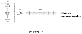
- the lithium iron manganese phosphate precursor and the lithium salt are placed in the precursor storage tank 601 and the lithium salt storage tank 602, respectively, and then the lithium iron manganese phosphate precursor and the lithium salt are transported into the mixing and stirring kettle 603 according to a stoichiometric ratio for mixing and stirring. After that, the obtained mixture is transported to the spray dryer 700 for spray drying.
- the dried mixture is transferred to the calcining furnace 800 for calcining under a nitrogen atmosphere to obtain the lithium iron manganese phosphate positive electrode active material.
- the present invention provides a lithium iron manganese phosphate precursor, the average particle size D50 thereof is 10nm to 1 ⁇ m, preferably 10nm to 500nm, more preferably 10nm to 300nm, and still preferably 10nm to 200nm.
- the lithium iron manganese phosphate precursor material prepared by the rotating packed bed has a fine particle size, and the minimum particle size can reach about 10-100nm, which lays the foundation for the subsequent preparation of nanometer-level lithium iron manganese phosphate materials.
- the lithium iron manganese phosphate material with extremely fine particle size is used in the process of blending with the ternary material, the lithium iron manganese phosphate material can fill and wrap the ternary material, without affecting the compaction density of the material pole piece, thereby improving the volumetric energy density of ternary material batteries.
- the lithium iron manganese phosphate fills in the voids of the ternary material.
- the lithium iron manganese phosphate material can provide elastic strain force, which improves the safety performance of the ternary material battery.
- the present invention also provides a lithium iron manganese phosphate, which has a resistivity under 80kg of 10 ⁇ cm-500 ⁇ cm, preferably 10 ⁇ cm-300 ⁇ cm, more preferably 10 ⁇ cm-200 ⁇ cm, still preferably 10 ⁇ cm to 100 ⁇ cm.
- the lithium iron manganese phosphate can be used as a positive electrode active material.
- the resistivity of the lithium iron manganese phosphate material prepared by the invention is extremely low under 80kg, and the minimum can reach about 10 ⁇ cm.
- lithium iron manganese phosphate with low resistivity When the lithium iron manganese phosphate with low resistivity is mixed with the ternary positive electrode material, it not only will not affect the overall resistivity of the material, but also can build more lithium ion channels for the intercalation and deintercalation of lithium ions, which greatly improves the electrochemical properties of blended materials.
- the present invention also provides a positive electrode for lithium secondary battery, and the positive electrode comprises the lithium iron manganese phosphate according to the present invention as a positive electrode active material.
- the positive electrode for lithium secondary battery includes a positive electrode current collector and a positive electrode active material layer formed on the positive electrode current collector, and the positive electrode active material layer comprises the positive electrode active material according to the present invention.
- the present invention also provides a lithium secondary battery comprising the above-mentioned positive electrode.
- the present invention also provides a battery module comprising the lithium secondary battery as a unit cell.
- the lithium secondary battery according to the present invention can be used as a unit cell of a battery module, and the battery module can be applied to a battery pack.
- the battery pack can be used as a power source for at least one of the following medium and large equipment: electric tools; electric vehicles, including pure electric vehicles (EV), hybrid electric vehicles (HEV), and plug-in hybrid electric vehicles (PHEV); or power storage devices.
- electric tools including pure electric vehicles (EV), hybrid electric vehicles (HEV), and plug-in hybrid electric vehicles (PHEV); or power storage devices.
- the lithium iron manganese phosphate precursor was prepared by the following procedure.
- step (1) oxalic acid solution at 2 mol/L was replaced with phosphoric acid solution at 2 mol/L.
- step (2) solid iron manganese phosphate was obtained, which was the lithium iron manganese phosphate precursor.
- Example A1 The same procedure as in Example A1 was adopted, except that in step (5), the homogenizer was replaced with a rotating packed bed (vertical rotating packed bed, Hangzhou Ke-Li Chemical Equipment Co., Ltd., BZ650-3P). Finally, solid iron manganese oxalate was obtained, which was the lithium iron manganese phosphate precursor.
- Example A2 The same procedure as in Example A2 was adopted, except that in step (5), the homogenizer was replaced with a rotating packed bed (vertical rotating packed bed, Hangzhou Ke-Li Chemical Equipment Co., Ltd., BZ650-3P). Finally, solid iron manganese phosphate was obtained, which was the lithium iron manganese phosphate precursor.
- step (2) the rotating packed bed was replaced with a co-precipitation reactor. Finally, iron manganese oxalate was obtained, which was the lithium iron manganese phosphate precursor.
- step (2) the rotating packed bed was replaced with a co-precipitation reactor.
- step (3) solid iron manganese phosphate was obtained, which was the lithium iron manganese phosphate precursor.
- a laser particle size analyzer (OMECLS-POP) was used to test the particle size D10, D50, D90 of the product.
- 2g of the powder to be tested was taken and put in a beaker, then 100mL of pure water and 2mL of dispersing agent was added and put into an ultrasonic oscillator for ultrasonic dispersion for 5 minutes, and then poured into a laser particle size analyzer, where the refractive index of the medium was set to 1.33, and the refractive index of the material was set to 1.741, and D10, D50, and D90 parameters were tested.
- Three sets of data were tested in parallel for each sample and averaged, and the results are shown in Table 1 below.
- lithium manganese iron phosphate precursors were prepared by supergravity technology, and the particle size D50 of the two precursors were both nanometer-level, and the particle size distribution was narrow, showing that the particle size distribution was very uniform.
- Comparative Example 1 and Comparative Example 2 co-precipitation reactor was used to prepare the lithium iron manganese phosphate precursor material, and the particle size D50 of the prepared precursor was 10.12 ⁇ m and 8.43 ⁇ m, which were larger, and the particle size distribution range was wider, showing that the particle size was not uniform.
- Example A1 The iron manganese oxalate in Example A1 was mixed with lithium dihydrogen phosphate in a stoichiometric ratio, and after being spray-dried, it was calcined at 700°C for 15 hours in a rotary furnace under nitrogen protection to obtain a lithium iron manganese phosphate material.
- Example A2 The iron manganese phosphate in Example A2 was mixed with lithium carbonate in a stoichiometric ratio, and then calcined at 700°C for 15 hours in a rotary furnace under nitrogen protection to obtain a lithium iron manganese phosphate material.
- Example A3 The iron manganese oxalate in Example A3 was mixed with lithium dihydrogen phosphate in a stoichiometric ratio, and after being spray dried, it was calcined at 700 °C for 15 hours in a rotary furnace under nitrogen protection to obtain a lithium iron manganese phosphate positive electrode material.
- Example A4 The iron manganese phosphate in Example A4 was mixed with lithium carbonate in a stoichiometric ratio, and then calcined at 700°C for 15 hours in a rotary furnace under nitrogen protection to obtain a lithium iron manganese phosphate material.
- the iron manganese oxalate in Comparative Example A1 was mixed with lithium dihydrogen phosphate in a stoichiometric ratio, and after being spray dried, it was calcined at 700°C for 15 hours in a rotary furnace under nitrogen protection to obtain a lithium iron manganese phosphate material.
- the iron manganese phosphate in Comparative Example A2 was mixed with lithium carbonate in a stoichiometric ratio, and then calcined at 700°C for 15 hours in a rotary furnace under nitrogen protection to obtain a lithium iron manganese phosphate material.
- a resistivity meter (Lattice Electronics SZT-D) was used to test the resistivity of the product. First, take a certain amount of powder to be tested and put it in the silo of the resistivity meter until the silo was filled, adjust the pressure to 40.0kg to test its resistivity under 40kg, and then continue to increase the pressure to 80kg to test its resistivity under 80kg. Three sets of data were tested in parallel for each sample and averaged, and the results are shown in Table 2 below.
- Example B1 155.2 ⁇ cm 123.8 ⁇ cm
- Example B2 183.5 ⁇ cm 144.7 ⁇ cm
- Example B3 46.9 ⁇ cm 31.9 ⁇ cm
- Example B4 97.7 ⁇ cm 69.0 ⁇ cm Comparative Example B1 698.3 ⁇ cm 572.1 ⁇ cm Comparative Example B2 798.4 ⁇ cm 688.8 ⁇ cm
- the lithium iron manganese phosphate materials prepared using the rotating packed bed are fine and uniform in particle size, and have a huge specific surface area, which makes carbon coating easier and more uniform. Therefore, the resistivity of the obtained iron manganese phosphate positive electrode material is significantly lower than that of the lithium iron manganese phosphate material produced by other processes.
- Examples B3 and B4 nanometer-level precursors were prepared using the rotating packed bed, and homogenization before carbon coating was carried out using the rotating packed bed.
- the lithium iron manganese phosphate material produced by this process can not only make the particle size fine and uniform, but also make carbon uniformly coated on the surface of the material. Therefore, the resistivity of the lithium iron manganese phosphate material prepared in Examples B3 and B4 is even lower.
- Comparative Examples B1 and B2 the precursor materials were prepared using the co-precipitation reactor, and a common homogenizer was used for homogenization before carbon coating.
- the particle size D50 of the obtained precursor materials is micron level, the particle size is large, and the surface energy is small, the uniformity after carbon coating is poor. Thick carbon coating is easy to affect the lithium ion conduction, and thin coating is easy to affect the electron conduction, which ultimately affects the overall electrochemical performance of the material.
- the resistivity is relatively high, and the resistivity under 80kg is more than 500 ⁇ cm.
- Electrochemical tests were performed on the lithium iron manganese phosphate material (positive electrode active material) prepared in Example B1. The electrochemical tests were performed in the same way as on a CR2032 coin-type half-cell.
- the CR2032 coin-type half-cell was prepared as follows.
- NMP N-methyl-2-pyrrolidone
- the positive electrode slurry was uniformly coated on the aluminum foil, placed in a vacuum oven, and dried at 120°C for 10 hours, so that all NMP in the positive electrode slurry was volatilized to obtain a positive electrode sheet.
- the positive electrode sheet was cut into 15mm diameter discs, put into a tablet press, and pressed at a pressure of IMPa for 5s.
- the pressed positive electrode sheet was put into a glove box for battery assembly, and the glove box was protected by an argon atmosphere.
- pure lithium sheet was used as a negative electrode sheet; polyethylene was used as a separator; and the solution obtained through dissolving 1mol/L lithium hexafluorophosphate in a mixed solvent of ethylene carbonate and diethyl carbonate having a molar ratio of 1:1 was used as electrolyte solution.
- the positive electrode sheet, the separator, and the negative electrode sheet are pressed together to prepare an electrode assembly, which is then placed in a battery case. After that, the electrolyte was injected into the case to produce a CR2032 coin-type half-cell.
- the electrical performance test of the battery includes cycle performance test and rate performance test.
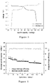
- the cycle performance test and the rate performance test are both measured in a battery tester (Neware, CT-3008) at different charge and discharge rates in the voltage range of 2.5V-4.3V through different times of full-charge and full-discharge. Among them, the test is performed for 8 times at a rate of 0.1C, 8 times at a rate of 0.2C, 20 times at a rate of 0.5C, 50 times at a rate of 1C, and 50 times at a rate of 2C. The results of the measurements are shown in Figures 3 and 4 .
- Figure 3 is the first charge-discharge curve of a battery containing the lithium iron manganese phosphate material (positive electrode active material) prepared in Example B1.
- the battery containing the positive electrode active material prepared in Example B1 has two voltage plateaus during the charging and discharging process, which are the voltage plateaus of manganese and iron respectively. Both voltage plateaus are relatively stable, and voltage value of the manganese voltage plateau is relatively high, so that the median voltage plateau is relatively high.
- the specific capacity of the first charge of the battery can reach 165mAh/h
- the specific capacity of the first discharge is 150mAh/g
- the first charge-discharge efficiency can reach 90.9%, which is significantly higher than that of positive electrodes containing other lithium iron manganese phosphate.
- Figure 4 is a cycle performance curve and a charge-discharge efficiency diagram at different rates of a battery containing the lithium iron manganese phosphate material (positive electrode active material) prepared in Example B1.
- the discharge specific capacity can be maintained at about 150mAh/g at a rate of 0.1C, the discharge specific capacity can be maintained above 140mAh/g at a rate of 1C, and the discharge specific capacity can reach nearly 140mAh/g at a rate of 2C. It can be seen that the rate performance of the battery containing the lithium iron manganese phosphate material of the present invention is better.
Landscapes
- Chemical & Material Sciences (AREA)
- Organic Chemistry (AREA)
- Engineering & Computer Science (AREA)
- Inorganic Chemistry (AREA)
- Chemical Kinetics & Catalysis (AREA)
- Electrochemistry (AREA)
- General Chemical & Material Sciences (AREA)
- Crystallography & Structural Chemistry (AREA)
- Manufacturing & Machinery (AREA)
- Nanotechnology (AREA)
- Materials Engineering (AREA)
- Oil, Petroleum & Natural Gas (AREA)
- Condensed Matter Physics & Semiconductors (AREA)
- General Physics & Mathematics (AREA)
- Physics & Mathematics (AREA)
- Composite Materials (AREA)
- Battery Electrode And Active Subsutance (AREA)
- Organic Low-Molecular-Weight Compounds And Preparation Thereof (AREA)
Applications Claiming Priority (2)
| Application Number | Priority Date | Filing Date | Title |
|---|---|---|---|
| CN201911308409.9A CN110980682A (zh) | 2019-12-18 | 2019-12-18 | 制备磷酸锰铁锂前体的方法和制备磷酸锰铁锂的方法 |
| PCT/CN2020/136685 WO2021121241A1 (zh) | 2019-12-18 | 2020-12-16 | 制备磷酸锰铁锂前体的方法和制备磷酸锰铁锂的方法 |
Publications (2)
| Publication Number | Publication Date |
|---|---|
| EP4079685A1 true EP4079685A1 (de) | 2022-10-26 |
| EP4079685A4 EP4079685A4 (de) | 2024-10-23 |
Family
ID=70095449
Family Applications (1)
| Application Number | Title | Priority Date | Filing Date |
|---|---|---|---|
| EP20903373.7A Pending EP4079685A4 (de) | 2019-12-18 | 2020-12-16 | Verfahren zur herstellung eines lithium-eisen-mangan-phosphat-vorläufers und verfahren zur herstellung von lithium-eisen-mangan-phosphat |
Country Status (6)
| Country | Link |
|---|---|
| US (1) | US20230033756A1 (de) |
| EP (1) | EP4079685A4 (de) |
| JP (1) | JP7545477B2 (de) |
| KR (1) | KR20220107046A (de) |
| CN (1) | CN110980682A (de) |
| WO (1) | WO2021121241A1 (de) |
Families Citing this family (28)
| Publication number | Priority date | Publication date | Assignee | Title |
|---|---|---|---|---|
| CN110980682A (zh) * | 2019-12-18 | 2020-04-10 | 江苏力泰锂能科技有限公司 | 制备磷酸锰铁锂前体的方法和制备磷酸锰铁锂的方法 |
| CN113148969B (zh) * | 2021-04-08 | 2022-11-08 | 江苏力泰锂能科技有限公司 | 掺杂的磷酸锰铁锂-碳复合材料及其制备方法 |
| CN113659134A (zh) * | 2021-07-09 | 2021-11-16 | 江苏乐能电池股份有限公司 | 一种使用共结晶法制备纳米级磷酸铁锰锂材料的方法 |
| CN113659133A (zh) * | 2021-07-09 | 2021-11-16 | 江苏乐能电池股份有限公司 | 一种高压实磷酸铁锰锂正极材料的制备方法 |
| CN113582151B (zh) * | 2021-07-28 | 2024-03-22 | 段镇忠 | 一种磷酸铁锰锂正极材料及其制备方法和应用 |
| CN114220967A (zh) * | 2021-11-09 | 2022-03-22 | 厦门厦钨新能源材料股份有限公司 | 橄榄石型磷酸盐活性材料、其制备方法及应用 |
| CN114314551B (zh) * | 2021-12-31 | 2023-03-10 | 江苏贝特瑞纳米科技有限公司 | 一种爆炸法制备高压实磷酸锰铁锂的方法 |
| CN115057426B (zh) * | 2022-06-17 | 2024-02-13 | 德阳川发龙蟒新材料有限公司 | 一种高倍率和高压实的磷酸锰铁锂的制备方法 |
| CN114899394B (zh) * | 2022-06-29 | 2023-12-19 | 蜂巢能源科技股份有限公司 | 一种改性磷酸锰铁锂正极材料及其制备方法和应用 |
| CN117716538B (zh) * | 2022-07-15 | 2026-01-30 | 宁德时代新能源科技股份有限公司 | 连续式反应系统、草酸锰铁前驱体、磷酸锰铁锂、及制备方法和二次电池 |
| CN115196611A (zh) * | 2022-07-26 | 2022-10-18 | 江西赣锋锂电科技股份有限公司 | 一种低成本磷酸铁锂及磷酸锰铁锂制备方法 |
| CN115321507B (zh) * | 2022-08-25 | 2023-07-07 | 广东邦普循环科技有限公司 | 共沉淀制备磷酸锰铁的方法及其应用 |
| CN115224268B (zh) * | 2022-09-02 | 2025-10-03 | 永州昊利新材料科技有限公司 | 一种磷酸锰铁锂正极材料的制备方法 |
| CN115432689A (zh) * | 2022-09-30 | 2022-12-06 | 福建紫金锂元材料科技有限公司 | 一种高性能长寿命磷酸铁锂正极材料的制备方法 |
| CN115676794B (zh) * | 2022-10-24 | 2024-01-09 | 广东邦普循环科技有限公司 | 共沉淀制备磷酸锰铁锂正极材料的方法及其应用 |
| CN115974681B (zh) * | 2022-12-30 | 2025-02-18 | 蜂巢能源科技股份有限公司 | 一种循环制备草酸锰铁的方法 |
| CN116239091B (zh) * | 2023-02-03 | 2025-03-07 | 广东邦普循环科技有限公司 | 一种磷酸锰铁锂的制备方法、磷酸锰铁锂正极材料及应用 |
| WO2024192621A1 (zh) * | 2023-03-20 | 2024-09-26 | 广东邦普循环科技有限公司 | 一种磷酸锰铁锂及制备其的方法与用途 |
| CN116374987B (zh) * | 2023-04-12 | 2025-01-24 | 安徽洁途新能源科技有限公司 | 一种磷酸锰铁锂的制备方法 |
| CN116374986B (zh) * | 2023-04-14 | 2024-08-02 | 河南佰利新能源材料有限公司 | 一种磷酸铁锂正极材料及其制备方法和应用 |
| KR102700820B1 (ko) * | 2023-08-16 | 2024-08-30 | 이경모 | 폴리올 프로세스 및 화염 분무 방사 열 합성 방법을 이용하여 탄소로 코팅된 리튬 망간 철 인산염의 제조방법 |
| CN117023547B (zh) * | 2023-08-28 | 2024-07-09 | 湖北万润新能源科技股份有限公司 | 一种磷酸锰铁锂的制备方法 |
| CN117615993B (zh) * | 2023-09-08 | 2025-07-29 | 广东邦普循环科技有限公司 | 一种磷酸锰铁锂及其制备方法和应用 |
| KR102634957B1 (ko) * | 2023-09-19 | 2024-02-07 | 씨아이테크 주식회사 | 버티컬 필터 프레스 2차 전지용 전구체 세척 장치 및 방법 |
| CN120072812A (zh) * | 2023-11-28 | 2025-05-30 | 江苏时代新能源科技有限公司 | 前驱体材料及其制备方法、正极材料及其制备方法、正极极片、电池及用电装置 |
| CN117509599A (zh) * | 2023-12-25 | 2024-02-06 | 中国振华集团云科电子有限公司 | 一种高纯磷酸钛铝锂固态电介质及其固相制备方法 |
| CN118598108B (zh) * | 2024-08-01 | 2025-05-13 | 新洋丰农业科技股份有限公司 | 一种磷酸铁锰铵和磷酸铁锰锂的制备方法 |
| CN118970157B (zh) * | 2024-08-28 | 2025-09-09 | 上海恩捷新材料科技有限公司 | 一种固态电解质的制造方法 |
Family Cites Families (17)
| Publication number | Priority date | Publication date | Assignee | Title |
|---|---|---|---|---|
| EP2448044B1 (de) * | 2009-06-24 | 2019-02-27 | GS Yuasa International Ltd. | Positives aktives elektrodenmaterial für eine lithiumsekundärbatterie und lithiumsekundärbatterie |
| CN101837966B (zh) * | 2009-10-16 | 2012-06-20 | 清华大学 | 一种纳米磷酸铁的制备方法 |
| JP5429980B2 (ja) * | 2009-11-05 | 2014-02-26 | テイカ株式会社 | 炭素−オリビン型リン酸マンガン鉄リチウム複合体の製造方法、およびリチウムイオン電池用正極材料 |
| KR101973052B1 (ko) * | 2012-08-10 | 2019-04-26 | 삼성에스디아이 주식회사 | 리튬 금속인산화물의 제조방법 |
| KR20140021843A (ko) * | 2012-08-10 | 2014-02-21 | 삼성정밀화학 주식회사 | 나노사이즈 철인산염 입자의 제조 방법 |
| CN103887491B (zh) * | 2012-12-24 | 2016-08-10 | 上海比亚迪有限公司 | 一种锂离子电池正极活性材料LiMnxFe1-xPO4/C的制备方法 |
| CN104752718B (zh) * | 2013-12-27 | 2017-11-21 | 比亚迪股份有限公司 | 一种LiMnxFe1‑xPO4正极活性材料及其制备方法 |
| CN104752719B (zh) * | 2013-12-27 | 2017-10-13 | 比亚迪股份有限公司 | 一种LiMnxFe1‑xPO4正极活性材料及其制备方法 |
| KR102172027B1 (ko) * | 2013-12-30 | 2020-11-02 | 삼성에스디아이 주식회사 | 리튬 전이금속 인산화물의 제조방법 및 그 방법에 의해 제조된 리튬 전이금속 인산화물 |
| CN106252657A (zh) * | 2015-06-04 | 2016-12-21 | 深圳市比克电池有限公司 | 一种锂电池正极材料制备方法 |
| JP7131911B2 (ja) * | 2015-06-26 | 2022-09-06 | エー123 システムズ エルエルシー | 高出力アプリケーション用のナノスケールポア構造のカソードおよび材料合成方法 |
| CN105047922A (zh) * | 2015-07-20 | 2015-11-11 | 合肥国轩高科动力能源股份公司 | 一种碳包覆磷酸锰铁锂正极材料及制备方法 |
| CN106898769A (zh) * | 2015-12-18 | 2017-06-27 | 惠州比亚迪电池有限公司 | 一种磷酸锰铁锂类材料及其制备方法以及电池浆料组合物和正极与锂电池 |
| CN106564967B (zh) * | 2016-10-31 | 2018-06-05 | 安泰科技股份有限公司 | 富锂锰基正极材料前驱体、正极材料及其制备方法 |
| TWI625888B (zh) * | 2017-07-14 | 2018-06-01 | Hcm Co Ltd | 磷酸鋰錳鐵系顆粒、磷酸鋰錳鐵系粉體及其製備方法 |
| CN110323434B (zh) * | 2019-07-11 | 2022-07-22 | 江苏力泰锂能科技有限公司 | 制备磷酸锰铁锂-碳复合材料的方法和磷酸锰铁锂-碳复合材料 |
| CN110980682A (zh) * | 2019-12-18 | 2020-04-10 | 江苏力泰锂能科技有限公司 | 制备磷酸锰铁锂前体的方法和制备磷酸锰铁锂的方法 |
-
2019
- 2019-12-18 CN CN201911308409.9A patent/CN110980682A/zh active Pending
-
2020
- 2020-12-16 WO PCT/CN2020/136685 patent/WO2021121241A1/zh not_active Ceased
- 2020-12-16 JP JP2022538239A patent/JP7545477B2/ja active Active
- 2020-12-16 EP EP20903373.7A patent/EP4079685A4/de active Pending
- 2020-12-16 US US17/757,638 patent/US20230033756A1/en active Pending
- 2020-12-16 KR KR1020227022373A patent/KR20220107046A/ko not_active Withdrawn
Also Published As
| Publication number | Publication date |
|---|---|
| JP7545477B2 (ja) | 2024-09-04 |
| WO2021121241A1 (zh) | 2021-06-24 |
| EP4079685A4 (de) | 2024-10-23 |
| CN110980682A (zh) | 2020-04-10 |
| KR20220107046A (ko) | 2022-08-01 |
| US20230033756A1 (en) | 2023-02-02 |
| JP2023507212A (ja) | 2023-02-21 |
Similar Documents
| Publication | Publication Date | Title |
|---|---|---|
| EP4079685A1 (de) | Verfahren zur herstellung eines lithium-eisen-mangan-phosphat-vorläufers und verfahren zur herstellung von lithium-eisen-mangan-phosphat | |
| Yang et al. | Morphology-controlled solvothermal synthesis of LiFePO 4 as a cathode material for lithium-ion batteries | |
| CN101145611B (zh) | 锂离子电池正极材料磷酸钒锂的制备方法 | |
| Zhao et al. | High performance LiMnPO 4/C prepared by a crystallite size control method | |
| CN113363483A (zh) | 橄榄石结构正极材料及其制备方法与应用、锂离子电池 | |
| CN111916697A (zh) | 无钴正极材料及其制备方法以及锂离子电池正极和锂电池 | |
| Zhu et al. | Improved high-rate performance of Li4Ti5O12/carbon nanotube nanocomposite anode for lithium-ion batteries | |
| CN103098273A (zh) | 锂二次电池的正电极活性材料、其生产方法和包含其的锂二次电池 | |
| CN103545522A (zh) | 锂离子电池正极活性材料的制备方法 | |
| TWI670894B (zh) | 二次電池用正極活性物質及其製造方法 | |
| CN103515578A (zh) | 锂离子电池正极材料的制备方法 | |
| Li et al. | Influence of synthesis method on the performance of the LiFePO4/C cathode material | |
| CN115863561A (zh) | 一种长循环寿命磷酸铁锂复合材料及其制备方法 | |
| Huang et al. | Facile synthesis of cookies-shaped LiV3O8 cathode materials with good cycling performance for lithium-ion batteries | |
| CN117894960A (zh) | 一种磷酸锰铁锂复合材料及其制备方法 | |
| Zheng et al. | Comparative investigation of microporous and nanosheet LiVOPO 4 as cathode materials for lithium-ion batteries | |
| Zhang et al. | Co-hydrothermal synthesis of LiMn23/24Mg1/24PO4· LiAlO2/C nano-hybrid cathode material with enhanced electrochemical performance for lithium-ion batteries | |
| Li et al. | Synthesis of Li 3 V 2 (PO 4) 3/C for use as the cathode material in lithium ion batteries using polyvinylidene fluoride as the source of carbon | |
| Sun et al. | Synthesis of sub-micron LiNi0. 5Mn1. 5O4 with uniform size distribution by oleylamine-assisted solid-state method | |
| TW201508982A (zh) | 聚陰離子系正極活性物質複合體粒子的製造方法及聚陰離子系正極活性物質的前驅物-氧化石墨複合造粒體 | |
| CN105789605B (zh) | 碳包覆的磷酸铁锂及其制备方法和动力锂离子电池 | |
| CN102054978B (zh) | 一种纳米片微球状锂离子电池阴极电极材料的制备方法 | |
| CN116525811A (zh) | 正极材料前驱体混锂浆料、正极材料前驱体混锂颗粒以及制备方法 | |
| CN115579463B (zh) | 石墨烯磷酸铁锂复合材料及其制备方法、极片及二次电池 | |
| Dong et al. | Synthesis and Properties of Cathode Materials xLi2MnO3·(1− x) LiMn1/3Ni1/3Co1/3O2 for Li-Ion Batteries |
Legal Events
| Date | Code | Title | Description |
|---|---|---|---|
| STAA | Information on the status of an ep patent application or granted ep patent |
Free format text: STATUS: THE INTERNATIONAL PUBLICATION HAS BEEN MADE |
|
| PUAI | Public reference made under article 153(3) epc to a published international application that has entered the european phase |
Free format text: ORIGINAL CODE: 0009012 |
|
| STAA | Information on the status of an ep patent application or granted ep patent |
Free format text: STATUS: REQUEST FOR EXAMINATION WAS MADE |
|
| 17P | Request for examination filed |
Effective date: 20220705 |
|
| AK | Designated contracting states |
Kind code of ref document: A1 Designated state(s): AL AT BE BG CH CY CZ DE DK EE ES FI FR GB GR HR HU IE IS IT LI LT LU LV MC MK MT NL NO PL PT RO RS SE SI SK SM TR |
|
| DAV | Request for validation of the european patent (deleted) | ||
| DAX | Request for extension of the european patent (deleted) | ||
| A4 | Supplementary search report drawn up and despatched |
Effective date: 20240924 |
|
| RIC1 | Information provided on ipc code assigned before grant |
Ipc: C07C 51/41 20060101ALI20240918BHEP Ipc: B82Y 30/00 20110101ALI20240918BHEP Ipc: H01M 10/052 20100101ALI20240918BHEP Ipc: H01M 4/58 20100101ALI20240918BHEP Ipc: H01M 4/136 20100101ALI20240918BHEP Ipc: C01B 25/45 20060101AFI20240918BHEP |