EP4077188B1 - Steuervorrichtung zum steuern einer aufzugsanlage in einem inspektionsbetrieb und aufzugsanlage - Google Patents
Steuervorrichtung zum steuern einer aufzugsanlage in einem inspektionsbetrieb und aufzugsanlage Download PDFInfo
- Publication number
- EP4077188B1 EP4077188B1 EP20811681.4A EP20811681A EP4077188B1 EP 4077188 B1 EP4077188 B1 EP 4077188B1 EP 20811681 A EP20811681 A EP 20811681A EP 4077188 B1 EP4077188 B1 EP 4077188B1
- Authority
- EP
- European Patent Office
- Prior art keywords
- contact
- control
- control terminal
- designed
- switching unit
- Prior art date
- Legal status (The legal status is an assumption and is not a legal conclusion. Google has not performed a legal analysis and makes no representation as to the accuracy of the status listed.)
- Active
Links
Images


Classifications
-
- B—PERFORMING OPERATIONS; TRANSPORTING
- B66—HOISTING; LIFTING; HAULING
- B66B—ELEVATORS; ESCALATORS OR MOVING WALKWAYS
- B66B5/00—Applications of checking, fault-correcting, or safety devices in elevators
- B66B5/0087—Devices facilitating maintenance, repair or inspection tasks
-
- B—PERFORMING OPERATIONS; TRANSPORTING
- B66—HOISTING; LIFTING; HAULING
- B66B—ELEVATORS; ESCALATORS OR MOVING WALKWAYS
- B66B5/00—Applications of checking, fault-correcting, or safety devices in elevators
- B66B5/0006—Monitoring devices or performance analysers
- B66B5/0018—Devices monitoring the operating condition of the elevator system
- B66B5/0031—Devices monitoring the operating condition of the elevator system for safety reasons
-
- B—PERFORMING OPERATIONS; TRANSPORTING
- B66—HOISTING; LIFTING; HAULING
- B66B—ELEVATORS; ESCALATORS OR MOVING WALKWAYS
- B66B5/00—Applications of checking, fault-correcting, or safety devices in elevators
- B66B5/0043—Devices enhancing safety during maintenance
- B66B5/005—Safety of maintenance personnel
Definitions
- the present invention relates to a control device for controlling an elevator installation in an inspection operation. Furthermore, the invention relates to an elevator installation with such a control device.
- Elevators such as passenger or freight elevators are usually equipped with a safety circuit.
- a safety circuit typically comprises a series connection of safety-relevant switches, at least one of which can be opened under certain operating conditions, for example when the elevator is put into inspection mode, a fault is detected or a cabin, shaft door, maintenance door or maintenance hatch is opened. If the safety circuit is interrupted, the elevator is brought to a standstill by switching off a drive of the elevator and activating a braking device to brake the elevator.
- the switches monitor, for example, the closing states of elevator doors, i.e. a cabin door and several shaft doors, so that it can be ensured that a car can only be moved when all elevator doors are closed and the associated door switches are therefore activated.
- the safety circuit When the elevator is being inspected, for example for repair or maintenance purposes, the safety circuit is usually interrupted, for example because a corresponding switch in the safety circuit was opened by putting the elevator into inspection mode or a shaft door had to be opened so that a technician could enter an elevator shaft through it.
- open contacts of the safety circuit can be closed via an inspection path.
- the inspection path can be closed via an inspection control with several control buttons. In order to move the elevator in inspection mode, for example, a first control button to enable a travel movement and a second control button to specify a travel direction must be pressed at the same time.
- the safety circuit comprises at least one series circuit of safety-relevant contacts that are closed when the elevator system is operating without problems. At least one of the contacts can be bridged using semiconductor switches, whereby the semiconductor switches can be controlled using at least one processor and monitored for short circuits using at least one monitoring circuit.
- the safety circuit also comprises at least one electromechanical relay circuit with relay contacts connected in series with the contacts of the bridgeable series circuit.
- the relay circuit can be controlled using the processor.
- the bridgeable series circuit can be interrupted using the relay contacts in the event of a short circuit of the semiconductor switches.
- EP 2 033 927 A1 discloses a control device (200) for controlling an elevator installation in an inspection operation according to the prior art.
- the prior art is about safely interrupting the bridging path because the car is moving towards an unsafe state.
- the aim of the invention is to stop a car movement during inspection operation. There is no urgency in this.
- a first aspect of the invention relates to a control device for controlling an elevator system in an inspection mode.
- the elevator system comprises a safety circuit with at least one safety contact that is opened in the inspection mode and an inspection path for bridging the at least one safety contact.
- the control device comprises a first operating element for operating the elevator system in the inspection mode, a second operating element for Operating the elevator system in inspection mode and a first switching unit which has a first contact and a first delay element and is designed to close the first contact in response to actuation of the first operating element and to open it in response to release of the first operating element.
- the first delay element is designed to delay opening of the first contact by a defined first delay time from release of the first operating element.
- control device comprises a second switching unit connected in parallel with the first switching unit, which has a second contact and a second delay element and is designed to close the second contact in response to actuation of the second operating element and to open it in response to release of the second operating element.
- the second delay element is designed to delay opening of the second contact by a defined second delay time from release of the second operating element.
- the first contact and the second contact are connected in series in the inspection path.
- Such a control device makes it possible to activate a braking device of the elevator system at a time staggered to the release of at least one of the two control buttons of the inspection control.
- This delay can be used to stop the elevator system in a controlled manner by regulating a drive of the elevator system before the elevator system is mechanically braked by the braking device.
- This can reduce the load on load-bearing elements of the elevator system. Wear on the brake disks and brake pads of the braking device can also be reduced.
- Another advantage is the increased comfort for the maintenance personnel, especially if the maintenance personnel are on the roof of a car when the elevator system is being moved.
- a safety circuit can be understood as an electric circuit of the elevator system that comprises a series connection of several safety-relevant contacts. These safety contacts can be closed in normal operation, so that the entire safety circuit is closed and thus in particular the car can be moved. Under certain operating conditions, for example in the event of a malfunction or when the elevator system is put into inspection mode, at least one of the safety switches and thus the entire safety circuit can be opened, which shuts down the elevator system. In particular, If the safety circuit is interrupted, an emergency braking of the elevator system can be initiated.
- An inspection path can be understood as a current path parallel to the series connection of the safety contacts.
- the inspection path can have a series connection of at least two switching contacts. Bridging of the safety contacts can be achieved by closing all contacts in the inspection path.
- a control element can generally be understood as a switch that is operated by touching or pressing with a finger or hand and automatically returns to a rest position when the finger or hand is removed or released.
- the control element can be a mechanical button or a sensor key, such as a capacitive key or a reverb key.
- the first control element and the second control element can each be coupled to a programmable elevator control of the elevator system.
- the elevator control can be configured to detect a respective current switching state of the control elements and to control a power converter of the elevator system depending on the switching state.
- the first control element can be a switch for enabling a travel movement of the elevator system and the second control element can be a switch for specifying a direction of the travel movement.
- the first switching unit and the second switching unit can, for example, be of identical design.
- the two switching units can comprise electromechanical and/or electronic components.
- the two switching units can be implemented entirely in hardware, for example in the form of electromechanical relays. This can reduce the amount of testing required before commissioning an elevator system equipped with such a control device.
- the respective contacts of the two switching units can be mechanical contacts or semiconductor contacts.
- the two delay elements can each be an additional capacitor for storing the electrical energy required to actuate the associated contacts.
- the capacitor can be connected to the associated contacts in such a way that when the capacitor is discharged, the associated contacts can no longer be actuated.
- the delay elements can each be a (programmable) hardware or software module coupled to a suitable timer.
- the first delay time and the second delay time can be the same or different.
- a second aspect of the invention relates to an elevator installation which has a safety circuit with at least one safety contact which is open during an inspection operation of the elevator installation, an inspection path for bridging the at least one safety contact and a control device as described above and below.
- the elevator system can have at least one car, a drive for driving the at least one car, a power converter for regulating a power supply of the drive and a braking device that can be activated by interrupting the safety circuit for braking the at least one car.
- the first delay time and the second delay time can each be selected such that the at least one car can be Regulating the power supply to the drive can be stopped before the braking device is activated.
- the elevator control can be configured to control the power converter as an immediate reaction to the release of at least one of the two control elements so that the drive is stopped.
- the respective delay times should, if possible, not be shorter than the time that the power converter at least needs to regulate the drive down to a standstill.
- the delay times can be selected so that the at least one car is not braked to a standstill, but at least to a very low speed before the braking device is activated.
- a braking device can be understood as a mechanical, for example electrically controlled machine brake or a brake on the elevator car.
- the first delay time and the second delay time can each be greater than 10 ms.
- the delay times can also be significantly greater than 10 ms, for example greater than 20 ms, greater than 50 ms, greater than 100 ms, greater than 500 ms, greater than 1 s, greater than 1.5 s and/or up to 2 s.
- control device can further comprise a third switching unit connected in parallel with the first switching unit and the second switching unit.
- the third switching unit can comprise a third contact and a third delay element and can be designed to close the third contact in response to the actuation of the first operating element and/or the second operating element and to open it in response to the release of the first operating element and the second operating element.
- the third delay element can be designed to delay the closing of the third contact by a defined third delay time from the actuation of the first operating element and/or the second operating element.
- the third contact can be connected in series with the first contact and the second contact in the inspection path.
- the inspection path is independent of how small the time interval between the actuation of the first control element and the actuation of the second control element is always closed with a certain delay. If the third delay time is, for example, longer than the time interval between the actuation of the first control element and the actuation of the second control element, the inspection path can remain interrupted for a certain time even though both control elements have already been actuated. In this way, a switch-on delay can be implemented.
- the third switching unit can be designed to prevent closing of at least one of the three contacts in the inspection path in the event of a fault in the third switching unit.
- the first switching unit can have a first control terminal and can be designed to close the first contact when a control signal is present at the first control terminal and to open the first contact when no control signal is present at the first control terminal.
- the first operating element can be designed to connect the first control terminal to a signal source for providing the control signal in an actuated position and to disconnect it from the signal source in a rest position.
- the first delay element can be designed to delay a drop in the control signal at the first control terminal by the first delay time when the first control terminal is disconnected from the signal source.
- a control signal can be understood as a current signal or a voltage signal, for example.
- the signal source can be understood as an electrical energy source in the form of a current source or a voltage source.
- the first control terminal can, for example, be a coil terminal of a relay or a gate or base terminal of a transistor.
- the second switching unit may have a second control terminal and be designed to close the second contact, when a control signal is present at the second control terminal, and to open the second contact when no control signal is present at the second control terminal.
- the second operating element can be designed to connect the second control terminal to a signal source for providing the control signal in an actuated position and to disconnect it from the signal source in a rest position.
- the second delay element can be designed to delay a drop in the control signal at the second control terminal by the second delay time when the second control terminal is disconnected from the signal source.
- the second control terminal can, for example, be a coil terminal of a relay or a gate or base terminal of a transistor.
- the first switching unit can have a fourth contact and can be designed to open the fourth contact when the control signal is present at the first control terminal and to close it when no control signal is present at the first control terminal.
- the second switching unit can have a fifth contact and can be designed to open the fifth contact when the control signal is present at the second control terminal and to close it when no control signal is present at the second control terminal.
- the third switching unit can also have a third control terminal and can be designed to open the third contact when a control signal is present at the third control terminal and to close it when no control signal is present at the third control terminal.
- the third delay element can be designed to delay a drop in the control signal at the third control terminal by the third delay time when the third control terminal is disconnected from a signal source for providing the control signal.
- the third control terminal can be connectable to the signal source via the fourth contact and the fifth contact.
- the fourth contact and the fifth contact can be connected in series.
- the third delay element can comprise a capacitor that can provide electrical energy for actuating the third contact (or further contacts) of the third switching unit.
- the third switching unit can be separated from the signal source by opening the fourth contact or the fifth contact, so that the third switching unit is only supplied with electrical energy via the capacitor.
- the capacitance of the capacitor determines the third delay time.
- the third contact in the inspection path only closes when the capacitor is discharged. In other words, the two operating elements must be held in their respective actuating positions at the same time for at least the duration of the third delay time in order for the inspection path to close.
- the first switching unit can have a sixth contact and can be designed to close the sixth contact when the control signal is present at the first control terminal and to open it when no control signal is present at the first control terminal.
- the third switching unit can have a seventh contact and can be designed to close the seventh contact when the control signal is present at the third control terminal and to open it when no control signal is present at the third control terminal.
- the sixth contact can be connected between the first operating element and the first control terminal.
- the seventh contact can be arranged in a bridging path that bridges the sixth contact.
- the first control connection can only be connected to the signal source via the first control element if the bridging path is closed. This is the case when the seventh contact is closed by the third switching unit. If the seventh contact cannot be closed for any reason, the first contact that can be controlled via the first control connection can no longer be operated, i.e. closed.
- the first contact, the fourth contact and the sixth contact can, for example, be positively guided.
- the first switching unit can assume exactly two switching states. In a first switching state, the first contact and the sixth contact are open while the fourth contact is closed. In a second switching state, the first contact and the sixth contact are closed while the fourth contact is closed.
- the second switching unit may have an eighth contact and be designed to close the eighth contact when the Control signal is present at the second control terminal, and to open when no control signal is present at the second control terminal.
- the third switching unit can have a ninth contact and can be designed to close the ninth contact when the control signal is present at the second control terminal, and to open when no control signal is present at the third control terminal.
- the eighth contact can be connected between the second operating element and the second control terminal.
- the ninth contact can be arranged in a bridging path that bridges the eighth contact.
- the second control connection can only be connected to the signal source via the second control element if the bridging path bridging the eighth contact is closed. This is the case when the ninth contact is closed by the third switching unit. If the ninth contact cannot be closed for any reason, the second contact that can be controlled via the second control connection can no longer be operated, i.e. closed.
- the second contact, the fifth contact and the eighth contact can, for example, be positively guided.
- the second switching unit can assume exactly two switching states. In a first switching state, the second contact and the eighth contact are open while the fifth contact is closed. In a second switching state, the second contact and the eighth contact are closed while the fifth contact is open.
- the third contact, the seventh contact and the ninth contact can be positively guided.
- the third switching unit can assume exactly two switching states. In a first switching state, the third contact is open while the seventh contact and the ninth contact are closed. In a second switching state, the third contact is closed while the seventh contact and the ninth contact are open.
- the first switching unit can be designed as a first electromechanical relay.
- the second switching unit can be designed as a second electromechanical relay.
- the third switching unit can be designed as a third electromechanical relay.
- Such a relay can comprise a coil and an actuator electromagnetically coupled to the coil, for example in the form of a hinged or tension armature, wherein the actuator is attracted when the coil is switched on and is moved back to a rest position, for example by means of spring force, when the coil is switched off.
- the actuator can be mechanically coupled to one or more contacts of the relay. In the event that the relay comprises several contacts, the contacts can be positively guided via the actuator. This can, for example, prevent an opener and a closer of the relay from being closed or opened at the same time. This embodiment makes it possible to achieve a high level of robustness of the control device. In addition, the control device can be implemented with relatively little effort.
- the first delay element can comprise a capacitor that is connected in parallel with a coil of the first relay.
- the second delay element can comprise a capacitor that is connected in parallel with a coil of the second relay.
- the third delay element can comprise a capacitor that is connected in parallel with a coil of the third relay.
- a respective capacitance of the capacitors can be selected depending on the respective delay time to be achieved.
- the control device can be designed to connect the capacitor of the first relay to a power source in response to the actuation of the first control element in order to charge the capacitor, and to disconnect both the capacitor and the coil of the first relay from the power source in response to the release of the first control element. This can ensure that the coil is supplied with electrical energy exclusively via the capacitor as soon as the first control element is released. This can also apply in an analogous manner to the second relay.
- Fig.1 shows, by way of example, an elevator system 100 with a car 102 that can be moved up and down by means of a drive 104.
- the drive 104 is supplied with power via a power converter 106, for example a frequency converter.
- the elevator system 100 also has a braking device 108 that serves to mechanically brake the car 102 to a standstill and to hold it at a standstill in the event of a malfunction or under certain operating conditions that deviate from normal operation.
- the elevator system 100 has an inspection control 110.
- an operator 112 can switch the elevator system 100 to an inspection mode. In doing so, or when opening a shaft door 114 through which the operator 112 gains access to an elevator shaft 116 of the elevator system 100, a safety circuit of the elevator system 100, and thus the power supply of the drive 104, is interrupted. When the safety circuit is interrupted, the braking device 108 is also activated.
- the inspection control 110 comprises a first control element PB1 for enabling a travel movement and a second control element PB2 for specifying a direction of the travel movement, i.e. up or down.
- the first control element PB1 and the second control element PB2 must be held in their respective actuating position by the operator 112 at the same time so that the elevator car 102 moves up or down.
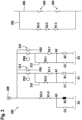
- Fig.2 shows a control device 200 which comprises the two control elements PB1, PB2 Fig.1
- the control device 200 is designed to close an inspection path 202 upon a corresponding actuation of the two control elements PB1, PB2 and to interrupt it upon release of at least one of the two control elements PB1, PB2.
- the inspection path 202 is connected to a series circuit of safety contacts 204 in the manner described in connection with Fig.1
- the safety circuit 206 mentioned above is connected in parallel. In inspection mode, at least one of the safety contacts 204 is open.
- the functioning of the control device 200 is explained in more detail below.
- the control device 200 comprises a first switching unit K1, a second switching unit K2 and a third switching unit K3, which are connected in parallel with one another.
- Each of the three switching units K1, K2, K3 is designed with three contacts, of which two contacts act as normally open contacts and one contact acts as normally closed contacts. These contacts can be designed as mechanical contacts or as semiconductor contacts.
- the following illustrates a switching logic of the control device 200 using the example of three electromechanical relays. However, the switching logic can just as well be implemented with an electronic system, which can be programmable, for example. In order to ensure the safety of the elevator system, the relays or the electronic system can be constructed with suitable electrical and/or electronic components in such a way that they meet a high safety standard, for example the SIL3 standard (Safety Integrity Level).
- the first switching unit K1 has a first coil S 1 and three contacts K1-1, K1-2 and K1-3, which can be opened and closed by means of the first coil S1.
- the contacts K1-1, K1-3 are each designed as make contacts, while the contact K1-2 is designed as break contacts.
- the first switching unit K1 has a first delay element C1, here a first capacitor C1, which is connected in parallel with the first coil S 1.
- the second switching unit K2 has a second coil S2 and three contacts K2-1, K2-2 and K2-3, which can be opened and closed by means of the second coil S2.
- the contacts K2-1, K2-3 are each designed as normally open contacts, while the contact K2-2 is designed as normally closed contacts.
- the second switching unit 210 has a second delay element C2, here a second capacitor C2, which is connected in parallel with the second coil S2.
- the third switching unit K3 has a third coil S3 and three contacts K3-1, K3-2 and K3-3, which can be opened and closed by means of the third coil S3.
- the contacts K3-1, K3-2 are each designed as normally open contacts, while the contact K3-3 is designed as normally closed contacts.
- the third switching unit K3 has a third delay element C3, here a third capacitor C3, which is connected in parallel with the third coil S3.
- K3 and C3 are provided to ensure that K1-3 and K2-3 are only closed when PB 1 and PB2 are pressed within a time period determined by the dimensioning of C3.
- the three delay elements C 1, C2, C3 can also be implemented in other ways, for example as an RC element or diode or as a software module.
- the three contacts K1-3, K2-3, K3-3 are connected in series in the inspection path 202. If all three contacts K1-3, K2-3, K3-3 are closed, the open safety contacts 204 are bridged in the safety circuit 206. The remaining contacts of the control device 200 are interconnected as follows.
- the first coil S1 has a first control connection A1, here a first coil connection A1, which can be connected via the first control element PB 1 to an energy source 208 for providing electrical energy, here a current source.
- the first control element PB 1 is connected in series with the first coil S 1.
- the contact K1-1 is connected between the first control element PB1 and the first coil connection A1.
- the contact K3-2 is connected in parallel with the contact K1-1.
- the contact K3-2 is located in a first bridging path 210, which connects the first coil connection A1 to a line section connecting the contact K1-1 to the first control element PB1.
- the first capacitor C1 is also connected to the first coil terminal A1, so that the first capacitor C1 is charged when the first coil terminal A1 is connected to the energy source 208, and the first coil S1 is supplied with current for a limited period of time depending on the capacity and state of charge when the first coil terminal A1 is disconnected from the energy source 208.
- the second coil S2 has a second coil connection A2, which can be connected to the energy source 208 via the second control element PB2.
- the second control element PB2 is connected in series with the second coil S2.
- the contact K2-1 is connected between the second control element PB2 and the second coil connection A2.
- the contact K3-1 is connected in parallel with the contact K2-1.
- the contact K3-1 is located in a second bridging path 212, which connects the second coil connection A2 with a contact K2-1 with the second Control element PB2 connects.
- the second capacitor C2 is also connected to the second coil connection A2, so that the second capacitor C2 is charged when the second coil connection A2 is connected to the energy source 208, and the second coil S2 is supplied with current depending on its capacity and state of charge when the second coil connection A2 is disconnected from the energy source 208.
- a third coil connection A3 of the third coil S3 can be connected to the energy source 208 via the two contacts K1-2, K2-2, with the two contacts K1-2, K2-2 being connected in series with one another.
- the third coil connection A3 is thus disconnected from the energy source 208 as soon as one of the two contacts K1-2, K2-2 is opened, and is only supplied with power by the energy source 208 when both contacts K1-2, K2-2 are closed.
- the third capacitor C3 is also connected to the third coil connection A3, so that the third capacitor C3 is charged when the third coil connection A3 is connected to the energy source 208, and the third coil S3 is supplied with power depending on its capacity and state of charge when the third coil connection A3 is disconnected from the energy source 208.
- control device 200 has a first feedback path FB1 with a first feedback contact 214 and a second feedback path FB2 with a second feedback contact 216.
- the two feedback paths FB1, FB2 can be connected, for example, to a programmable elevator control of the elevator system 100.
- the first feedback contact 214 is positively guided with the first control element PB1, so that the first feedback contact 214 is closed as soon as the operator 112 actuates the first control element PB1, and is opened again as soon as the operator 112 releases the first control element PB1.
- the second feedback contact 216 is positively guided in an analogous manner with the second control element PB2.
- the elevator control can be informed directly about the respective current switching state of the two control elements PB1, PB2 and control the power converter 106 accordingly.
- Fig.2 shows the control device 200 in a switched-off state in which the control device 200 is disconnected from the energy source 208, the three capacitors C1, C2, C3 are discharged and the two control elements PB1, PB2 are in a respective rest position. Accordingly, the contacts K1-1, K1-3, K2-1, K2-3, K3-1, K3-2 designed as normally open contacts are open and the contacts K1-2, K2-2, K3-3 designed as normally closed contacts are closed.
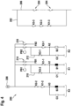
- Fig.3 shows the control device 200 in a switched-on state, in which the control device 200, in contrast to Fig.2 is connected to the energy source 208.
- the third coil connection A3 is supplied with power via the two closed contacts K1-2, K2-2, so that the third capacitor C3 is charged and the third coil S3 is attracted.
- the contact K3-1 in the first bridging path 210 and the contact K3-2 in the second bridging path 212 are closed, while the contact K3-3 in the inspection path 202 is opened.
- the two control elements PB1, PB2 are still in their respective rest positions, so that both the first coil connection A1 and the second coil connection A2 are separated from the energy source 208.
- the first control element PB1 is actuated, a current flows via the closed first bridging path 210 to the first coil connection A1, so that the first capacitor C1 is charged and the first coil S1 is attracted.
- the contact K1-1 between the first coil connection A1 and the first control element PB1 and the contact K1-3 in the inspection path 202 are closed, while the contact K1-2 between the third coil connection A3 and the energy source 208 is opened. This disconnects the third coil connection A3 from the energy source 208.
- the power supply to the third coil S3 is maintained for a limited period of time via the now charged third capacitor C3. As long as the third coil S3 is supplied with power, the contact K3-3 in the inspection path 202 also remains open.
- the third switching unit K3 is blocked for any reason so that the contacts K3-1, K3-2, K3-3 remain in the rest position, although a current flows through the third coil S3, the two control connections A1, A2 can no longer be connected to the energy source 208. This ensures that in the event of a If the third switching unit K3 malfunctions, the two switching units K1, K2 remain in their respective rest position despite actuation of the respective control elements PB1, PB2 and thus the inspection path 202 is not closed.
- Fig.5 shows a switching state of the control device 200 when the second control element PB2 is actuated in addition to the first control element PB1.
- a current flows to the second coil connection A2 via the closed second bridging path 212, so that the second capacitor C2 is charged and the second coil S2 is attracted.
- the contact K2-1 between the second coil connection A2 and the second control element PB2 and the contact K2-3 in the inspection path 202 are closed, while the contact K2-2 between the third coil connection A3 and the energy source 208 is opened.
- the third coil S3 is still sufficiently supplied with current via the third capacitor C3, so that the contact K3-3 in the inspection path 202 is still open and the contacts K3-1, K3-2 are still closed.
- the switching arrangement of the control device 200 shown enables the elevator control to be informed directly about the release of the first control element PB 1 or the second control element PB2 via the first feedback path FB1 or the second feedback path FB2, but the safety circuit 206 is opened with a delay due to a reaction time of the first switching unit K1 or the second switching unit K2, wherein the reaction time depends on a capacitance of the first capacitor C1 or the second capacitor C2.
- the elevator control can bring about a controlled stop of the car 102 at an early stage before the braking device 108 is activated in response to the interruption of the safety circuit 206.
- Fig.8 shows an exemplary embodiment of the first switching unit K1 as a relay in the rest position. This makes it clear at a glance which of the contacts function as a normally open contact and which as a normally closed contact. Shown are the first coil S 1, the first capacitor C1 connected in parallel with it, an armature 800 that can be moved electromagnetically between the rest position and an actuated position by means of the coil S1, here an example of a tension rod, and the three contacts K1-1, K1-2, K1-3, each of which is mechanically coupled to the armature 800 and thus positively guided.
- Fig.9 shows schematically an exemplary embodiment of the second switching unit K2 as a relay in the rest position.
- Fig.10 shows schematically an exemplary embodiment of the third switching unit K3 as a relay in the rest position.
- the switching units K2, K3 are each designed analogously to the first switching unit K1.
Landscapes
- Elevator Control (AREA)
- Maintenance And Inspection Apparatuses For Elevators (AREA)
Description
- Die vorliegende Erfindung betrifft eine Steuervorrichtung zum Steuern einer Aufzugsanlage in einem Inspektionsbetrieb. Ferner betrifft die Erfindung eine Aufzugsanlage mit einer solchen Steuervorrichtung.
- Aufzüge wie Personen- oder Lastaufzüge sind in der Regel mit einem Sicherheitskreis ausgestattet. Ein solcher Sicherheitskreis umfasst typischerweise eine Reihenschaltung sicherheitsrelevanter Schalter, von denen mindestens einer unter bestimmten Betriebsbedingungen geöffnet werden kann, beispielswiese wenn der Aufzug in einen Inspektionsmodus versetzt wird, eine Störung erkannt wird oder eine Kabinen-, Schachttür, Wartungstür oder Wartungsklappen geöffnet wird. Bei einem Unterbrechen des Sicherheitskreises wird der Aufzug zum Stehen gebracht, indem ein Antrieb des Aufzugs abgeschaltet wird und eine Bremsvorrichtung zum Bremsen des Aufzugs aktiviert wird. Die Schalter überwachen als Türschalter beispielsweise Schliesszustände von Aufzugstüren, d. h. einer Kabinentür und mehrerer Schachttüren, sodass sichergestellt werden kann, dass ein Fahrkorb nur dann verfahren werden kann, wenn alle Aufzugstüren geschlossen sind und zugeordnete Türschalter somit betätigt sind.
- In einem Inspektionsbetrieb des Aufzugs, etwa zu Reparatur- oder Wartungszwecken, ist der Sicherheitskreis üblicherweise unterbrochen, beispielsweise weil ein entsprechender Schalter im Sicherheitskreis durch Versetzen des Aufzugs in den Inspektionsmodus geöffnet wurde oder eine Schachttür geöffnet werden musste, damit ein Techniker durch diese einen Aufzugsschacht betreten kann. Um den Aufzug dennoch bedienen zu können, können geöffnete Kontakte des Sicherheitskreises über einen Inspektionspfad geschlossen werden. Der Inspektionspfad kann über eine Inspektionssteuerung mit mehreren Bedienknöpfen geschlossen werden. Um den Aufzug im Inspektionsbetrieb zu bewegen, müssen beispielsweise ein erster Bedienknopf zum Freigeben einer Fahrtbewegung und ein zweiter Bedienknopf zum Vorgeben einer Fahrtrichtung gleichzeitig gedrückt werden. Wird einer der Bedienknöpfe losgelassen wird, so wird der Inspektionspfad, und damit der Sicherheitskreis, sofort wieder unterbrochen, was eine sofortige Aktivierung der Bremsvorrichtung und ein relativ abruptes Abbremsen des Aufzugs zur Folge hat. Dadurch können Kräfte entstehen die tragenden Elemente des Aufzugs stark belasten. Durch die Kräfte können Schwingungen entstehen, welche das Wartungspersonal und deren Prozess, wie zum Beispiel das präzise Positionieren der Kabine beinträchtigen. In
EP 2 493 802 B1 wird ein Sicherheitskreis in einer Aufzugsanlage beschrieben. Der Sicherheitskreis umfasst mindestens eine Serienschaltung von sicherheitsrelevanten, bei störungsfreiem Betrieb der Aufzugsanlage geschlossenen Kontakten. Mindestens einer der Kontakte ist mittels Halbleiterschaltern überbrückbar, wobei die Halbleiterschalter mittels mindestens eines Prozessors steuerbar und mittels mindestens eines Überwachungsschaltkreises auf Kurzschluss überwachbar sind. Ferner umfasst der Sicherheitskreis mindestens einen elektromechanischen Relaiskreis mit in Serie mit den Kontakten der überbrückbaren Serienschaltung geschalteten Relaiskontakten. Der Relaiskreis ist mittels des Prozessors steuerbar. Die überbrückbare Serienschaltung ist im Kurzschlussfall der Halbleiterschalter mittels der Relaiskontakte unterbrechbar.EP 2 033 927 A1 offenbart eine Steuervorrichtung (200) zum Steuern einer Aufzugsanlage in einem Inspektionsbetrieb laut dem Stand der Technik. - Es ist eine Aufgabe der Erfindung, ein Bremsverhalten eines Aufzugs beim Öffnen eines Sicherheitskreises des Aufzugs, insbesondere während einer Inspektion, zu verbessern. Im Stand der Technik geht um das sichere Unterbrechung des Überbrückungspfades, weil die Kabine sich auf einen unsicheren Zustand zu bewegt. Das Ziel der Erfindung ist es eine Kabinenbewegung im Inspektionsbetrieb zu beenden. Dabei gibt es keine Dringlichkeit.
- Die genannte Aufgabe wird durch eine Steuervorrichtung und eine Aufzugsanlage gemäss den unabhängigen Ansprüchen gelöst. Vorteilhafte Ausführungsformen sind in den abhängigen Ansprüchen sowie der nachfolgenden Beschreibung definiert.
- Ein erster Aspekt der Erfindung betrifft eine Steuervorrichtung zum Steuern einer Aufzugsanlage in einem Inspektionsbetrieb. Die Aufzugsanlage umfasst einen Sicherheitskreis mit mindestens einem im Inspektionsbetrieb geöffneten Sicherheitskontakt und einen Inspektionspfad zum Überbrücken des mindestens einen Sicherheitskontakts. Die Steuervorrichtung umfasst ein erstes Bedienelement zum Bedienen der Aufzugsanlage im Inspektionsbetrieb, ein zweites Bedienelement zum Bedienen der Aufzugsanlage im Inspektionsbetrieb und eine erste Schalteinheit, die einen ersten Kontakt und ein erstes Verzögerungsglied aufweist und ausgeführt ist, um den ersten Kontakt als Reaktion auf ein Betätigen des ersten Bedienelements zu schliessen und als Reaktion auf ein Loslassen des ersten Bedienelements zu öffnen. Das erste Verzögerungsglied ist ausgeführt, um ein Öffnen des ersten Kontakts um eine definierte erste Verzögerungszeit ab dem Loslassen des ersten Bedienelements zu verzögern. Ferner umfasst die Steuervorrichtung eine mit der ersten Schalteinheit parallel geschaltete zweite Schalteinheit, die einen zweiten Kontakt und ein zweites Verzögerungsglied aufweist und ausgeführt ist, um den zweiten Kontakt als Reaktion auf ein Betätigen des zweiten Bedienelements zu schliessen und als Reaktion auf ein Loslassen des zweiten Bedienelements zu öffnen. Das zweite Verzögerungsglied ist ausgeführt, um ein Öffnen des zweiten Kontakts um eine definierte zweite Verzögerungszeit ab dem Loslassen des zweiten Bedienelements zu verzögern. Dabei sind der erste Kontakt und der zweite Kontakt in dem Inspektionspfad in Reihe geschaltet.
- Eine solche Steuervorrichtung ermöglicht es, eine Bremsvorrichtung der Aufzugsanlage zeitlich versetzt zum Loslassen zumindest eines der beiden Bedienknöpfe der Inspektionssteuerung zu aktivieren. Diese Verzögerung kann genutzt werden, um die Aufzugsanlage durch Regeln eines Antriebs der Aufzugsanlage kontrolliert anzuhalten, bevor die Aufzugsanlage mechanisch durch die Bremsvorrichtung gebremst wird. Dadurch kann eine Belastung tragender Elemente der Aufzugsanlage reduziert werden. Auch kann ein Verschleiss von Bremsscheiben und Bremsbelägen der Bremsvorrichtung reduziert werden. Ein weiterer Vorteil ist der gesteigerte Komfort für das Wartungspersonal, insbesondere wenn sich das Wartungspersonal beim Bewegen der Aufzugsanlage auf einem Kabinendach aufhält.
- Unter einem Sicherheitskreis kann ein Stromkreis der Aufzugsanlage verstanden werden, der eine Reihenschaltung mehrerer sicherheitsrelevanter Kontakte umfasst. Diese Sicherheitskontakte können in einem Normalbetrieb geschlossen sein, sodass der gesamte Sicherheitskreis geschlossen ist und somit insbesondere ein Verlagern des Fahrkorbs zugelassen wird. Unter bestimmten Betriebsbedingungen, beispielsweise in einem Störfall oder wenn die Aufzugsanlage in einen Inspektionsbetrieb versetzt wird, kann zumindest einer der Sicherheitsschalter und damit der gesamte Sicherheitskreis geöffnet werden, wodurch die Aufzugsanlage stillgelegt wird. Insbesondere kann beim Unterbrechen des Sicherheitskreises eine Notbremsung der Aufzugsanlage veranlasst werden.
- Unter einem Inspektionspfad kann ein Strompfad parallel zur Reihenschaltung der Sicherheitskontakte verstanden werden. Der Inspektionspfad kann eine Reihenschaltung von mindestens zwei Schaltkontakten aufweisen. Eine Überbrückung der Sicherheitskontakte kann dadurch erreicht werden, dass alle Kontakte im Inspektionspfad geschlossen werden.
- Unter einem Bedienelement kann im Allgemeinen ein Schalter verstanden werden, der durch Berühren oder Drücken mit einem Finger oder einer Hand betätigt wird und bei Wegnehmen des Fingers oder der Hand oder bei Loslassen selbsttätig in eine Ruhestellung zurückkehrt. Beispielsweise kann das Bedienelement ein mechanischer Taster oder Knopf oder eine Sensortaste, etwa eine kapazitive Taste oder eine Halltaste, sein.
- Das erste Bedienelement und das zweite Bedienelement können jeweils mit einer programmierbaren Aufzugssteuerung der Aufzugsanlage gekoppelt sein. Die Aufzugssteuerung kann konfiguriert sein, um einen jeweiligen aktuellen Schaltzustand der Bedienelemente zu erfassen und je nach Schaltzustand einen Stromrichter der Aufzugsanlage anzusteuern.
- Beispielsweise kann es sich bei dem ersten Bedienelement um einen Schalter zum Freigeben einer Fahrtbewegung der Aufzugsanlage und bei dem zweiten Bedienelement um einen Schalter zum Vorgeben einer Richtung der Fahrtbewegung handeln.
- Die erste Schalteinheit und die zweite Schalteinheit können beispielsweise baugleich ausgeführt sein. Die beiden Schalteinheiten können elektromechanische und/oder elektronische Bauelemente umfassen. Insbesondere können die beiden Schalteinheiten vollständig in Hardware implementiert sein, beispielsweise in Form elektromechanischer Relais. Dadurch kann ein Prüfaufwand vor Inbetriebnahme einer mit einer solchen Steuervorrichtung ausgestatteten Aufzugsanlage verringert werden. Es ist jedoch auch möglich, dass mindestens eine der beiden Schalteinheiten als programmierbares Elektronikmodul, insbesondere als PESSRAL-Modul (PESSRAL = Programmable Electronic System in Safety Related Applications for Lifts; "programmierbares elektronisches System für elektrische Sicherheitseinrichtungen für Aufzüge") oder als Komponente eines solchen Elektronikmoduls ausgeführt ist.
- Die jeweiligen Kontakte der beiden Schalteinheiten können mechanische Kontakte oder Halbleiterkontakte sein.
- Im einfachsten Fall kann es sich bei den beiden Verzögerungsgliedern jeweils um einen zusätzlichen Kondensator zum Speichern einer zum Betätigen der zugehörigen Kontakte erforderlichen elektrischen Energie handeln. Beispielsweise kann der Kondensator derart mit den zugehörigen Kontakten verschaltet sein, dass, wenn der Kondensator entladen ist, auch die zugehörigen Kontakte nicht mehr betätigt werden können. Alternativ kann es sich bei den Verzögerungsgliedern beispielsweise jeweils um ein mit einem geeigneten Zeitgeber gekoppeltes (programmierbares) Hardware- oder Softwaremodul handeln.
- Die erste Verzögerungszeit und die zweite Verzögerungszeit können gleich oder unterschiedlich sein.
- Ein zweiter Aspekt der Erfindung betrifft eine Aufzugsanlage, die einen Sicherheitskreis mit mindestens einem Sicherheitskontakt, der in einem Inspektionsbetrieb der Aufzugsanlage geöffnet ist, einen Inspektionspfad zum Überbrücken des mindestens einen Sicherheitskontakts und eine Steuervorrichtung, wie sie oben und im Folgenden beschrieben wird, aufweist.
- Mögliche Merkmale und Vorteile von Ausführungsformen der Erfindung können unter anderem und ohne die Erfindung einzuschränken als auf nachfolgend beschriebenen Ideen und Erkenntnissen beruhend angesehen werden.
- Gemäss einer Ausführungsform kann die Aufzugsanlage mindestens einen Fahrkorb, einen Antrieb zum Antreiben des mindestens einen Fahrkorbs, einen Stromrichter zum Regeln einer Stromversorgung des Antriebs und eine durch Unterbrechen des Sicherheitskreises aktivierbare Bremsvorrichtung zum Bremsen des mindestens einen Fahrkorbs aufweisen. Dabei können die erste Verzögerungszeit und die zweite Verzögerungszeit jeweils so gewählt sein, dass der mindestens eine Fahrkorb durch Regeln der Stromversorgung des Antriebs angehalten werden kann, bevor die Bremsvorrichtung aktiviert wird.
- Beispielsweise kann die Aufzugssteuerung konfiguriert sein, um den Stromrichter als unmittelbare Reaktion auf das Loslassen zumindest eines der beiden Bedienelemente so anzusteuern, dass der Antrieb angehalten wird. Dementsprechend sollten die jeweiligen Verzögerungszeiten möglichst nicht kürzer sein als eine Zeit, die der Stromrichter mindestens benötigt, um den Antrieb bis zum Stillstand herunterzuregeln. Alternativ können die Verzögerungszeiten so gewählt werden, dass der mindestens eine Fahrkorb nicht bis zum Stillstand, sondern zumindest bis zu einer sehr geringen Geschwindigkeit abgebremst wird, bevor die Bremsvorrichtung aktiviert wird.
- Unter einer Bremsvorrichtung kann eine mechanische, beispielsweise elektrisch ansteuerbare Maschinenbremse oder eine Bremse am Fahrkorb verstanden werden.
- Gemäss einer Ausführungsform können die erste Verzögerungszeit und die zweite Verzögerungszeit jeweils grösser als 10 ms sein. Die Verzögerungszeiten können jeweils auch deutlich grösser als 10 ms sein, beispielsweise grösser als 20 ms, grösser als 50 ms, grösser als 100 ms, grösser als 500ms, görsser als 1s, gröser 1.5s und/oder bis zu 2s sein.
- Gemäss einer Ausführungsform kann die Steuervorrichtung ferner eine mit der ersten Schalteinheit und der zweiten Schalteinheit parallel geschaltete dritte Schalteinheit aufweisen. Die dritte Schalteinheit kann einen dritten Kontakt und ein drittes Verzögerungsglied aufweisen und ausgeführt sein, um den dritten Kontakt als Reaktion auf das Betätigen des ersten Bedienelements und/oder des zweiten Bedienelements zu schliessen und als Reaktion auf das Loslassen des ersten Bedienelements und des zweiten Bedienelements zu öffnen. Das dritte Verzögerungsglied kann ausgeführt sein, um ein Schliessen des dritten Kontakts um eine definierte dritte Verzögerungszeit ab dem Betätigen des ersten Bedienelements und/oder des zweiten Bedienelements zu verzögern. Dabei kann der dritte Kontakt in dem Inspektionspfad mit dem ersten Kontakt und dem zweiten Kontakt in Reihe geschaltet sein.
- Dadurch kann erreicht werden, dass der Inspektionspfad unabhängig davon, wie klein ein zeitlicher Abstand zwischen dem Betätigen des ersten Bedienelements und dem Betätigen des zweiten Bedienelements ist, stets um eine gewisse Zeit verzögert geschlossen wird. Ist die dritte Verzögerungszeit beispielsweise länger als der zeitliche Abstand zwischen dem Betätigen des ersten Bedienelements und dem Betätigen des zweiten Bedienelements, so kann der Inspektionspfad noch für eine gewisse Zeit unterbrochen bleiben, obwohl bereits beide Bedienelemente betätigt sind. Somit kann eine Einschaltverzögerung realisiert werden.
- Gemäss einer Ausführungsform kann die dritte Schalteinheit ausgeführt sein, um im Fall einer Störung der dritten Schalteinheit ein Schliessen zumindest eines der drei Kontakte in dem Inspektionspfad zu verhindern.
- Dadurch kann verhindert werden, dass der Inspektionspfad ohne Einschaltverzögerung geschlossen werden kann.
- Gemäss einer Ausführungsform kann die erste Schalteinheit einen ersten Steueranschluss aufweisen und ausgeführt sein, um den ersten Kontakt zu schliessen, wenn ein Steuersignal an dem ersten Steueranschluss anliegt, und den ersten Kontakt zu öffnen, wenn kein Steuersignal an dem ersten Steueranschluss anliegt. Dabei kann das erste Bedienelement ausgeführt sein, um den ersten Steueranschluss in einer Betätigungsstellung mit einer Signalquelle zum Bereitstellen des Steuersignals zu verbinden und in einer Ruhestellung von der Signalquelle zu trennen. Dementsprechend kann das erste Verzögerungsglied ausgeführt sein, um ein Abfallen des Steuersignals an dem ersten Steueranschluss um die erste Verzögerungszeit zu verzögern, wenn der erste Steueranschluss von der Signalquelle getrennt wird.
- Unter einem Steuersignal kann beispielsweise ein Stromsignal oder ein Spannungssignal verstanden werden. Dementsprechend kann die Signalquelle als eine elektrische Energiequelle in Form einer Stromquelle oder Spannungsquelle aufgefasst werden.
- Bei dem ersten Steueranschluss kann es sich beispielsweise um einen Spulenanschluss eines Relais oder einen Gate- oder Basis-Anschluss eines Transistors handeln.
- Gemäss einer Ausführungsform kann die zweite Schalteinheit einen zweiten Steueranschluss aufweisen und ausgeführt sein, um den zweiten Kontakt zu schliessen, wenn ein Steuersignal an dem zweiten Steueranschluss anliegt, und den zweiten Kontakt zu öffnen, wenn kein Steuersignal an dem zweiten Steueranschluss anliegt. Dabei kann das zweite Bedienelement ausgeführt sein, um den zweiten Steueranschluss in einer Betätigungsstellung mit einer Signalquelle zum Bereitstellen des Steuersignals zu verbinden und in einer Ruhestellung von der Signalquelle zu trennen. Dementsprechend kann das zweite Verzögerungsglied ausgeführt sein, um ein Abfallen des Steuersignals an dem zweiten Steueranschluss um die zweite Verzögerungszeit zu verzögern, wenn der zweite Steueranschluss von der Signalquelle getrennt wird.
- Bei dem zweiten Steueranschluss kann es sich beispielsweise um einen Spulenanschluss eines Relais oder einen Gate- oder Basis-Anschluss eines Transistors handeln.
- Gemäss einer Ausführungsform kann die erste Schalteinheit einen vierten Kontakt aufweisen und ausgeführt sein, um den vierten Kontakt zu öffnen, wenn das Steuersignal an dem ersten Steueranschluss anliegt, und zu schliessen, wenn kein Steuersignal an dem ersten Steueranschluss anliegt. Dabei kann die zweite Schalteinheit einen fünften Kontakt aufweisen und ausgeführt sein, um den fünften Kontakt zu öffnen, wenn das Steuersignal an dem zweiten Steueranschluss anliegt, und zu schliessen, wenn kein Steuersignal an dem zweiten Steueranschluss anliegt. Die dritte Schalteinheit kann ferner einen dritten Steueranschluss aufweisen und ausgeführt sein, um den dritten Kontakt zu öffnen, wenn ein Steuersignal an dem dritten Steueranschluss anliegt, und zu schliessen, wenn kein Steuersignal an dem dritten Steueranschluss anliegt. Dementsprechend kann das dritte Verzögerungsglied ausgeführt sein, um ein Abfallen des Steuersignals an dem dritten Steueranschluss um die dritte Verzögerungszeit zu verzögern, wenn der dritte Steueranschluss von einer Signalquelle zum Bereitstellen des Steuersignals getrennt wird. Der dritte Steueranschluss kann über den vierten Kontakt und den fünften Kontakt mit der Signalquelle verbindbar sein. Dabei können der vierte Kontakt und der fünfte Kontakt in Reihe geschaltet sein.
- Beispielsweise kann das dritte Verzögerungsglied einen Kondensator umfassen, der eine elektrische Energie zum Betätigen des dritten Kontakts (oder weiterer Kontakte) der dritten Schalteinheit bereitstellen kann. Dabei kann die dritte Schalteinheit durch Öffnen des vierten Kontakts oder des fünften Kontakts von der Signalquelle getrennt werden, sodass die dritte Schalteinheit nur noch über den Kondensator mit elektrischer Energie versorgt wird. Eine Kapazität des Kondensators bestimmt dabei die dritte Verzögerungszeit. Erst wenn der Kondensator entladen ist, schliesst sich der im Inspektionspfad befindliche dritte Kontakt. Anders ausgedrückt müssen die beiden Bedienelemente mindestens für die Dauer der dritten Verzögerungszeit gleichzeitig in ihrer jeweiligen Betätigungsstellung gehalten werden, damit sich der Inspektionspfad schliesst.
- Gemäss einer Ausführungsform kann die erste Schalteinheit einen sechsten Kontakt aufweisen und ausgeführt sein, um den sechsten Kontakt zu schliessen, wenn das Steuersignal an dem ersten Steueranschluss anliegt, und zu öffnen, wenn kein Steuersignal an dem ersten Steueranschluss anliegt. Ferner kann die dritte Schalteinheit einen siebten Kontakt aufweisen und ausgeführt sein, um den siebten Kontakt zu schliessen, wenn das Steuersignal an dem dritten Steueranschluss anliegt, und zu öffnen, wenn kein Steuersignal an dem dritten Steueranschluss anliegt. Dabei kann der sechste Kontakt zwischen das erste Bedienelement und den ersten Steueranschluss geschaltet sein. Der siebte Kontakt kann in einem den sechsten Kontakt überbrückenden Überbrückungspfad angeordnet sein.
- Anders ausgedrückt kann der erste Steueranschluss nur dann über das erste Bedienelement mit der Signalquelle verbunden werden, wenn der Überbrückungspfad geschlossen ist. Dies ist dann der Fall, wenn der siebte Kontakt durch die dritte Schalteinheit geschlossen wird. Sollte der siebte Kontakt aus irgendeinem Grund nicht geschlossen werden können, so kann auch der über den ersten Steueranschluss ansteuerbare erste Kontakt nicht mehr betätigt, d. h. geschlossen werden.
- Der erste Kontakt, der vierte Kontakt und der sechste Kontakt können beispielsweise zwangsgeführt sein. In diesem Fall kann die erste Schalteinheit genau zwei Schaltzustände einnehmen. In einem ersten Schaltzustand sind der erste Kontakt und der sechste Kontakt geöffnet, während der vierte Kontakt geschlossen ist. In einem zweiten Schaltzustand sind der erste Kontakt und der sechste Kontakt geschlossen, während der vierte Kontakt geschlossen ist.
- Gemäss einer Ausführungsform kann die zweite Schalteinheit einen achten Kontakt aufweisen und ausgeführt sein, um den achten Kontakt zu schliessen, wenn das Steuersignal an dem zweiten Steueranschluss anliegt, und zu öffnen, wenn kein Steuersignal an dem zweiten Steueranschluss anliegt. Die dritte Schalteinheit kann einen neunten Kontakt aufweisen und ausgeführt sein, um den neunten Kontakt zu schliessen, wenn das Steuersignal an dem zweiten Steueranschluss anliegt, und zu öffnen, wenn kein Steuersignal an dem dritten Steueranschluss anliegt. Dabei kann der achte Kontakt zwischen das zweite Bedienelement und den zweiten Steueranschluss geschaltet sein. Der neunte Kontakt kann in einem den achten Kontakt überbrückenden Überbrückungspfad angeordnet sein.
- Anders ausgedrückt kann der zweite Steueranschluss nur dann über das zweite Bedienelement mit der Signalquelle verbunden werden, wenn der den achten Kontakt überbrückende Überbrückungspfad geschlossen ist. Dies ist dann der Fall, wenn der neunte Kontakt durch die dritte Schalteinheit geschlossen wird. Sollte der neunte Kontakt aus irgendeinem Grund nicht geschlossen werden können, so kann auch der über den zweiten Steueranschluss ansteuerbare zweite Kontakt nicht mehr betätigt, d. h. geschlossen werden.
- Der zweite Kontakt, der fünfte Kontakt und der achte Kontakt können beispielsweise zwangsgeführt sein. In diesem Fall kann die zweite Schalteinheit genau zwei Schaltzustände einnehmen. In einem ersten Schaltzustand sind der zweite Kontakt und der achte Kontakt geöffnet, während der fünfte Kontakt geschlossen ist. In einem zweiten Schaltzustand sind der zweite Kontakt und der achte Kontakt geschlossen, während der fünfte Kontakt geöffnet ist.
- Ergänzend oder alternativ können beispielsweise der dritte Kontakt, der siebte Kontakt und der neunte Kontakt zwangsgeführt sein. In diesem Fall kann die dritte Schalteinheit genau zwei Schaltzustände einnehmen. In einem ersten Schaltzustand ist der dritte Kontakt geöffnet, während der siebte Kontakt und der neunte Kontakt geschlossen sind. In einem zweiten Schaltzustand ist der dritte Kontakt geschlossen, während der siebte Kontakt und der neunte Kontakt geöffnet sind.
- Gemäss einer Ausführungsform kann die erste Schalteinheit als ein erstes elektromechanisches Relais ausgeführt sein. Ergänzend oder alternativ kann die zweite Schalteinheit als ein zweites elektromechanisches Relais ausgeführt sein. Ergänzend oder alternativ kann die dritte Schalteinheit als ein drittes elektromechanisches Relais ausgeführt sein.
- Ein solches Relais kann eine Spule und ein mit der Spule elektromagnetisch gekoppeltes Stellglied, etwa in Form eines Klapp- oder Zugankers, umfassen, wobei das Stellglied angezogen wird, wenn die Spule eingeschaltet wird, und, beispielsweise mittels Federkraft, zurück in eine Ruhestellung bewegt wird, wenn die Spule ausgeschaltet wird. Das Stellglied kann mit einem oder mehreren Kontakten des Relais mechanisch gekoppelt sein. Für den Fall, dass das Relais mehrere Kontakte umfasst, können die Kontakte über das Stellglied zwangsgeführt sein. Dadurch kann beispielsweise verhindert werden, dass ein Öffner und ein Schliesser des Relais gleichzeitig geschlossen oder geöffnet sind. Durch diese Ausführungsform kann eine hohe Robustheit der Steuervorrichtung erreicht werden. Zudem kann die Steuervorrichtung dadurch mit verhältnismässig geringem Aufwand realisiert werden.
- Gemäss einer Ausführungsform kann das erste Verzögerungsglied einen Kondensator umfassen, der mit einer Spule des ersten Relais parallel geschaltet ist. Ergänzend oder alternativ kann das zweite Verzögerungsglied einen Kondensator umfassen, der mit einer Spule des zweiten Relais parallel geschaltet ist. Ergänzend oder alternativ kann das dritte Verzögerungsglied einen Kondensator umfassen, der mit einer Spule des dritten Relais parallel geschaltet ist.
- Eine jeweilige Kapazität der Kondensatoren kann abhängig von der jeweils zu erreichenden Verzögerungszeit gewählt sein. Beispielsweise kann die Steuervorrichtung ausgeführt sein, um den Kondensator des ersten Relais als Reaktion auf das Betätigen des ersten Bedienelements mit einer Stromquelle zu verbinden, um den Kondensator zu laden, und als Reaktion auf das Loslassen des ersten Bedienelements sowohl den Kondensator als auch die Spule des ersten Relais von der Stromquelle zu trennen. Somit kann sichergestellt werden, dass die Spule ausschliesslich über den Kondensator mit elektrischer Energie versorgt wird, sobald das erste Bedienelement losgelassen wird. Dies kann in analoger Weise auch für das zweite Relais zutreffen.
- Nachfolgend werden Ausführungsformen der Erfindung unter Bezugnahme auf die beigefügten Zeichnungen beschrieben, wobei weder die Zeichnungen noch die Beschreibung als die Erfindung einschränkend auszulegen sind.
-
Fig. 1 zeigt eine beispielhafte Ausführungsform einer Aufzugsanlage. -
Fig. 2 zeigt eine Steuervorrichtung ausFig. 1 im ausgeschalteten Zustand. -
Fig. 3 zeigt die Steuervorrichtung ausFig. 1 im eingeschalteten Zustand. -
Fig. 4 zeigt die Steuervorrichtung ausFig. 1 bei Betätigung eines ersten Bedienelements. -
Fig. 5 zeigt die Steuervorrichtung ausFig. 1 bei Betätigung eines zweiten Bedienelements. -
Fig. 6 zeigt die Steuervorrichtung ausFig. 1 kurz nach Betätigung des ersten Bedienelements und des zweiten Bedienelements. -
Fig. 7 zeigt die Steuervorrichtung ausFig. 1 beim Loslassen des ersten Bedienelements und des zweiten Bedienelements. -
Fig. 8 zeigt eine beispielhafte Ausführungsform einer ersten Schalteinheit der Steuervorrichtung ausFig. 1 . -
Fig. 9 zeigt eine beispielhafte Ausführungsform einer zweiten Schalteinheit der Steuervorrichtung ausFig. 1 . -
Fig. 10 zeigt eine beispielhafte Ausführungsform einer dritten Schalteinheit der Steuervorrichtung ausFig. 1 . - Die Figuren sind lediglich schematisch und nicht massstabsgetreu. Gleiche Bezugszeichen bezeichnen in den verschiedenen Figuren gleiche oder gleichwirkende Merkmale.
-
Fig. 1 zeigt beispielhaft eine Aufzugsanlage 100 mit einem Fahrkorb 102, der mittels eines Antriebs 104 auf und ab bewegt werden kann. Der Antrieb 104 wird über einen Stromrichter 106, beispielsweise einen Frequenzumrichter, mit Strom versorgt. Ferner weist die Aufzugsanlage 100 eine Bremsvorrichtung 108 auf, die dazu dient, den Fahrkorb 102 im Fall einer Störung oder unter bestimmten, von einem Normalbetrieb abweichenden Betriebsbedingungen mechanisch bis zum Stillstand abzubremsen und im Stillstand zu halten. - Um den Fahrkorb 102 in einem Inspektionsbetrieb der Aufzugsanlage 100 verfahren zu können, weist die Aufzugsanlage 100 eine Inspektionssteuerung 110 auf. Mittels der Inspektionssteuerung 110 kann ein Bediener 112 die Aufzugsanlage 100 in einen Inspektionsbetrieb umschalten. Dabei oder auch beim Öffnen einer Schachttüre 114, durch die der Bediener 112 Zutritt zu einem Aufzugsschacht 116 der Aufzugsanlage 100 erlangt, wird ein Sicherheitskreis der Aufzugsanlage 100, und damit die Stromversorgung des Antriebs 104, unterbrochen. Beim Unterbrechen des Sicherheitskreises wird zusätzlich die Bremsvorrichtung 108 aktiviert.
- Die Inspektionssteuerung 110 umfasst ein erstes Bedienelement PB1 zum Freigeben einer Fahrbewegung und ein zweites Bedienelement PB2 zum Vorgeben einer Richtung der Fahrbewegung, d. h. nach oben oder nach unten. Das erste Bedienelement PB1 und das zweite Bedienelement PB2 müssen vom Bediener 112 gleichzeitig in ihrer jeweiligen Betätigungsstellung gehalten werden, damit der Fahrkorb 102 nach oben oder nach unten fährt.
-
Fig. 2 zeigt eine Steuervorrichtung 200, die die zwei Bedienelemente PB1, PB2 ausFig. 1 umfasst. Die Steuervorrichtung 200 ist ausgeführt, um einen Inspektionspfad 202 bei einer entsprechenden Betätigung der beiden Bedienelemente PB1, PB2 zu schliessen und beim Loslassen mindestens eines der beiden Bedienelemente PB1, PB2 zu unterbrechen. Der Inspektionspfad 202 ist mit einer Reihenschaltung von Sicherheitskontakten 204 in dem im Zusammenhang mitFig. 1 erwähnten Sicherheitskreis 206 parallel geschaltet. Im Inspektionsbetrieb ist mindestens einer der Sicherheitskontakte 204 geöffnet. Die Funktionsweise der Steuervorrichtung 200 wird nachfolgend genauer erklärt. - Die Steuervorrichtung 200 umfasst eine erste Schalteinheit K1, eine zweite Schalteinheit K2 und eine dritte Schalteinheit K3, die miteinander parallel geschaltet sind. Jede der drei Schalteinheiten K1, K2, K3 ist mit drei Kontakten ausgeführt, von denen jeweils zwei Kontakte als Schliesser fungieren und ein Kontakt als Öffner fungiert. Diese Kontakte können als mechanische Kontakte oder als Halbleiterkontakte ausgeführt sein. Im Folgenden wird eine Schaltlogik der Steuervorrichtung 200 am Beispiel dreier elektromechanischer Relais illustriert. Die Schaltlogik kann jedoch genauso gut mit einem elektronischen System, das beispielsweise programmierbar sein kann, umgesetzt werden. Um eine Sicherheit der Aufzugsanlage gewährleisten zu können, können dabei die Relais bzw. das elektronische System derart mit geeigneten elektrischen und/oder elektronischen Bauelementen aufgebaut sein, dass sie einem hohen Sicherheitsstandard, beispielsweise dem SIL3-Standard (Safety Integrity Level), entsprechen.
- Die erste Schalteinheit K1 weist eine erste Spule S 1 und drei Kontakte K1-1, K1-2 und K1-3 auf, die mittels der ersten Spule S1 geöffnet und geschlossen werden können. Die Kontakte K1-1, K1-3 sind jeweils als Schliesser ausgeführt, während der Kontakt K1-2 als Öffner ausgeführt ist. Zusätzlich weist die erste Schalteinheit K1 ein erstes Verzögerungsglied C1 auf, hier einen ersten Kondensator C1, der mit der ersten Spule S 1 parallel geschaltet ist.
- Die zweite Schalteinheit K2 weist eine zweite Spule S2 und drei Kontakte K2-1, K2-2 und K2-3 auf, die mittels der zweiten Spule S2 geöffnet und geschlossen werden können. Die Kontakte K2-1, K2-3 sind jeweils als Schliesser ausgeführt, während der Kontakt K2-2 als Öffner ausgeführt ist. Zusätzlich weist die zweite Schalteinheit 210 ein zweites Verzögerungsglied C2 auf, hier einen zweiten Kondensator C2, der mit der zweiten Spule S2 parallel geschaltet ist.
- Die dritte Schalteinheit K3 weist eine dritte Spule S3 und drei Kontakte K3-1, K3-2 und K3-3 auf, die mittels der dritten Spule S3 geöffnet und geschlossen werden können. Die Kontakte K3-1, K3-2 sind jeweils als Schliesser ausgeführt, während der Kontakt K3-3 als Öffner ausgeführt ist. Zusätzlich weist die dritte Schalteinheit K3 ein drittes Verzögerungsglied C3 auf, hier einen dritten Kondensator C3, der mit der dritten Spule S3 parallel geschaltet ist.
- K3 und C3 sind vorahnden um sicherzustellen, dass K1-3 und K2-3 nur geschlossen werden wenn PB 1 und PB2 innerhalb eines durch die Dimensionierung des C3 bestimmten Zeitraums gedrückt werden.
- Die drei Verzögerungsglieder C 1, C2, C3 können auch auf andere Art und Weise umgesetzt sein, beispielsweise als RC-Glied oder Diode oder als Softwaremodul.
- Die drei Kontakte K1-3, K2-3, K3-3 sind in dem Inspektionspfad 202 in Reihe geschaltet. Sind alle drei Kontakte K1-3, K2-3, K3-3 geschlossen, so werden die geöffneten Sicherheitskontakte 204 im Sicherheitskreis 206 überbrückt. Die übrigen Kontakte der Steuervorrichtung 200 sind wie folgt miteinander verschaltet.
- Die erste Spule S1 weist einen ersten Steueranschluss A1, hier einen ersten Spulenanschluss A1, auf, der über das erste Bedienelement PB 1 mit einer Energiequelle 208 zum Bereitstellen einer elektrischen Energie, hier einer Stromquelle, verbindbar ist. Das erste Bedienelement PB 1 ist mit der ersten Spule S 1 in Reihe geschaltet. Zusätzlich ist zwischen das erste Bedienelement PB1 und den ersten Spulenanschluss A1 der Kontakt K1-1 geschaltet. Der Kontakt K3-2 ist mit dem Kontakt K1-1 parallel geschaltet. Dabei befindet sich der Kontakt K3-2 in einem ersten Überbrückungspfad 210, der den ersten Spulenanschluss A1 mit einem den Kontakt K1-1 mit dem ersten Bedienelement PB1 verbindenden Leitungsabschnitt verbindet. An den ersten Spulenanschluss A1 ist zudem der erste Kondensator C1 angeschlossen, sodass der erste Kondensator C1 zum einen geladen wird, wenn der erste Spulenanschluss A1 mit der Energiequelle 208 verbunden ist, zum anderen die erste Spule S1 je nach Kapazität und Ladezustand für eine begrenzte Dauer mit Strom versorgt, wenn der erste Spulenanschluss A1 von der Energiequelle 208 getrennt ist.
- Analog dazu weist die zweite Spule S2 einen zweiten Spulenanschluss A2 auf, der über das zweite Bedienelement PB2 mit der Energiequelle 208 verbindbar ist. Das zweite Bedienelement PB2 ist mit der zweiten Spule S2 in Reihe geschaltet. Zusätzlich ist zwischen das zweite Bedienelement PB2 und den zweiten Spulenanschluss A2 der Kontakt K2-1 geschaltet. Der Kontakt K3-1 ist mit dem Kontakt K2-1 parallel geschaltet. Dabei befindet sich der Kontakt K3-1 in einem zweiten Überbrückungspfad 212, der den zweiten Spulenanschluss A2 mit einem den Kontakt K2-1 mit dem zweiten Bedienelement PB2 verbindenden Leitungsabschnitt verbindet. An den zweiten Spulenanschluss A2 ist zudem der zweite Kondensator C2 angeschlossen, sodass der zweite Kondensator C2 zum einen geladen wird, wenn der zweite Spulenanschluss A2 mit der Energiequelle 208 verbunden ist, zum anderen die zweite Spule S2 je nach Kapazität und Ladezustand mit Strom versorgt, wenn der zweite Spulenanschluss A2 von der Energiequelle 208 getrennt ist.
- Hingegen ist ein dritter Spulenanschluss A3 der dritten Spule S3 über die beiden Kontakte K1-2, K2-2 mit der Energiequelle 208 verbindbar, wobei die beiden Kontakte K1-2, K2-2 miteinander in Reihe geschaltet sind. Somit wird der dritte Spulenanschluss A3 von der Energiequelle 208 getrennt, sobald einer der beiden Kontakte K1-2, K2-2 geöffnet wird, und nur dann durch die Energiequelle 208 mit Strom versorgt, wenn beide Kontakte K1-2, K2-2 geschlossen sind. An den dritten Spulenanschluss A3 ist zudem der dritte Kondensator C3 angeschlossen, sodass der dritte Kondensator C3 zum einen geladen wird, wenn der dritte Spulenanschluss A3 mit der Energiequelle 208 verbunden ist, zum anderen die dritte Spule S3 je nach Kapazität und Ladezustand mit Strom versorgt, wenn der dritte Spulenanschluss A3 von der Energiequelle 208 getrennt ist.
- Zusätzlich weist die Steuervorrichtung 200 einen ersten Rückmeldungspfad FB1 mit einem ersten Rückmeldungskontakt 214 und einen zweiten Rückmeldungspfad FB2 mit einem zweiten Rückmeldungskontakt 216 auf. Die beiden Rückmeldungspfade FB1, FB2 können beispielsweise mit einer programmierbaren Aufzugssteuerung der Aufzugsanlage 100 verbunden sein. Dabei ist der erste Rückmeldungskontakt 214 mit dem ersten Bedienelement PB1 zwangsgeführt, sodass der erste Rückmeldungskontakt 214 geschlossen wird, sobald der Bediener 112 das erste Bedienelement PB1 betätigt, und wieder geöffnet wird, sobald der Bediener 112 das erste Bedienelement PB 1 wieder loslässt. Der zweite Rückmeldungskontakt 216 ist in analoger Weise mit dem zweiten Bedienelement PB2 zwangsgeführt.
- Durch ein derartiges Schliessen oder Öffnen der beiden Rückmeldungspfade FB1, FB2 kann die Aufzugssteuerung unmittelbar über einen jeweiligen aktuellen Schaltzustand der beiden Bedienelements PB1, PB2 informiert werden und den Stromrichter 106 in entsprechender Weise ansteuern.
-
Fig. 2 zeigt die Steuervorrichtung 200 in einem ausgeschalteten Zustand, in dem die Steuervorrichtung 200 von der Energiequelle 208 getrennt ist, die drei Kondensatoren C1, C2, C3 entladen sind und sich die beiden Bedienelemente PB1, PB2 in einer jeweiligen Ruhestellung befinden. Dementsprechend sind die als Schliesser ausgeführten Kontakte K1-1, K1-3, K2-1, K2-3, K3-1, K3-2 geöffnet und die als Öffner ausgeführten Kontakte K1-2, K2-2, K3-3 geschlossen. -
Fig. 3 zeigt die Steuervorrichtung 200 in einem eingeschalteten Zustand, in dem die Steuervorrichtung 200 im Unterschied zuFig. 2 mit der Energiequelle 208 verbunden ist. Dabei wird der dritte Spulenanschluss A3 über die beiden geschlossenen Kontakte K1-2, K2-2 mit Strom versorgt, sodass der dritte Kondensator C3 geladen wird und die dritte Spule S3 anzieht. Dadurch werden der Kontakt K3-1 im ersten Überbrückungspfad 210 und der Kontakt K3-2 im zweiten Überbrückungspfad 212 geschlossen, während der Kontakt K3-3 im Inspektionspfad 202 geöffnet wird. Die beiden Bedienelemente PB1, PB2 befinden sich hier nach wie vor in ihrer jeweiligen Ruhestellung, sodass sowohl der erste Spulenanschluss A1 als auch der zweite Spulenanschluss A2 von der Energiequelle 208 getrennt sind. - Wird nun, wie in
Fig. 4 gezeigt, das erste Bedienelement PB1 betätigt, so fliesst über den geschlossenen ersten Überbrückungspfad 210 ein Strom zum ersten Spulenanschluss A1, sodass der erste Kondensator C1 geladen wird und die erste Spule S1 anzieht. Dadurch werden der Kontakt K1-1 zwischen dem ersten Spulenanschluss A1 und dem ersten Bedienelement PB1 und der Kontakt K1-3 im Inspektionspfad 202 geschlossen, während der Kontakt K1-2 zwischen dem dritten Spulenanschluss A3 und der Energiequelle 208 geöffnet wird. Damit wird der dritte Spulenanschluss A3 von der Energiequelle 208 getrennt. Über den mittlerweile aufgeladenen dritten Kondensator C3 wird die Stromversorgung der dritten Spule S3 für eine begrenzte Dauer aufrechterhalten. Solange die dritte Spule S3 mit Strom versorgt wird, so lange bleibt auch der im Inspektionspfad 202 befindliche Kontakt K3-3 geöffnet. - Ist beispielsweise die dritte Schalteinheit K3 aus irgendeinem Grund blockiert, sodass die Kontakte K3-1, K3-2, K3-3 in der Ruhestellung bleiben, obwohl ein Strom durch die dritte Spule S3 fliesst, so können auch die beiden Steueranschlüsse A1, A2 nicht mehr mit der Energiequelle 208 verbunden werden. Damit ist sichergestellt, dass bei einer Störung der dritten Schalteinheit K3 die beiden Schalteinheiten K1, K2 trotz Betätigung der jeweiligen Bedienelemente PB1, PB2 in ihrer jeweiligen Ruhestellung verharren und damit der Inspektionspfad 202 nicht geschlossen wird.
-
Fig. 5 zeigt einen Schaltzustand der Steuervorrichtung 200, wenn zusätzlich zum ersten Bedienelement PB1 das zweite Bedienelement PB2 betätigt wird. In diesem Fall fliesst analog zum ersten Schaltelement K1 über den geschlossenen zweiten Überbrückungspfad 212 ein Strom zum zweiten Spulenanschluss A2, sodass der zweite Kondensator C2 geladen wird und die zweite Spule S2 anzieht. Dadurch werden der Kontakt K2-1 zwischen dem zweiten Spulenanschluss A2 und dem zweiten Bedienelement PB2 und der Kontakt K2-3 im Inspektionspfad 202 geschlossen, während der Kontakt K2-2 zwischen dem dritten Spulenanschluss A3 und der Energiequelle 208 geöffnet wird. Zu dem Zeitpunkt, zu dem das zweite Bedienelement PB2 hier betätigt wird, wird die dritte Spule S3 über den dritten Kondensator C3 immer noch ausreichend mit Strom versorgt, sodass der im Inspektionspfad 202 befindliche Kontakt K3-3 nach wie vor geöffnet ist und die Kontakte K3-1, K3-2 nach wie vor geschlossen sind. - Sobald der dritte Kondensator C3 entladen ist, fällt die dritte Spule S3 ab und der Kontakt K3-3, und damit der Inspektionspfad 202, wird geschlossen. Gleichzeitig werden die Kontakte K3-1, K3-2 geöffnet. Dies ist in
Fig. 6 gezeigt. - Werden nun, wie in
Fig. 7 gezeigt, die beiden Bedienelemente PB1, PB2 wieder losgelassen, so werden die beiden Spulenanschlüsse A1, A2 zwar jeweils von der Energiequelle 208 getrennt, jedoch über die jeweiligen Kondensatoren C1, C2 vorübergehend weiter mit Strom versorgt. - Erst wenn die beiden Kondensatoren C1, C2 entladen sind, fallen die beiden Spulen S 1, S2 ab, sodass die Kontakte K1-1, K1-3, K2-1, K2-3 wieder geöffnet werden und die Kontakte K1-2, K2-2 wieder geschlossen werden. Dementsprechend wird jetzt auch der dritte Spulenanschluss A3 wieder mit Strom versorgt, sodass der dritte Kondensator C3 wieder geladen wird und die dritte Spule S3 wieder anzieht. Die Steuervorrichtung 200 befindet sich damit wieder in dem in
Fig. 3 gezeigten Schaltzustand. - Die in den
Figuren 2 bis 7 gezeigte Schaltanordnung der Steuervorrichtung 200 ermöglicht es, dass die Aufzugssteuerung über den ersten Rückmeldungspfad FB1 bzw. den zweiten Rückmeldungspfad FB2 unmittelbar über das Loslassen des ersten Bedienelements PB 1 bzw. des zweiten Bedienelements PB2 informiert wird, jedoch der Sicherheitskreis 206 aufgrund einer Reaktionszeit der ersten Schalteinheit K1 bzw. der zweiten Schalteinheit K2 verzögert geöffnet wird, wobei die Reaktionszeit von einer Kapazität des ersten Kondensators C1 bzw. des zweiten Kondensators C2 abhängt. Somit kann die Aufzugssteuerung durch entsprechendes Ansteuern des Stromrichters 106 frühzeitig ein kontrolliertes Anhalten des Fahrkorbs 102 bewirken, bevor die Bremsvorrichtung 108 als Reaktion auf die Unterbrechung des Sicherheitskreises 206 aktiviert wird. -
Fig. 8 zeigt eine beispielhafte Ausführungsform der ersten Schalteinheit K1 als Relais in der Ruhestellung. Daraus ist auf einen Blick ersichtlich, welche der Kontakte als Schliesser und welche als Öffner fungieren. Dargestellt sind die erste Spule S 1, der damit parallel geschaltete erste Kondensator C1, ein mittels der Spule S1 elektromagnetisch zwischen der Ruhestellung und einer Betätigungsstellung bewegbarer Anker 800, hier beispielhaft ein Zuganker, sowie die drei Kontakte K1-1, K1-2, K1-3, die jeweils mechanisch mit dem Anker 800 gekoppelt und damit zwangsgeführt sind. -
Fig. 9 zeigt schematisch eine beispielhafte Ausführungsform der zweiten Schalteinheit K2 als Relais in der Ruhestellung. -
Fig. 10 zeigt schematisch eine beispielhafte Ausführungsform der dritten Schalteinheit K3 als Relais in der Ruhestellung. - Die Schalteinheiten K2, K3 sind jeweils analog zur ersten Schalteinheit K1 ausgeführt.
Claims (13)
- Steuervorrichtung (200) zum Steuern einer Aufzugsanlage (100) in einem Inspektionsbetrieb, wobei die Aufzugsanlage (100) einen Sicherheitskreis (206) mit mindestens einem im Inspektionsbetrieb geöffneten Sicherheitskontakt (204) und einen Inspektionspfad (202) zum Überbrücken des mindestens einen Sicherheitskontakts (204) aufweist, wobei die Steuervorrichtung (200) aufweist:ein erstes Bedienelement (PB1) zum Bedienen der Aufzugsanlage (100) im Inspektionsbetrieb;ein zweites Bedienelement (PB2) zum Bedienen der Aufzugsanlage (100) im Inspektionsbetrieb;eine erste Schalteinheit (K1), die einen ersten Kontakt (K1-3) und ein erstes Verzögerungsglied (C1) aufweist und ausgeführt ist, um den ersten Kontakt (K1-3) als Reaktion auf ein Betätigen des ersten Bedienelements (PB1) zu schliessen und als Reaktion auf ein Loslassen des ersten Bedienelements (PB1) zu öffnen;wobei das erste Verzögerungsglied (C1) ausgeführt ist, um ein Öffnen des ersten Kontakts (K1-3) um eine definierte erste Verzögerungszeit ab dem Loslassen des ersten Bedienelements (PB1) zu verzögern;eine mit der ersten Schalteinheit (K1) parallel geschaltete zweite Schalteinheit (K2), die einen zweiten Kontakt (K2-3) und ein zweites Verzögerungsglied (C2) aufweist und ausgeführt ist, um den zweiten Kontakt (K2-3) als Reaktion auf ein Betätigen des zweiten Bedienelements (PB2) zu schliessen und als Reaktion auf ein Loslassen des zweiten Bedienelements (PB2) zu öffnen;wobei das zweite Verzögerungsglied (C2) ausgeführt ist, um ein Öffnen des zweiten Kontakts (K2-3) um eine definierte zweite Verzögerungszeit ab dem Loslassen des zweiten Bedienelements (PB2) zu verzögern;wobei der erste Kontakt (K1-3) und der zweite Kontakt (K2-3) in dem Inspektionspfad (202) in Reihe geschaltet sind.
- Steuervorrichtung (200) nach Anspruch 1,wobei die Aufzugsanlage (100) mindestens einen Fahrkorb (102), einen Antrieb (104) zum Antreiben des mindestens einen Fahrkorbs (102), einen Stromrichter (106) zum Regeln einer Stromversorgung des Antriebs (104) und eine durch Unterbrechen des Sicherheitskreises (206) aktivierbare Bremsvorrichtung (108) zum Bremsen des mindestens einen Fahrkorbs (102) aufweist;wobei die erste Verzögerungszeit und die zweite Verzögerungszeit jeweils so gewählt sind, dass der mindestens eine Fahrkorb (102) durch Regeln der Stromversorgung des Antriebs (104) angehalten werden kann, bevor die Bremsvorrichtung (108) aktiviert wird.
- Steuervorrichtung (200) nach einem der vorhergehenden Ansprüche,
wobei die erste Verzögerungszeit und die zweite Verzögerungszeit jeweils grösser als 10 ms sind. - Steuervorrichtung (200) nach einem der vorhergehenden Ansprüche, ferner aufweisend:eine mit der ersten Schalteinheit (K1) und der zweiten Schalteinheit (K2) parallel geschaltete dritte Schalteinheit (K3), die einen dritten Kontakt (K3-3) und ein drittes Verzögerungsglied (C3) aufweist und ausgeführt ist, um den dritten Kontakt (K3-3) als Reaktion auf das Betätigen des ersten Bedienelements (PB1) und/oder des zweiten Bedienelements (PB2) zu schliessen und als Reaktion auf das Loslassen des ersten Bedienelements (PB1) und des zweiten Bedienelements (PB2) zu öffnen;wobei das dritte Verzögerungsglied (C3) ausgeführt ist, um ein Schliessen des dritten Kontakts (K3-3) um eine definierte dritte Verzögerungszeit ab dem Betätigen des ersten Bedienelements (PB1) und/oder des zweiten Bedienelements (PB2) zu verzögern;wobei der dritte Kontakt (K3-3) in dem Inspektionspfad (202) mit dem ersten Kontakt (K1-3) und dem zweiten Kontakt (K2-3) in Reihe geschaltet ist.
- Steuervorrichtung (200) nach Anspruch 4,
wobei die dritte Schalteinheit (K3) ausgeführt ist, um im Fall einer Störung der dritten Schalteinheit (K3) ein Schliessen zumindest eines der drei Kontakte (K1-3, K2-3, K3-3) in dem Inspektionspfad (202) zu verhindern. - Steuervorrichtung (200) nach einem der vorhergehenden Ansprüche,wobei die erste Schalteinheit (K1) einen ersten Steueranschluss (A1) aufweist und ausgeführt ist, um den ersten Kontakt (K1-3) zu schliessen, wenn ein Steuersignal an dem ersten Steueranschluss (A1) anliegt, und den ersten Kontakt (K1-3) zu öffnen, wenn kein Steuersignal an dem ersten Steueranschluss (A1) anliegt;wobei das erste Bedienelement (PB1) ausgeführt ist, um den ersten Steueranschluss (A1) in einer Betätigungsstellung mit einer Signalquelle (208) zum Bereitstellen des Steuersignals zu verbinden und in einer Ruhestellung von der Signalquelle (208) zu trennen;wobei das erste Verzögerungsglied (C1) ausgeführt ist, um ein Abfallen des Steuersignals an dem ersten Steueranschluss (A1) um die erste Verzögerungszeit zu verzögern, wenn der erste Steueranschluss (A1) von der Signalquelle (208) getrennt wird.
- Steuervorrichtung (200) nach einem der vorhergehenden Ansprüche,wobei die zweite Schalteinheit (K2) einen zweiten Steueranschluss (A2) aufweist und ausgeführt ist, um den zweiten Kontakt (K2-3) zu schliessen, wenn ein Steuersignal an dem zweiten Steueranschluss (A2) anliegt, und den zweiten Kontakt (K2-3) zu öffnen, wenn kein Steuersignal an dem zweiten Steueranschluss (A2) anliegt;wobei das zweite Bedienelement (PB2) ausgeführt ist, um den zweiten Steueranschluss (A2) in einer Betätigungsstellung mit einer Signalquelle (208) zum Bereitstellen des Steuersignals zu verbinden und in einer Ruhestellung von der Signalquelle (208) zu trennen;wobei das zweite Verzögerungsglied (C2) ausgeführt ist, um ein Abfallen des Steuersignals an dem zweiten Steueranschluss (A2) um die zweite Verzögerungszeit zu verzögern, wenn der zweite Steueranschluss (A2) von der Signalquelle (208) getrennt wird.
- Steuervorrichtung (200) nach Anspruch 7 in Kombination mit Anspruch 5 und 6 oder in Kombination mit Anspruch 4 und 6,wobei die erste Schalteinheit (K1) einen vierten Kontakt (K1-2) aufweist und ausgeführt ist, um den vierten Kontakt (K1-2) zu öffnen, wenn das Steuersignal an dem ersten Steueranschluss (A1) anliegt, und zu schliessen, wenn kein Steuersignal an dem ersten Steueranschluss (A1) anliegt;wobei die zweite Schalteinheit (K2) einen fünften Kontakt (K2-2) aufweist und ausgeführt ist, um den fünften Kontakt (K2-2) zu öffnen, wenn das Steuersignal an dem zweiten Steueranschluss (A2) anliegt, und zu schliessen, wenn kein Steuersignal an dem zweiten Steueranschluss (A2) anliegt;wobei die dritte Schalteinheit (K3) einen dritten Steueranschluss (A3) aufweist und ausgeführt ist, um den dritten Kontakt (K3-3) zu öffnen, wenn ein Steuersignal an dem dritten Steueranschluss (A3) anliegt, und zu schliessen, wenn kein Steuersignal an dem dritten Steueranschluss (A3) anliegt;wobei das dritte Verzögerungsglied (C3) ausgeführt ist, um ein Abfallen des Steuersignals an dem dritten Steueranschluss (A3) um die dritte Verzögerungszeit zu verzögern, wenn der dritte Steueranschluss (A3) von einer Signalquelle (208) zum Bereitstellen des Steuersignals getrennt wird;wobei der dritte Steueranschluss (A3) über den vierten Kontakt (K1-2) und den fünften Kontakt (K2-2) mit der Signalquelle (208) verbindbar ist;wobei der vierte Kontakt (K1-2) und der fünfte Kontakt (K2-2) in Reihe geschaltet sind.
- Steuervorrichtung (200) nach Anspruch 8,wobei die erste Schalteinheit (K1) einen sechsten Kontakt (K1-1) aufweist und ausgeführt ist, um den sechsten Kontakt (K1-1) zu schliessen, wenn das Steuersignal an dem ersten Steueranschluss (A1) anliegt, und zu öffnen, wenn kein Steuersignal an dem ersten Steueranschluss (A1) anliegt;wobei die dritte Schalteinheit (K3) einen siebten Kontakt (K3-2) aufweist und ausgeführt ist, um den siebten Kontakt (K3-2) zu schliessen, wenn das Steuersignal an dem dritten Steueranschluss (A3) anliegt, und zu öffnen, wenn kein Steuersignal an dem dritten Steueranschluss (A3) anliegt;wobei der sechste Kontakt (K1-1) zwischen das erste Bedienelement (PB1) und den ersten Steueranschluss (A1) geschaltet ist;wobei der siebte Kontakt (K3-2) in einem den sechsten Kontakt (K1-1) überbrückenden Überbrückungspfad (210) angeordnet ist.
- Steuervorrichtung (200) nach Anspruch 8 oder 9,wobei die zweite Schalteinheit (K2) einen achten Kontakt (K2-1) aufweist und ausgeführt ist, um den achten Kontakt (K2-1) zu schliessen, wenn das Steuersignal an dem zweiten Steueranschluss (A2) anliegt, und zu öffnen, wenn kein Steuersignal an dem zweiten Steueranschluss (A2) anliegt;wobei die dritte Schalteinheit (K3) einen neunten Kontakt (K3-1) aufweist und ausgeführt ist, um den neunten Kontakt (K3-1) zu schliessen, wenn das Steuersignal an dem zweiten Steueranschluss (A2) anliegt, und zu öffnen, wenn kein Steuersignal an dem dritten Steueranschluss (A3) anliegt;wobei der achte Kontakt (K2-1) zwischen das zweite Bedienelement (PB2) und den zweiten Steueranschluss (A2) geschaltet ist;wobei der neunte Kontakt (K3-1) in einem den achten Kontakt (K2-1) überbrückenden Überbrückungspfad (212) angeordnet ist.
- Steuervorrichtung (200) nach einem der vorhergehenden Ansprüche,wobei die erste Schalteinheit (K1) als ein erstes elektromechanisches Relais ausgeführt ist; und/oderwobei die zweite Schalteinheit (K2) als ein zweites elektromechanisches Relais ausgeführt ist; und/oderwobei die dritte Schalteinheit (K3) als ein drittes elektromechanisches Relais ausgeführt ist.
- Steuervorrichtung (200) nach Anspruch 11 in Kombination mit einem der Ansprüche 1 bis 10,wobei das erste Verzögerungsglied (C1) einen Kondensator (C1) umfasst, der mit einer Spule (S1) des ersten Relais parallel geschaltet ist; und/oderwobei das zweite Verzögerungsglied (C2) einen Kondensator (C2) umfasst, der mit einer Spule (S2) des zweiten Relais parallel geschaltet ist; und/oderwobei das dritte Verzögerungsglied (C3) einen Kondensator (C3) umfasst, der mit einer Spule (S3) des dritten Relais parallel geschaltet ist.
- Aufzugsanlage (100), aufweisend:einen Sicherheitskreis (206) mit mindestens einem Sicherheitskontakt (204), der in einem Inspektionsbetrieb der Aufzugsanlage (100) geöffnet ist;einen Inspektionspfad (202) zum Überbrücken des mindestens einen Sicherheitskontakts (204); undeine Steuervorrichtung (200) nach einem der vorhergehenden Ansprüche.
Applications Claiming Priority (2)
| Application Number | Priority Date | Filing Date | Title |
|---|---|---|---|
| EP19218216 | 2019-12-19 | ||
| PCT/EP2020/083859 WO2021121920A1 (de) | 2019-12-19 | 2020-11-30 | Steuervorrichtung zum steuern einer aufzugsanlage in einem inspektionsbetrieb und aufzugsanlage |
Publications (2)
| Publication Number | Publication Date |
|---|---|
| EP4077188A1 EP4077188A1 (de) | 2022-10-26 |
| EP4077188B1 true EP4077188B1 (de) | 2024-05-08 |
Family
ID=69410976
Family Applications (1)
| Application Number | Title | Priority Date | Filing Date |
|---|---|---|---|
| EP20811681.4A Active EP4077188B1 (de) | 2019-12-19 | 2020-11-30 | Steuervorrichtung zum steuern einer aufzugsanlage in einem inspektionsbetrieb und aufzugsanlage |
Country Status (5)
| Country | Link |
|---|---|
| US (1) | US20230002192A1 (de) |
| EP (1) | EP4077188B1 (de) |
| CN (1) | CN114867677B (de) |
| BR (1) | BR112022011999A2 (de) |
| WO (1) | WO2021121920A1 (de) |
Families Citing this family (5)
| Publication number | Priority date | Publication date | Assignee | Title |
|---|---|---|---|---|
| US12195302B2 (en) * | 2020-03-31 | 2025-01-14 | Inventio Ag | Safety monitoring device, and method for monitoring the safety of an elevator system |
| CN113753695A (zh) * | 2021-08-23 | 2021-12-07 | 杭州西奥电梯有限公司 | 一种电梯节能方法及节能控制装置 |
| WO2023148266A1 (de) * | 2022-02-04 | 2023-08-10 | Cobianchi Liftteile Ag | Bremsfangvorrichtung |
| WO2023148267A1 (de) * | 2022-02-04 | 2023-08-10 | Cobianchi Liftteile Ag | Bremsfangvorrichtung |
| WO2025209999A1 (de) * | 2024-04-05 | 2025-10-09 | Inventio Ag | Verfahren, computerprogramm und prüfvorrichtung zum überprüfen einer personentransportanlage mittels einer überbrückungsvorrichtung, und verfahren und überbrückungsvorrichtung zum automatischen überbrücken eines sicherheitskontakts einer personentransportanlage |
Family Cites Families (11)
| Publication number | Priority date | Publication date | Assignee | Title |
|---|---|---|---|---|
| US4984659A (en) * | 1988-02-01 | 1991-01-15 | Mitsubishi Denki Kabushiki Kaisha | Elevator control apparatus |
| JPH1179593A (ja) * | 1997-09-16 | 1999-03-23 | Toshiba Corp | エレベータの非常時救出運転装置 |
| US6738243B2 (en) * | 2001-12-07 | 2004-05-18 | Eaton Corporation | Apparatus and method for servicing a distribution bus |
| EP2033927B3 (de) * | 2006-06-30 | 2018-12-19 | Otis Elevator Company | Aufzug mit einem flachen Schacht und/oder einem geringen Kopfraum |
| EP2072450A1 (de) * | 2007-12-21 | 2009-06-24 | Inventio Ag | Schaltung zur Zurücksetzung einer Aufzugssicherheitskette |
| JP4803560B2 (ja) * | 2008-09-11 | 2011-10-26 | 東芝エレベータ株式会社 | エレベータの安全装置 |
| PH12012500716A1 (en) | 2009-10-26 | 2016-08-19 | Inventio Ag | Safety circuit in an elevator system |
| EP2452907A1 (de) * | 2010-11-11 | 2012-05-16 | Inventio AG | Aufzugssicherheitsschaltung |
| JP6215027B2 (ja) * | 2013-12-03 | 2017-10-18 | 株式会社日立製作所 | エレベーターの保守点検用ブレーキ制御装置 |
| CN107108152B (zh) * | 2014-12-11 | 2019-04-12 | 因温特奥股份公司 | 解锁装置、具有解锁装置的电梯设备和用于操作解锁装置的方法 |
| EP3371084A1 (de) * | 2015-11-02 | 2018-09-12 | Inventio AG | Versetztes bremsen eines aufzugs |
-
2020
- 2020-11-30 CN CN202080088274.4A patent/CN114867677B/zh active Active
- 2020-11-30 EP EP20811681.4A patent/EP4077188B1/de active Active
- 2020-11-30 US US17/757,238 patent/US20230002192A1/en active Pending
- 2020-11-30 WO PCT/EP2020/083859 patent/WO2021121920A1/de not_active Ceased
- 2020-11-30 BR BR112022011999A patent/BR112022011999A2/pt unknown
Also Published As
| Publication number | Publication date |
|---|---|
| CN114867677B (zh) | 2025-02-21 |
| WO2021121920A1 (de) | 2021-06-24 |
| US20230002192A1 (en) | 2023-01-05 |
| EP4077188A1 (de) | 2022-10-26 |
| BR112022011999A2 (pt) | 2022-08-30 |
| CN114867677A (zh) | 2022-08-05 |
Similar Documents
| Publication | Publication Date | Title |
|---|---|---|
| EP4077188B1 (de) | Steuervorrichtung zum steuern einer aufzugsanlage in einem inspektionsbetrieb und aufzugsanlage | |
| EP2845072B1 (de) | Schaltgerät | |
| EP3793925B1 (de) | Inspektionssteuerungssystem einer aufzugsanlage sowie verfahren zum umschalten einer aufzugsanlage zwischen einem normal- und einem inspektionsbetrieb | |
| EP1618059A1 (de) | Aufzuganlage sowie verfahren zum steuern einer aufzuganlage | |
| EP3814267B1 (de) | Sicherheitsschaltsystem und verfahren zum umschalten einer aufzugsanlage zwischen einem normal- und einem inspektionsbetriebsmodus | |
| EP3704048B1 (de) | Sicherheitsüberwachungsvorrichtung zum überwachen von sicherheitsrelevanten zuständen in einer personenförderanlage sowie verfahren zum betreiben derselben | |
| EP3080030A1 (de) | Sicherheitskreis für eine aufzugsanlage | |
| EP2415058A1 (de) | Modulare schaltungsanordnung zum schalten elektrischer leistungen sowie ein dazu ausgebildeter adapter | |
| DE10016200B4 (de) | Übergeschwindigkeits-Schaltersystem | |
| DE2804130B2 (de) | Überwachungsvorrichtung für Maschinen mit elektrischer Druckknopfsteuerung | |
| WO2006002725A1 (de) | Vorrichtung zum fehlersicheren abschalten eines elektrischen verbrauchers, insbesondere einer elektrisch engetriebenen maschine. | |
| DE19715013B4 (de) | Schaltung zum Start einer Maschine und Verfahren zur Steuerung eines Starts einer Maschine | |
| DE820902C (de) | Weichenschaltung fuer elektrische Stellwerke mit elektrischen Verschluessen | |
| EP0212147A1 (de) | Evakuiervorrichtung für Aufzüge | |
| DE19826039C2 (de) | Überbrückungsschaltung | |
| EP3613691A1 (de) | Wartungsschalttafel und aufzugsteuerung zum kontrolliert abzubremsenden steuern von verlagerungsbewegungen einer aufzugkabine | |
| DE102010051222B4 (de) | Sicherheitsschaltung für eine Zweihandsteuerung | |
| DE10220349B4 (de) | Verfahren und Vorrichtung zum Verbinden einer Versorgungsgleichspannung mit einer Last und zum Trennen der Versorgungsgleichspannung von der Last | |
| DE907783C (de) | Schaltung fuer elektrische Antriebe von Weichen, Gleissperren und aehnlichen Einrichtungen in elektrischen Stellwerken, insbesondere fuer Gleisbildstellwerke und aehnliche Stellwerke mit elektrischen Verschluessen | |
| DE607345C (de) | Zusatzeinrichtung fuer eine Aufzugssteuerung | |
| DE2658031C2 (de) | Schaltvorrichtung für hydraulische Aufzüge | |
| DE10354591B4 (de) | Aufzuganlage | |
| DE3247369A1 (de) | Schaltungsanordnung fuer die lastbegrenzung und ueberlastsicherung eines hubwerkantriebes | |
| DE1506484C (de) | Notschaltung für einen Aufzug | |
| EP4336537A1 (de) | Relaisvorrichtung und sicherheitsschaltgerät mit mindestens einer relaisvorrichtung |
Legal Events
| Date | Code | Title | Description |
|---|---|---|---|
| STAA | Information on the status of an ep patent application or granted ep patent |
Free format text: STATUS: UNKNOWN |
|
| STAA | Information on the status of an ep patent application or granted ep patent |
Free format text: STATUS: THE INTERNATIONAL PUBLICATION HAS BEEN MADE |
|
| PUAI | Public reference made under article 153(3) epc to a published international application that has entered the european phase |
Free format text: ORIGINAL CODE: 0009012 |
|
| STAA | Information on the status of an ep patent application or granted ep patent |
Free format text: STATUS: REQUEST FOR EXAMINATION WAS MADE |
|
| 17P | Request for examination filed |
Effective date: 20220518 |
|
| AK | Designated contracting states |
Kind code of ref document: A1 Designated state(s): AL AT BE BG CH CY CZ DE DK EE ES FI FR GB GR HR HU IE IS IT LI LT LU LV MC MK MT NL NO PL PT RO RS SE SI SK SM TR |
|
| DAV | Request for validation of the european patent (deleted) | ||
| DAX | Request for extension of the european patent (deleted) | ||
| GRAP | Despatch of communication of intention to grant a patent |
Free format text: ORIGINAL CODE: EPIDOSNIGR1 |
|
| STAA | Information on the status of an ep patent application or granted ep patent |
Free format text: STATUS: GRANT OF PATENT IS INTENDED |
|
| INTG | Intention to grant announced |
Effective date: 20231221 |
|
| GRAS | Grant fee paid |
Free format text: ORIGINAL CODE: EPIDOSNIGR3 |
|
| GRAA | (expected) grant |
Free format text: ORIGINAL CODE: 0009210 |
|
| STAA | Information on the status of an ep patent application or granted ep patent |
Free format text: STATUS: THE PATENT HAS BEEN GRANTED |
|
| AK | Designated contracting states |
Kind code of ref document: B1 Designated state(s): AL AT BE BG CH CY CZ DE DK EE ES FI FR GB GR HR HU IE IS IT LI LT LU LV MC MK MT NL NO PL PT RO RS SE SI SK SM TR |
|
| REG | Reference to a national code |
Ref country code: GB Ref legal event code: FG4D Free format text: NOT ENGLISH |
|
| REG | Reference to a national code |
Ref country code: CH Ref legal event code: EP |
|
| REG | Reference to a national code |
Ref country code: DE Ref legal event code: R096 Ref document number: 502020007959 Country of ref document: DE |
|
| REG | Reference to a national code |
Ref country code: IE Ref legal event code: FG4D Free format text: LANGUAGE OF EP DOCUMENT: GERMAN |
|
| REG | Reference to a national code |
Ref country code: LT Ref legal event code: MG9D |
|
| REG | Reference to a national code |
Ref country code: NL Ref legal event code: MP Effective date: 20240508 |
|
| PG25 | Lapsed in a contracting state [announced via postgrant information from national office to epo] |
Ref country code: IS Free format text: LAPSE BECAUSE OF FAILURE TO SUBMIT A TRANSLATION OF THE DESCRIPTION OR TO PAY THE FEE WITHIN THE PRESCRIBED TIME-LIMIT Effective date: 20240908 |
|
| PG25 | Lapsed in a contracting state [announced via postgrant information from national office to epo] |
Ref country code: BG Free format text: LAPSE BECAUSE OF FAILURE TO SUBMIT A TRANSLATION OF THE DESCRIPTION OR TO PAY THE FEE WITHIN THE PRESCRIBED TIME-LIMIT Effective date: 20240508 |
|
| PG25 | Lapsed in a contracting state [announced via postgrant information from national office to epo] |
Ref country code: FI Free format text: LAPSE BECAUSE OF FAILURE TO SUBMIT A TRANSLATION OF THE DESCRIPTION OR TO PAY THE FEE WITHIN THE PRESCRIBED TIME-LIMIT Effective date: 20240508 Ref country code: HR Free format text: LAPSE BECAUSE OF FAILURE TO SUBMIT A TRANSLATION OF THE DESCRIPTION OR TO PAY THE FEE WITHIN THE PRESCRIBED TIME-LIMIT Effective date: 20240508 |
|
| PG25 | Lapsed in a contracting state [announced via postgrant information from national office to epo] |
Ref country code: GR Free format text: LAPSE BECAUSE OF FAILURE TO SUBMIT A TRANSLATION OF THE DESCRIPTION OR TO PAY THE FEE WITHIN THE PRESCRIBED TIME-LIMIT Effective date: 20240809 |
|
| PG25 | Lapsed in a contracting state [announced via postgrant information from national office to epo] |
Ref country code: PT Free format text: LAPSE BECAUSE OF FAILURE TO SUBMIT A TRANSLATION OF THE DESCRIPTION OR TO PAY THE FEE WITHIN THE PRESCRIBED TIME-LIMIT Effective date: 20240909 |
|
| PG25 | Lapsed in a contracting state [announced via postgrant information from national office to epo] |
Ref country code: NL Free format text: LAPSE BECAUSE OF FAILURE TO SUBMIT A TRANSLATION OF THE DESCRIPTION OR TO PAY THE FEE WITHIN THE PRESCRIBED TIME-LIMIT Effective date: 20240508 |
|
| PG25 | Lapsed in a contracting state [announced via postgrant information from national office to epo] |
Ref country code: ES Free format text: LAPSE BECAUSE OF FAILURE TO SUBMIT A TRANSLATION OF THE DESCRIPTION OR TO PAY THE FEE WITHIN THE PRESCRIBED TIME-LIMIT Effective date: 20240508 |
|
| PG25 | Lapsed in a contracting state [announced via postgrant information from national office to epo] |
Ref country code: PL Free format text: LAPSE BECAUSE OF FAILURE TO SUBMIT A TRANSLATION OF THE DESCRIPTION OR TO PAY THE FEE WITHIN THE PRESCRIBED TIME-LIMIT Effective date: 20240508 |
|
| PG25 | Lapsed in a contracting state [announced via postgrant information from national office to epo] |
Ref country code: LV Free format text: LAPSE BECAUSE OF FAILURE TO SUBMIT A TRANSLATION OF THE DESCRIPTION OR TO PAY THE FEE WITHIN THE PRESCRIBED TIME-LIMIT Effective date: 20240508 |
|
| PG25 | Lapsed in a contracting state [announced via postgrant information from national office to epo] |
Ref country code: PT Free format text: LAPSE BECAUSE OF FAILURE TO SUBMIT A TRANSLATION OF THE DESCRIPTION OR TO PAY THE FEE WITHIN THE PRESCRIBED TIME-LIMIT Effective date: 20240909 Ref country code: PL Free format text: LAPSE BECAUSE OF FAILURE TO SUBMIT A TRANSLATION OF THE DESCRIPTION OR TO PAY THE FEE WITHIN THE PRESCRIBED TIME-LIMIT Effective date: 20240508 Ref country code: NO Free format text: LAPSE BECAUSE OF FAILURE TO SUBMIT A TRANSLATION OF THE DESCRIPTION OR TO PAY THE FEE WITHIN THE PRESCRIBED TIME-LIMIT Effective date: 20240808 Ref country code: NL Free format text: LAPSE BECAUSE OF FAILURE TO SUBMIT A TRANSLATION OF THE DESCRIPTION OR TO PAY THE FEE WITHIN THE PRESCRIBED TIME-LIMIT Effective date: 20240508 Ref country code: LV Free format text: LAPSE BECAUSE OF FAILURE TO SUBMIT A TRANSLATION OF THE DESCRIPTION OR TO PAY THE FEE WITHIN THE PRESCRIBED TIME-LIMIT Effective date: 20240508 Ref country code: IS Free format text: LAPSE BECAUSE OF FAILURE TO SUBMIT A TRANSLATION OF THE DESCRIPTION OR TO PAY THE FEE WITHIN THE PRESCRIBED TIME-LIMIT Effective date: 20240908 Ref country code: HR Free format text: LAPSE BECAUSE OF FAILURE TO SUBMIT A TRANSLATION OF THE DESCRIPTION OR TO PAY THE FEE WITHIN THE PRESCRIBED TIME-LIMIT Effective date: 20240508 Ref country code: GR Free format text: LAPSE BECAUSE OF FAILURE TO SUBMIT A TRANSLATION OF THE DESCRIPTION OR TO PAY THE FEE WITHIN THE PRESCRIBED TIME-LIMIT Effective date: 20240809 Ref country code: FI Free format text: LAPSE BECAUSE OF FAILURE TO SUBMIT A TRANSLATION OF THE DESCRIPTION OR TO PAY THE FEE WITHIN THE PRESCRIBED TIME-LIMIT Effective date: 20240508 Ref country code: ES Free format text: LAPSE BECAUSE OF FAILURE TO SUBMIT A TRANSLATION OF THE DESCRIPTION OR TO PAY THE FEE WITHIN THE PRESCRIBED TIME-LIMIT Effective date: 20240508 Ref country code: BG Free format text: LAPSE BECAUSE OF FAILURE TO SUBMIT A TRANSLATION OF THE DESCRIPTION OR TO PAY THE FEE WITHIN THE PRESCRIBED TIME-LIMIT Effective date: 20240508 Ref country code: RS Free format text: LAPSE BECAUSE OF FAILURE TO SUBMIT A TRANSLATION OF THE DESCRIPTION OR TO PAY THE FEE WITHIN THE PRESCRIBED TIME-LIMIT Effective date: 20240808 |
|
| PGFP | Annual fee paid to national office [announced via postgrant information from national office to epo] |
Ref country code: DE Payment date: 20241128 Year of fee payment: 5 |
|
| PG25 | Lapsed in a contracting state [announced via postgrant information from national office to epo] |
Ref country code: DK Free format text: LAPSE BECAUSE OF FAILURE TO SUBMIT A TRANSLATION OF THE DESCRIPTION OR TO PAY THE FEE WITHIN THE PRESCRIBED TIME-LIMIT Effective date: 20240508 |
|
| PGFP | Annual fee paid to national office [announced via postgrant information from national office to epo] |
Ref country code: GB Payment date: 20241126 Year of fee payment: 5 |
|
| PGFP | Annual fee paid to national office [announced via postgrant information from national office to epo] |
Ref country code: FR Payment date: 20241126 Year of fee payment: 5 |
|
| PG25 | Lapsed in a contracting state [announced via postgrant information from national office to epo] |
Ref country code: EE Free format text: LAPSE BECAUSE OF FAILURE TO SUBMIT A TRANSLATION OF THE DESCRIPTION OR TO PAY THE FEE WITHIN THE PRESCRIBED TIME-LIMIT Effective date: 20240508 |
|
| PG25 | Lapsed in a contracting state [announced via postgrant information from national office to epo] |
Ref country code: CZ Free format text: LAPSE BECAUSE OF FAILURE TO SUBMIT A TRANSLATION OF THE DESCRIPTION OR TO PAY THE FEE WITHIN THE PRESCRIBED TIME-LIMIT Effective date: 20240508 |
|
| PG25 | Lapsed in a contracting state [announced via postgrant information from national office to epo] |
Ref country code: SK Free format text: LAPSE BECAUSE OF FAILURE TO SUBMIT A TRANSLATION OF THE DESCRIPTION OR TO PAY THE FEE WITHIN THE PRESCRIBED TIME-LIMIT Effective date: 20240508 Ref country code: RO Free format text: LAPSE BECAUSE OF FAILURE TO SUBMIT A TRANSLATION OF THE DESCRIPTION OR TO PAY THE FEE WITHIN THE PRESCRIBED TIME-LIMIT Effective date: 20240508 |
|
| PG25 | Lapsed in a contracting state [announced via postgrant information from national office to epo] |
Ref country code: SM Free format text: LAPSE BECAUSE OF FAILURE TO SUBMIT A TRANSLATION OF THE DESCRIPTION OR TO PAY THE FEE WITHIN THE PRESCRIBED TIME-LIMIT Effective date: 20240508 |
|
| PG25 | Lapsed in a contracting state [announced via postgrant information from national office to epo] |
Ref country code: SM Free format text: LAPSE BECAUSE OF FAILURE TO SUBMIT A TRANSLATION OF THE DESCRIPTION OR TO PAY THE FEE WITHIN THE PRESCRIBED TIME-LIMIT Effective date: 20240508 Ref country code: SK Free format text: LAPSE BECAUSE OF FAILURE TO SUBMIT A TRANSLATION OF THE DESCRIPTION OR TO PAY THE FEE WITHIN THE PRESCRIBED TIME-LIMIT Effective date: 20240508 Ref country code: RO Free format text: LAPSE BECAUSE OF FAILURE TO SUBMIT A TRANSLATION OF THE DESCRIPTION OR TO PAY THE FEE WITHIN THE PRESCRIBED TIME-LIMIT Effective date: 20240508 Ref country code: EE Free format text: LAPSE BECAUSE OF FAILURE TO SUBMIT A TRANSLATION OF THE DESCRIPTION OR TO PAY THE FEE WITHIN THE PRESCRIBED TIME-LIMIT Effective date: 20240508 Ref country code: DK Free format text: LAPSE BECAUSE OF FAILURE TO SUBMIT A TRANSLATION OF THE DESCRIPTION OR TO PAY THE FEE WITHIN THE PRESCRIBED TIME-LIMIT Effective date: 20240508 Ref country code: CZ Free format text: LAPSE BECAUSE OF FAILURE TO SUBMIT A TRANSLATION OF THE DESCRIPTION OR TO PAY THE FEE WITHIN THE PRESCRIBED TIME-LIMIT Effective date: 20240508 |
|
| PGFP | Annual fee paid to national office [announced via postgrant information from national office to epo] |
Ref country code: CH Payment date: 20241201 Year of fee payment: 5 |
|
| PG25 | Lapsed in a contracting state [announced via postgrant information from national office to epo] |
Ref country code: IT Free format text: LAPSE BECAUSE OF FAILURE TO SUBMIT A TRANSLATION OF THE DESCRIPTION OR TO PAY THE FEE WITHIN THE PRESCRIBED TIME-LIMIT Effective date: 20240508 |
|
| REG | Reference to a national code |
Ref country code: DE Ref legal event code: R097 Ref document number: 502020007959 Country of ref document: DE |
|
| PLBE | No opposition filed within time limit |
Free format text: ORIGINAL CODE: 0009261 |
|
| STAA | Information on the status of an ep patent application or granted ep patent |
Free format text: STATUS: NO OPPOSITION FILED WITHIN TIME LIMIT |
|
| 26N | No opposition filed |
Effective date: 20250211 |
|
| PG25 | Lapsed in a contracting state [announced via postgrant information from national office to epo] |
Ref country code: SI Free format text: LAPSE BECAUSE OF FAILURE TO SUBMIT A TRANSLATION OF THE DESCRIPTION OR TO PAY THE FEE WITHIN THE PRESCRIBED TIME-LIMIT Effective date: 20240508 |
|
| PG25 | Lapsed in a contracting state [announced via postgrant information from national office to epo] |
Ref country code: MC Free format text: LAPSE BECAUSE OF FAILURE TO SUBMIT A TRANSLATION OF THE DESCRIPTION OR TO PAY THE FEE WITHIN THE PRESCRIBED TIME-LIMIT Effective date: 20240508 |
|
| PG25 | Lapsed in a contracting state [announced via postgrant information from national office to epo] |
Ref country code: LU Free format text: LAPSE BECAUSE OF NON-PAYMENT OF DUE FEES Effective date: 20241130 |
|
| REG | Reference to a national code |
Ref country code: BE Ref legal event code: MM Effective date: 20241130 |
|
| PG25 | Lapsed in a contracting state [announced via postgrant information from national office to epo] |
Ref country code: SE Free format text: LAPSE BECAUSE OF FAILURE TO SUBMIT A TRANSLATION OF THE DESCRIPTION OR TO PAY THE FEE WITHIN THE PRESCRIBED TIME-LIMIT Effective date: 20240508 |
|
| PG25 | Lapsed in a contracting state [announced via postgrant information from national office to epo] |
Ref country code: BE Free format text: LAPSE BECAUSE OF NON-PAYMENT OF DUE FEES Effective date: 20241130 |
|
| PG25 | Lapsed in a contracting state [announced via postgrant information from national office to epo] |
Ref country code: IE Free format text: LAPSE BECAUSE OF NON-PAYMENT OF DUE FEES Effective date: 20241130 |
|
| REG | Reference to a national code |
Ref country code: CH Ref legal event code: U11 Free format text: ST27 STATUS EVENT CODE: U-0-0-U10-U11 (AS PROVIDED BY THE NATIONAL OFFICE) Effective date: 20251201 |