EP4076312B1 - Sensor integrated dressings and systems - Google Patents
Sensor integrated dressings and systems Download PDFInfo
- Publication number
- EP4076312B1 EP4076312B1 EP20841897.0A EP20841897A EP4076312B1 EP 4076312 B1 EP4076312 B1 EP 4076312B1 EP 20841897 A EP20841897 A EP 20841897A EP 4076312 B1 EP4076312 B1 EP 4076312B1
- Authority
- EP
- European Patent Office
- Prior art keywords
- substrate
- perforations
- dressing
- wound
- coating
- Prior art date
- Legal status (The legal status is an assumption and is not a legal conclusion. Google has not performed a legal analysis and makes no representation as to the accuracy of the status listed.)
- Active
Links
Images










Classifications
-
- A—HUMAN NECESSITIES
- A61—MEDICAL OR VETERINARY SCIENCE; HYGIENE
- A61F—FILTERS IMPLANTABLE INTO BLOOD VESSELS; PROSTHESES; DEVICES PROVIDING PATENCY TO, OR PREVENTING COLLAPSING OF, TUBULAR STRUCTURES OF THE BODY, e.g. STENTS; ORTHOPAEDIC, NURSING OR CONTRACEPTIVE DEVICES; FOMENTATION; TREATMENT OR PROTECTION OF EYES OR EARS; BANDAGES, DRESSINGS OR ABSORBENT PADS; FIRST-AID KITS
- A61F13/00—Bandages or dressings; Absorbent pads
- A61F13/00051—Accessories for dressings
-
- A—HUMAN NECESSITIES
- A61—MEDICAL OR VETERINARY SCIENCE; HYGIENE
- A61B—DIAGNOSIS; SURGERY; IDENTIFICATION
- A61B5/00—Measuring for diagnostic purposes; Identification of persons
- A61B5/68—Arrangements of detecting, measuring or recording means, e.g. sensors, in relation to patient
- A61B5/6801—Arrangements of detecting, measuring or recording means, e.g. sensors, in relation to patient specially adapted to be attached to or worn on the body surface
- A61B5/683—Means for maintaining contact with the body
- A61B5/6832—Means for maintaining contact with the body using adhesives
-
- A—HUMAN NECESSITIES
- A61—MEDICAL OR VETERINARY SCIENCE; HYGIENE
- A61B—DIAGNOSIS; SURGERY; IDENTIFICATION
- A61B5/00—Measuring for diagnostic purposes; Identification of persons
- A61B5/05—Detecting, measuring or recording for diagnosis by means of electric currents or magnetic fields; Measuring using microwaves or radio waves
- A61B5/053—Measuring electrical impedance or conductance of a portion of the body
-
- A—HUMAN NECESSITIES
- A61—MEDICAL OR VETERINARY SCIENCE; HYGIENE
- A61B—DIAGNOSIS; SURGERY; IDENTIFICATION
- A61B5/00—Measuring for diagnostic purposes; Identification of persons
- A61B5/44—Detecting, measuring or recording for evaluating the integumentary system, e.g. skin, hair or nails
- A61B5/441—Skin evaluation, e.g. for skin disorder diagnosis
- A61B5/445—Evaluating skin irritation or skin trauma, e.g. rash, eczema, wound, bed sore
-
- A—HUMAN NECESSITIES
- A61—MEDICAL OR VETERINARY SCIENCE; HYGIENE
- A61F—FILTERS IMPLANTABLE INTO BLOOD VESSELS; PROSTHESES; DEVICES PROVIDING PATENCY TO, OR PREVENTING COLLAPSING OF, TUBULAR STRUCTURES OF THE BODY, e.g. STENTS; ORTHOPAEDIC, NURSING OR CONTRACEPTIVE DEVICES; FOMENTATION; TREATMENT OR PROTECTION OF EYES OR EARS; BANDAGES, DRESSINGS OR ABSORBENT PADS; FIRST-AID KITS
- A61F13/00—Bandages or dressings; Absorbent pads
- A61F13/00987—Apparatus or processes for manufacturing non-adhesive dressings or bandages
- A61F13/00991—Apparatus or processes for manufacturing non-adhesive dressings or bandages for treating webs, e.g. for moisturising, coating, impregnating or applying powder
-
- A—HUMAN NECESSITIES
- A61—MEDICAL OR VETERINARY SCIENCE; HYGIENE
- A61F—FILTERS IMPLANTABLE INTO BLOOD VESSELS; PROSTHESES; DEVICES PROVIDING PATENCY TO, OR PREVENTING COLLAPSING OF, TUBULAR STRUCTURES OF THE BODY, e.g. STENTS; ORTHOPAEDIC, NURSING OR CONTRACEPTIVE DEVICES; FOMENTATION; TREATMENT OR PROTECTION OF EYES OR EARS; BANDAGES, DRESSINGS OR ABSORBENT PADS; FIRST-AID KITS
- A61F13/00—Bandages or dressings; Absorbent pads
- A61F13/02—Adhesive bandages or dressings
- A61F13/0276—Apparatus or processes for manufacturing adhesive dressings or bandages
-
- A—HUMAN NECESSITIES
- A61—MEDICAL OR VETERINARY SCIENCE; HYGIENE
- A61F—FILTERS IMPLANTABLE INTO BLOOD VESSELS; PROSTHESES; DEVICES PROVIDING PATENCY TO, OR PREVENTING COLLAPSING OF, TUBULAR STRUCTURES OF THE BODY, e.g. STENTS; ORTHOPAEDIC, NURSING OR CONTRACEPTIVE DEVICES; FOMENTATION; TREATMENT OR PROTECTION OF EYES OR EARS; BANDAGES, DRESSINGS OR ABSORBENT PADS; FIRST-AID KITS
- A61F13/00—Bandages or dressings; Absorbent pads
- A61F13/05—Bandages or dressings; Absorbent pads specially adapted for use with sub-pressure or over-pressure therapy, wound drainage or wound irrigation, e.g. for use with negative-pressure wound therapy [NPWT]
Definitions
- Embodiments of the present disclosure relate to apparatuses, systems, and methods for the monitoring and/or treatment of tissue with sensor integrated or sensor-enabled dressings.
- WO2019076967A2 describes a wound dressing including a substantially stretchable wound contact layer supporting a plurality of electronic components.
- WO2019063488A2 describes a wound dressing supporting one or more sensors and a substantially stretchable wound contact layer.
- WO2019020550A2 describes a method of coating a flexible wound contact layer of a wound dressing with a hydrophobic coating.
- WO2020157103A1 describes a wound dressing including a substantially flexible substrate with a wound facing side supporting a plurality of electronic components.
- WO2020043806A1 describes devices and methods for encapsulating a portion of a wound dressing with a biocompatible coating.
- a wound dressing can comprise a flexible substrate with a first, wound-facing side supporting a plurality of electronic components and a second side opposite the first side, wherein the substrate comprises a plurality of perforations formed though the substrate, and wherein the plurality of perforations comprise walls on an exterior surface of the plurality of perforations, a first stretchable coating applied to the first side of the substrate, and a second stretchable coating applied to second side of the substrate, wherein the walls of the plurality of perforations are at least partially coated with at least one of the coatings.
- the wound dressing of any preceding paragraphs and/or any of the wound dressings disclosed herein can include one or more of the following features.
- the walls of the plurality of perforations can be at least partially uniformly coated.
- the plurality of perforations can be greater than or equal to 0.25 mm in diameter.
- the walls of the plurality of perforations can comprise a plurality of grooves.
- the walls of the plurality of perforations can be at least partially non-uniformly coated.
- the dressing can further comprise a protective layer applied to the second side of the substrate, the protective layer can be configured to be removed to expose the substrate.
- the protective layer can comprise first and second portions separated by a slit, the first portion extending over the second portion to cover the slit.
- the plurality of electronic components can comprise a plurality of sensors configured to obtain measurements of the wound, at least some of the plurality of sensors interconnected by a plurality of electronic connections.
- the first stretchable coating can cover an entire area of the first side of the substrate.
- the second stretchable coating can cover an entire area of the second side of the substrate.
- the first stretchable coating and the second stretchable coating can comprise the same material.
- the walls of the plurality of perforations can be at least partially coated with the second stretchable coating.
- the dressing can further comprise a first non-stretchable coating applied to at least some of the plurality of electronic components.
- the first non-stretchable coating can be applied to at least some of the plurality of electronic components, the first stretchable coating applied over the non-stretchable coating.
- the exterior wall of a perforation of the plurality of perforations can comprise a first diameter and the perforation of the plurality of perforations comprises a second diameter formed after at least one of the coatings is applied to the exterior wall, wherein the second diameter is within the first diameter and smaller than the first diameter.
- kits can include the dressing of any of the preceding paragraphs or any of the dressings disclosed herein and a negative pressure wound therapy device configured to supply negative pressure to the wound covered by the dressing.
- the kit of any preceding paragraph and/or any of the kits disclosed herein can include one or more of the following features.
- the dressing and the negative pressure wound therapy device can be sterile.
- the kit can further comprise a secondary dressing configured to be positioned over the dressing of any of the preceding paragraphs or any of the dressings disclosed herein.
- a method of manufacturing a wound dressing can comprise coating a first, wound-facing side of a flexible substrate with a first coating, the substrate comprising a second side opposite the first side, the first side of the substrate supporting a plurality of electronic components, wherein the first coating is applied to at least some of the plurality of electronic components; perforating the substrate coated with the first coating to create a plurality of perforations through the substrate coated with the first coating, the plurality of perforations comprising walls and the plurality of perforations configured to facilitate passage of fluid through the substrate; and coating the second side of the substrate with a second coating, the second coating applied to the substrate positioned on a surface comprising a plurality of pins that extend through the plurality of perforations, and the second coating applied at least partially to the walls of the plurality of perforations.
- the method of the preceding paragraph and/or any of the methods disclosed herein can include one or more of the following features.
- the plurality of pins are tapered or dome shaped.
- the method can further comprise collecting the second coating that flows down the pins in a gutter.
- Coating the second side of the substrate can comprise applying the second coating uniformly to the walls of the plurality of perforations.
- the walls of the plurality of perforations can comprise grooves.
- Coating the second side of the substrate can comprise applying the second coating non-uniformly to the walls of the plurality of perforations.
- the method can further comprise adhering a protective layer to the substrate, the protective layer can be configured to be removed to expose the substrate.
- the method can further comprise coating the first side with a third coating applied to at least some of the plurality of electronic components, wherein the second coating is applied over the third coating.
- a method of manufacturing a wound dressing can comprise coating a first, wound-facing side of a flexible substrate with a first coating, the substrate comprising a second side opposite the first side, the first side of the substrate supporting a plurality of electronic components, wherein the first coating is applied to at least some of the plurality of electronic components, perforating the substrate coated with the first coating to create a first plurality of perforations through the substrate coated with the first coating, the first plurality of perforations comprising walls and having a first diameter, coating the second side of the substrate with a second coating, the second coating applied to fill the plurality of perforations and covering the walls of the plurality of perforations, and perforating the substrate coated with the first coating and second coating to create a second plurality of perforations through the first plurality of perforations of the substrate coated with the first coating and the second coating, the second plurality of perforations comprising a second diameter and the second plurality of perforations is configured to facilitate passage of fluid through the substrate; wherein the second diameter
- Embodiments disclosed herein relate to apparatuses and methods of at least one of monitoring or treating biological tissue with sensor-enabled substrates.
- the embodiments disclosed herein are not limited to treatment or monitoring of a particular type of tissue or injury, instead the sensor-enabled technologies disclosed herein are broadly applicable to any type of therapy that may benefit from sensor-enabled substrates.
- Some implementations utilize sensors and data collection relied upon by health care providers to make both diagnostic and patient management decisions.
- Certain embodiments disclosed herein relate to the use of sensors mounted on or embedded within substrates configured to be used in the treatment of both intact and damaged human or animal tissue. Such sensors may collect information about the surrounding tissue and transmit such information to a computing device or a caregiver to be utilized in further treatment. In certain implementations, such sensors may be attached to the skin anywhere on the body, including areas for monitoring arthritis, temperature, or other areas that may be prone to problems and require monitoring. Sensors disclosed herein may also incorporate markers, such as radiopaque markers, to indicate the presence of the device, for example prior to performing an MRI or other technique.
- markers such as radiopaque markers
- the sensor embodiments disclosed herein may be used in combination with clothing.
- clothing for use with embodiments of the sensors disclosed herein include shirts, pants, trousers, dresses, undergarments, outer-garments, gloves, shoes, hats, and other suitable garments.
- the sensor embodiments disclosed herein may be welded into or laminated into/onto the particular garments.
- the sensor embodiments may be printed directly onto the garment and/or embedded into the fabric. Breathable and printable materials such as microporous membranes may also be suitable.
- Sensor embodiments disclosed herein may be incorporated into cushioning or bed padding, such as within a hospital bed, to monitor patient characteristics, such as any characteristic disclosed herein.
- a disposable film containing such sensors could be placed over the hospital bedding and removed/replaced as needed.
- the sensor embodiments disclosed herein may incorporate energy harvesting, such that the sensor embodiments are self-sustaining.
- energy may be harvested from thermal energy sources, kinetic energy sources, chemical gradients, or any suitable energy source.
- the sensor embodiments disclosed herein may be utilized in rehabilitation devices and treatments, including sports medicine.
- the sensor embodiments disclosed herein may be used in braces, sleeves, wraps, supports, and other suitable items.
- the sensor embodiments disclosed herein may be incorporated into sporting equipment, such as helmets, sleeves, and/or pads.
- such sensor embodiments may be incorporated into a protective helmet to monitor characteristics such as acceleration, which may be useful in concussion diagnosis.
- the sensor embodiments disclosed herein may be used in coordination with surgical devices, for example, the NAVIO surgical system by Smith & Nephew Inc.
- the sensor embodiments disclosed herein may be in communication with such surgical devices to guide placement of the surgical devices.
- the sensor embodiments disclosed herein may monitor blood flow to or away from the potential surgical site or ensure that there is no blood flow to a surgical site. Further surgical data may be collected to aid in the prevention of scarring and monitor areas away from the impacted area.
- the sensors disclosed herein may be incorporated into a surgical drape to provide information regarding tissue under the drape that may not be immediately visible to the naked eye.
- a sensor embedded flexible drape may have sensors positioned advantageously to provide improved area-focused data collection.
- the sensor embodiments disclosed herein may be incorporated into the border or interior of a drape to create fencing to limit/ control the surgical theater.
- the sensor embodiments disclosed herein may be utilized in cardiovascular monitoring.
- such sensor embodiments may be incorporated into a flexible cardiovascular monitor that may be placed against the skin to monitor characteristics of the cardiovascular system and communicate such information to another device and/or a caregiver.
- a device may monitor pulse rate, oxygenation of the blood, and/or electrical activity of the heart.
- the sensor embodiments disclosed herein may be utilized for neurophysiological applications, such as monitoring electrical activity of neurons.
- the sensor embodiments disclosed herein may be incorporated into implantable devices, such as implantable orthopedic implants, including flexible implants. Such sensor embodiments may be configured to collect information regarding the implant site and transmit this information to an external source. In some cases, an internal source may also provide power for such an implant.
- the sensor embodiments disclosed herein may also be utilized for monitoring biochemical activity on the surface of the skin or below the surface of the skin, such as lactose buildup in muscle or sweat production on the surface of the skin.
- other characteristics may be monitored, such as glucose concentration, urine concentration, tissue pressure, skin temperature, skin surface conductivity, skin surface resistivity, skin hydration, skin maceration, and/or skin ripping.
- Sensor embodiments as disclosed herein may be incorporated into Ear, Nose, and Throat (ENT) applications.
- ENT Throat
- Sensor embodiments as disclosed herein may be utilized to monitor recovery from ENT-related surgery, such as wound monitoring within the sinus passage.
- Sensor embodiments disclosed herein may encompass sensor printing technology with encapsulation, such as encapsulation with a polymer film.
- a polymer film may be constructed using any polymer described herein, such as polyurethane.
- Encapsulation of the sensor embodiments may provide waterproofing of the electronics and protection from local tissue, local fluids, and other sources of potential damage.
- the sensors disclosed herein may be incorporated into an organ protection layer.
- a sensor-embedded organ protection layer may both protect the organ of interest and confirm that the organ protection layer is in position and providing protection.
- a sensor-embedded organ protection layer may be utilized to monitor the underlying organ, such as by monitoring blood flow, oxygenation, and other suitable markers of organ health.
- a sensor-enabled organ protection layer may be used to monitor a transplanted organ, such as by monitoring the fat and muscle content of the organ.
- sensor-enabled organ protection layers may be used to monitor an organ during and after transplant, such as during rehabilitation of the organ.
- the sensor embodiments disclosed herein may be incorporated into treatments for wounds (disclosed in greater detail below) or in a variety of other applications.
- additional applications for the sensor embodiments disclosed herein include: monitoring and treatment of intact skin, cardiovascular applications such as monitoring blood flow, orthopedic applications such as monitoring limb movement and bone repair, neurophysiological applications such as monitoring electrical impulses, and any other tissue, organ, system, or condition that may benefit from improved sensor-enabled monitoring.
- any reference to a wound herein can refer to a wound on a human or animal body, and any reference to a body herein can refer to a human or animal body.
- the disclosed technology embodiments may relate to preventing or minimizing damage to physiological tissue or living tissue, or to the treatment of damaged tissue (for example, a wound as described herein) wound with or without reduced pressure, including for example a source of negative pressure and wound dressing components and apparatuses.
- the apparatuses and components comprising the wound overlay and packing materials or internal layers, if any, are sometimes collectively referred to herein as dressings.
- the wound dressing can be provided to be utilized without reduced pressure.
- wound may include an injury to living tissue may be caused by a cut, blow, or other impact, typically one in which the skin is cut or broken.
- a wound may be a chronic or acute injury. Acute wounds occur as a result of surgery or trauma. They move through the stages of healing within a predicted timeframe. Chronic wounds typically begin as acute wounds. The acute wound can become a chronic wound when it does not follow the healing stages resulting in a lengthened recovery. It is believed that the transition from acute to chronic wound can be due to a patient being immuno-compromised.
- Chronic wounds may include for example: venous ulcers (such as those that occur in the legs), which account for the majority of chronic wounds and mostly affect the elderly, diabetic ulcers (for example, foot or ankle ulcers), peripheral arterial disease, pressure ulcers, or epidermolysis bullosa (EB).
- venous ulcers such as those that occur in the legs
- diabetic ulcers for example, foot or ankle ulcers
- peripheral arterial disease for example, pressure ulcers, or epidermolysis bullosa (EB).
- EB epidermolysis bullosa
- wounds include, but are not limited to, abdominal wounds or other large or incisional wounds, either as a result of surgery, trauma, sterniotomies, fasciotomies, or other conditions, dehisced wounds, acute wounds, chronic wounds, subacute and dehisced wounds, traumatic wounds, flaps and skin grafts, lacerations, abrasions, contusions, burns, diabetic ulcers, pressure ulcers, stoma, surgical wounds, trauma and venous ulcers or the like.
- Wounds may also include a deep tissue injury.
- Deep tissue injury is a term proposed by the National Pressure Ulcer Advisory Panel (NPUAP) to describe a unique form of pressure ulcers. These ulcers have been described by clinicians for many years with terms such as purple pressure ulcers, ulcers that are likely to deteriorate and bruises on bony prominences.
- NPUAP National Pressure Ulcer Advisory Panel
- Some systems and methods disclosed herein relate to methods of treating a wound with the technology disclosed herein in conjunction with one or more of the following: advanced footwear, turning a patient, offloading (such as, offloading diabetic foot ulcers), treatment of infection, systemix, antimicrobial, antibiotics, surgery, removal of tissue, affecting blood flow, physiotherapy, exercise, bathing, nutrition, hydration, nerve stimulation, ultrasound, electrostimulation, oxygen therapy, microwave therapy, active agents ozone, antibiotics, antimicrobials, or the like.
- offloading such as, offloading diabetic foot ulcers
- treatment of infection systemix
- antimicrobial antibiotics
- surgery removal of tissue, affecting blood flow, physiotherapy, exercise, bathing, nutrition, hydration, nerve stimulation, ultrasound, electrostimulation, oxygen therapy, microwave therapy, active agents ozone, antibiotics, antimicrobials, or the like.
- a wound may be treated using topical negative pressure (TNP) and/or traditional advanced wound care, which is not aided by the using of applied negative pressure (may also be referred to as non-negative pressure therapy).
- TNP topical negative pressure
- traditional advanced wound care which is not aided by the using of applied negative pressure (may also be referred to as non-negative pressure therapy).
- Advanced wound care may include use of an absorbent dressing, an occlusive dressing, use of an antimicrobial and/or debriding agents in a wound dressing or adjunct, a pad (for example, a cushioning or compressive therapy, such as stockings or bandages), or the like.
- a pad for example, a cushioning or compressive therapy, such as stockings or bandages
- a wound dressing comprises one or more absorbent layer(s).
- the absorbent layer may be a foam or a superabsorbent.
- a non-negative pressure wound dressing suitable for providing protection at a wound site may comprise an absorbent layer for absorbing wound exudate and an obscuring element for at least partially obscuring a view of wound exudate absorbed by the absorbent layer in use.
- the obscuring element may be partially translucent.
- the obscuring element may be a masking layer.
- the non-negative pressure wound dressing as disclosed herein comprises the wound contact layer and the absorbent layer overlies the wound contact layer.
- the wound contact layer can carry an adhesive portion for forming a substantially fluid tight seal over the wound.
- the wound dressing as disclosed herein further comprises layer of a superabsorbent fiber, or a viscose fiber or a polyester fiber.
- the wound dressing as disclosed herein further comprises a backing layer.
- the backing layer may be a transparent or opaque film.
- the backing layer comprises a polyurethane film (typically a transparent polyurethane film).
- the foam may be an open cell foam, or closed cell foam, typically an open cell foam.
- the foam can be hydrophilic.
- the wound dressing may comprise a transmission layer and the layer can be foam.
- the transmission layer may be a polyurethane foam laminated to a polyurethane film.
- the non-negative pressure wound dressing may be a compression bandage.
- Compression bandages are known for use in the treatment of oedema and other venous and lymphatic disorders, e.g., of the lower limbs.
- the compression bandage in some cases may comprise a bandage system comprising an inner skin facing layer and an elastic outer layer, the inner layer comprising a first ply of foam and a second ply of an absorbent nonwoven web, the inner layer and outer layer being sufficiently elongated so as to be capable of being wound about a patient's limb.
- treatment of wounds can be performed using negative pressure wound therapy.
- negative pressure wound therapy assists in the closure and healing of many forms of "hard to heal" wounds by reducing tissue oedema; encouraging blood flow and granular tissue formation; removing excess exudate and may reduce bacterial load (and thus infection risk).
- the therapy allows for less disturbance of a wound leading to more rapid healing.
- TNP therapy systems may also assist on the healing of surgically closed wounds by removing fluid and by helping to stabilize the tissue in the apposed position of closure.
- a further beneficial use of TNP therapy can be found in grafts and flaps where removal of excess fluid is important and close proximity of the graft to tissue is required in order to ensure tissue viability.
- Negative pressure therapy can be used for the treatment of open or chronic wounds that are too large to spontaneously close or otherwise fail to heal by means of applying negative pressure to the site of the wound.
- Topical negative pressure (TNP) therapy or negative pressure wound therapy (NPWT) involves placing a cover that is impermeable or semi-permeable to fluids over the wound, using various means to seal the cover to the tissue of the patient surrounding the wound, and connecting a source of negative pressure (such as a vacuum pump) to the cover in a manner so that negative pressure is created and maintained under the cover. It is believed that such negative pressures promote wound healing by facilitating the formation of granulation tissue at the wound site and assisting the body's normal inflammatory process while simultaneously removing excess fluid, which may contain adverse cytokines or bacteria.
- NPWT can include many different types of materials and layers, for example, gauze, pads, foam pads or multi-layer wound dressings.
- a multi-layer wound dressing is the PICO dressing, available from Smith & Nephew, includes a wound contact layer and a superabsorbent layer beneath a backing layer to provide a canister-less system for treating a wound with NPWT.
- the wound dressing may be sealed to a suction port providing connection to a length of tubing, which may be used to pump fluid out of the dressing or to transmit negative pressure from a pump to the wound dressing.
- RENASYS-F, RENASYS-G, RENASYS-AB, and RENASYS-F/AB available from Smith & Nephew
- NPWT wound dressings and systems are additional examples of NPWT wound dressings and systems.
- Another example of a multi-layer wound dressing is the ALLEVYN Life dressing, available from Smith & Nephew, which includes a moist wound environment dressing that is used to treat the wound without the use of negative pressure.
- reduced or negative pressure levels represent pressure levels relative to normal ambient atmospheric pressure, which can correspond to 760 mmHg (or 1 atm, 29.93 inHg, 101.325 kPa, 14.696 psi, etc.).
- a negative pressure value of -X mmHg reflects absolute pressure that is X mmHg below 760 mmHg or, in other words, an absolute pressure of (760-X) mmHg.
- negative pressure that is "less” or "smaller” than X mmHg corresponds to pressure that is closer to atmospheric pressure (such as,-40 mmHg is less than -60 mmHg).
- Negative pressure that is "more” or “greater” than -X mmHg corresponds to pressure that is further from atmospheric pressure (such as, -80 mmHg is more than -60 mmHg).
- local ambient atmospheric pressure is used as a reference point, and such local atmospheric pressure may not necessarily be, for example, 760 mmHg.
- increased wound contraction can lead to increased tissue expansion in the surrounding wound tissue.
- This effect may be increased by varying the force applied to the tissue, for example by varying the negative pressure applied to the wound over time, possibly in conjunction with increased tensile forces applied to the wound via embodiments of the wound closure devices.
- negative pressure may be varied over time for example using a sinusoidal wave, square wave, or in synchronization with one or more physiological indices (such as, heartbeat).
- any of the embodiments disclosed herein can be used in combination with any of the features disclosed in one or more of WO2010/061225 , US2016/114074 , US2006/0142560 , and US5,703,225 , which describe absorbent materials; WO2013/007973 , which describes non-negative pressure wound dressings; GB1618298.2 (filed on 28 October 2016 ), GB1621057.7 (filed on 12 December 2016 ), and GB1709987.0 (filed on 22 June 2017 ), which describe multi-layered wound dressings; EP2498829 and EP1718257 , which describe wound dressings; WO2006/110527 , US 6,759,566 , and US2002/0099318 , which describe compression bandages; US8,235,955 and US7,753,894 , which describe wound closure devices; WO2013/175306 , WO2016/174048 , US2015/0190286 , US2011/0282309 , and US2016/
- a wound dressing that incorporates a number of electronic components, including one or more sensors, can be utilized in order to monitor characteristics of a wound. Collecting and analyzing data from a wound can provide useful insights towards determining whether a wound is on a healing trajectory, selecting proper therapy, determining whether the wound has healed, or the like.
- a number of sensor technologies can be used in wound dressings or one or more components forming part of an overall wound dressing apparatus.
- one or more sensors can be incorporated onto or into a substrate (such substrate can be referred to as "sensor integrated substrate").
- a substrate supporting one or more sensors can be provided as an individual material layer that is placed directly or indirectly over or in a wound.
- the sensor integrated substrate can be part of a larger wound dressing apparatus. In some cases, the sensor integrated substrate is part of a single unit dressing.
- the sensor integrated substrate can be placed directly or indirectly over or in the wound and then covered by a secondary wound dressing, which can include one or more of gauze, foam or other wound packing material, a superabsorbent layer, a drape, a fully integrated dressing like the Pico or Allevyn Life dressing manufactured by Smith & Nephew, or the like.
- a secondary wound dressing which can include one or more of gauze, foam or other wound packing material, a superabsorbent layer, a drape, a fully integrated dressing like the Pico or Allevyn Life dressing manufactured by Smith & Nephew, or the like.
- the sensor integrated substrate can be placed in contact with a wound and can allow fluid to pass through the substrate while causing little to no damage to the tissue in the wound.
- the substrate can be flexible, elastic, extensible, or stretchable in order to conform to or cover the wound.
- the substrate can be made from a stretchable material, such as one or more of polyurethane, thermoplastic polyurethane (TPU), silicone, polycarbonate, polyethylene, polyimide, polyamide, polyester, polyethelene tetraphthalate (PET), polybutalene tetreaphthalate (PBT), polyethylene naphthalate (PEN), polyetherimide (PEI), along with various fluropolymers (FEP) and copolymers, or another suitable material.
- TPU thermoplastic polyurethane
- silicone silicone
- polycarbonate polyethylene
- PET polyimide
- PBT polybutalene tetreaphthalate
- PEN polyethylene naphthalate
- PEI polyetherimide
- FEP fluropoly
- the substrate can include one or more flexible circuit boards, which can be formed of flexible polymers, including polyamide, polyimide (PI), polyester, polyethylene naphthalate (PEN), polyetherimide (PEI), along with various fluropolymers (FEP) and copolymers, or the like.
- One or more sensors can be incorporated into a two-layer flexible circuit.
- the one or more circuit boards can be a multi-layer flexible circuit board.
- the sensor integrated substrate can incorporate adhesive, such as a wound contact layer as described herein, that adheres to wet or dry tissue.
- adhesive such as a wound contact layer as described herein, that adheres to wet or dry tissue.
- one or more sensors which can be positioned one or more flexible circuits, can be incorporated into any layer of the wound dressing.
- a wound contact layer can have cutouts or slits that allow for one or more sensors to protrude out of the lower surface of the wound contact layer and contact the wound directly.
- one or more sensors can be incorporated into or encapsulated within other components of a wound dressing, such as an absorbent layer.
- a sensor integrated substrate 100A can support a plurality of electronic components and a plurality of electronic connections interconnecting at least some of the components.
- the electronic components can be one or more of any electronic components described herein, such as a sensor, amplifier, capacitor, resistor, inductor, controller, processor, or the like.
- the electronic connections can electrically connect one or more of the electronic components.
- the electronic connections can be tracks printed on the substrate, such as using copper, conductive ink (such as silver ink, graphite ink, etc.), or the like. At least some of the electronic connections can be flexible or stretchable.
- the plurality of electronic components can include one or more impedance or conductivity sensors 110, which can be arranged in an outer 4x4 grid and an inner 4x4 grid as illustrated in FIGS. 1A-1C .
- Sensors 110 are illustrated as pads configured to measure impedance or conductivity of tissue across any pair of the pads.
- Two (or more) excitation pads 115 can be arranged as illustrated to provide the excitation signal across the pads, which is conducted by the tissue and responsive to which impedance or conductance of the tissue can be measured across the pads 110.
- Electrical components, such as one or more amplifiers 120 can be used to measure impedance or conductance of the tissue. Impedance or conductance measurements can be used to identify living and dead tissue, monitor progress of healing, or the like.
- the arrangement of the pads 110 in the inner and outer grids can be used to measure the impedance or conductance of the wound, perimeter of the wound, or tissue or areas surrounding the wound.
- the plurality of electronic components can include one or more temperature sensors 130 configured to measure temperature of the wound or surrounding tissue. For example, nine temperature sensors arranged around the perimeter of the substrate 100A. One or more temperature sensors can include one or more thermocouples or thermistors. One or more temperature sensors can be calibrated and the data obtained from the one or more sensors can be processed to provide information about the wound environment. In some cases, an ambient sensor measuring ambient air temperature can also be used to assist in eliminating problems associated with environment temperature shifts.
- the plurality of electronic components can include one or more optical sensors 150.
- One or more optical sensors 150 can be configured to measure wound appearance or image the wound.
- a light source or illumination source that emits light and a light sensor or detector that detects light reflected by the wound are used as one or more optical sensors.
- the light source can be a light emitting diode (LED), such as one or more of white LED, red, green, blue (RGB) LED, ultraviolet (UV) LED, or the like.
- the light sensor can be one or more of an RGB sensor configured to detect color, infrared (IR) color sensor, UV sensor, or the like.
- one or more optical sensor can include an imaging device, such as a charge-coupled device (CCD), CMOS image sensor, or the like.
- CCD charge-coupled device
- CMOS image sensor or the like.
- ultra bright LEDs, an RGB sensor, and polyester optical filters can be used as components of the one or more optical sensors to measure through tissue color differentiation.
- a color can be measured from light which has passed through the tissue first for a given geometry. This can include color sensing from diffuse scattered light, from an LED in contact with the skin, or the like.
- an LED can be used with a proximal RGB sensor to detect the light which has diffused through the tissue.
- the optical sensors can image with diffuse internal light or surface reflected light.
- One or more of the plurality of electronic components can be controlled by a control module.
- the control module can receive and process one or more measurements obtained by the one or more sensors.
- An external control module can be connected to at least some of the plurality of electronic components via a connector 140.
- the connector 140 can be positioned at the end of a conductive track portion as illustrated in FIG. 1B or attached to the conductive track portion at a position away from the end as illustrated in FIG. 1A or 1C (such as, attached to the top of the track portion with glue).
- the control module can include one or more controllers or microprocessors, memory, or the like. In some cases, one or more controllers can be positioned on the substrate, and the connector 140 is not used. In some cases, data and commands can be communicated wirelessly, such as by a transceiver positioned on the substrate, and the connector 140 is not used.
- additional or alternative sensors can be positioned on the substrate, such as one or more pH sensors, pressure sensors, perfusion sensors, or the like.
- a substrate can be perforated as illustrated in FIGS. 1B-1C .
- a plurality of perforations 160 can be formed in the substrate 100B, allowing fluid to pass through the substrate. It may be advantageous to use a perforated substrate in conjunction with application of negative pressure wound therapy, during which reduced pressure is applied to the wound covered by a dressing and which causes removal of fluid (such as wound exudate) from the wound.
- Perforations 160 can be formed around a plurality of electronic components and connections as illustrated in FIGS. 1B-1C . Perforations 160 can be formed as slits or holes. In some cases, perforations 160 can be small enough to help prevent tissue ingrowth while allowing fluid to pass through the substrate.
- any of the wound dressings or wound dressing components described herein can be part of a kit that also includes a negative pressure wound therapy device.
- a kit that also includes a negative pressure wound therapy device.
- One or more components of the kit, such as the sensor integrated substrate, secondary dressing, or the negative pressure wound therapy device can be sterile.
- a substrate While it may be desirable for a substrate to be stretchable to better conform to or cover the wound, at least some of the electronic components or connections may not be stretchable or flexible. In such instances, undesirable or excessive localized strain or stress may be exerted on the one or more electronic components, such as on the supporting area or mountings of an electronic component, when the substrate is positioned in or over the wound.
- such stress can be due to patient movement, changes in the shape or size of the wound (such as, due to its healing), or the like.
- Such stress may cause movement, dislodgment, or malfunction of the one or more electronic components or connections (for example, creation of an open circuit from a pin or another connector becoming disconnected).
- one or more electronic components such as one or more sensors
- the position of one or more electronic components may be maintained in the same or substantially same location or region with respect to the wound (such as, in contact with the wound) so that measurements collected by the one or more electronic components accurately capture changes over time in the same or substantially same location or region of the wound.
- the surface of the stretchable substrate may move when, for example, the patient moves, it may be desirable to maintain same or substantially same locations of one or more electronic components relative to the wound.
- non-stretchable coating can be applied to one or more electronic components, one or more electronic connections, or the like.
- Hard coat can provide one or more of reinforcement or stress relief for one or more electronic components, one or more electronic connections, or the like.
- Hard coating can be formed from acrylated or modified urethane material.
- hard coat can be one or more of Dymax 1901-M, Dymax 9001-E, Dymax 20351, Dymax 20558, Henkel Loctite 3211, or another suitable material.
- Hard coat can have viscosity from about 13,500cP to 50,000cP before being cured or from about 3,600cP to about 6,600cP before being cured. In some cases, hard coat can have viscosity of no more than about 50,000cP.
- Hard coat can have hardness from about D40 to about D65 and/or linear shrinkage of about 1.5-2.5%.
- another coating can be applied to encapsulate or coat one or more of the substrate or components supported by the substrate, such as the electronic connections or the electronic components.
- Coating can provide biocompatibility, shield or protect the electronics from coming into contact with fluids, provide padding for the electronic components to increase patient comfort, or the like.
- biocompatible can mean being in compliance with one or more applicable standards, such as ISO 10993 or USP Class VI.
- Such coating can be sometimes referred to as "conformal coat” or "soft coat.”
- Soft coat can be stretchable.
- Soft coat can be hydrophobic or substantially hydrophobic.
- Soft coat can be formed from one or more suitable polymers, adhesives, such as 1072-M adhesive (for example, Dymax 1072-M), 1165-M adhesive (such as, Dymax 1165-M), parylene (such as, Parylene C), silicones, epoxies, urethanes, acrylated urethanes, acrylated urethane alternatives (such as, Henkel Loctite 3381), or other suitable biocompatible and stretchable materials.
- Soft coat can be thin coating, for example, from about 80 microns or less up to several millimeters or more. Soft coat can have hardness lower than about A100, A80, A50 or lower. Soft coat can have elongation at break higher than about 100%, 200%, 300% or more.
- Soft coat can have viscosity of about 8,000-14,500 centipoise (cP). In some cases, coating can have viscosity no less than about 3,000cP. In some cases, coating can have viscosity less than about 3,000cP.
- any of the hard or soft coats described herein can be applied by one or more of laminating, adhering, welding (for instance, ultrasonic welding), curing by one or more of light, UV, thermal (such as, heat), or the like.
- Any of the hard or soft coat described herein can be transparent or substantially transparent to facilitate optical sensing.
- Any of the coatings described herein can retain bond strength when subjected to sterilization, such as EtO sterilization.
- Any of the coatings described herein can be modified to fluoresce, such as under UV light.
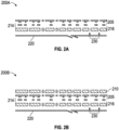
- FIGS. 2A-2B illustrate cross-sections of wound dressings that include sensor integrated substrates.
- Dressing 200A shown in FIG. 2A can include a sensor integrated substrate 205 supporting a plurality of electronic components (shown as protruding from the substrate) and a plurality of electronic connections, as described herein.
- the dressing 200A can include hard coat 214, applied to one or more electronic components or connections. In some cases, hard coat can be applied to areas where electronic components are connected to electronic connections. This can reinforce these connections. In some cases, hard coat can be applied to each of the one or more of the electronic components or connections.
- the dressing 200A can include soft coat 216, which can be applied to the entire wound facing side of the substrate.
- Soft coat 216 can be applied to an entire area of the wound facing side of the substrate to encapsulate the substrate, electronic components, and connections. In some cases, soft coat 216 can be applied to certain regions of the substrate, such as those regions supporting one or more of electronic components or connections.
- a plurality of perforations 230 can be formed through one or more of the substrate, hard coat, soft coat, and/or wound contact layer. As described herein, perforations can be made in regions or areas of the substrate that do not support electronic components or connections.
- the dressing 200A can include a protective layer 220 applied to the substrate.
- the protective layer 220 can be made of paper, such as laminated paper.
- the protective layer 220 can protect the substrate.
- the protective layer 218 can include a plurality (such as two) handles.
- the handles can be applied in a folded configuration, in which a slit separating the handles is covered by one of handles folded over the slit.
- the protective layer 218 can be similar to the protective layer used in the Allevyn Life Non-Bordered dressing.
- the substrate can be used in combination with one or more wicking layers and/or absorbent layers on the opposite, non-wound facing side (also referred to herein as second side) of the substrate.
- the wicking layer can facilitate passage of fluid through the layers below the wicking layer.
- the wicking layer can transport (or "wick") fluid away from the lower layers, such as from the substrate, toward one or more upper layers positioned over the wicking layer.
- Such one or more upper layers can include one or more absorbent materials as described herein.
- the wicking layer can be formed from foam, such as foam similar to that used in the Allevyn Life Non-Bordered dressing.
- the wicking layer can be extensible or substantially extensible.
- additional layer of soft coat 210 can be positioned over the non-wound facing side of the substrate between the substrate and the wicking layer 212.
- soft coat 210 can protect the non-wound facing side of the substrate from fluid if the substrate is formed from material that is not impermeable to fluid.
- soft coat 210 can be hydrophobic or substantially hydrophobic.
- Soft coat 210 can be made of same or different material than soft coat 218.
- Soft coat 210 can be perforated as illustrated and described. In some cases, soft coat can encapsulate the entire substrate, including both the wound facing and non-wound facing sides.
- FIGS. 3A-3B illustrate coated sensor integrated substrates 300.
- the substrates 300 are illustrated with non-wound facing side 216 up.
- the substrates 300 can be similar to any of the substrates described herein.
- PU film is typically hydrophilic and as such there are a number of elements that need to be considered in the design of a PU film mounted with electronics where there is an electrical circuit and also components that may contain chemical species (materials) that it is desirable to keep isolated from the human body (for example the chemical species that may be found within electronic components).
- the coated substrate can be perforated after coating.
- wound exudate and vapors of wound exudate will flow over all surfaces of a wound contact layer it is preferable to coat the front and back of the sheet. When this is done and then the sheet is perforated, this has the potential to expose the edge of the substrate on the cut line.
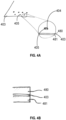
- Figures 4A-4B illustrate uncoated perforations within the substrate.
- Figure 4A and 4B illustrate an embodiment of a substrate 403 with coating.
- the substrate 403 can be flexible and can have a first, wound-facing side supporting a plurality of electronic components (not shown) and a second side opposite the first side.
- the substrate 403 comprises a plurality of perforations 405 formed though the substrate as shown in Figure 4A .
- the plurality of perforations 405 can have a wall 404 on the exterior surface of the plurality of perforations 405.
- a non-stretchable coating can be applied to at least some of the plurality of electronic components (not shown) as described with reference to Figures 2A-2B .
- a first stretchable coating 480 can be applied to the first side of the substrate.
- the first stretchable coating can be applied over the non-stretchable coating as described with reference to Figure 2A-2B .
- a second stretchable coating 481 can be applied to second side of the substrate.
- first stretchable coating and the second stretchable coating can be the same coating materials. In other cases, the first stretchable coating and the second stretchable coating can be different coating materials.
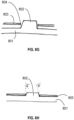
- the edge of the substrate can be exposed. As illustrated in Figures 4A-4B , the wall 404 on the exterior surface of the perforations 405 are left uncoated when the perforations are made after coating. It may be possible for liquids such as aqueous (water based) liquids or water vapor to migrate along the substrate in the plane of the substrate under the coating. It may also be possible that imperfections at the interfacial junction between the substrate and encapsulant allow liquids to travel from the wound to the electronics.
- Such imperfections may be present at the time of manufacture (for example gaps, tenting, channels between the substrate and encapsulant) or may be introduced during the life cycle of the sheet (for example delamination of the substrate from the encapsulant or the introduction of imperfections, potentially as a result of strain, or repeated strain on the sheet).
- the coated wall 404 of the perforation is illustrated in Figure 4C .
- the wall 404 of the plurality of perforations can be at least partially coated with at least one of the coatings as illustrated by coating 440.
- the exterior surface of the perforation refers to the surface of the perforation within the channel that would be exposed to wound exudate when the perforated sheet is positioned over a wound.
- the substrate can be manufactured with the method illustrated in Figure 5 .
- the electronic side of the substrate (or first side of the substrate) can be coated first 501 with one or more coatings as described herein.
- the substrate can then be perforated 502.
- the perforations can be performed in a predetermined pattern designed to avoid any of the electronic components, electronic connections, and/or electronic tracks.
- the substrate can be supported by a protective liner throughout the coating of the electronics side of the substrate and the perforations.
- the protective liner can be positioned on the side of the substrate opposite the electronic components (or the second side of the substrate). After perforation of the substrate, the protective liner can be removed 503. Once the protective liner is removed, the second side of the substrate is exposed.
- the perforated substrate is then placed on a tool with pins corresponding to each perforation 504.
- the perforated substrate is placed electronics side or first side facing down.
- the second side of the substrate is then coated 505.
- the method of manufacturing a wound dressing can include coating a first, wound-facing side or electronics side of a flexible substrate with a first coating.
- the first side of the substrate can support a plurality of electronic components.
- a first coating can be applied to at least some of the plurality of electronic components.
- the method can further include coating the first side with a second coating. In some cases, the second coating can be applied over the first coating.
- the method can then include perforating the substrate coated with the first and second coating to create a plurality of through holes or perforations through the substrate coated with the first and second coating, the plurality of perforations comprising a wall and the plurality of perforations configured to facilitate passage of fluid through the substrate.
- the substrate can have a second side opposite the first side.
- the method can further include coating the second side of the substrate with the second coating. Any protective liners can be removed from the second side of the substrate prior to coating the second side of the substrate.
- the substrate can be positioned on a tool with a plurality of pins that extend through the plurality of perforations when the second coating is applied and the second coating can coat the wall of the plurality of perforations.
- the method can further include adhering a protective layer to the substrate and the protective layer can be configured to be removed to expose the substrate before use.
- This coating technique with the perforated substrate on the tool with pins can allow for coating of the reverse side of the sheet, coating the internal channel of the perforation, and not cause a detrimental effect to the coating of the electronic face of the sheet. In some cases, this can be achieved through depositing an abundance of material at the edge of the perforation while using a tool with pins. In some cases, the tool with pins can also provide some stability to the substrate once the protective liner is removed.
- coating of the first side and coating of the second side of the substrate can be reversed.
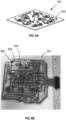
- Figure 6A illustrates an embodiment of a tool 601 with pins 602 that can be used to allow the perforations to remain open when the substrate is coated after the perforations are made.
- Figure 6B illustrates an embodiment of a perforated substrate 603 positioned on a tool 601 with pins 602 that extend through the perforations 605 of the substrate 603. As illustrated in Figure 6B , the perforations 605 can be positioned in areas of the substrate that are not supporting the electronic components and/or electronic tracks.
- Figure 6C illustrates a substrate 603 with perforations 605 being coated with a spray coating after perforations are made in the substrate.
- the substrate 603 shown in Figure 6C is positioned on a tool 601 with pins 602 that extend through the perforations to prevent closure of the perforations due to the coating application.
- the coating can extend between an exterior surface of the perforations to coat the wall on the exterior surface of the perforations similar to the illustration of the wall 404 in Figure 4C .
- the substrate 603 can be removed from the tool 601 with pins prior to the curing of the coating.
- the movement of the pins through the opening of the perforation can allow the coating to be pulled through the perforations and assist with uniformly coating the walls on the exterior surface of the perforations.
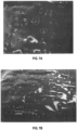
- Figure 7A shows an image of a substrate where the substrate with perforations is coated without using the tool with pins to prevent the coating material from closing the perforations. As shown with the circled regions in Figure 7A , the perforations can experience reduced size due to the coating closing the perforation.
- Figure 7B show an image of a substrate where the substrate with perforations is coated while using the tool with pins to prevent the coating from closing the perforations. As shown in Figure 7B , the perforations are mostly consistently open and more uniformity in the perforation sizes.
- the sizes and shapes of the pins can be altered to control the flow of the coating into the perforation channels.
- Various designs for the pins on the tool can be used.
- the pins on the tool can have a diameter that is smaller than the diameter of the perforations creating gaps between the perforations of the sheet and the pins. These gaps can influence the amount of uncured coating or encapsulant that can flow onto the exterior surface of the perforations to coat the wall.
- Figure 8A illustrates a substrate 803 positioned on a tool 801 with pins 802 where the diameter of the pin 802 is the same or substantially the same as the diameter of the perforation 805 in the substrate 803. As illustrated in Figure 8A , there is little to no gap between the exterior surface of the perforations of the substrate 803 and the pin 802.
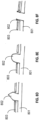
- Figure 8B illustrates a substrate 803 positioned on a tool 801 with pins 802. As illustrated in Figure 8B , there is a gap 806 between the wall 804 on the exterior surface of the perforations of the substrate 803.
- Figure 8C illustrates an embodiment with a pin having a greater height than the pin in Figure 8B .
- different shapes of pins can also be used to control the flow of the coating onto the substrate and into the channel of the perforation and/or onto the walls on the exterior surface of the perforations.
- the walls of the perforations can have a uniform coating.
- the walls of the perforations can be at least partially non-uniformly coated.
- the walls of the perforations can be coated with a pattern or a shape. The pattern or shape of the coating formed on the wall can be created by pins of different designs.
- the size of the perforations can be controlled based on the configuration of the pins.
- the perforations can be an opening that is greater than or equal to 0.25 mm in diameter (measured at its smallest dimension). In some case, the perforations can be any size or shape. In some cases, the perforations can be oval, elongated, circular, or any other shape. In some cases, the plurality of perforations can be various shapes formed in the substrate.
- the substrate can have cut outs instead of or in addition to the perforations in the substrate.
- the cut outs can be any size or shape.
- the cut outs can be oval, elongated, circular, or any other shape.
- the cut outs can be slits or rectangular cut out within the substrate.
- the plurality of cut outs can be different shapes formed in the substrate.
- the edges or walls on the exterior surface of the cut outs can be coated utilizing methods and techniques similar to those described herein with reference to the perforations.
- the cut outs can be coated using a tool with pins and the pins can have a complimentary or substantially complimentary shape but, in some cases, a smaller size to that of the cut out so as to allow the coating to pass between the exterior surface of the cut outs and the side of the pin within the cut out.
- This process can be similar to the methods and techniques described herein with reference to the perforations.
- the pins can be manufactured with design considerations to mitigate or otherwise optimally control the flow of uncured encapsulant down the pin onto the substrate and into the channel of the perforation.
- the pins can be shaped to be cylindrical, cylindrical with a concave upper surface, cylindrical with a convex upper surface, domed, conical, hollow, and/or any other shape. In some cases, designs that are not axially symmetrical can also be used.
- the surface energy of the material can be important in the design of the pins.
- materials such as silicone, uPVC, PTFE, glass and 316L stainless steel can be used.
- the surface finish of the materials can be considered.
- the surface finish of the materials can be defined, for example through stipulation of a roughness parameters such as Ra (arithmetical mean roughness value, EN ISO 42871).
- the use of a pattern can be considered.
- Other considerations can include, the temperature of the pins, the temperature of the uncured encapsulant, and/or the temperature of the complete system during application and curing.
- Shapes of the pins can control the degree of uncured coating or encapsulant that runs off from the pin.
- the shapes of the pins can be coupled with the surface energy of the material, texture, and/or temperature.
- Figures 8D-8F illustrate embodiments of different shapes of pins 802 that can be used.
- Figure 8D illustrates a substrate 803 on a tool 801 with a pin 802 with a pointed end.
- Figure 8E illustrates a substrate 803 on a tool 801 with a pin 802 with a dome shape. In some cases, the pointed end or dome shape can help the coating flow down the pin into the exterior surface of the perforations.
- Figure 8F illustrates a substrate 803 on a tool 801 with a pin 802 with a channel in the pin.
- Figures 8G and 8H illustrate a tool 801 with pins 802 that are tapered.
- the pins can be tapered to control the liquid flow onto the exterior surface of the perforation channel and thereby coating the wall of the perforations.
- the pins can be tapered to aid in withdrawal of the pins following curing of the coating or encapsulant.
- the pins can be tapered with a defined angle as illustrated in Figure 8H .
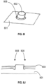
- gutters can be introduced into the tool to accommodate for surplus uncured encapsulant.
- the gutters 808 can be positioned at the base of the pin 802 where the pin 802 connects to the remainder of the tool 801as illustrated in Figures 8I and 8J .
- the gap permitted between registration perforations 910 and corresponding registration pins 911 may be very small for improved accuracy.
- the gap permitted between pins 902 and substrate perforations 905 can be optimized with consideration of liquid flow around the pin 902 and onto the exterior surface of the perforation channel as described herein and illustrated in Figure 9B .
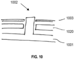
- a tool base plate 1020 can be used to support the substrate 1003.
- the tool base plate 1020 as shown in Figure 10 can be made to facilitate extraction of the pins 1002 whilst supporting the electronics substrate 1003 and/or providing a channel for surplus coating or encapsulant to flow down.
- the tool base plate 1020 can be positioned between the substrate 1003 and the tool 1001 with pins 1002.
- the substrate 1003 can be supported by the tool base plate 1020 when the substrate 1003 is withdrawn from the tool 1001 with pins 1002.
- Pins may be made with a profile such that grooves are introduced into the exterior surface of the perforation channel when the wall is coated.
- Figure 11 illustrates an embodiment of a conical pin with ridges or a truncated cone with grooves. The conical pin with ridges can be used to create grooves on the exterior surface of the perforations. With other cutouts or shapes on the pins, many other designs are also feasible to create patterns or shapes on the exterior surface of the perforations when the wall is coated.
- the encapsulant is UV curable
- Some material used for the substrate can inhibit transfer of given frequencies of UV and as such may inhibit curing.
- tools made of UV transmissive materials or with UV transmissive pins may be considered. Such materials can include: Fused Silica, Quartz, Vycor, formulations of Pyrex, Sapphire and a variety of fluoride compounds.
- the substrate may be subject to UV curing on both sides following removal of the tool with pins.
- a protective liner can be applied to the second side of the substrate as shown in Figures 2A-2B .
- the substrate can then be perforated to create the perforations as described herein.
- the cutting and perforation can also be extended to cut the outline of the substrate too.
- the substrate can be turned over and any protective liners can be removed.
- the substrate can be applied to the tool with pins and the design of the tool can include a tray such that the outer edge of the sheet is about 2mm from the edge of the tray or any suitable distance from the end of the tray to allow the tray to extend beyond the outer perimeter of the substrate.
- the soft coat When the soft coat is spread and/or sprayed onto the tool with pins and over the substrate it can cover the reverse side of the substrate and encapsulates all the cut edges of the substrate. In some cases, the soft coat can be gently spread and allowed to settle which can assist in the coating process. In some cases, alignment of the substrate on the tool with pins can be critical to ensure that the substrate sits in the nominal centre (i.e. nominally concentrically) of each perforation. Failure to do so can result in a reduced amount of coating encapsulating the substrate. In the cases of circular perforations, this would result with a (smaller) perforation in the soft coat that was excentric relative to the (larger) perforation in the substrate that it sits in. In other cases, the (smaller) perforation in the soft coat can be concentric relative to the (larger) perforation in the substrate that it sits in.
- the soft coat could be applied to the second side of the substrate without the use of a tool with pins.
- a second perforation step can be performed to finalize the perforation process.
- This second perforation step could utilize an optical visioning system which can aid significantly with alignment. After the second perforation step, plugs of silicone may need to be removed from the perforation spots.
- the steps for processing the substrate can be similar to those described here with some changes. Similar to the steps described previously, the sensor sheet can be hard coated on the component side and then the soft coat can be applied on the component side or first side of the substrate.
- the existing process step of perforating the substrate is carried out. In some cases, the process of cutting the perforation can also be extended to cut the outline of the substrate too.
- the substrate can be turned over and any protective liners can be removed.
- the substrate can be placed on a flat tray. In some cases, the tray can allow for the outer edge of the substrate to be about 1cm from the edge of the tray.
- any size tray can be used that provides a suitable distance from the outer perimeter of the substrate to the end of the tray to allow the tray to extend beyond the outer perimeter of the substrate.
- the soft coat When the soft coat is spread or sprayed onto the tray and over the substrate it can cover the second side of the substrate and fill the perforations and encapsulate the cut edges of the substrate.
- the soft coat can be gently spread and allowed to settle which can assist in coating the entire substrate and edges. With this process, the alignment may not be critical.
- the resulting substrate will then undergo a second laser perforation step, whereby the second set of perforations through the soft coat can be stepped back by a defined amount from the first perforations in the substrate providing smaller bores and a larger outer sheet outline then done with the first cutting step. With these steps the substrate can be encapsulated with coating.
- one or more electronic components can be positioned on the side of a substrate opposite the side that faces the wound.
- Systems and methods described herein are equally applicable to such wound contact layers. Although certain embodiments described herein relate to wound dressings, systems and methods disclosed herein are not limited to wound dressings or medical applications. Systems and methods disclosed herein are generally applicable to electronic devices in general, such as electronic devices that can be worn by or applied to a user.
- any value of a threshold, limit, duration, etc. provided herein is not intended to be absolute and, thereby, can be approximate.
- any threshold, limit, duration, etc. provided herein can be fixed or varied either automatically or by a user.
- relative terminology such as exceeds, greater than, less than, etc. in relation to a reference value is intended to also encompass being equal to the reference value. For example, exceeding a reference value that is positive can encompass being equal to or greater than the reference value.
- relative terminology such as exceeds, greater than, less than, etc. in relation to a reference value is intended to also encompass an inverse of the disclosed relationship, such as below, less than, greater than, etc. in relations to the reference value.
- blocks of the various processes may be described in terms of determining whether a value meets or does not meet a particular threshold, the blocks can be similarly understood, for example, in terms of a value (i) being below or above a threshold or (ii) satisfying or not satisfying a threshold.
- the various components illustrated in the figures may be implemented as software or firmware on a processor, controller, ASIC, FPGA, or dedicated hardware.
- Hardware components such as controllers, processors, ASICs, FPGAs, and the like, can include logic circuitry.
- the features and attributes of the specific embodiments disclosed above may be combined in different ways to form additional embodiments, all of which fall within the scope of the present disclosure.
- the term "or” is used in its inclusive sense (and not in its exclusive sense) so that when used, for example, to connect a list of elements, the term “or” means one, some, or all of the elements in the list.
- the term “each,” as used herein, in addition to having its ordinary meaning, can mean any subset of a set of elements to which the term “each” is applied.
Landscapes
- Health & Medical Sciences (AREA)
- Life Sciences & Earth Sciences (AREA)
- Engineering & Computer Science (AREA)
- Public Health (AREA)
- Veterinary Medicine (AREA)
- Biomedical Technology (AREA)
- Heart & Thoracic Surgery (AREA)
- Animal Behavior & Ethology (AREA)
- General Health & Medical Sciences (AREA)
- Vascular Medicine (AREA)
- Physics & Mathematics (AREA)
- Biophysics (AREA)
- Pathology (AREA)
- Medical Informatics (AREA)
- Molecular Biology (AREA)
- Surgery (AREA)
- Manufacturing & Machinery (AREA)
- Dermatology (AREA)
- Nuclear Medicine, Radiotherapy & Molecular Imaging (AREA)
- Radiology & Medical Imaging (AREA)
- Materials For Medical Uses (AREA)
- Media Introduction/Drainage Providing Device (AREA)
Applications Claiming Priority (2)
| Application Number | Priority Date | Filing Date | Title |
|---|---|---|---|
| GBGB1918856.4A GB201918856D0 (en) | 2019-12-19 | 2019-12-19 | Sensor integrated dressings and systems |
| PCT/EP2020/086812 WO2021123014A1 (en) | 2019-12-19 | 2020-12-17 | Sensor integrated dressings and systems |
Publications (2)
| Publication Number | Publication Date |
|---|---|
| EP4076312A1 EP4076312A1 (en) | 2022-10-26 |
| EP4076312B1 true EP4076312B1 (en) | 2025-04-23 |
Family
ID=69322999
Family Applications (1)
| Application Number | Title | Priority Date | Filing Date |
|---|---|---|---|
| EP20841897.0A Active EP4076312B1 (en) | 2019-12-19 | 2020-12-17 | Sensor integrated dressings and systems |
Country Status (5)
| Country | Link |
|---|---|
| US (2) | US12527522B2 (https=) |
| EP (1) | EP4076312B1 (https=) |
| JP (1) | JP7669370B2 (https=) |
| GB (1) | GB201918856D0 (https=) |
| WO (1) | WO2021123014A1 (https=) |
Family Cites Families (471)
| Publication number | Priority date | Publication date | Assignee | Title |
|---|---|---|---|---|
| US3896802A (en) | 1974-04-19 | 1975-07-29 | American Cyanamid Co | Flexible flocked dressing |
| US4334530A (en) | 1980-09-12 | 1982-06-15 | Hassell Donald S | Indicia-bearing adhesive bandages |
| US5090410A (en) | 1989-06-28 | 1992-02-25 | Datascope Investment Corp. | Fastener for attaching sensor to the body |
| US5642096A (en) | 1992-03-20 | 1997-06-24 | Paromed Medizintechnik Gmbh | Device for prevention of ulcers in the feet of diabetes patients |
| SE500972C2 (sv) | 1992-03-30 | 1994-10-10 | Moelnlycke Ab | Förfarande och anordning för tillverkning av sårförband samt ett sårförband tillverkat medelst förfarandet |
| US5253654A (en) | 1992-04-30 | 1993-10-19 | Thomas Berten R | Orthopedic weight monitor |
| DE69427716T2 (de) | 1993-03-10 | 2002-06-13 | Nichiban Co. Ltd., Tokio/Tokyo | Klebeverband zur Blutstillung |
| US6178342B1 (en) | 1993-09-09 | 2001-01-23 | Vasamedics | Surface perfusion pressure monitoring system |
| US5678448A (en) | 1994-01-14 | 1997-10-21 | Fullen Systems, Inc. | System for continuously measuring forces applied by the foot |
| GB9523640D0 (en) | 1995-11-18 | 1996-01-17 | Bristol Myers Squibb Co | Bandaging system |
| US5703225A (en) | 1995-12-13 | 1997-12-30 | Kimberly-Clark Worldwide, Inc. | Sulfonated cellulose having improved absorbent properties |
| GB9615895D0 (en) | 1996-07-29 | 1996-09-11 | Thames Medical Ltd | Pulse oximeter |
| DE19632273A1 (de) * | 1996-08-09 | 1998-02-12 | Helge Zwosta | Körpersensorik |
| WO1998032790A1 (en) * | 1997-01-27 | 1998-07-30 | Flowgenix Corporation | Porous articles with surface functionality and uses thereof |
| US20020099318A1 (en) | 1997-05-16 | 2002-07-25 | Susan Suehr | Multi-layer compression bandage |
| DE19722075C1 (de) | 1997-05-27 | 1998-10-01 | Wilhelm Dr Med Fleischmann | Vorrichtung zur Applikation von Wirkstoffen an einer Wundoberfläche |
| US7206623B2 (en) | 2000-05-02 | 2007-04-17 | Sensys Medical, Inc. | Optical sampling interface system for in vivo measurement of tissue |
| US5836990A (en) | 1997-09-19 | 1998-11-17 | Medtronic, Inc. | Method and apparatus for determining electrode/tissue contact |
| US6381482B1 (en) | 1998-05-13 | 2002-04-30 | Georgia Tech Research Corp. | Fabric or garment with integrated flexible information infrastructure |
| US6095992A (en) | 1998-04-06 | 2000-08-01 | Augustine Medical, Inc. | Wound treatment apparatus for normothermic treatment of wounds |
| US6343224B1 (en) | 1998-10-15 | 2002-01-29 | Sensidyne, Inc. | Reusable pulse oximeter probe and disposable bandage apparatus |
| FR2785544B1 (fr) | 1998-11-09 | 2001-01-05 | Lhd Lab Hygiene Dietetique | Electrode de transfert d'un courant electrique traversant la peau d'un patient |
| WO2000043046A2 (en) | 1999-01-21 | 2000-07-27 | Rhoda Zione | Wound management system and wound dressing |
| US7047054B2 (en) | 1999-03-12 | 2006-05-16 | Cas Medical Systems, Inc. | Laser diode optical transducer assembly for non-invasive spectrophotometric blood oxygenation monitoring |
| US6856821B2 (en) | 2000-05-26 | 2005-02-15 | Kci Licensing, Inc. | System for combined transcutaneous blood gas monitoring and vacuum assisted wound closure |
| US6669663B1 (en) | 1999-04-30 | 2003-12-30 | Medtronic, Inc. | Closed loop medicament pump |
| US20030208148A1 (en) | 1999-11-01 | 2003-11-06 | Sullivan John Patrick | Adhesive bandage with soft, three-dimensional toy figure |
| US6566575B1 (en) * | 2000-02-15 | 2003-05-20 | 3M Innovative Properties Company | Patterned absorbent article for wound dressing |
| US6517484B1 (en) | 2000-02-28 | 2003-02-11 | Wilk Patent Development Corporation | Ultrasonic imaging system and associated method |
| US6639674B2 (en) | 2000-03-28 | 2003-10-28 | Board Of Regents, The University Of Texas System | Methods and apparatus for polarized reflectance spectroscopy |
| CA2405848C (en) | 2000-04-17 | 2010-11-09 | Vivometrics, Inc. | Systems and methods for ambulatory monitoring of physiological signs |
| US7520875B2 (en) | 2001-04-06 | 2009-04-21 | Mattioli Engineering Ltd. | Method and apparatus for skin absorption enhancement and transdermal drug delivery |
| US6889165B2 (en) | 2001-07-02 | 2005-05-03 | Battelle Memorial Institute | Application specific intelligent microsensors |
| EP1480555B1 (en) | 2002-01-23 | 2007-08-22 | Bang & Olufsen Medicom A/S | A blood pressure measuring device with a cuff of two openable concave shell parts |
| US6980852B2 (en) | 2002-01-25 | 2005-12-27 | Subqiview Inc. | Film barrier dressing for intravascular tissue monitoring system |
| GB0202654D0 (en) | 2002-02-06 | 2002-03-20 | Univ Nottingham | Examination of superficial regions of a body |
| US7158660B2 (en) | 2002-05-08 | 2007-01-02 | Gee Jr James W | Method and apparatus for detecting structures of interest |
| US20070100666A1 (en) | 2002-08-22 | 2007-05-03 | Stivoric John M | Devices and systems for contextual and physiological-based detection, monitoring, reporting, entertainment, and control of other devices |
| US7846141B2 (en) | 2002-09-03 | 2010-12-07 | Bluesky Medical Group Incorporated | Reduced pressure treatment system |
| US8111165B2 (en) | 2002-10-02 | 2012-02-07 | Orthocare Innovations Llc | Active on-patient sensor, method and system |
| JP2004158605A (ja) | 2002-11-06 | 2004-06-03 | Konica Minolta Holdings Inc | プリント配線基板、及びプリント配線基板の導電性筐体への取付方法 |
| GB0228375D0 (en) | 2002-12-05 | 2003-01-08 | Innovation And Entpr Off Of | Wound mapping |
| US6847004B2 (en) * | 2003-01-10 | 2005-01-25 | General Electric Company | Process of removing a ceramic coating deposit in a surface hole of a component |
| US7267671B2 (en) | 2003-02-07 | 2007-09-11 | Alfred E. Mann Institute For Biomedical Research At The University Of Southern California | Surgical drain with sensors for monitoring fluid lumen |
| GB0303797D0 (en) | 2003-02-19 | 2003-03-26 | Huntleigh Technology Plc | Blood assessment |
| US7706862B2 (en) | 2003-04-17 | 2010-04-27 | Research Foundation Of The City University Of New York | Detecting human cancer through spectral optical imaging using key water absorption wavelengths |
| US20060181791A1 (en) | 2003-07-31 | 2006-08-17 | Van Beek Michael C | Method and apparatus for determining a property of a fluid which flows through a biological tubular structure with variable numerical aperture |
| WO2005023361A2 (en) | 2003-09-10 | 2005-03-17 | Power Paper Ltd. | Disposable electric bandage |
| CA2539184A1 (en) | 2003-09-19 | 2005-03-31 | The General Hospital Corporation | Fluorescence polarization imaging devices and methods |
| TWI220787B (en) | 2003-10-24 | 2004-09-01 | Asustek Comp Inc | Electric device with electrostatic discharge protection structure thereof |
| WO2005044090A2 (en) | 2003-11-04 | 2005-05-19 | General Hospital Corporation | Respiration motion detection and health state assessment system |
| CN1894796B (zh) | 2003-12-15 | 2010-09-01 | 株式会社半导体能源研究所 | 薄膜集成电路器件的制造方法和非接触薄膜集成电路器件及其制造方法 |
| ES2348306T3 (es) | 2004-02-13 | 2010-12-02 | Convatec Technologies Inc. | Apósito de multiples capas para heridas. |
| CN100444784C (zh) | 2004-02-27 | 2008-12-24 | 皇家飞利浦电子股份有限公司 | 用于监测、分析和通信生理状态的可佩带的无线装置 |
| WO2005084537A1 (en) | 2004-03-08 | 2005-09-15 | Medicus Engineering Aps | A method and an instrument for measuring of physiological parameters |
| WO2005092177A1 (en) | 2004-03-22 | 2005-10-06 | Bodymedia, Inc. | Non-invasive temperature monitoring device |
| US7884258B2 (en) | 2004-04-13 | 2011-02-08 | Boehringer Technologies, L.P. | Wound contact device |
| GB0408492D0 (en) | 2004-04-16 | 2004-05-19 | Univ Strathclyde | Performance measurement of wound dressings |
| US7753894B2 (en) | 2004-04-27 | 2010-07-13 | Smith & Nephew Plc | Wound cleansing apparatus with stress |
| GB0508528D0 (en) | 2005-04-27 | 2005-06-01 | Smith & Nephew | SAI with macrostress |
| US7201063B2 (en) | 2004-04-30 | 2007-04-10 | Taylor Geoffrey L | Normal force gradient/shear force sensors and method of measuring internal biological tissue stress |
| US7521292B2 (en) | 2004-06-04 | 2009-04-21 | The Board Of Trustees Of The University Of Illinois | Stretchable form of single crystal silicon for high performance electronics on rubber substrates |
| WO2006009767A1 (en) | 2004-06-18 | 2006-01-26 | Neuronetrix, Inc | Wireless electrode for biopotential measurement |
| SE0401632D0 (sv) | 2004-06-24 | 2004-06-24 | Innovation Team Ab | Medel och sätt att detektera blodläckage från sår |
| WO2006029035A1 (en) | 2004-09-02 | 2006-03-16 | Philometron, Inc. | Monitoring platform for wound and ulcer monitoring and detection |
| US20060058690A1 (en) | 2004-09-10 | 2006-03-16 | Optical Sensors, Inc. | Method and instrument for automated measurement of skin perfusion pressure |
| ATE418294T1 (de) | 2004-10-05 | 2009-01-15 | Koninkl Philips Electronics Nv | Hautbehandlungsvorrichtung mit strahlungsemissionsschutz |
| US8498681B2 (en) | 2004-10-05 | 2013-07-30 | Tomophase Corporation | Cross-sectional mapping of spectral absorbance features |
| NL1027236C2 (nl) | 2004-10-13 | 2006-04-18 | Innova Medical V O F | Verbandmiddel voor een gekwetst lichaamsdeel. |
| US20060142560A1 (en) | 2004-12-29 | 2006-06-29 | Glasser Wolfgang G | Sulfoalkylated cellulose |
| US9597024B2 (en) | 2005-02-09 | 2017-03-21 | Medici Instruments Llc | Methods and apparatuses for noninvasive determinations of analytes |
| AU2006218256B2 (en) | 2005-02-28 | 2010-07-08 | Commonwealth Scientific And Industrial Research Organisation | Flexible electronic device |
| US20060241495A1 (en) | 2005-03-23 | 2006-10-26 | Eastman Kodak Company | Wound healing monitoring and treatment |
| EP1709947A1 (en) | 2005-04-08 | 2006-10-11 | 3M Innovative Properties Company | Compression bandage system |
| AU2006235722A1 (en) | 2005-04-14 | 2006-10-19 | Hidalgo Limited | Apparatus and system for monitoring |
| US8060174B2 (en) | 2005-04-15 | 2011-11-15 | Dexcom, Inc. | Analyte sensing biointerface |
| WO2007030379A2 (en) | 2005-09-06 | 2007-03-15 | Optical Sensors Incorporated | System for automated measurement of skin perfusion pressure |
| EP1922095A2 (en) | 2005-09-07 | 2008-05-21 | Tyco Healthcare Group LP | Wound dressing with vacuum reservoir |
| BRPI0616591A2 (pt) | 2005-09-07 | 2011-06-28 | Tyco Healthcare | aparelho de curativo de ferimento independente |
| EP1922045B1 (en) | 2005-09-07 | 2012-11-07 | Tyco Healthcare Group LP | Self contained wound dressing with micropump |
| GB0519836D0 (en) | 2005-09-29 | 2005-11-09 | Smartlife Technology Ltd | Contact sensors |
| US8032210B2 (en) | 2005-10-06 | 2011-10-04 | Spinematrix, Inc. | EMG diagnostic system and method |
| US7420472B2 (en) | 2005-10-16 | 2008-09-02 | Bao Tran | Patient monitoring apparatus |
| US7877866B1 (en) | 2005-10-26 | 2011-02-01 | Second Sight Medical Products, Inc. | Flexible circuit electrode array and method of manufacturing the same |
| US8333874B2 (en) | 2005-12-09 | 2012-12-18 | Flexible Medical Systems, Llc | Flexible apparatus and method for monitoring and delivery |
| CN101341424B (zh) | 2005-12-22 | 2012-07-18 | 皇家飞利浦电子股份有限公司 | 磁感应断层成像系统和方法 |
| US7816577B2 (en) | 2006-02-13 | 2010-10-19 | Aalnex, Inc. | Wound shield |
| CA2538940A1 (en) | 2006-03-03 | 2006-06-22 | James W. Haslett | Bandage with sensors |
| DE102006045138A1 (de) | 2006-03-27 | 2007-11-15 | Siemens Ag | Vorrichtung, Sensor, Sensorelement sowie Verfahren zur Vermessung des Wirbelsäulenverlaufs und von Verlaufsänderungen der Wirbelsäule |
| US7607243B2 (en) | 2006-05-03 | 2009-10-27 | Nike, Inc. | Athletic or other performance sensing systems |
| US8644911B1 (en) | 2006-06-30 | 2014-02-04 | Hypermed Imaging, Inc. | OxyVu-1 hyperspectral tissue oxygenation (HTO) measurement system |
| GB2439750A (en) | 2006-07-06 | 2008-01-09 | Wound Solutions Ltd | Monitoring a limb wound |
| WO2008006150A1 (en) | 2006-07-11 | 2008-01-17 | Citech Research Ip Pty Ltd | Bio-activity data capture and transmission |
| WO2008010604A1 (en) | 2006-07-19 | 2008-01-24 | School Juridical Person Kitasato Gakuen | Blood vessel imaging device and system for analyzing blood vessel distribution |
| US9254220B1 (en) | 2006-08-29 | 2016-02-09 | Vasamed, Inc. | Method and system for assessing severity and stage of peripheral arterial disease and lower extremity wounds using angiosome mapping |
| US7890153B2 (en) | 2006-09-28 | 2011-02-15 | Nellcor Puritan Bennett Llc | System and method for mitigating interference in pulse oximetry |
| GB0620061D0 (en) | 2006-10-10 | 2006-11-22 | Medical Device Innovations Ltd | Oesophageal treatment apparatus and method |
| US7785301B2 (en) | 2006-11-28 | 2010-08-31 | Vadim V Yuzhakov | Tissue conforming microneedle array and patch for transdermal drug delivery or biological fluid collection |
| US8019401B1 (en) | 2006-12-04 | 2011-09-13 | Smithmarks, Inc. | Stretchable electrode and method of making physiologic measurements |
| NZ551819A (en) | 2006-12-04 | 2009-03-31 | Zephyr Technology Ltd | Impact detection system |
| US8238996B2 (en) | 2006-12-05 | 2012-08-07 | Tyco Healthcare Group Lp | Electrode array |
| US8100834B2 (en) | 2007-02-27 | 2012-01-24 | J&M Shuler, Inc. | Method and system for monitoring oxygenation levels of a compartment for detecting conditions of a compartment syndrome |
| US7687678B2 (en) | 2007-05-10 | 2010-03-30 | Cisco Technology, Inc. | Electronic bandage with flexible electronic controller |
| EP2005886B1 (en) | 2007-06-19 | 2011-09-14 | Biocompatibles UK Limited | Method and apparatus for measuring skin texture |
| WO2009023937A1 (en) | 2007-08-22 | 2009-02-26 | Commonwealth Scientific And Industrial Research Organisation | A system, garment and method |
| EP2194847A1 (en) | 2007-09-14 | 2010-06-16 | Corventis, Inc. | Adherent device with multiple physiological sensors |
| WO2009052607A1 (en) | 2007-10-24 | 2009-04-30 | Perceptronix Medical Inc. | Method and apparatus for microvascular oxygenation imaging |
| US8116838B2 (en) | 2007-11-27 | 2012-02-14 | Carnegie Mellon University | Medical device for diagnosing pressure ulcers |
| GB0723898D0 (en) | 2007-12-06 | 2008-01-16 | Wound Solutions Ltd | Wound treatment device and method |
| CA2708497A1 (en) | 2007-12-10 | 2009-06-18 | Isis Biopolymer Llc | Iontophoretic drug delivery device and software application |
| CA2711620A1 (en) | 2008-01-08 | 2009-07-16 | Bluesky Medical Group Inc. | Sustained variable negative pressure wound treatment and method of controlling same |
| ATE514375T1 (de) | 2008-01-08 | 2011-07-15 | Cardiac Pacemakers Inc | Impedanzmessung und demodulation anhand einer implantierbaren vorrichtung |
| US20090177051A1 (en) | 2008-01-09 | 2009-07-09 | Heal-Ex, Llc | Systems and methods for providing sub-dressing wound analysis and therapy |
| GB0801264D0 (en) | 2008-01-24 | 2008-02-27 | Univ Ulster | Electrically enhances wound healing system and method |
| WO2009103034A2 (en) | 2008-02-13 | 2009-08-20 | Board Of Regents, The University Of Texas System | System, method and apparatus for an amorphous iridium oxide film ph sensor |
| US20090209896A1 (en) | 2008-02-19 | 2009-08-20 | Selevan James R | Method and apparatus for time-dependent and temperature-dependent clinical alert |
| EP2257320A2 (en) | 2008-03-12 | 2010-12-08 | Bluesky Medical Group Inc. | Negative pressure dressing and method of using same |
| US8161826B1 (en) | 2009-03-05 | 2012-04-24 | Stryker Corporation | Elastically stretchable fabric force sensor arrays and methods of making |
| JP2009225863A (ja) | 2008-03-19 | 2009-10-08 | Nemoto Kyorindo:Kk | 剥離シート付き両面粘着シート |
| WO2009120951A2 (en) | 2008-03-28 | 2009-10-01 | Nordson Corporation | Automated conformal coating inspection system and methods of use |
| US7792334B2 (en) | 2008-03-31 | 2010-09-07 | Immersion Corporation | Locating blood vessels |
| CN102036600B (zh) | 2008-05-23 | 2014-08-06 | 皇家飞利浦电子股份有限公司 | 适于携带传感器、致动器或者电子元件的基底层 |
| WO2009141777A1 (en) | 2008-05-23 | 2009-11-26 | Koninklijke Philips Electronics N.V. | A substrate layer adapted to carry sensors, actuators or electrical components |
| US8480641B2 (en) | 2008-06-13 | 2013-07-09 | Premco Medical Systems, Inc. | Negative pressure wound treatment apparatus and method |
| CN102098959B (zh) | 2008-07-18 | 2014-09-24 | 弗莱康股份有限公司 | 用于心电图检测系统的高阻抗信号检测系统和方法 |
| US20100022990A1 (en) | 2008-07-25 | 2010-01-28 | Boehringer Technologies, L.P. | Pump system for negative pressure wound therapy and improvements thereon |
| WO2010020919A1 (en) | 2008-08-22 | 2010-02-25 | Koninklijke Philips Electronics N.V. | Monitoring of a fluid accumulation in a body of a person |
| US8389862B2 (en) | 2008-10-07 | 2013-03-05 | Mc10, Inc. | Extremely stretchable electronics |
| US9221963B2 (en) | 2008-11-27 | 2015-12-29 | Speciality Fibres And Materials Ltd. | Absorbent material |
| US8503712B2 (en) | 2008-12-31 | 2013-08-06 | Motorola Mobility Llc | Method and apparatus for determining blood oxygenation using a mobile communication device |
| FR2940904B1 (fr) | 2009-01-13 | 2012-08-31 | Urgo Laboratoires | Systeme de mesure de pression d'interface |
| DE102009008885A1 (de) | 2009-02-14 | 2010-08-26 | Fresenius Medical Care Deutschland Gmbh | Vorrichtung zum Detektieren von Feuchtigkeit für eine Vorrichtung zur Überwachung eines Zugangs zu einem Patienten, insbesondere zur Überwachung des Gefäßzugangs bei einer extrakkorporalen Blutbehandlung |
| WO2010105053A2 (en) | 2009-03-13 | 2010-09-16 | Corventis, Inc. | Acute patient management for military and emergency applications |
| US11278237B2 (en) | 2010-04-22 | 2022-03-22 | Leaf Healthcare, Inc. | Devices, systems, and methods for preventing, detecting, and treating pressure-induced ischemia, pressure ulcers, and other conditions |
| US8823934B2 (en) | 2009-03-27 | 2014-09-02 | Brightex Bio-Photonics Llc | Methods and systems for imaging and modeling skin using polarized lighting |
| US8332053B1 (en) | 2009-04-28 | 2012-12-11 | Hrl Laboratories, Llc | Method for fabrication of a stretchable electronic skin |
| US20110004088A1 (en) | 2009-05-13 | 2011-01-06 | Kurt Paul Grossman | The ecg shirt |
| GB0912009D0 (en) | 2009-07-10 | 2009-08-19 | Univ Strathclyde | Sensor |
| US8535282B2 (en) | 2009-07-14 | 2013-09-17 | Southwest Research Institute | Wound healing sensor techniques |
| US8447375B2 (en) | 2009-08-13 | 2013-05-21 | J&M Shuler Medical, Inc. | Methods and dressing systems for promoting healing of injured tissue |
| WO2011022418A2 (en) | 2009-08-17 | 2011-02-24 | The Regents Of The University Of California | Distributed external and internal wireless sensor systems for characterization of surface and subsurface biomedical structure and condition |
| US20110218756A1 (en) | 2009-10-01 | 2011-09-08 | Mc10, Inc. | Methods and apparatus for conformal sensing of force and/or acceleration at a person's head |
| GB0919659D0 (en) | 2009-11-10 | 2009-12-23 | Convatec Technologies Inc | A component for a wound dressing |
| GB0921477D0 (en) | 2009-12-08 | 2010-01-20 | Moor Instr Ltd | Apparatus for measuring blood parameters |
| US10441185B2 (en) | 2009-12-16 | 2019-10-15 | The Board Of Trustees Of The University Of Illinois | Flexible and stretchable electronic systems for epidermal electronics |
| US8943897B2 (en) | 2009-12-30 | 2015-02-03 | Societe de Commercialisation des Produits de la Recherche Appliquee—Socpra-Sciences et Genie S.E.C. | Carbon nanotubes based sensing elements and system for monitoring and mapping force, strain and stress |
| WO2011082420A1 (en) | 2010-01-04 | 2011-07-07 | John Stephan | Illuminatable apparatus and method of manufacturing same |
| FR2955763B1 (fr) | 2010-02-02 | 2012-03-09 | Commissariat Energie Atomique | Sonde optique peroperatoire bi-spectrale |
| WO2011106792A2 (en) | 2010-02-26 | 2011-09-01 | Myskin, Inc. | Analytic methods of tissue evaluation |
| JP5663900B2 (ja) | 2010-03-05 | 2015-02-04 | セイコーエプソン株式会社 | 分光センサー装置及び電子機器 |
| EP2595707B1 (en) | 2010-03-07 | 2023-04-19 | Leaf Healthcare, Inc. | Systems for preventing, detecting, and treating pressure-induced ischemia, pressure ulcers, and other conditions |
| US9427506B2 (en) | 2010-03-31 | 2016-08-30 | Kci Licensing, Inc. | System and method for locating fluid leaks at a drape using sensing techniques |
| US8553223B2 (en) | 2010-03-31 | 2013-10-08 | Covidien Lp | Biodegradable fibers for sensing |
| US9061095B2 (en) | 2010-04-27 | 2015-06-23 | Smith & Nephew Plc | Wound dressing and method of use |
| US20130317367A1 (en) | 2010-05-04 | 2013-11-28 | Michael Simms Shuler | Method and system for providing versatile nirs sensors |
| PT4122383T (pt) | 2010-05-08 | 2025-05-02 | Univ California | Aparelho de deteção de scanner sem para a deteção precoce de úlceras |
| EP2568874A4 (en) | 2010-05-08 | 2014-10-29 | Univ California | METHOD, SYSTEM AND DEVICE FOR PRINTING IMAGE |
| US8182425B2 (en) | 2010-05-18 | 2012-05-22 | Johnson & Johnson Consumer Companies, Inc. | Method for measuring skin hydration |
| US8525340B2 (en) | 2010-06-11 | 2013-09-03 | Premitec, Inc. | Flexible electronic devices and related methods |
| WO2012001465A1 (en) | 2010-06-29 | 2012-01-05 | Indian Institute Of Technology Kanpur | Flexible temperature sensor and sensor array |
| US9314175B2 (en) | 2010-07-08 | 2016-04-19 | TCI3—Pressure Applications, LLC | Compartment syndrome monitoring systems and methods |
| US20120029307A1 (en) | 2010-07-27 | 2012-02-02 | Carefusion 303, Inc. | Vital-signs monitor with spaced electrodes |
| US20120029306A1 (en) | 2010-07-27 | 2012-02-02 | Carefusion 303, Inc. | Vital-signs monitor with encapsulation arrangement |
| US9585620B2 (en) | 2010-07-27 | 2017-03-07 | Carefusion 303, Inc. | Vital-signs patch having a flexible attachment to electrodes |
| US20120316486A1 (en) | 2010-08-20 | 2012-12-13 | Andrew Cheung | Surgical Component Navigation Systems And Methods |
| US9000251B2 (en) | 2010-08-26 | 2015-04-07 | Combat Medical Systems, Llc | Draining wound dressing |
| US20120109034A1 (en) | 2010-10-27 | 2012-05-03 | Kci Licensing, Inc. | Interactive, wireless reduced-pressure dressings, methods, and systems |
| DE102010051459A1 (de) | 2010-11-17 | 2012-05-24 | Harald Pötzschke | Wundüberwachung mit textilen Messgrößenwandler-Systemen |
| ES2541629T3 (es) | 2010-11-17 | 2015-07-22 | Smart Solutions Technologies, S.L. | Sensor para adquirir señales fisiológicas |
| WO2012074509A1 (en) | 2010-11-30 | 2012-06-07 | Avery Dennison Corporation | Sensing patch applications |
| CN103347561B (zh) | 2010-12-08 | 2016-09-07 | 康沃特克科技公司 | 用于评估伤口分泌液的集成系统 |
| US20120165717A1 (en) | 2010-12-22 | 2012-06-28 | Convatec Technologies Inc. | Medical compression product, system utilizing such product, and program for use therewith |
| WO2012100090A2 (en) | 2011-01-19 | 2012-07-26 | The Regents Of The University Of California | Apparatus, systems, and methods for tissue oximetry and perfusion imaging |
| GB2487758A (en) | 2011-02-03 | 2012-08-08 | Isansys Lifecare Ltd | Health monitoring electrode assembly |
| EP2672893B1 (en) | 2011-02-13 | 2021-03-31 | Edwards Lifesciences Corporation | Nirs sensor assembly including electrically conductive and optically transparent emi shielding |
| JP2014514032A (ja) | 2011-03-11 | 2014-06-19 | プロテウス デジタル ヘルス, インコーポレイテッド | 様々な物理的構成を備えた着用式個人身体関連装置 |
| US8818478B2 (en) | 2011-03-31 | 2014-08-26 | Adidas Ag | Sensor garment |
| JP2014514089A (ja) | 2011-04-12 | 2014-06-19 | ケーシーアイ ライセンシング インコーポレイテッド | 蒸発装置を備える減圧ドレッシング、システム、および方法 |
| US8838228B2 (en) | 2011-04-15 | 2014-09-16 | Arthur Beisang, III | Systems and methods for reducing the proliferation of microorganisms |
| US20120271265A1 (en) | 2011-04-20 | 2012-10-25 | Frederick Michael Langdon | Zero-Strain Stretch Laminate with Enhanced Strength, Appearance and Tactile Features, and Absorbent Articles Having Components Formed Therefrom |
| KR20120119523A (ko) | 2011-04-21 | 2012-10-31 | 방부복 | 혈관 위치 탐지용 장치 |
| US10117705B2 (en) | 2011-05-16 | 2018-11-06 | Covidien Lp | Optical recognition of tissue and vessels |
| US8934965B2 (en) | 2011-06-03 | 2015-01-13 | The Board Of Trustees Of The University Of Illinois | Conformable actively multiplexed high-density surface electrode array for brain interfacing |
| EP2532305B1 (en) * | 2011-06-09 | 2014-08-13 | Dexcom, Inc. | Transcutaneous analyte sensor |
| US8827973B2 (en) | 2011-06-24 | 2014-09-09 | Kci Licensing, Inc. | Medical drapes, devices, and systems employing a holographically-formed polymer dispersed liquid crystal (H-PDLC) device |
| AU2012282287B2 (en) | 2011-07-14 | 2017-06-01 | Smith & Nephew Plc | Wound dressing and method of treatment |
| JP5450527B2 (ja) | 2011-08-10 | 2014-03-26 | 富士フイルム株式会社 | 内視鏡装置 |
| WO2013023071A1 (en) | 2011-08-11 | 2013-02-14 | Reflectance Medical, Inc. | Patient interface for reusable optical sensor |
| JP5692390B2 (ja) | 2011-08-19 | 2015-04-01 | 株式会社村田製作所 | 生体センサ |
| WO2013026999A1 (en) | 2011-08-19 | 2013-02-28 | Pulse Innovate Ltd | A wound management system |
| IN2014CN02072A (https=) | 2011-08-22 | 2015-05-29 | Microlin Llc | |
| EP3470830A1 (en) | 2011-09-01 | 2019-04-17 | MC10 Inc. | Electronics for detection of a condition of tissue |
| EP2565630B1 (en) | 2011-09-02 | 2015-08-19 | CSEM Centre Suisse D'electronique Et De Microtechnique SA | Dye-doped gelatin-coated optical fibers for in situ monitoring of protease activity in wounds |
| US20130064772A1 (en) | 2011-09-08 | 2013-03-14 | Indicator Systems International, Inc. | Infection activated wound caring compositions and devices |
| EP2758760B1 (en) | 2011-09-24 | 2021-02-17 | President and Fellows of Harvard College | Elastic strain sensor |
| DK2572737T3 (en) * | 2011-09-26 | 2016-06-27 | Bsn Medical Gmbh | improved wound dressing |
| WO2013049716A1 (en) | 2011-09-28 | 2013-04-04 | Mc10, Inc. | Electronics for detection of a property of a surface |
| US9610388B2 (en) | 2011-10-31 | 2017-04-04 | Smith & Nephew, Inc. | Apparatuses and methods for detecting leaks in a negative pressure wound therapy system |
| US9393354B2 (en) | 2011-11-01 | 2016-07-19 | J&M Shuler Medical, Inc. | Mechanical wound therapy for sub-atmospheric wound care system |
| WO2013071253A1 (en) | 2011-11-11 | 2013-05-16 | Kci Licensing, Inc. | Dressings and systems for treating a wound on a patients limb employing liquid control |
| US10004643B2 (en) | 2011-12-07 | 2018-06-26 | Kci Licensing, Inc. | Synthetic granulating gauze for use with reduced-pressure treatment systems |
| US9569566B2 (en) | 2011-12-12 | 2017-02-14 | Zam Research Llc | Simulation and control system and method using contact, pressure waves and factor controls for cell regeneration, tissue closure and related applications |
| US9603560B2 (en) | 2012-01-26 | 2017-03-28 | The University Of Akron | Flexible electrode for detecting changes in temperature, humidity, and sodium ion concentration in sweat |
| EP2809232B1 (en) | 2012-01-30 | 2016-10-12 | Sensoria Inc. | Sensors, interfaces and sensor systems for data collection and integrated remote monitoring of conditions at or near body surfaces |
| FR2986151B1 (fr) | 2012-01-30 | 2014-03-14 | Commissariat Energie Atomique | Pansement muni d'un systeme de detection. |
| WO2016109744A1 (en) | 2014-12-31 | 2016-07-07 | Sensoria Inc. | Sensors, interfaces and sensor systems for data collection and integrated monitoring of conditions at or near body surfaces |
| WO2015175838A1 (en) | 2014-05-15 | 2015-11-19 | Sensoria, Inc. | Gloves with sensors for monitoring and analysis of position, pressure and movement |
| WO2013116013A1 (en) | 2012-02-02 | 2013-08-08 | The United States Government, As Represented By The Department Of Veterans Affairs | Integrated surface stimulation device for pain management and wound therapy |
| US9282897B2 (en) | 2012-02-13 | 2016-03-15 | MedHab, LLC | Belt-mounted movement sensor system |
| MX2014011030A (es) | 2012-03-12 | 2015-03-20 | Smith & Nephew | Aparato y metodos de presion reducida. |
| US8887313B2 (en) | 2012-03-30 | 2014-11-18 | Aaron McGuin | Wrap for human appendage |
| US9554484B2 (en) | 2012-03-30 | 2017-01-24 | The Board Of Trustees Of The University Of Illinois | Appendage mountable electronic devices conformable to surfaces |
| US10226212B2 (en) | 2012-04-12 | 2019-03-12 | Elwha Llc | Appurtenances to cavity wound dressings |
| US10158928B2 (en) | 2012-04-12 | 2018-12-18 | Elwha Llc | Appurtenances for reporting information regarding wound dressings |
| WO2013155193A1 (en) | 2012-04-12 | 2013-10-17 | Elwha Llc | Appurtenances for reporting information regarding wound dressings |
| US10265219B2 (en) | 2012-04-12 | 2019-04-23 | Elwha Llc | Wound dressing monitoring systems including appurtenances for wound dressings |
| US9084530B2 (en) | 2012-04-12 | 2015-07-21 | Elwha Llc | Computational methods and systems for reporting information regarding appurtenances to wound dressings |
| US10130518B2 (en) | 2012-04-12 | 2018-11-20 | Elwha Llc | Appurtenances including sensors for reporting information regarding wound dressings |
| US9332918B1 (en) | 2012-05-07 | 2016-05-10 | Jill Buckley | Patient monitoring devices and systems |
| CN104661601B (zh) | 2012-05-22 | 2018-06-22 | 史密夫及内修公开有限公司 | 用于伤口治疗的设备和方法 |
| CN107095739B (zh) | 2012-05-23 | 2020-11-13 | 史密夫及内修公开有限公司 | 用于负压伤口治疗的装置和方法 |
| US9226402B2 (en) | 2012-06-11 | 2015-12-29 | Mc10, Inc. | Strain isolation structures for stretchable electronics |
| US9582072B2 (en) | 2013-09-17 | 2017-02-28 | Medibotics Llc | Motion recognition clothing [TM] with flexible electromagnetic, light, or sonic energy pathways |
| DE102012211015A1 (de) | 2012-06-27 | 2014-01-02 | Robert Bosch Gmbh | Wundverbandvorrichtung |
| AU2013280335B2 (en) | 2012-06-28 | 2017-06-29 | Kci Licensing, Inc. | Wound connection pad with RFID and integrated strain gauge pressure sensor |
| CA2819803C (en) | 2012-07-06 | 2017-08-29 | Covidien Lp | Angiosome-based perfusion monitoring system |
| ES2957540T3 (es) | 2012-07-10 | 2024-01-22 | Massachusetts Gen Hospital | Sistema y método para monitorizar y tratar una superficie de un sujeto |
| US20140018637A1 (en) | 2012-07-12 | 2014-01-16 | Oakwell - Cayman Company | Cloud-Based Monitoring of Medical Devices |
| HUE033329T2 (en) | 2012-08-01 | 2017-11-28 | Smith & Nephew | Wound dressing |
| CN104411236B (zh) | 2012-08-14 | 2017-05-24 | 泰尔茂株式会社 | 体内水分计 |
| KR20140024743A (ko) | 2012-08-21 | 2014-03-03 | 삼성전기주식회사 | 터치패널 제조용 지그 |
| KR101224629B1 (ko) | 2012-09-05 | 2013-01-22 | 주식회사 뉴피아 | 광을 이용한 피부 패치 |
| AT513325B1 (de) | 2012-09-06 | 2014-09-15 | Ima Integrated Microsystems Austria Gmbh | Verfahren und Vorrichtung zur Überwachung der Wundheilung |
| US9811901B2 (en) | 2012-09-07 | 2017-11-07 | Massachusetts Institute Of Technology | Linear-based Eulerian motion modulation |
| US8948839B1 (en) | 2013-08-06 | 2015-02-03 | L.I.F.E. Corporation S.A. | Compression garments having stretchable and conductive ink |
| US8997588B2 (en) | 2012-09-29 | 2015-04-07 | Stryker Corporation | Force detecting mat with multiple sensor types |
| US20140107495A1 (en) | 2012-10-17 | 2014-04-17 | Nokia Corporation | Wearable Apparatus and Associated Methods |
| US20140107498A1 (en) | 2012-10-17 | 2014-04-17 | Nokia Corporation | Wearable Apparatus and Associated Methods |
| WO2014066300A1 (en) | 2012-10-27 | 2014-05-01 | President And Fellows Of Harvard College | Multi-axis force sensing soft artificial skin |
| KR101402925B1 (ko) | 2012-11-06 | 2014-06-02 | 주식회사 오라컴 | 플렉시블 회로기판 진공 흡착 지그 장치 |
| EP2916786B1 (en) | 2012-11-12 | 2018-03-21 | KCI Licensing, Inc. | Externally-applied wound dressings and closures |
| EP2919648A1 (en) | 2012-11-16 | 2015-09-23 | Indicator Systems International, Inc. | Electrochemical determination of infection |
| US20140147611A1 (en) | 2012-11-23 | 2014-05-29 | Sure Flash Llc | Conformable Preconditioned Adhesive Sealing Tape |
| EP2941195B1 (en) | 2013-01-02 | 2016-12-07 | FibroTx OÜ | Device to measure analytes in the skin |
| CA2897403A1 (en) | 2013-01-08 | 2014-07-17 | Steven FASTERT | Application for monitoring a property of a surface |
| GB201300470D0 (en) | 2013-01-11 | 2013-02-27 | Smith & Nephew | Moisture indicator dressing |
| GB201317742D0 (en) | 2013-10-08 | 2013-11-20 | Smith & Nephew | Ph indicator dressing |
| GB201309369D0 (en) | 2013-05-24 | 2013-07-10 | Smith & Nephew | Moisture indicating system |
| GB201317746D0 (en) | 2013-10-08 | 2013-11-20 | Smith & Nephew | PH indicator |
| GB201401112D0 (en) | 2014-01-23 | 2014-03-12 | Smith & Nephew | Systems and methods for wound monitoring |
| JP6294353B2 (ja) | 2013-01-23 | 2018-03-14 | エーブリー デニソン コーポレイション | ワイヤレスセンサパッチとその製造方法 |
| US10583037B2 (en) | 2013-01-23 | 2020-03-10 | Transqtronics, Llc. | Heating device using exothermic chemical reaction |
| EP2951301A4 (en) | 2013-02-01 | 2016-11-02 | Daniel Farkas | METHOD AND SYSTEM FOR CHARACTERIZING THREE-DIMENSIONAL FABRIC USING MULTIMODAL OPTICAL MEASUREMENTS |
| US9613911B2 (en) | 2013-02-06 | 2017-04-04 | The Board Of Trustees Of The University Of Illinois | Self-similar and fractal design for stretchable electronics |
| DE102013002497A1 (de) * | 2013-02-13 | 2014-08-14 | Paul Hartmann Ag | Verbandset zur Behandlung von Wundkavitäten |
| US9026053B2 (en) | 2013-02-17 | 2015-05-05 | Fitbit, Inc. | System and method for wireless device pairing |
| US20140243709A1 (en) | 2013-02-28 | 2014-08-28 | Hill-Rom Services, Inc. | Pressure Sensing Pad, Method of Making the Same, Pressure Sensing System, and Pressure Map Display |
| US9042075B2 (en) | 2013-03-04 | 2015-05-26 | Nokia Technologies Oy | Apparatus and method for water protection of an electronic device |
| WO2014165049A1 (en) | 2013-03-13 | 2014-10-09 | The Regents Of The University Of California | Multi-modal depth-resolved tissue status monitor |
| US11433254B2 (en) | 2013-03-15 | 2022-09-06 | Pavel V. Efremkin | Apparatus and method for treatment of wounds and skin medical conditions at a predetermined skin area |
| EP2968648B1 (en) * | 2013-03-15 | 2020-12-23 | Smith & Nephew plc | Wound dressing and method of treatment |
| US9398880B2 (en) | 2013-03-20 | 2016-07-26 | Kelly Annette Vanscoy Barnett | Plurality of lamination for soft tissue compression support, protection and bracing; intelligent textile for equine and equestrian sports or activities |
| US20140296749A1 (en) | 2013-03-26 | 2014-10-02 | Lawrence G. Reid, Jr. | Body Monitoring System and Method |
| US9494474B2 (en) | 2013-04-03 | 2016-11-15 | Texavie Technologies Inc. | Core-shell nanofiber textiles for strain sensing, and methods of their manufacture |
| US20160074234A1 (en) | 2013-04-16 | 2016-03-17 | Drexel University | Radial compression utilizing a shape-memory alloy |
| JP6092469B2 (ja) | 2013-05-02 | 2017-03-08 | ボマリス イノベーションズ インコーポレイテッド | 拡張可能な創傷被覆材 |
| US9706647B2 (en) | 2013-05-14 | 2017-07-11 | Mc10, Inc. | Conformal electronics including nested serpentine interconnects |
| US10314506B2 (en) | 2013-05-15 | 2019-06-11 | Polar Electro Oy | Heart activity sensor structure |
| US10166402B2 (en) | 2013-05-16 | 2019-01-01 | Excelitas Technologies Corp. | Visible light photo-disinfection patch |
| US9778131B2 (en) | 2013-05-21 | 2017-10-03 | Orpyx Medical Technologies Inc. | Pressure data acquisition assembly |
| US10206604B2 (en) | 2013-05-23 | 2019-02-19 | Cutosense Oy | Arrangement for facilitating wound healing, a method for measuring wound healing and a wound dressing |
| US10166387B2 (en) | 2013-05-23 | 2019-01-01 | Cutosense Oy | Arrangement for facilitating wound healing, a method for measuring wound healing and a wound dressing |
| EP3007496A4 (en) | 2013-05-31 | 2016-12-28 | Yulong Computer Telecommunication Scientific Shenzhen Co Ltd | MOBILE DEVICE, PORTABLE DEVICE AND EQUIPMENT SAVING METHOD |
| US20150335288A1 (en) | 2013-06-06 | 2015-11-26 | Tricord Holdings, Llc | Modular physiologic monitoring systems, kits, and methods |
| US10182757B2 (en) | 2013-07-22 | 2019-01-22 | The Rockefeller University | System and method for optical detection of skin disease |
| JP2016527649A (ja) | 2013-08-05 | 2016-09-08 | エムシー10 インコーポレイテッドMc10,Inc. | 適合する電子機器を含む可撓性温度センサ |
| DE102013013013A1 (de) | 2013-08-06 | 2015-02-12 | Daniel Scharfen | Vorrichtung und Verfahren eines Signalisierungskanals basierend auf Vibrationsübertragung zur Paarung drahtloser Geräte |
| KR20160067152A (ko) | 2013-10-02 | 2016-06-13 | 더 보드 오브 트러스티즈 오브 더 유니버시티 오브 일리노이 | 장기 장착형 전자 장치 |
| US10467926B2 (en) | 2013-10-07 | 2019-11-05 | Mc10, Inc. | Conformal sensor systems for sensing and analysis |
| GB2519987B (en) | 2013-11-04 | 2021-03-03 | Imperial College Innovations Ltd | Biomechanical activity monitoring |
| US9418279B2 (en) | 2013-11-19 | 2016-08-16 | Qualcomm Incorporated | Detection of an object's varying features with a non-stationary device |
| JP6711750B2 (ja) | 2013-11-22 | 2020-06-17 | エムシー10 インコーポレイテッドMc10,Inc. | 心臓活動の検知および分析のためのコンフォーマルセンサシステム |
| US9192531B2 (en) | 2013-11-27 | 2015-11-24 | Chuan-Shih Wu | Intelligent sensing device with warning function |
| AU2014360173B2 (en) | 2013-12-05 | 2019-05-02 | Veriskin, Inc. | Skin perfusion monitoring device |
| US20160302729A1 (en) | 2013-12-11 | 2016-10-20 | The Board Of Regents Of The University Of Texas System | Devices and methods for parameter measurement |
| EP3091899B1 (en) | 2014-01-06 | 2022-07-13 | Interaxon Inc. | Wearable apparatus for brain sensors |
| WO2015112095A1 (en) | 2014-01-23 | 2015-07-30 | Agency For Science, Technology And Research | Smart belt for breathing and heart rate monitoring |
| US9301691B2 (en) | 2014-02-21 | 2016-04-05 | Covidien Lp | Instrument for optically detecting tissue attributes |
| EP3111202B1 (en) | 2014-02-27 | 2021-07-14 | 3M Innovative Properties Company | Flexible sensor patch and method of using the same |
| WO2015138734A1 (en) | 2014-03-12 | 2015-09-17 | Zansors Llc | Wireless ecg acquisition and monitoring device and system |
| AT515656B1 (de) | 2014-03-17 | 2016-01-15 | Ait Austrian Inst Technology | Vorrichtung für die Ermittlung des Zustandes der Haut einer Person |
| US9526427B2 (en) | 2014-03-21 | 2016-12-27 | Hypermed Imaging, Inc. | Compact light sensors with symmetrical lighting |
| WO2015157272A1 (en) | 2014-04-07 | 2015-10-15 | North Carolina State University | Electrodes and sensors having nanowires |
| US10973462B2 (en) | 2014-05-04 | 2021-04-13 | Scott J. Rapp | Fiber optic based devices and methods for monitoring soft tissue |
| US9402988B2 (en) | 2014-05-06 | 2016-08-02 | West Affum Holdings Corp. | Wearable medical system with stretch-cable assembly |
| WO2015168720A1 (en) | 2014-05-07 | 2015-11-12 | University Of South Australia | Wound sensor, system and method |
| US20150327777A1 (en) | 2014-05-14 | 2015-11-19 | Stryker Corporation | Tissue monitoring apparatus and system |
| WO2015179322A2 (en) | 2014-05-19 | 2015-11-26 | The Regents Of The University Of California | Fetal health monitor |
| JP6513708B2 (ja) | 2014-05-23 | 2019-05-15 | サムスン エレクトロニクス カンパニー リミテッド | モジュール型センサープラットフォームを有する調整可能なウェアラブルシステム |
| US11026847B2 (en) | 2014-06-02 | 2021-06-08 | Zdzislaw Harry Piotrowski | Systems and methods for wound healing |
| WO2015195720A1 (en) | 2014-06-16 | 2015-12-23 | The Regents Of The University Of California | Methods and apparatus for monitoring wound healing using impedance spectroscopy |
| US20150359485A1 (en) | 2014-06-17 | 2015-12-17 | MAD Apparel, Inc. | Biometric signal conduction system and method of manufacture |
| CA2954625C (en) | 2014-06-18 | 2022-12-13 | Innopix, Inc. | Spectral imaging system for remote and noninvasive detection of target substances using spectral filter arrays and image capture arrays |
| US20160015962A1 (en) | 2014-07-16 | 2016-01-21 | Mehdi Shokoueinejad Maragheh | Smart Patch For Wound Management |
| US10383550B2 (en) | 2014-07-17 | 2019-08-20 | Elwha Llc | Monitoring body movement or condition according to motion regimen with conformal electronics |
| US10152789B2 (en) | 2014-07-25 | 2018-12-11 | Covidien Lp | Augmented surgical reality environment |
| US10758133B2 (en) | 2014-08-07 | 2020-09-01 | Apple Inc. | Motion artifact removal by time domain projection |
| US20160038083A1 (en) | 2014-08-08 | 2016-02-11 | Orn, Inc. | Garment including integrated sensor components and feedback components |
| CN106999060A (zh) | 2014-08-11 | 2017-08-01 | 伊利诺伊大学评议会 | 用于分析温度特性和热传送特性的表皮器件 |
| US20160051147A1 (en) | 2014-08-21 | 2016-02-25 | Irmed | System and method for noninvasive analysis of subcutaneous tissue |
| EP3185757B1 (en) | 2014-08-25 | 2023-06-07 | Bainisha CVBA | Elastic sensor |
| US11219413B2 (en) | 2014-08-26 | 2022-01-11 | Dexcom, Inc. | Systems and methods for securing a continuous analyte sensor to a host |
| US9993203B2 (en) | 2014-09-05 | 2018-06-12 | VivaLnk, Inc. | Electronic stickers with modular structures |
| US9572507B2 (en) | 2014-09-10 | 2017-02-21 | Dymedix Corporation | Combination physiologic sensor |
| US10258267B2 (en) | 2014-09-22 | 2019-04-16 | Capsule Technologies, Inc. | Pulse oximeter with an accelerometer |
| US10117617B2 (en) | 2014-10-08 | 2018-11-06 | Revealix, Inc. | Automated systems and methods for skin assessment and early detection of a latent pathogenic bio-signal anomaly |
| WO2016058032A1 (en) | 2014-10-17 | 2016-04-21 | Andmine Pty Ltd | Improvements to positional feedback devices |
| US20160317057A1 (en) | 2014-10-22 | 2016-11-03 | VivaLnk, Inc. | Compliant wearable patch capable of measuring electrical signals |
| EP3240471A4 (en) | 2014-11-05 | 2018-10-03 | The Regents of the University of California | Telemedical wearable sensing system for management of chronic venous disorders |
| US10245614B2 (en) | 2014-11-11 | 2019-04-02 | The Regents Of The University Of California | Imprinter for conformal coating of three-dimensional surfaces |
| US10512420B2 (en) | 2014-11-21 | 2019-12-24 | Elwha Llc | Systems to monitor body portions for injury after impact |
| CN106999131A (zh) | 2014-11-27 | 2017-08-01 | 皇家飞利浦有限公司 | 用于生成患者的图像的成像设备和方法 |
| US9378450B1 (en) | 2014-12-05 | 2016-06-28 | Vivalnk, Inc | Stretchable electronic patch having a circuit layer undulating in the thickness direction |
| US9380698B1 (en) | 2014-12-05 | 2016-06-28 | VivaLnk, Inc. | Stretchable electronic patch having a foldable circuit layer |
| US20160157779A1 (en) | 2014-12-08 | 2016-06-09 | Intel Corporation | Wearable sensor apparatus with multiple flexible substrates |
| US9483726B2 (en) | 2014-12-10 | 2016-11-01 | VivaLnk Inc. | Three dimensional electronic patch |
| KR101709344B1 (ko) | 2014-12-11 | 2017-03-08 | 한국과학기술원 | 종이기판 및 그 제조방법과 종이기판을 이용하는 센서 및 그 제조방법 |
| WO2016100218A1 (en) | 2014-12-15 | 2016-06-23 | Robert Bosch Gmbh | Modular deformable platform |
| EP3034054B1 (en) | 2014-12-16 | 2021-01-20 | Absorbest AB | Wound dressing with a sensor and method for manufacturing the same |
| CA2972314A1 (en) | 2014-12-29 | 2016-07-07 | Smith & Nephew Plc | Negative pressure wound therapy apparatus and method of operating the apparatus |
| EP3242720B1 (en) | 2015-01-08 | 2019-06-05 | Ecole Polytechnique Federale de Lausanne (EPFL) | Synthetic skin for recording and modulating physiological activities |
| AU2016200113B2 (en) | 2015-01-21 | 2019-10-31 | Covidien Lp | Wirelessly detectable objects for use in medical procedures and methods of making same |
| US10039466B2 (en) | 2015-01-28 | 2018-08-07 | City University Of Hong Kong | Apparatus for detection of electrical signals of a biological subject and electrode thereof, and method of manufacture thereof |
| US20160228049A1 (en) | 2015-02-06 | 2016-08-11 | Nxp B.V. | Wound monitoring |
| KR102350499B1 (ko) | 2015-02-17 | 2022-01-14 | 삼성전자주식회사 | 전자장치용 전자기 쉴드 구조 |
| US10022073B2 (en) | 2015-03-20 | 2018-07-17 | Intel Corproation | Wearable apparatus with a stretch sensor |
| US10485481B2 (en) | 2015-03-20 | 2019-11-26 | The Trustees Of Dartmouth College | Systems and methods for enhancing uptake of therapeutic agent from bloodstream into disease site |
| WO2016154507A1 (en) | 2015-03-25 | 2016-09-29 | Son Jae S | Apparatuses, devices, and methods for measuring fluid pressure variation in an insole |
| EP3283029A1 (en) | 2015-04-15 | 2018-02-21 | King Abdullah University Of Science And Technology | Wound dressing with reusable electronics for wireless monitoring |
| AU2016250527B2 (en) | 2015-04-24 | 2021-01-14 | Bruin Biometrics, Llc | Apparatus and methods for determining damaged tissue using sub-epidermal moisture measurements |
| HUE049136T2 (hu) | 2015-04-27 | 2020-08-28 | Smith & Nephew | Csökkentett nyomású berendezések |
| KR101572119B1 (ko) | 2015-04-30 | 2015-11-26 | 주식회사 오라컴 | 플렉시블 피씨비 장착용 진공 지그 시스템 |
| US20160331263A1 (en) | 2015-05-13 | 2016-11-17 | Ep Solutions Sa | Customizable Electrophysiological Mapping Electrode Patch Systems, Devices, Components and Methods |
| WO2016187136A1 (en) | 2015-05-15 | 2016-11-24 | Veriskin, Inc. | Cutaneous blood flow monitoring device |
| US10076594B2 (en) | 2015-05-18 | 2018-09-18 | Smith & Nephew Plc | Fluidic connector for negative pressure wound therapy |
| US20160338591A1 (en) | 2015-05-21 | 2016-11-24 | Hill-Rom Services, Inc. | Systems and methods for mitigating tissue breakdown |
| WO2016205465A1 (en) | 2015-06-16 | 2016-12-22 | Sridhar Iyengar | Apparatuses, devices, and methods for measuring insole deformation |
| WO2016205881A1 (en) | 2015-06-23 | 2016-12-29 | Ti2 Medical Pty Ltd | Anisotropically conductive material for use with a biological surface |
| AU2016282079A1 (en) | 2015-06-26 | 2017-12-14 | Impedimed Limited | Impedance methods and apparatuses using arrays of bipolar electrodes |
| US20170007853A1 (en) | 2015-07-10 | 2017-01-12 | Medtronic, Inc. | Physiological monitoring for ultrasound therapy |
| EP3117807A1 (en) | 2015-07-16 | 2017-01-18 | Carag AG | Multifunctional wound treatment dressing |
| DE102015010189A1 (de) | 2015-08-04 | 2017-02-09 | Infineon Technologies Ag | Körperparameterüberwachungsvorrichtung |
| WO2017021965A2 (en) | 2015-08-06 | 2017-02-09 | Upright Technologies Ltd. | Body movement feedback system and method |
| WO2017034257A1 (ko) | 2015-08-21 | 2017-03-02 | 주식회사 아모그린텍 | 웨어러블 플렉서블 인쇄회로기판 및 그의 제조 방법과 이를 이용한 웨어러블 스마트 장치 |
| WO2017033058A1 (en) | 2015-08-24 | 2017-03-02 | L.I.F.E. Corporation S.A. | Physiological monitoring garments with enhanced sensor stabilization |
| CN107850646B (zh) | 2015-08-26 | 2019-04-26 | 金伯利-克拉克环球有限公司 | 用于磁感应断层成像的手持式装置 |
| US20180242916A1 (en) | 2015-09-02 | 2018-08-30 | The General Hospital Corporation | Electroencephalogram monitoring system and method of use of the same |
| CN108601524A (zh) | 2015-09-04 | 2018-09-28 | 福法斯哈比斯英国有限公司 | 组合的织物压力和光学传感器 |
| CN105105716A (zh) | 2015-09-12 | 2015-12-02 | 深圳市前海安测信息技术有限公司 | 用于检测伤口愈合程度的智能传感器及其制备方法 |
| CN105250075A (zh) | 2015-09-12 | 2016-01-20 | 深圳市前海安测信息技术有限公司 | 伤口愈合程度监测系统及方法 |
| CN105250074A (zh) | 2015-09-12 | 2016-01-20 | 深圳市前海安测信息技术有限公司 | 伤口感染程度监测系统及方法 |
| KR102556007B1 (ko) | 2015-10-07 | 2023-07-17 | 삼성전자주식회사 | 생체신호 측정장치 및 방법 |
| CN105232229B (zh) | 2015-10-19 | 2018-07-24 | 中国人民解放军第四军医大学 | 一种可实时监测创面愈合的智能无线传感敷料 |
| US9484209B1 (en) | 2015-11-20 | 2016-11-01 | International Business Machines Corporation | Flexible and stretchable sensors formed by patterned spalling |
| CN105395184B (zh) | 2015-12-04 | 2018-05-08 | 华中科技大学 | 生物组织血流、血氧和血容量的多参数检测方法及装置 |
| US20170156594A1 (en) | 2015-12-07 | 2017-06-08 | Bodymedia, Inc. | Systems, methods, and devices to determine and predict physilogical states of individuals and to administer therapy, reports, notifications, and the like therefor |
| US11478178B2 (en) | 2015-12-08 | 2022-10-25 | Carnegie Mellon University | Electronic structures on swollen hydrogels |
| US11141100B2 (en) | 2015-12-23 | 2021-10-12 | Coloplast A/S | Moisture assessment system and method for wound care |
| CA3010496C (en) | 2016-01-06 | 2024-07-02 | Solventum Intellectual Properties Company | SYSTEM AND METHODS FOR TREATMENT OF WOUNDS WITH A DRESSING CONTAINING CLOSED CELLS |
| US20170202711A1 (en) | 2016-01-19 | 2017-07-20 | Andrei Cernasov | Wound treatment system and method |
| EP3208700B1 (en) | 2016-02-05 | 2020-04-01 | Lg Electronics Inc. | Iot device, mobile terminal and method for controlling the iot device with vibration pairing |
| US10426396B2 (en) | 2016-02-10 | 2019-10-01 | Hill-Rom Services, Inc. | Pressure ulcer detection systems and methods |
| WO2017153357A1 (en) | 2016-03-07 | 2017-09-14 | Smith & Nephew Plc | Wound treatment apparatuses and methods with negative pressure source integrated into wound dressing |
| US20190076298A1 (en) | 2016-03-14 | 2019-03-14 | Smith & Nephew Plc | Wound dressing apparatus with flexible display |
| US10959884B2 (en) | 2016-04-08 | 2021-03-30 | Fiomet Ventures, Inc. | Pressure-sensing negative pressure therapy sponges and methods for the creation and use thereof |
| EP3231478A1 (en) | 2016-04-13 | 2017-10-18 | Oncotherm Kft. | Radiofrequency hyperthermia device with double impedance matching system |
| AU2017256692B2 (en) | 2016-04-26 | 2022-03-03 | Smith & Nephew Plc | Wound dressings and methods of use with integrated negative pressure source having a fluid ingress inhibition component |
| WO2017196927A1 (en) | 2016-05-10 | 2017-11-16 | Kci Licensing, Inc. | Flexible means for determining the extent of debridement required to remove non-viable tissue |
| CA3023772A1 (en) | 2016-05-13 | 2017-11-16 | Smith & Nephew Plc | Sensor enabled wound monitoring and therapy apparatus |
| US10912513B2 (en) | 2016-05-26 | 2021-02-09 | Wearsense Llc | Pressure and vacuum sensors, systems, and associated methods with a plurality of layers of a dielectric material |
| WO2017214188A1 (en) | 2016-06-06 | 2017-12-14 | University Of Massachusetts | Systems and methods for prevention of pressure ulcers |
| US20170367644A1 (en) | 2016-06-27 | 2017-12-28 | Claris Healthcare Inc. | Apparatus and Method for Monitoring Rehabilitation from Joint Surgery |
| US11229553B2 (en) | 2016-08-16 | 2022-01-25 | Synaptive Medical Inc. | Dressing apparatus and methods for facilitating healing |
| AU2017315334B2 (en) | 2016-08-24 | 2022-09-22 | Mimosa Diagnostics Inc. | Multispectral mobile tissue assessment |
| US20180056087A1 (en) | 2016-08-26 | 2018-03-01 | Adolfo Ribeiro | Wearable Micro-LED Healing Bandage |
| US10426672B2 (en) | 2016-08-26 | 2019-10-01 | Vener8 Technologies | Moisture detection and notification system |
| US10122184B2 (en) | 2016-09-15 | 2018-11-06 | Blackberry Limited | Application of modulated vibrations in docking scenarios |
| JP7167008B2 (ja) | 2016-09-29 | 2022-11-08 | スミス アンド ネフュー ピーエルシー | 陰圧創傷治療システムにおける電子機器の保護 |
| AU2017336310B2 (en) | 2016-09-30 | 2022-12-08 | Smith & Nephew Plc | Negative pressure wound treatment apparatuses and methods with integrated electronics |
| JP6190024B1 (ja) * | 2016-09-30 | 2017-08-30 | 大王製紙株式会社 | 有孔不織布の貼り付け方法 |
| WO2018064569A1 (en) | 2016-09-30 | 2018-04-05 | The Regents Of The University Of California | Multi-modal depth-resolved tissue status and contact pressure monitor |
| CN108024011B (zh) | 2016-11-04 | 2020-07-31 | 宏达国际电子股份有限公司 | 通过振动建立无线连接的方法、电子设备和记录介质 |
| WO2018115461A1 (en) | 2016-12-22 | 2018-06-28 | Fleming Medical Ltd. | A dressing system |
| DK3515297T3 (da) | 2017-02-03 | 2022-09-12 | Bruin Biometrics Llc | Biosymmetrisk sammenligning af subepidermale fugtværdier |
| US20180220954A1 (en) | 2017-02-03 | 2018-08-09 | Bruin Biometrics, Llc | Measurement of susceptibility to diabetic foot ulcers |
| EP4241670B1 (en) | 2017-02-03 | 2025-12-10 | BBI Medical Innovations, LLC | Measurement of tissue viability |
| KR102304070B1 (ko) | 2017-02-03 | 2021-09-23 | 브루인 바이오메트릭스, 엘엘씨 | 부종의 측정 |
| US10638944B2 (en) | 2017-02-22 | 2020-05-05 | Covidien Lp | Methods of determining tissue viability |
| EP3592230A1 (en) | 2017-03-09 | 2020-01-15 | Smith & Nephew PLC | Apparatus and method for imaging blood in a target region of tissue |
| US11690570B2 (en) | 2017-03-09 | 2023-07-04 | Smith & Nephew Plc | Wound dressing, patch member and method of sensing one or more wound parameters |
| EP3592219B1 (en) | 2017-03-09 | 2023-05-10 | Smith & Nephew plc | Device and apparatus of determining skin perfusion pressure |
| GB201703769D0 (en) | 2017-03-09 | 2017-04-26 | Smith & Nephew | Imaging apparatus and method of imaging |
| WO2018169734A1 (en) | 2017-03-15 | 2018-09-20 | California Institute Of Technology | Smart bandage |
| RU2745731C1 (ru) | 2017-04-04 | 2021-03-31 | Ф. Хоффманн-Ля Рош Аг | Носимое на теле медицинское устройство |
| US11883262B2 (en) * | 2017-04-11 | 2024-01-30 | Smith & Nephew Plc | Component positioning and stress relief for sensor enabled wound dressings |
| GB201800057D0 (en) | 2018-01-03 | 2018-02-14 | Smith & Nephew Inc | Component Positioning And stress Relief For Sensor Enabled Wound Dressings |
| US10182750B1 (en) * | 2017-04-27 | 2019-01-22 | Verily Life Sciences Llc | Electrically-isolated and moisture-resistant designs for wearable devices |
| US20210077023A1 (en) | 2017-05-11 | 2021-03-18 | Kent State University | Microcirculation assessment device |
| US11791030B2 (en) | 2017-05-15 | 2023-10-17 | Smith & Nephew Plc | Wound analysis device and method |
| WO2018210693A1 (en) | 2017-05-15 | 2018-11-22 | Smith & Nephew Plc | Negative pressure wound therapy system using eulerian video magnification |
| EP3634506A4 (en) | 2017-05-17 | 2021-03-10 | UVIC Industry Partnerships Inc. | WOUND PAD FOR WOUND MONITORING AND DELIVERY OF THERAPEUTIC AGENTS |
| EP3409190A1 (en) | 2017-05-31 | 2018-12-05 | CutoSense Oy | Measuring wound healing |
| AU2018281120A1 (en) | 2017-06-07 | 2020-01-02 | 3M Innovative Properties Company | Peel and place dressing for negative-pressure treatment |
| GB2563602B (en) | 2017-06-19 | 2022-06-08 | Middlesex Univ Higher Education Corporation | Method and apparatus for imaging |
| JP7189159B2 (ja) | 2017-06-23 | 2022-12-13 | スミス アンド ネフュー ピーエルシー | センサを有効化した創傷モニタリングまたは治療のためのセンサの配置 |
| GB201803496D0 (en) | 2018-03-05 | 2018-04-18 | Smith & Nephew | Skewing pads for impedance measurement |
| GB201809007D0 (en) | 2018-06-01 | 2018-07-18 | Smith & Nephew | Restriction of sensor-monitored region for sensor-enabled wound dressings |
| GB201804502D0 (en) | 2018-03-21 | 2018-05-02 | Smith & Nephew | Biocompatible encapsulation and component stress relief for sensor enabled negative pressure wound therapy dressings |
| AU2018312883B2 (en) | 2017-08-10 | 2024-06-13 | Smith & Nephew Plc | Positioning of sensors for sensor enabled wound monitoring or therapy |
| US20190060126A1 (en) | 2017-08-30 | 2019-02-28 | Hill-Rom Services, Inc. | Systems for monitoring wounds and wound dressing status and systems for protecting wounds |
| GB201718870D0 (en) | 2017-11-15 | 2017-12-27 | Smith & Nephew Inc | Sensor enabled wound therapy dressings and systems |
| GB201804971D0 (en) | 2018-03-28 | 2018-05-09 | Smith & Nephew | Electrostatic discharge protection for sensors in wound therapy |
| JP7653254B2 (ja) | 2017-09-10 | 2025-03-28 | スミス アンド ネフュー ピーエルシー | 封入を検査するためのシステムおよび方法、ならびにセンサを装備した創傷被覆材内の構成要素 |
| US11160491B2 (en) | 2017-09-12 | 2021-11-02 | Hill-Rom Services, Inc. | Devices, systems, and methods for monitoring wounds |
| GB201718859D0 (en) * | 2017-11-15 | 2017-12-27 | Smith & Nephew | Sensor positioning for sensor enabled wound therapy dressings and systems |
| JP7282079B2 (ja) | 2017-09-27 | 2023-05-26 | スミス アンド ネフュー ピーエルシー | センサが使用可能な陰圧創傷監視および療法装置のph感知 |
| WO2019072531A1 (en) | 2017-09-28 | 2019-04-18 | Smith & Nephew Plc | NEUROSTIMULATION AND MONITORING USING A SENSOR ACTIVATED WOUND SURVEILLANCE AND TREATMENT APPARATUS |
| EP3687467B1 (en) | 2017-09-29 | 2022-02-23 | 3M Innovative Properties Company | Dressing exhibiting low tissue ingrowth and negative-pressure treatment method |
| GB201718851D0 (en) * | 2017-11-15 | 2017-12-27 | Smith & Nephew | Flocked conformable circuit boards for sensor enabled wound therapy dressings and systems |
| JP7288901B2 (ja) * | 2017-10-24 | 2023-06-08 | スリーエム イノベイティブ プロパティズ カンパニー | 創傷清拭用の創傷包帯及びこれを使用したシステム |
| MX2020004744A (es) | 2017-11-09 | 2020-08-13 | 11 Health And Tech Limited | Sistema y metodo de monitoreo de ostomia. |
| WO2019096828A1 (en) | 2017-11-15 | 2019-05-23 | Smith & Nephew Plc | Integrated sensor enabled wound monitoring and/or therapy dressings and systems |
| US20190175098A1 (en) | 2017-12-07 | 2019-06-13 | Bruin Biometrics, Llc | SEM Trend Analysis |
| US10080524B1 (en) | 2017-12-08 | 2018-09-25 | VivaLnk, Inc. | Wearable thermometer patch comprising a temperature sensor array |
| EP3499510A1 (en) | 2017-12-14 | 2019-06-19 | Koninklijke Philips N.V. | System and method for monitoring wound healing |
| EP3727236B1 (en) | 2017-12-22 | 2025-03-19 | Coloplast A/S | A base plate for an ostomy appliance and a method for manufacturing it |
| US11554204B2 (en) | 2018-01-15 | 2023-01-17 | Kci Licensing, Inc. | Systems and methods for controlling negative pressure therapy using properties of fluids from a tissue site |
| EP3740179B1 (en) | 2018-01-15 | 2022-03-02 | 3M Innovative Properties Company | Systems and methods for controlling negative pressure therapy with fluid instillation therapy |
| EP3740258A1 (en) | 2018-01-15 | 2020-11-25 | 3M Innovative Properties Company | Systems and methods for sensing properties of wound exudates |
| EP3740257B1 (en) | 2018-01-15 | 2023-07-12 | 3M Innovative Properties Company | Wound sensor and diagnostics system for wound therapy applications |
| EP3749259B1 (en) | 2018-02-05 | 2025-04-09 | Coloplast A/S | Ostomy system and monitor device with sensor unit |
| KR102067501B1 (ko) | 2018-03-06 | 2020-01-17 | 에릭스바이오(주) | 광 펄스를 적용한 항균 드레싱 밴드 |
| GB201805584D0 (en) | 2018-04-05 | 2018-05-23 | Smith & Nephew | Negative pressure wound treatment apparatuses and methods with integrated electronics |
| US11212916B2 (en) | 2018-05-08 | 2021-12-28 | W. L. Gore & Associates, Inc. | Flexible printed circuits for dermal applications |
| CN112088211A (zh) | 2018-05-31 | 2020-12-15 | 株式会社好固工 | 乳酸菌及其用途 |
| US11583449B2 (en) | 2018-06-06 | 2023-02-21 | Hill-Rom Services, Inc. | Systems for recognizing temperature as a sign of surgical infection and methods of using the same |
| US12414881B2 (en) | 2018-06-15 | 2025-09-16 | Coloplast A/S | Moisture assessment system for wound care |
| CN112312827B (zh) | 2018-06-15 | 2024-10-15 | 科洛普拉斯特公司 | 伤口敷料和用于制造伤口敷料的方法 |
| EP3806790B1 (en) | 2018-06-15 | 2023-06-07 | Coloplast A/S | Data collection schemes for a wound dressing and related methods |
| US12070376B2 (en) | 2018-06-15 | 2024-08-27 | Coloplast A/S | Denmark moisture sensing wound dressing |
| CN112469375B (zh) | 2018-06-15 | 2022-09-06 | 科洛普拉斯特公司 | 伤口敷料系统的附属装置、以及用于传达操作状态的相关方法 |
| EP3807957A1 (en) | 2018-06-15 | 2021-04-21 | Coloplast A/S | Wound dressing comprising a monitor interface |
| EP3806716B1 (en) | 2018-06-15 | 2023-06-07 | Coloplast A/S | Wound dressing system, monitor device and related method |
| GB201810531D0 (en) | 2018-06-27 | 2018-08-15 | Univ Cork | A dressing System |
| US12232997B2 (en) | 2018-08-15 | 2025-02-25 | Coloplast A/S | Accessory device of a medical system and related methods for issue identification |
| US11938236B2 (en) | 2018-08-17 | 2024-03-26 | Seoul Viosys Co., Ltd. | Medical dressing |
| US11109765B2 (en) | 2018-08-20 | 2021-09-07 | VivaLnk, Inc. | Wearable thermometer patch comprising a temperature sensor array |
| GB201814011D0 (en) * | 2018-08-29 | 2018-10-10 | Smith & Nephew | Componet positioning and encapsulation for sensor enabled wound dressings |
| US11076786B2 (en) | 2018-10-01 | 2021-08-03 | The Florida International University Board Of Trustees | Wound monitoring sensors and use thereof |
| CN109350362B (zh) | 2018-11-08 | 2024-04-26 | 常州市第二人民医院 | 一种伤口敷料温湿度及感染症状预警与监测装置 |
| EP3902575B1 (en) | 2018-12-26 | 2025-02-19 | Solventum Intellectual Properties Company | Wound based sensor system with ambient atmosphere monitoring |
| WO2020157103A1 (en) | 2019-01-30 | 2020-08-06 | Smith & Nephew Plc | Sensor integrated dressings and systems |
| EP3917476A1 (en) | 2019-02-01 | 2021-12-08 | KCI Licensing, Inc. | Abdominal negative pressure therapy dressing with remote wound sensing capability |
| WO2020167547A1 (en) | 2019-02-15 | 2020-08-20 | Kci Licensing, Inc. | Systems and methods for differentially detecting subtle onset of infection, activity level, and periwound hydration for enhanced wound monitoring |
| US11998435B2 (en) | 2019-03-14 | 2024-06-04 | Coloplast A/S | Wound dressing with electrode multiplexing and related methods |
| US20200360547A1 (en) | 2019-05-13 | 2020-11-19 | Robert Smith | Modular wound disinfection system and method using non-ionizing electromagnetic radiation |
| EP3934598A4 (en) | 2019-05-24 | 2022-12-07 | Smiths Medical ASD, Inc. | DRESSINGS, SYSTEMS AND METHODS FOR DETECTION OF PHLEBITIS |
| WO2021059209A1 (en) | 2019-09-25 | 2021-04-01 | Kci Licensing, Inc. | Systems and methods for sensing properties of fluids from a tissue site |
| WO2021242172A1 (en) | 2020-05-28 | 2021-12-02 | National University Of Singapore | Thin, flexible wearable immunosensor for detection of multiple biomarkers/targets in bodily fluids |
| US20230263462A1 (en) | 2020-06-10 | 2023-08-24 | 3M Innovative Properties Company | Impedance based wound healing monitor |
| US20220079509A1 (en) | 2020-09-11 | 2022-03-17 | Cardiac Assist Holdings | Vacuum dressing with control feedback |
-
2019
- 2019-12-19 GB GBGB1918856.4A patent/GB201918856D0/en not_active Ceased
-
2020
- 2020-12-17 JP JP2022536897A patent/JP7669370B2/ja active Active
- 2020-12-17 WO PCT/EP2020/086812 patent/WO2021123014A1/en not_active Ceased
- 2020-12-17 EP EP20841897.0A patent/EP4076312B1/en active Active
- 2020-12-17 US US17/787,183 patent/US12527522B2/en active Active
-
2025
- 2025-12-15 US US19/419,966 patent/US20260102118A1/en active Pending
Also Published As
| Publication number | Publication date |
|---|---|
| JP2023506881A (ja) | 2023-02-20 |
| US20230013410A1 (en) | 2023-01-19 |
| JP7669370B2 (ja) | 2025-04-28 |
| WO2021123014A1 (en) | 2021-06-24 |
| EP4076312A1 (en) | 2022-10-26 |
| US12527522B2 (en) | 2026-01-20 |
| US20260102118A1 (en) | 2026-04-16 |
| GB201918856D0 (en) | 2020-02-05 |
Similar Documents
| Publication | Publication Date | Title |
|---|---|---|
| US20260021239A1 (en) | Sensor integrated dressings and systems | |
| JP7529681B2 (ja) | センサ統合基板用設計ルール | |
| JP7833010B2 (ja) | 異なるインピーダンスインクを有するセンサ対応陰圧創傷監視装置 | |
| US12514755B2 (en) | Sensor integrated dressings and systems | |
| EP4076312B1 (en) | Sensor integrated dressings and systems | |
| EP4044977B1 (en) | Safety circuits for imaging with sensor integrated dressings and systems | |
| US12458286B2 (en) | Patient protection from unsafe electric current in sensor integrated dressings and systems | |
| US20220257851A1 (en) | Sensor sheet with digital distributed data acquisition for wound monitoring and treatment |
Legal Events
| Date | Code | Title | Description |
|---|---|---|---|
| STAA | Information on the status of an ep patent application or granted ep patent |
Free format text: STATUS: UNKNOWN |
|
| STAA | Information on the status of an ep patent application or granted ep patent |
Free format text: STATUS: THE INTERNATIONAL PUBLICATION HAS BEEN MADE |
|
| PUAI | Public reference made under article 153(3) epc to a published international application that has entered the european phase |
Free format text: ORIGINAL CODE: 0009012 |
|
| STAA | Information on the status of an ep patent application or granted ep patent |
Free format text: STATUS: REQUEST FOR EXAMINATION WAS MADE |
|
| 17P | Request for examination filed |
Effective date: 20220719 |
|
| AK | Designated contracting states |
Kind code of ref document: A1 Designated state(s): AL AT BE BG CH CY CZ DE DK EE ES FI FR GB GR HR HU IE IS IT LI LT LU LV MC MK MT NL NO PL PT RO RS SE SI SK SM TR |
|
| DAV | Request for validation of the european patent (deleted) | ||
| DAX | Request for extension of the european patent (deleted) | ||
| STAA | Information on the status of an ep patent application or granted ep patent |
Free format text: STATUS: EXAMINATION IS IN PROGRESS |
|
| 17Q | First examination report despatched |
Effective date: 20230808 |
|
| GRAP | Despatch of communication of intention to grant a patent |
Free format text: ORIGINAL CODE: EPIDOSNIGR1 |
|
| STAA | Information on the status of an ep patent application or granted ep patent |
Free format text: STATUS: GRANT OF PATENT IS INTENDED |
|
| INTG | Intention to grant announced |
Effective date: 20241127 |
|
| P01 | Opt-out of the competence of the unified patent court (upc) registered |
Free format text: CASE NUMBER: APP_63409/2024 Effective date: 20241203 |
|
| GRAS | Grant fee paid |
Free format text: ORIGINAL CODE: EPIDOSNIGR3 |
|
| GRAA | (expected) grant |
Free format text: ORIGINAL CODE: 0009210 |
|
| STAA | Information on the status of an ep patent application or granted ep patent |
Free format text: STATUS: THE PATENT HAS BEEN GRANTED |
|
| AK | Designated contracting states |
Kind code of ref document: B1 Designated state(s): AL AT BE BG CH CY CZ DE DK EE ES FI FR GB GR HR HU IE IS IT LI LT LU LV MC MK MT NL NO PL PT RO RS SE SI SK SM TR |
|
| REG | Reference to a national code |
Ref country code: GB Ref legal event code: FG4D |
|
| REG | Reference to a national code |
Ref country code: CH Ref legal event code: EP |
|
| REG | Reference to a national code |
Ref country code: DE Ref legal event code: R096 Ref document number: 602020050105 Country of ref document: DE |
|
| REG | Reference to a national code |
Ref country code: IE Ref legal event code: FG4D |
|
| REG | Reference to a national code |
Ref country code: NL Ref legal event code: MP Effective date: 20250423 |
|
| PG25 | Lapsed in a contracting state [announced via postgrant information from national office to epo] |
Ref country code: NL Free format text: LAPSE BECAUSE OF FAILURE TO SUBMIT A TRANSLATION OF THE DESCRIPTION OR TO PAY THE FEE WITHIN THE PRESCRIBED TIME-LIMIT Effective date: 20250423 |
|
| REG | Reference to a national code |
Ref country code: AT Ref legal event code: MK05 Ref document number: 1787100 Country of ref document: AT Kind code of ref document: T Effective date: 20250423 |
|
| PG25 | Lapsed in a contracting state [announced via postgrant information from national office to epo] |
Ref country code: FI Free format text: LAPSE BECAUSE OF FAILURE TO SUBMIT A TRANSLATION OF THE DESCRIPTION OR TO PAY THE FEE WITHIN THE PRESCRIBED TIME-LIMIT Effective date: 20250423 Ref country code: PT Free format text: LAPSE BECAUSE OF FAILURE TO SUBMIT A TRANSLATION OF THE DESCRIPTION OR TO PAY THE FEE WITHIN THE PRESCRIBED TIME-LIMIT Effective date: 20250825 Ref country code: ES Free format text: LAPSE BECAUSE OF FAILURE TO SUBMIT A TRANSLATION OF THE DESCRIPTION OR TO PAY THE FEE WITHIN THE PRESCRIBED TIME-LIMIT Effective date: 20250423 |
|
| REG | Reference to a national code |
Ref country code: LT Ref legal event code: MG9D |
|
| PG25 | Lapsed in a contracting state [announced via postgrant information from national office to epo] |
Ref country code: GR Free format text: LAPSE BECAUSE OF FAILURE TO SUBMIT A TRANSLATION OF THE DESCRIPTION OR TO PAY THE FEE WITHIN THE PRESCRIBED TIME-LIMIT Effective date: 20250724 Ref country code: NO Free format text: LAPSE BECAUSE OF FAILURE TO SUBMIT A TRANSLATION OF THE DESCRIPTION OR TO PAY THE FEE WITHIN THE PRESCRIBED TIME-LIMIT Effective date: 20250723 |
|
| PG25 | Lapsed in a contracting state [announced via postgrant information from national office to epo] |
Ref country code: PL Free format text: LAPSE BECAUSE OF FAILURE TO SUBMIT A TRANSLATION OF THE DESCRIPTION OR TO PAY THE FEE WITHIN THE PRESCRIBED TIME-LIMIT Effective date: 20250423 |
|
| PG25 | Lapsed in a contracting state [announced via postgrant information from national office to epo] |
Ref country code: BG Free format text: LAPSE BECAUSE OF FAILURE TO SUBMIT A TRANSLATION OF THE DESCRIPTION OR TO PAY THE FEE WITHIN THE PRESCRIBED TIME-LIMIT Effective date: 20250423 |
|
| PG25 | Lapsed in a contracting state [announced via postgrant information from national office to epo] |
Ref country code: HR Free format text: LAPSE BECAUSE OF FAILURE TO SUBMIT A TRANSLATION OF THE DESCRIPTION OR TO PAY THE FEE WITHIN THE PRESCRIBED TIME-LIMIT Effective date: 20250423 |
|
| PG25 | Lapsed in a contracting state [announced via postgrant information from national office to epo] |
Ref country code: AT Free format text: LAPSE BECAUSE OF FAILURE TO SUBMIT A TRANSLATION OF THE DESCRIPTION OR TO PAY THE FEE WITHIN THE PRESCRIBED TIME-LIMIT Effective date: 20250423 |
|
| PG25 | Lapsed in a contracting state [announced via postgrant information from national office to epo] |
Ref country code: RS Free format text: LAPSE BECAUSE OF FAILURE TO SUBMIT A TRANSLATION OF THE DESCRIPTION OR TO PAY THE FEE WITHIN THE PRESCRIBED TIME-LIMIT Effective date: 20250723 |
|
| PG25 | Lapsed in a contracting state [announced via postgrant information from national office to epo] |
Ref country code: IS Free format text: LAPSE BECAUSE OF FAILURE TO SUBMIT A TRANSLATION OF THE DESCRIPTION OR TO PAY THE FEE WITHIN THE PRESCRIBED TIME-LIMIT Effective date: 20250823 |
|
| PG25 | Lapsed in a contracting state [announced via postgrant information from national office to epo] |
Ref country code: LV Free format text: LAPSE BECAUSE OF FAILURE TO SUBMIT A TRANSLATION OF THE DESCRIPTION OR TO PAY THE FEE WITHIN THE PRESCRIBED TIME-LIMIT Effective date: 20250423 |
|
| PGFP | Annual fee paid to national office [announced via postgrant information from national office to epo] |
Ref country code: DE Payment date: 20250930 Year of fee payment: 6 |
|
| PGFP | Annual fee paid to national office [announced via postgrant information from national office to epo] |
Ref country code: GB Payment date: 20251001 Year of fee payment: 6 |
|
| PG25 | Lapsed in a contracting state [announced via postgrant information from national office to epo] |
Ref country code: DK Free format text: LAPSE BECAUSE OF FAILURE TO SUBMIT A TRANSLATION OF THE DESCRIPTION OR TO PAY THE FEE WITHIN THE PRESCRIBED TIME-LIMIT Effective date: 20250423 Ref country code: SM Free format text: LAPSE BECAUSE OF FAILURE TO SUBMIT A TRANSLATION OF THE DESCRIPTION OR TO PAY THE FEE WITHIN THE PRESCRIBED TIME-LIMIT Effective date: 20250423 |
|
| PGFP | Annual fee paid to national office [announced via postgrant information from national office to epo] |
Ref country code: FR Payment date: 20251008 Year of fee payment: 6 |
|
| PG25 | Lapsed in a contracting state [announced via postgrant information from national office to epo] |
Ref country code: CZ Free format text: LAPSE BECAUSE OF FAILURE TO SUBMIT A TRANSLATION OF THE DESCRIPTION OR TO PAY THE FEE WITHIN THE PRESCRIBED TIME-LIMIT Effective date: 20250423 |
|
| PG25 | Lapsed in a contracting state [announced via postgrant information from national office to epo] |
Ref country code: EE Free format text: LAPSE BECAUSE OF FAILURE TO SUBMIT A TRANSLATION OF THE DESCRIPTION OR TO PAY THE FEE WITHIN THE PRESCRIBED TIME-LIMIT Effective date: 20250423 |
|
| REG | Reference to a national code |
Ref country code: DE Ref legal event code: R097 Ref document number: 602020050105 Country of ref document: DE |
|
| PG25 | Lapsed in a contracting state [announced via postgrant information from national office to epo] |
Ref country code: SK Free format text: LAPSE BECAUSE OF FAILURE TO SUBMIT A TRANSLATION OF THE DESCRIPTION OR TO PAY THE FEE WITHIN THE PRESCRIBED TIME-LIMIT Effective date: 20250423 |
|
| PG25 | Lapsed in a contracting state [announced via postgrant information from national office to epo] |
Ref country code: IT Free format text: LAPSE BECAUSE OF FAILURE TO SUBMIT A TRANSLATION OF THE DESCRIPTION OR TO PAY THE FEE WITHIN THE PRESCRIBED TIME-LIMIT Effective date: 20250423 |
|
| PG25 | Lapsed in a contracting state [announced via postgrant information from national office to epo] |
Ref country code: RO Free format text: LAPSE BECAUSE OF FAILURE TO SUBMIT A TRANSLATION OF THE DESCRIPTION OR TO PAY THE FEE WITHIN THE PRESCRIBED TIME-LIMIT Effective date: 20250423 |
|
| PLBE | No opposition filed within time limit |
Free format text: ORIGINAL CODE: 0009261 |
|
| STAA | Information on the status of an ep patent application or granted ep patent |
Free format text: STATUS: NO OPPOSITION FILED WITHIN TIME LIMIT |
|
| REG | Reference to a national code |
Ref country code: CH Ref legal event code: L10 Free format text: ST27 STATUS EVENT CODE: U-0-0-L10-L00 (AS PROVIDED BY THE NATIONAL OFFICE) Effective date: 20260304 |
|
| 26N | No opposition filed |
Effective date: 20260126 |