EP4074607A1 - Raumfahrzeug - Google Patents
Raumfahrzeug Download PDFInfo
- Publication number
- EP4074607A1 EP4074607A1 EP19951309.4A EP19951309A EP4074607A1 EP 4074607 A1 EP4074607 A1 EP 4074607A1 EP 19951309 A EP19951309 A EP 19951309A EP 4074607 A1 EP4074607 A1 EP 4074607A1
- Authority
- EP
- European Patent Office
- Prior art keywords
- amplifier
- disposed
- radio wave
- spacecraft
- main body
- Prior art date
- Legal status (The legal status is an assumption and is not a legal conclusion. Google has not performed a legal analysis and makes no representation as to the accuracy of the status listed.)
- Granted
Links
Images


Classifications
-
- B—PERFORMING OPERATIONS; TRANSPORTING
- B64—AIRCRAFT; AVIATION; COSMONAUTICS
- B64G—COSMONAUTICS; VEHICLES OR EQUIPMENT THEREFOR
- B64G1/00—Cosmonautic vehicles
- B64G1/22—Parts of, or equipment specially adapted for fitting in or to, cosmonautic vehicles
- B64G1/24—Guiding or controlling apparatus, e.g. for attitude control
- B64G1/36—Guiding or controlling apparatus, e.g. for attitude control using sensors, e.g. sun-sensors, horizon sensors
-
- B—PERFORMING OPERATIONS; TRANSPORTING
- B64—AIRCRAFT; AVIATION; COSMONAUTICS
- B64G—COSMONAUTICS; VEHICLES OR EQUIPMENT THEREFOR
- B64G1/00—Cosmonautic vehicles
- B64G1/10—Artificial satellites; Systems of such satellites; Interplanetary vehicles
- B64G1/1007—Communications satellites
-
- B—PERFORMING OPERATIONS; TRANSPORTING
- B64—AIRCRAFT; AVIATION; COSMONAUTICS
- B64G—COSMONAUTICS; VEHICLES OR EQUIPMENT THEREFOR
- B64G1/00—Cosmonautic vehicles
- B64G1/10—Artificial satellites; Systems of such satellites; Interplanetary vehicles
- B64G1/1021—Earth observation satellites
- B64G1/1035—Earth observation satellites using radar for mapping, surveying or detection, e.g. of intelligence
-
- B—PERFORMING OPERATIONS; TRANSPORTING
- B64—AIRCRAFT; AVIATION; COSMONAUTICS
- B64G—COSMONAUTICS; VEHICLES OR EQUIPMENT THEREFOR
- B64G1/00—Cosmonautic vehicles
- B64G1/22—Parts of, or equipment specially adapted for fitting in or to, cosmonautic vehicles
- B64G1/66—Arrangements or adaptations of apparatus or instruments, not otherwise provided for
-
- G—PHYSICS
- G01—MEASURING; TESTING
- G01S—RADIO DIRECTION-FINDING; RADIO NAVIGATION; DETERMINING DISTANCE OR VELOCITY BY USE OF RADIO WAVES; LOCATING OR PRESENCE-DETECTING BY USE OF THE REFLECTION OR RERADIATION OF RADIO WAVES; ANALOGOUS ARRANGEMENTS USING OTHER WAVES
- G01S13/00—Systems using the reflection or reradiation of radio waves, e.g. radar systems; Analogous systems using reflection or reradiation of waves whose nature or wavelength is irrelevant or unspecified
- G01S13/88—Radar or analogous systems specially adapted for specific applications
- G01S13/89—Radar or analogous systems specially adapted for specific applications for mapping or imaging
- G01S13/90—Radar or analogous systems specially adapted for specific applications for mapping or imaging using synthetic aperture techniques, e.g. synthetic aperture radar [SAR] techniques
-
- G—PHYSICS
- G01—MEASURING; TESTING
- G01S—RADIO DIRECTION-FINDING; RADIO NAVIGATION; DETERMINING DISTANCE OR VELOCITY BY USE OF RADIO WAVES; LOCATING OR PRESENCE-DETECTING BY USE OF THE REFLECTION OR RERADIATION OF RADIO WAVES; ANALOGOUS ARRANGEMENTS USING OTHER WAVES
- G01S7/00—Details of systems according to groups G01S13/00, G01S15/00, G01S17/00
- G01S7/02—Details of systems according to groups G01S13/00, G01S15/00, G01S17/00 of systems according to group G01S13/00
- G01S7/027—Constructional details of housings, e.g. form, type, material or ruggedness
-
- G—PHYSICS
- G01—MEASURING; TESTING
- G01S—RADIO DIRECTION-FINDING; RADIO NAVIGATION; DETERMINING DISTANCE OR VELOCITY BY USE OF RADIO WAVES; LOCATING OR PRESENCE-DETECTING BY USE OF THE REFLECTION OR RERADIATION OF RADIO WAVES; ANALOGOUS ARRANGEMENTS USING OTHER WAVES
- G01S7/00—Details of systems according to groups G01S13/00, G01S15/00, G01S17/00
- G01S7/02—Details of systems according to groups G01S13/00, G01S15/00, G01S17/00 of systems according to group G01S13/00
- G01S7/03—Details of HF subsystems specially adapted therefor, e.g. common to transmitter and receiver
-
- H—ELECTRICITY
- H01—ELECTRIC ELEMENTS
- H01Q—ANTENNAS, i.e. RADIO AERIALS
- H01Q1/00—Details of, or arrangements associated with, antennas
- H01Q1/27—Adaptation for use in or on movable bodies
- H01Q1/28—Adaptation for use in or on aircraft, missiles, satellites, or balloons
- H01Q1/288—Satellite antennas
-
- H—ELECTRICITY
- H01—ELECTRIC ELEMENTS
- H01Q—ANTENNAS, i.e. RADIO AERIALS
- H01Q15/00—Devices for reflection, refraction, diffraction or polarisation of waves radiated from an antenna, e.g. quasi-optical devices
- H01Q15/14—Reflecting surfaces; Equivalent structures
- H01Q15/16—Reflecting surfaces; Equivalent structures curved in two dimensions [2D], e.g. paraboloidal
- H01Q15/161—Collapsible reflectors
- H01Q15/162—Collapsible reflectors composed of a plurality of rigid panels
-
- H—ELECTRICITY
- H01—ELECTRIC ELEMENTS
- H01Q—ANTENNAS, i.e. RADIO AERIALS
- H01Q19/00—Combinations of primary active antenna elements and units with secondary devices, e.g. with quasi-optical devices, for giving the antenna a desired directional characteristic
- H01Q19/10—Combinations of primary active antenna elements and units with secondary devices, e.g. with quasi-optical devices, for giving the antenna a desired directional characteristic using reflecting surfaces
- H01Q19/12—Combinations of primary active antenna elements and units with secondary devices, e.g. with quasi-optical devices, for giving the antenna a desired directional characteristic using reflecting surfaces wherein the surfaces are concave
- H01Q19/13—Combinations of primary active antenna elements and units with secondary devices, e.g. with quasi-optical devices, for giving the antenna a desired directional characteristic using reflecting surfaces wherein the surfaces are concave the primary radiating source being a single radiating element, e.g. a dipole, a slot, a waveguide termination
-
- H—ELECTRICITY
- H01—ELECTRIC ELEMENTS
- H01Q—ANTENNAS, i.e. RADIO AERIALS
- H01Q19/00—Combinations of primary active antenna elements and units with secondary devices, e.g. with quasi-optical devices, for giving the antenna a desired directional characteristic
- H01Q19/10—Combinations of primary active antenna elements and units with secondary devices, e.g. with quasi-optical devices, for giving the antenna a desired directional characteristic using reflecting surfaces
- H01Q19/18—Combinations of primary active antenna elements and units with secondary devices, e.g. with quasi-optical devices, for giving the antenna a desired directional characteristic using reflecting surfaces having two or more spaced reflecting surfaces
- H01Q19/19—Combinations of primary active antenna elements and units with secondary devices, e.g. with quasi-optical devices, for giving the antenna a desired directional characteristic using reflecting surfaces having two or more spaced reflecting surfaces comprising one main concave reflecting surface associated with an auxiliary reflecting surface
-
- B—PERFORMING OPERATIONS; TRANSPORTING
- B64—AIRCRAFT; AVIATION; COSMONAUTICS
- B64G—COSMONAUTICS; VEHICLES OR EQUIPMENT THEREFOR
- B64G1/00—Cosmonautic vehicles
- B64G1/22—Parts of, or equipment specially adapted for fitting in or to, cosmonautic vehicles
- B64G1/222—Parts of, or equipment specially adapted for fitting in or to, cosmonautic vehicles for deploying structures between a stowed and deployed state
Definitions
- the present disclosure relates to a spacecraft capable of emitting a radio wave including a frequency of a predetermined frequency band to the outside.
- Patent Document 1 describes a satellite including a microwave transmission device mounted on a satellite comprising an antenna horn to which a generated microwave signal is input and an antenna that emits the signal to the ground.
- a high output power amplifier for amplifying the microwave signal generated before being input to the antenna horn has been used.
- Patent Document 1 JP2012-207981 A
- the present disclosure provides a spacecraft in which an amplifier is more effectively disposed according to various embodiments.
- a spacecraft comprising: a main body that has an accommodation space for accommodating an electronic device therein; an oscillator configured to output a radio wave including a frequency of a predetermined frequency band; an amplifier that is disposed on an exterior portion of the main body to be exposed to space and configured to amplify electric power of the radio wave output by the oscillator; and an antenna that is disposed on the exterior portion of the main body and is for emitting the radio wave to an outside with the electric power amplified by the amplifier".
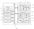
- Fig. 1 is a view illustrating an outline of a configuration of a spacecraft 1 according to a first embodiment of the present disclosure.
- the spacecraft 1 comprises a main body 300 in which a device such as a control unit controlling navigation of the spacecraft 1 itself and controlling operation and an orientation of the spacecraft 1 or the like in space is mounted, a power supply unit 200 supplying electric power for driving various constituent elements including the control unit and a communication unit 100 in space, and the communication unit 100 for emitting a radio wave from the spacecraft 1 into space in which the ground or other spacecraft exist and for receiving a radio wave from space.
- the spacecraft 1 can be used as a small synthetic aperture radar (SAR) satellite for mounting a SAR.
- SAR small synthetic aperture radar
- Such a small SAR satellite can be used for performing observation, analysis, and the like of an observation target by emitting a radio wave in a microwave band, a millimeter wave band, or sub-millimeter wave band to the observation target and then receiving the radio wave reflected from the observation target.
- an electric power amplifier needs to be mounted since high output electric power is required. Since the amplifier generates the high output power, the amplifier is very significant heat generating source.
- the spacecraft 1 is used as the small SAR satellite, it is very important how efficiently heat from the amplifier is dissipated.
- the small SAR satellite since electronic components including the amplifier need to be disposed in a limited accommodation space, it is more important to efficiently dispose the electronic components in consideration of a heat dissipation effect.
- the spacecraft 1 illustrated in Fig. 1 is used as the small SAR satellite will be described below.
- the present embodiment is not limited to the case of being used as the small SAR satellite, and can be applied to other applications, other forms (large satellite), and the like.
- the main body 300 includes an accommodation space (not illustrated) for accommodating various electronic devices and mechanical components in the main body 300.
- the main body 300 is formed by an octahedron having a hexagonal shape in a top view, and is formed in a hollow shape in order to form the accommodation space in the main body 300.
- the shape of the main body 300 may be only required to be any shape capable of forming the accommodation space in the main body 300 and may be any other shape of a polyhedron or a sphere. Additionally, a case where the main body 300 is formed in an octahedral shape having a hexagonal shape in a top view will be described below.
- Various electronic components such as a computer 301, a sensor 330, an actuator 340, a power supply control circuit 201, a battery 220, and a communication control circuit 170, and wirings for electrically connecting them are accommodated in the accommodation space formed in the main body 300.
- the power supply unit 200 includes a solar panel 230 in the present embodiment.
- the solar panel 230 is disposed on a wall surface of the main body 300 so as to cover an outer surface of the main body 300. With such an arrangement, it is possible to effectively utilize the wall surface of the main body 300.
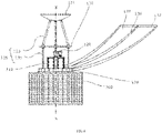
- the communication unit 100 includes a radiator 120, a subreflector (sub reflection mirror) 131 that is disposed to face the radiator 120 at a predetermined angle and reflects a radio wave emitted from the radiator 120 to a main reflector 132, the main reflector 132 that is a main reflection mirror, disposed to face a mirror surface of the subreflector 131 and further reflects the radio wave reflected by the subreflector 131 to emit the radio wave to the outside, and a support rod 135 that supports the subreflector 131.
- a subreflector (sub reflection mirror) 131 that is disposed to face the radiator 120 at a predetermined angle and reflects a radio wave emitted from the radiator 120 to a main reflector 132
- the main reflector 132 that is a main reflection mirror, disposed to face a mirror surface of the subreflector 131 and further reflects the radio wave reflected by the subreflector 131 to emit the radio wave to the outside
- a support rod 135 that supports the
- the main reflector 132 includes a hub 139, a plurality of ribs 136, a planar body 137, and the like.
- a reflection surface of the main reflector 132 is formed in a parabolic shape in order to function as the main reflection mirror as described above.
- the hub 139 is disposed on an antenna axis X (also referred to as a central axis X of the hub 139) at a center of the main reflector 132 and on a side on which the subreflector 131 of the main body 300 is disposed.
- the hub 139 is formed in a substantially columnar shape and formed of a dielectric such as plastic or a metal such as titanium or stainless.
- the hub 139 has a central axis X as a center, and a plurality of the ribs 136 are radially arranged at predetermined intervals on an outer circumferential surface of the hub 139. That is, a cross sectional shape of the hub 139 (cross sectional shape when viewed from a direction along the central axis X) is circular, but the shape may be formed in either an elliptical shape or a polygonal shape.
- the rib 136 includes a plurality of ribs. Each of the ribs 136 is radially arranged on an outer circumference of the hub 139 at predetermined intervals around the hub 139. An upper surface of each of the ribs 136 on a side serving as a reflection mirror surface is formed in a parabolic shape. The planar body 137 is provided on the upper surface formed in the parabolic shape.
- the rib 136 is a spring member formed of stainless spring steel or a composite material such as glass fiber reinforced plastics (GFRP) or carbon fiber reinforced plastics (CFRP), and has elasticity.
- the rib 136 includes a total of 24 ribs.
- the number of the ribs 136 can be changed, regardless of an even number or an odd number, according to an area of the deployable antenna at the time of deployment, a material and strength of the ribs to be used, and the like.
- the ribs 136 are disposed at predetermined intervals. However, all of the ribs 136 may be disposed at constant intervals, and may be disposed at partially dense intervals, or may be disposed at irregular intervals.
- the planar body 137 forming the main reflector 132 together with the ribs 136 is provided between a pair of the ribs 136 adjacent to each other.
- the planar body 137 is formed of a material capable of reflecting the radio wave and has a parabolic shape as a whole.
- the planar body 137 is formed by a metal network (metal mesh) formed of molybdenum, gold, or a combination thereof.
- metal mesh metal network
- substantially triangular metal meshes are prepared according to the number of the ribs 136, and the metal meshes are coupled to be provided on upper surfaces of the ribs 136 formed in the parabolic shape.
- the subreflector 131 is disposed to face the main reflector 132, and a lower surface side of the subreflector 131 (side corresponding to the main reflector 132) is supported by the support rod 135.
- the subreflector 131 is disposed to be spaced from the radiator 120 disposed on a line of the central axis X by a predetermined distance with the support rod 135.
- the subreflector 131 is made of a material capable of reflecting the radio wave and has a quadratic surface shape as a whole toward the surface of the main reflector 132.
- the subreflector 131 reflects the radio wave radiated from the radiator 120 toward the main reflector 132. Therefore, the subreflector 131 is disposed to be spaced from the radiator 120 and the main reflector 132 by a predetermined distance.
- the support rod 135 is disposed in order to dispose the subreflector 131 to be spaced from the radiator 120 and the main reflector 132 by a predetermined distance.
- the support rod 135 includes a first support rod 133 having one end connected to the subreflector 131 and the other end connected to a joint 138, and a second support rod 134 having one end connected to the joint 138 and the other end connected to the main body.
- the subreflector 131 connected to one end of the first support rod 133 is supported by the first support rod 133 and the second support rod 134.
- the support rod 135 includes one or more rods to support the subreflector 131. In the example of Fig.
- first support rod 133 and the second support rod 134 form a pair.
- the present disclosure is not limited to this, and the number of the second support rods 134 may be reduced or increased with respect to the first support rod 133.
- the spacecraft 1 a small SAR satellite having a Cassegrain antenna of which the main reflector 132 is formed in a parabolic shape will be described.
- the present disclosure is not limited to this, and other parabolic antennas such as a Gregorian antenna or a planar antenna may be provided.
- Fig. 2 is a block diagram illustrating a configuration of the spacecraft 1 according to the first embodiment of the present disclosure.
- the spacecraft 1 does not need to comprise all of the constituent elements illustrated in Fig. 2 , and can have a configuration in which a part of the spacecraft 1 is omitted, or other constituent elements can be added.
- the spacecraft 1 can also be provided with a plurality of the power supply units 200 and/or a plurality of the communication units 100.
- the spacecraft 1 comprises a control unit including a memory 310, a processor 320, and a sensor 330, the power supply unit 200 including a power supply control circuit 210, the battery 220, and the solar panel 230, and the communication unit 100 including the communication control circuit 170, the transmitter 110, a receiver 140, the radiator 120, and a reflection unit 130.
- the control unit including a memory 310, a processor 320, and a sensor 330
- the power supply unit 200 including a power supply control circuit 210, the battery 220, and the solar panel 230
- the communication unit 100 including the communication control circuit 170, the transmitter 110, a receiver 140, the radiator 120, and a reflection unit 130.
- the memory 310 includes a RAM, a ROM, a nonvolatile memory, an HDD, and the like, and functions as a storage unit.
- the memory 310 stores, as a program, instruction commands for controlling the spacecraft 1 according to the present embodiment in various manners.
- the memory 310 appropriately stores an image of an outside of the spacecraft 1, which is captured by a camera (not illustrated), an observation value obtained by using the communication unit 100 as a radar, information received from the ground station via the communication unit 100 or information transmitted to the ground station via the communication unit 100, detection information obtained by the sensor 330 necessary for controlling the orientation and travel of the spacecraft 1, and the like.
- the processor 320 functions as the control unit that controls the spacecraft 1 based on the program stored in the memory 310. Specifically, the power supply unit 200, the communication unit 100, the sensor 330, and the like are controlled based on the program stored in the memory 310. As an example, generation of information for performing transmission to the ground station or other spacecraft via the communication unit 100, and control related to the observation performed by emitting the radio wave to an observation target to receive the radio wave reflected from the observation target by using the communication unit 100 as a radar are performed.
- the sensor 330 can include a gyro sensor, an acceleration sensor, a position sensor, a velocity sensor, a fixed star sensor, and the like, which are necessary for controlling the travel and orientation of the spacecraft 1, a temperature sensor, an illuminance sensor, an infrared sensor, and the like, which are for observing an external environment of the spacecraft 1, and a temperature sensor and an illuminance sensor, and the like, which are for measuring an internal environment of the spacecraft 1.
- the detected information and data are appropriately stored in the memory 310, used for control by the processor 320, and transmitted to a base station on the ground via the communication unit 100.
- the actuator 340 can include, for example, a magnetic torquer, a reaction wheel, a control moment gyro (CMG), and the like.
- the actuator 340 is used to obtain torque and thrust for controlling the orientation of the spacecraft 1 in response to an instruction command from the processor 320, and functions as a propulsion unit.
- the power supply unit 200 includes the power supply control circuit 210, the battery 220, and the solar panel 230, and functions as a power supply unit.
- the power supply control circuit 210 is connected to the battery 220 and controls charging and discharging of electric power of the battery 220. Under the control by the power supply control circuit 210, the battery 220 charges electric power generated by the solar panel 230 and accumulates the electric power to be supplied to each of drive systems such as the computer 301 and the communication unit 100 in the main body 300.
- the communication unit 100 includes the communication control circuit 170, the transmitter 110, the receiver 140, the radiator 120, and the reflection unit 130, and functions as a communication unit.
- the communication control circuit 170 performs processing such as encoding/decoding of information and signals in order to transmit and receive information to and from the ground station or other spacecraft via the radiator 120 connected to the communication control circuit 170.
- the transmitter 110 includes an oscillator, an amplifier, and the like, and amplifies a radio wave having a frequency of a predetermined frequency band, which is generated by the oscillator, with the amplifier. The amplified radio wave is emitted to the reflection surface of the reflection unit 130 via the radiator 120.
- the communication unit 100 is used for performing the observation by using the radio wave emitted to the observation target and reflected from the observation target. Accordingly, the radio wave emitted from the radiator 120 is once reflected by the subreflector 131 forming the reflection unit 130 and emitted to the outside by the main reflector 132. On the other hand, the reflected radio wave received from the outside is received by the receiver 140 through a reverse path.
- the communication unit 100 can adjust a frequency of a microwave band such as a frequency band of 8 GHz or less, an 8 GHz to 12 GHz band (so-called X band), and a 12 GHz to 18 GHz band (so-called Ku band), a frequency of a millimeter wave band of 30 GHz or more, a frequency of a sub-millimeter wave band of 300 GHz or more, and the like as desired.
- Fig. 3 is a block diagram illustrating a configuration of the transmitter 110 according to the first embodiment of the present disclosure. Specifically, Fig. 3 is a diagram functionally illustrating an internal configuration of the transmitter 110 illustrated in Fig. 2 . According to Fig. 3 , the transmitter 110 includes an oscillator 111, an amplifier 112, a synthesizer 113, and a low-pass filter 114.
- the oscillator 111 is disposed inside the main body 300 in Fig. 1 .
- the oscillator 111 outputs a high frequency signal serving as a radio wave for transmitting a signal or the like.
- the oscillator 111 outputs a radio wave including at least any of frequencies of a microwave band such as a frequency band of 8 GHz or less, an 8 GHz to 12 GHz band (so-called X band), and a 12 GHz to 18 GHz band (so-called Ku band), a frequency of a millimeter wave band of 30 GHz or more, or a frequency of a submillimeter wave band of 300 GHz or more, preferably at least any of frequencies of a microwave band such as frequency band of 8 GHz or less, an 8 GHz to 12 GHz band (so-called X band), and a 12 GHz to 18 GHz band (so-called Ku band), and more preferably at least any of frequencies of an 8 GHz to 12 GHz band (so-called X band), and
- the amplifier 112 is electrically connected to the oscillator 111 and amplifies electric power of the radio wave output from the oscillator 111.
- data of the observation target is observed by emitting a radio wave toward the observation target and receiving the radio wave reflected from the observation target. Therefore, significantly high transmit electric power is required.
- the amplifier 112 amplifies the transmit electric power so as to be 500 W to 5,000 W, preferably 700 W to 2,500W, and more preferably 1,000 W to 1,500 W.
- the amplifier 112 can be configured by combining one or more amplifiers in accordance with output capability of the amplifier. A specific configuration of the amplifier 112 will be described later. Additionally, the output capability of the amplifier is merely an example.
- an upper limit and a lower limit of each range merely define the electric power required at the present time, and it is possible to obtain a desired effect such as a heat dissipation effect by applying the configuration according to the present embodiment as a matter of course even when the output capability exceeds the upper limit or the output capability is lower than the lower limit.
- the synthesizer 113 is electrically connected to the amplifier 112 and synthesizes the radio waves output from the respective amplifiers into one carrier wave.
- the low-pass filter 114 is electrically connected to the synthesizer 113, and is used to extract only a low-frequency component from the radio wave output from the synthesizer 113 and remove the low-frequency component. For example, this is for removing the radio wave of a frequency band, of which use is restricted by the Radio Act.
- the radio wave which has passed through the low-pass filter 114 is output to the radiator 120 illustrated in Fig. 2 and emitted to the outside via the radiator 120.
- the amplifier 112 included in the transmitter 110 a high output electric power amplifier is used as described above. Therefore, the amplifier 112 dissipates heat when operating, and adversely affects surrounding electronic devices. Moreover, when a temperature of the amplifier 112 is high, risk such as the damage of the element itself constituting the amplifier 112 is increased. Accordingly, in the present embodiment, the amplifier 112 is disposed on an exterior portion of the main body 300 and exposed to space. In this configuration, the amplifier 112 can be isolated from other electronic devices such as the processor 320, which are accommodated in the accommodation space inside the main body 300, and adverse effects on other electronic devices can be reduced. Furthermore, in a case where the spacecraft 1 is going around a satellite orbit, it is also possible to efficiently cool the amplifier 112 by exposing the amplifier 112 to space.
- Fig. 4 is a side view illustrating an outline of a configuration of the spacecraft 1 according to the first embodiment of the present disclosure. Specifically, Fig. 4 is a view in which a partial configuration of the main reflector 132 is omitted in order to illustrate the arrangement position of the amplifier 112. Furthermore, Fig. 5 is a top view illustrating an outline of a configuration of the spacecraft 1 according to the first embodiment of the present disclosure. Specifically, Fig. 5 is a view in which a partial configuration of the subreflector 131 is omitted in order to illustrate the arrangement position of the amplifier 112.
- the hub 139 which is formed in a substantially columnar shape and on which the ribs 136 forming the main reflector 132 are radially disposed at equal intervals on the outer circumference, is disposed.
- the hub 139 has, as an example, a substantially circular shape when viewed from a direction along the central axis X in cross section.
- the amplifier 112 is disposed at a substantially central position of the hub 139 formed in a circular shape and on the same surface (that is, the upper surface) as the main body 300 on which the hub 139 is disposed. Therefore, the amplifier 112 is not accommodated in the accommodation space inside the main body 300, but is disposed on a surface exposed to space.
- the radiator 120 is of course not limited to this configuration, but is configured as a horn type radiator as an example.
- the subreflector 131 is disposed to be spaced from the horn type radiator 120 by a predetermined interval by using the support rod 135 including the first support rod 133, the second support rod 134, and the joint 138.
- the amplifier 112 is disposed at a position close to the radiator 120 and on a line (that is, on the line of the central axis X) connecting the radiator 120 with the subreflector 131.
- the arrangement positions of the amplifier 112 and the radiator 120 are merely examples, and may not be disposed on the line of the central axis X as a matter of course.
- the radio wave amplified by the amplifier 112 is electrically transmitted via a coaxial cable and/or a waveguide until reaching the radiator 120 via various electronic components electrically connected to each other.
- electric power loss occurs when the radio wave passes through each electronic component and the coaxial cable, and the transmission efficiency thereof is reduced. Therefore, as in the present embodiment, by disposing the amplifier 112 at a position close to the radiator 120 and on a line (that is, on the line of the central axis X) connecting the radiator 120 with the subreflector 131, it is possible to minimize a wiring distance by using the coaxial cable and/or the waveguide, and to reduce the electric power loss.
- the hub 139 is formed in a substantially circular shape in a top view, and is disposed on the upper surface of the main body 300 formed in a hexagonal shape. Furthermore, the center of the hub 139 is disposed so as to pass through the central axis X. On the outer circumferential surface of the hub 139, a plurality of the ribs 136 forming the main reflector 132 are disposed at equal intervals. In the present embodiment, it is not illustrated in Fig. 5 , but the subreflector 131 is disposed so that the center of the subreflector 131 is positioned on the central axis X of the hub 139. Therefore, the radiator 120 that emits the radio wave to the subreflector 131 is also disposed on the central axis of the hub 139.
- the amplifier 112 is disposed on the upper surface of the main body 300 formed in a hexagonal shape and immediately below the radiator 120 for the purpose of reducing the wiring distance to the radiator 120. Therefore, the amplifier 112 is disposed so as to be positioned substantially at the center of the hub 139.
- Fig. 5 is a top view illustrating an outline of a configuration of the spacecraft 1 according to the first embodiment of the present disclosure.
- Fig. 6 is a side view illustrating an outline of a configuration of the amplifier 112 according to the first embodiment of the present disclosure.
- the amplifier 112 includes four amplifiers 112-1a to 112-1d.
- the four amplifiers 112-1a to 112-1d are disposed so as to form side surfaces of a rectangular parallelepiped respectively.
- These amplifiers 112-1a to 112-1d are supported by a frame 112-2 disposed so as to connect the amplifiers. That is, it is not illustrated in Figs.
- the amplifiers 112-1a to 112-1d are fixed to the upper surface of the main body 300 via the frame 112-2.
- the four amplifiers are disposed so as to form the side surfaces of the rectangular parallelepiped, but the number of amplifiers to be used may be one or plural other than four. It is possible to appropriately adjust the number of amplifiers in accordance with the desired electric power.
- This coating can be formed by any method as necessary, such as sticking a coating material formed in a sheet shape or spraying a coating agent formed in a liquid state.
- only the surface exposed to space is coated, but the present disclosure is not limited to this, and the upper surface or the inner surface may be coated.
- the four amplifiers 112-1a to 112-1d are connected to the synthesizer 113 by a coaxial cable and/or a waveguide (not illustrated) having one end connected to each of the amplifiers 112-1a to 112-1d and the other end connected to the synthesizer 113.
- the radio waves power-amplified by the amplifiers 112-1a to 112-1d are synthesized by the synthesizer 113.
- the horn type radiator 120 is disposed on the central axis X which is a center of the amplifiers 112-1a to 112-1d disposed so as to form the side surfaces of the rectangular parallelepiped.
- the synthesizer 113 and the radiator 120 are disposed on the upper surface side of the main body 300 by the frame 112-2 together with the amplifiers 112-1a to 112-1d.
- the other communication unit 180 is adjacent to the radiator 120, and also fixed to the frame 112-2.
- the communication unit 180 includes the horn type radiator, and is used, for example, for communication in a frequency band of 12 GHz to 18 GHz band (so-called Ku band) used for data transmission from the spacecraft 1 to the ground station.
- a frequency band of 12 GHz to 18 GHz band such as “so-called Ku band
- the communication unit 180 includes, for example, only a low power amplifier.
- the amplifier 112 is disposed on the surface of the main body 300 exposed to space. According to this, not only the heat dissipation effect of the heat generated by the amplifier 112 can be enhanced, but also the amplifier 112 which is a heat generating source can be isolated from other electronic devices, so that the adverse effect can be reduced. Furthermore, by enhancing the heat dissipation effect of the amplifier 112, the risk such as the damage of the element itself constituting the amplifier 112 can be reduced. Moreover, particularly in the small SAR satellite, the limited accommodation space of the main body 300 can be effectively used.
- the amplifier 112 is disposed on the antenna arrangement surface side of the main body 300.
- the present disclosure is not limited to this, and the amplifier 112 can be disposed on the other surface of the main body 300.
- the communication unit 100 having a so-called Cassegrain antenna having the subreflector 131 in addition to the main reflector 132 has been described.
- the present disclosure is not limited to the communication unit 100, and the communication unit may be a Gregorian type communication unit, a communication unit having a parabolic shape that emits a radio wave from a front surface of the reflector 121, or a communication unit having a planar antenna.
Landscapes
- Engineering & Computer Science (AREA)
- Remote Sensing (AREA)
- Physics & Mathematics (AREA)
- General Physics & Mathematics (AREA)
- Radar, Positioning & Navigation (AREA)
- Aviation & Aerospace Engineering (AREA)
- Astronomy & Astrophysics (AREA)
- Computer Networks & Wireless Communication (AREA)
- Electromagnetism (AREA)
- Chemical & Material Sciences (AREA)
- Combustion & Propulsion (AREA)
- Evolutionary Computation (AREA)
- Aerials With Secondary Devices (AREA)
- Details Of Aerials (AREA)
Applications Claiming Priority (1)
| Application Number | Priority Date | Filing Date | Title |
|---|---|---|---|
| PCT/JP2019/043256 WO2021090361A1 (ja) | 2019-11-05 | 2019-11-05 | 宇宙航行体 |
Publications (4)
| Publication Number | Publication Date |
|---|---|
| EP4074607A1 true EP4074607A1 (de) | 2022-10-19 |
| EP4074607A4 EP4074607A4 (de) | 2023-07-12 |
| EP4074607B1 EP4074607B1 (de) | 2025-04-30 |
| EP4074607C0 EP4074607C0 (de) | 2025-04-30 |
Family
ID=75849672
Family Applications (1)
| Application Number | Title | Priority Date | Filing Date |
|---|---|---|---|
| EP19951309.4A Active EP4074607B1 (de) | 2019-11-05 | 2019-11-05 | Raumfahrzeug |
Country Status (5)
| Country | Link |
|---|---|
| US (1) | US12187459B2 (de) |
| EP (1) | EP4074607B1 (de) |
| JP (1) | JP7179197B2 (de) |
| CN (1) | CN114599587B (de) |
| WO (1) | WO2021090361A1 (de) |
Families Citing this family (1)
| Publication number | Priority date | Publication date | Assignee | Title |
|---|---|---|---|---|
| CN116443273B (zh) * | 2023-03-13 | 2025-06-17 | 北京临近空间飞行器系统工程研究所 | 一种基于在轨飞行的航天电子综合通用处理器及方法 |
Family Cites Families (80)
| Publication number | Priority date | Publication date | Assignee | Title |
|---|---|---|---|---|
| JPS4934356B1 (de) * | 1969-10-01 | 1974-09-13 | ||
| US3716869A (en) * | 1970-12-02 | 1973-02-13 | Nasa | Millimeter wave antenna system |
| FR2517626A1 (fr) * | 1981-12-04 | 1983-06-10 | Europ Agence Spatiale | Engin spatial orbital, notamment satellite, a missions multiples |
| JPS60149500A (ja) * | 1984-01-17 | 1985-08-06 | 株式会社セブンシ−ズ | 表示用合体製品 |
| JPS60149500U (ja) * | 1984-03-16 | 1985-10-04 | 株式会社東芝 | 人工衛星の熱シ−ルド装置 |
| DE3631735A1 (de) * | 1986-09-18 | 1988-04-07 | Messerschmitt Boelkow Blohm | Nachrichtenuebertragungseinrichtung fuer raumfahrzeuge |
| NO175510C (no) * | 1987-03-24 | 1994-10-19 | Mitsubishi Electric Corp | Signalnivåforsterker for höyfrekvenssignaler |
| JPH02176489A (ja) * | 1988-12-27 | 1990-07-09 | Nec Corp | 飛翔体搭載用合成開口レーダ |
| FR2659501B1 (fr) * | 1990-03-09 | 1992-07-31 | Alcatel Espace | Systeme d'antenne imprimee active a haut rendement pour radar spatial agile. |
| JPH07106851A (ja) * | 1993-10-06 | 1995-04-21 | Tokai Rika Co Ltd | 発振回路 |
| US5916668A (en) * | 1995-12-22 | 1999-06-29 | Hughes Electronics Corporation | Sunshield film transparent to radio frequency energy and shielded articles |
| US5870063A (en) | 1996-03-26 | 1999-02-09 | Lockheed Martin Corp. | Spacecraft with modular communication payload |
| JPH11251824A (ja) * | 1998-03-04 | 1999-09-17 | Sumitomo Electric Ind Ltd | 走査アンテナおよびそれを用いた無線通信システム |
| US9130651B2 (en) * | 2010-08-07 | 2015-09-08 | Joseph Akwo Tabe | Mega communication and media apparatus configured to provide faster data transmission speed and to generate electrical energy |
| US9237211B2 (en) * | 2010-08-07 | 2016-01-12 | Joseph Akwo Tabe | Energy harvesting mega communication device and media apparatus configured with apparatus for boosting signal reception |
| RU2161109C1 (ru) * | 1999-09-10 | 2000-12-27 | Институт Машиноведения им. А.А. Благонравова РАН | Способ подавления помех от колебаний упругой конструкции космической трансформируемой антенны в процессе эксплуатации и устройство для его осуществления |
| US6268835B1 (en) * | 2000-01-07 | 2001-07-31 | Trw Inc. | Deployable phased array of reflectors and method of operation |
| JP2002223094A (ja) * | 2001-01-25 | 2002-08-09 | Yokohama Rubber Co Ltd:The | 電波吸収体の構造 |
| JP2002329995A (ja) * | 2001-05-07 | 2002-11-15 | Shin Etsu Chem Co Ltd | 電磁波吸収体 |
| US6933062B2 (en) * | 2001-08-16 | 2005-08-23 | General Electric Company | Article having an improved platinum-aluminum-hafnium protective coating |
| US20030164427A1 (en) * | 2001-09-18 | 2003-09-04 | Glatkowski Paul J. | ESD coatings for use with spacecraft |
| US6634601B2 (en) * | 2002-01-11 | 2003-10-21 | Northrop Grumman Corporation | Attitude sensor for spacecraft |
| JP2004077399A (ja) * | 2002-08-22 | 2004-03-11 | Hitachi Ltd | ミリ波レーダ |
| JP2004312696A (ja) * | 2003-03-24 | 2004-11-04 | Hitachi Ltd | ミリ波レーダおよびその製造方法 |
| JP4153345B2 (ja) * | 2003-03-31 | 2008-09-24 | 独立行政法人科学技術振興機構 | SiC−六方晶フェライト系セラミックス複合型電磁波吸収体の製造方法 |
| JPWO2005055366A1 (ja) * | 2003-11-14 | 2007-06-28 | 株式会社日立製作所 | 車載用レーダ |
| JP4719431B2 (ja) * | 2004-06-21 | 2011-07-06 | 富士フイルム株式会社 | 六方晶フェライト磁性粉末、その製造方法および磁気記録媒体 |
| EP1883989A1 (de) * | 2005-05-20 | 2008-02-06 | EADS Astrium Limited | Thermischer steuerfilm für raumfahrzeuge |
| US7513462B1 (en) | 2005-06-08 | 2009-04-07 | Lockheed Martin Corporation | Satellite equipment mounting panel |
| KR100971096B1 (ko) * | 2005-06-09 | 2010-07-20 | 맥도널드, 디트윌러 앤드 어소시에이츠 엘티디. | 경량의 공간-피딩된 능동 위상 어레이 안테나 시스템 |
| KR20070041923A (ko) * | 2005-10-17 | 2007-04-20 | 김정선 | 구명동의용 지피에스(GPS) 단말기의 주파수 대역130dBm 주파수확장변조 복합멀티기능시스템 |
| US7324065B2 (en) * | 2006-01-17 | 2008-01-29 | The United States Of America As Represented By The Secretary Of The Air Force | Antenna radiation collimator structure |
| JP4859791B2 (ja) * | 2006-09-01 | 2012-01-25 | 国立大学法人 東京大学 | 電波吸収材料用の磁性結晶および電波吸収体 |
| JP4876941B2 (ja) * | 2007-01-31 | 2012-02-15 | 三菱電機株式会社 | 展開型アンテナ |
| US8016240B2 (en) * | 2007-03-29 | 2011-09-13 | The Boeing Company | Satellites and satellite fleet implementation methods and apparatus |
| JP5085595B2 (ja) * | 2008-09-08 | 2012-11-28 | 株式会社東芝 | コアシェル型磁性材料、コアシェル型磁性材料の製造方法、デバイス装置、およびアンテナ装置。 |
| US8248298B2 (en) * | 2008-10-31 | 2012-08-21 | First Rf Corporation | Orthogonal linear transmit receive array radar |
| US8072380B2 (en) * | 2009-04-10 | 2011-12-06 | Raytheon Company | Wireless power transmission system and method |
| KR101045809B1 (ko) * | 2009-05-25 | 2011-07-04 | (주)하이게인안테나 | 3중 대역 위성통신용 추적 안테나장치 |
| EP2447965B1 (de) * | 2009-06-24 | 2020-01-15 | The University of Tokyo | Verfahren zur herstellung einer magnetischen dünnschicht |
| WO2011001831A1 (ja) * | 2009-06-30 | 2011-01-06 | 日立金属株式会社 | フェライト焼結磁石の製造方法及びフェライト焼結磁石 |
| WO2011105359A1 (ja) * | 2010-02-24 | 2011-09-01 | 住友電気工業株式会社 | 増幅装置、信号処理装置、無線通信装置、コネクタ取付構造、及び同軸コネクタ |
| US9929475B2 (en) * | 2010-05-10 | 2018-03-27 | Korea Institute Of Machinery & Materials | Waveband electromagnetic wave absorber and method for manufacturing same |
| JP5659905B2 (ja) | 2011-03-29 | 2015-01-28 | 日本電気株式会社 | 衛星搭載用マイクロ波送信装置、該装置を用いる目標地域の追尾方法、及び制御プログラム |
| US9743357B2 (en) * | 2011-12-16 | 2017-08-22 | Joseph Akwo Tabe | Energy harvesting computer device in association with a communication device configured with apparatus for boosting signal reception |
| US20130201316A1 (en) * | 2012-01-09 | 2013-08-08 | May Patents Ltd. | System and method for server based control |
| CN102717902B (zh) * | 2012-06-26 | 2014-12-10 | 上海卫星工程研究所 | 火星探测深空航天器的分阶段多码率自适应测控系统 |
| JP5762453B2 (ja) * | 2012-09-28 | 2015-08-12 | 富士フイルム株式会社 | 六方晶フェライト磁性粒子の製造方法およびこれにより得られた六方晶フェライト磁性粒子、ならびにそれらの利用 |
| US10732276B2 (en) * | 2013-10-21 | 2020-08-04 | Sony Corporation | Security system, method and device |
| JP5978201B2 (ja) * | 2013-12-27 | 2016-08-24 | 富士フイルム株式会社 | 磁気記録用磁性粉、磁気記録媒体、および磁気記録用磁性粉の製造方法 |
| US9519273B2 (en) * | 2014-03-06 | 2016-12-13 | Seiko Epson Corporation | Electronic timepiece and movement |
| US9483029B2 (en) * | 2014-03-06 | 2016-11-01 | Seiko Epson Corporation | Timepiece and electronic timepiece |
| WO2016079945A1 (ja) | 2014-11-18 | 2016-05-26 | 川崎重工業株式会社 | レーダ衛星およびこれを用いたレーダ衛星システム |
| JP6010181B2 (ja) * | 2015-01-09 | 2016-10-19 | Dowaエレクトロニクス株式会社 | 鉄系酸化物磁性粒子粉およびその製造方法並びに塗料および磁気記録媒体 |
| TWI666661B (zh) * | 2015-01-22 | 2019-07-21 | 日商保德科技股份有限公司 | 六角板狀鐵氧體粉末及其製造方法,以及使用該鐵氧體粉末的樹脂組合物及成型體 |
| US10583940B2 (en) * | 2015-03-03 | 2020-03-10 | York Space Systems LLC | Pressurized payload compartment and mission agnostic space vehicle including the same |
| US10170843B2 (en) * | 2015-05-29 | 2019-01-01 | California Institute Of Technology | Parabolic deployable antenna |
| WO2017018407A1 (ja) * | 2015-07-27 | 2017-02-02 | Dowaエレクトロニクス株式会社 | 鉄系酸化物磁性粒子粉の製造方法 |
| CN108370654B (zh) * | 2015-12-25 | 2020-02-07 | 日本瑞翁株式会社 | 电磁波吸收材料及电磁波吸收体 |
| US11255663B2 (en) * | 2016-03-04 | 2022-02-22 | May Patents Ltd. | Method and apparatus for cooperative usage of multiple distance meters |
| JP6113351B1 (ja) * | 2016-03-25 | 2017-04-12 | 富士高分子工業株式会社 | 磁気粘弾性エラストマー組成物、その製造方法及びこれを組み込んだ振動吸収装置 |
| EP3435386B1 (de) * | 2016-03-25 | 2021-06-02 | National Institute of Advanced Industrial Science and Technology | Magnetisches material und herstellungsverfahren dafür |
| WO2017221992A1 (ja) * | 2016-06-22 | 2017-12-28 | 日立マクセル株式会社 | 電波吸収シート |
| JP7033071B2 (ja) * | 2016-09-30 | 2022-03-09 | Dowaエレクトロニクス株式会社 | イプシロン型鉄酸化物磁性粒子及びその製造方法、磁性粒子から構成される磁性粉ならびに磁性塗料および磁気記録媒体 |
| US10938105B2 (en) * | 2016-10-21 | 2021-03-02 | Anderson Contract Engineering, Inc. | Conformal multi-band antenna structure |
| WO2018084234A1 (ja) * | 2016-11-04 | 2018-05-11 | マクセルホールディングス株式会社 | 電磁波吸収シート |
| US10670710B2 (en) * | 2016-12-06 | 2020-06-02 | Ursa Space Systems, Inc. | High efficiency synthetic aperture radar satellite |
| US10461435B2 (en) * | 2016-12-29 | 2019-10-29 | Tionesta, Llc | Multiple tuned Fresnel zone plate reflector antenna |
| US10686251B2 (en) * | 2017-01-23 | 2020-06-16 | The Boeing Company | Wideband beam broadening for phased array antenna systems |
| JP6492114B2 (ja) * | 2017-03-03 | 2019-03-27 | 日東電工株式会社 | 電磁波吸収体及び電磁波吸収体付成形品 |
| EP3598862B1 (de) * | 2017-03-13 | 2025-05-07 | Maxell, Ltd. | Elektromagnetische wellenabsorptionsschicht |
| US10116051B2 (en) * | 2017-03-17 | 2018-10-30 | Isotropic Systems Ltd. | Lens antenna system |
| US10985833B2 (en) * | 2017-04-10 | 2021-04-20 | Viasat, Inc. | Coverage area adjustment to adapt satellite communications |
| CN107146949B (zh) * | 2017-06-23 | 2023-12-08 | 广州市易恒通信科技有限公司 | 提高正馈式双反射抛物面天线接收和发射效率的卫星天线 |
| JP7216360B2 (ja) * | 2017-06-30 | 2023-02-01 | 国立大学法人 東京大学 | 電波吸収体 |
| EP3657922B1 (de) * | 2017-07-20 | 2026-01-14 | Maxell, Ltd. | Elektromagnetische wellen absorbierende zusammensetzung und körper zur absorption elektromagnetischer wellen |
| US20190058242A1 (en) * | 2017-08-21 | 2019-02-21 | Joseph Akwo Tabe | Energy harvesting substrate network and communication apparatus |
| US10670711B2 (en) * | 2017-09-29 | 2020-06-02 | Planet Labs Inc. | Systems for synthetic aperture radar transmit and receive antennas |
| JP6524356B1 (ja) * | 2017-10-19 | 2019-06-05 | 関西ペイント株式会社 | ミリ波帯域用電波吸収シート及びミリ波電波吸収方法 |
| WO2020213135A1 (ja) * | 2019-04-18 | 2020-10-22 | 株式会社Qps研究所 | アンテナ装置及び宇宙航行体 |
-
2019
- 2019-11-05 JP JP2021554436A patent/JP7179197B2/ja active Active
- 2019-11-05 CN CN201980101643.6A patent/CN114599587B/zh active Active
- 2019-11-05 US US17/773,011 patent/US12187459B2/en active Active
- 2019-11-05 EP EP19951309.4A patent/EP4074607B1/de active Active
- 2019-11-05 WO PCT/JP2019/043256 patent/WO2021090361A1/ja not_active Ceased
Also Published As
| Publication number | Publication date |
|---|---|
| JPWO2021090361A1 (de) | 2021-05-14 |
| EP4074607B1 (de) | 2025-04-30 |
| EP4074607C0 (de) | 2025-04-30 |
| US20220388691A1 (en) | 2022-12-08 |
| WO2021090361A1 (ja) | 2021-05-14 |
| JP7179197B2 (ja) | 2022-11-28 |
| CN114599587B (zh) | 2025-05-13 |
| US12187459B2 (en) | 2025-01-07 |
| EP4074607A4 (de) | 2023-07-12 |
| CN114599587A (zh) | 2022-06-07 |
Similar Documents
| Publication | Publication Date | Title |
|---|---|---|
| CA2630379C (en) | Frequency scanning antenna | |
| EP3222531B1 (de) | Radarsatellit und radarsatellitensystem mit verwendung davon | |
| US10680310B2 (en) | Balloon reflector antenna | |
| Wilden et al. | GESTRA—A phased-array based surveillance and tracking radar for space situational awareness | |
| US12187459B2 (en) | Spacecraft | |
| EP4574685A1 (de) | Raumfahrzeug | |
| Chahat et al. | Mars cube one | |
| JP7295347B2 (ja) | 接続アダプタ及びホーンアンテナ用測定装置 | |
| US11319092B2 (en) | Space vehicle, launcher and stack of space vehicles | |
| US7095377B2 (en) | Light-weight signal transmission lines and radio frequency antenna system | |
| WO2004038452A1 (en) | Adaptive antenna | |
| EP1932212B1 (de) | Frequenz-scan-antenne | |
| JPH06164231A (ja) | アンテナ装置 | |
| Sloan et al. | Affordable miniaturized SAR for tactical UAV applications | |
| Dagatti et al. | DBF Radar: A Digital Beam-Forming Radar System for Technology Research | |
| Benhmimou et al. | A Novel FR4-Based Slot Antenna with Circular Metasurface for Aerospace CubeSats | |
| Najma et al. | with Circular Metasurface for Aerospace | |
| You et al. | Spacecraft TT&C Antenna | |
| Abulgasem | High Gain Antennas for Communication between CubeSat and Ground Station | |
| Reedy et al. | Millimeter radar: current assessment, future directions | |
| Montesano et al. | Microstrip Array Technologies for Space Applications | |
| KR20260016615A (ko) | 전술적 고출력 마이크로파 안테나 페데스탈 | |
| Otten et al. | A compact mm-wave spaceborne SAR concept | |
| Álvarez et al. | Microstrip Array Technologies for Space Applications |
Legal Events
| Date | Code | Title | Description |
|---|---|---|---|
| STAA | Information on the status of an ep patent application or granted ep patent |
Free format text: STATUS: THE INTERNATIONAL PUBLICATION HAS BEEN MADE |
|
| PUAI | Public reference made under article 153(3) epc to a published international application that has entered the european phase |
Free format text: ORIGINAL CODE: 0009012 |
|
| STAA | Information on the status of an ep patent application or granted ep patent |
Free format text: STATUS: REQUEST FOR EXAMINATION WAS MADE |
|
| 17P | Request for examination filed |
Effective date: 20220324 |
|
| AK | Designated contracting states |
Kind code of ref document: A1 Designated state(s): AL AT BE BG CH CY CZ DE DK EE ES FI FR GB GR HR HU IE IS IT LI LT LU LV MC MK MT NL NO PL PT RO RS SE SI SK SM TR |
|
| DAV | Request for validation of the european patent (deleted) | ||
| DAX | Request for extension of the european patent (deleted) | ||
| A4 | Supplementary search report drawn up and despatched |
Effective date: 20230614 |
|
| RIC1 | Information provided on ipc code assigned before grant |
Ipc: G01S 7/03 20060101ALI20230607BHEP Ipc: B64G 1/10 20060101ALI20230607BHEP Ipc: B64G 1/22 20060101ALI20230607BHEP Ipc: H01Q 19/19 20060101ALI20230607BHEP Ipc: H01Q 19/13 20060101ALI20230607BHEP Ipc: B64G 1/36 20060101ALI20230607BHEP Ipc: H01Q 1/28 20060101ALI20230607BHEP Ipc: H01Q 15/16 20060101ALI20230607BHEP Ipc: G01S 7/02 20060101ALI20230607BHEP Ipc: G01S 13/90 20060101ALI20230607BHEP Ipc: B64G 1/66 20060101AFI20230607BHEP |
|
| GRAP | Despatch of communication of intention to grant a patent |
Free format text: ORIGINAL CODE: EPIDOSNIGR1 |
|
| STAA | Information on the status of an ep patent application or granted ep patent |
Free format text: STATUS: GRANT OF PATENT IS INTENDED |
|
| INTG | Intention to grant announced |
Effective date: 20241127 |
|
| GRAS | Grant fee paid |
Free format text: ORIGINAL CODE: EPIDOSNIGR3 |
|
| GRAA | (expected) grant |
Free format text: ORIGINAL CODE: 0009210 |
|
| STAA | Information on the status of an ep patent application or granted ep patent |
Free format text: STATUS: THE PATENT HAS BEEN GRANTED |
|
| AK | Designated contracting states |
Kind code of ref document: B1 Designated state(s): AL AT BE BG CH CY CZ DE DK EE ES FI FR GB GR HR HU IE IS IT LI LT LU LV MC MK MT NL NO PL PT RO RS SE SI SK SM TR |
|
| REG | Reference to a national code |
Ref country code: CH Ref legal event code: EP Ref country code: GB Ref legal event code: FG4D |
|
| REG | Reference to a national code |
Ref country code: DE Ref legal event code: R096 Ref document number: 602019069507 Country of ref document: DE |
|
| REG | Reference to a national code |
Ref country code: IE Ref legal event code: FG4D |
|
| U01 | Request for unitary effect filed |
Effective date: 20250430 |
|
| U07 | Unitary effect registered |
Designated state(s): AT BE BG DE DK EE FI FR IT LT LU LV MT NL PT RO SE SI Effective date: 20250526 |
|
| PG25 | Lapsed in a contracting state [announced via postgrant information from national office to epo] |
Ref country code: ES Free format text: LAPSE BECAUSE OF FAILURE TO SUBMIT A TRANSLATION OF THE DESCRIPTION OR TO PAY THE FEE WITHIN THE PRESCRIBED TIME-LIMIT Effective date: 20250430 |
|
| PG25 | Lapsed in a contracting state [announced via postgrant information from national office to epo] |
Ref country code: NO Free format text: LAPSE BECAUSE OF FAILURE TO SUBMIT A TRANSLATION OF THE DESCRIPTION OR TO PAY THE FEE WITHIN THE PRESCRIBED TIME-LIMIT Effective date: 20250730 Ref country code: GR Free format text: LAPSE BECAUSE OF FAILURE TO SUBMIT A TRANSLATION OF THE DESCRIPTION OR TO PAY THE FEE WITHIN THE PRESCRIBED TIME-LIMIT Effective date: 20250731 |
|
| PG25 | Lapsed in a contracting state [announced via postgrant information from national office to epo] |
Ref country code: PL Free format text: LAPSE BECAUSE OF FAILURE TO SUBMIT A TRANSLATION OF THE DESCRIPTION OR TO PAY THE FEE WITHIN THE PRESCRIBED TIME-LIMIT Effective date: 20250430 |
|
| PG25 | Lapsed in a contracting state [announced via postgrant information from national office to epo] |
Ref country code: HR Free format text: LAPSE BECAUSE OF FAILURE TO SUBMIT A TRANSLATION OF THE DESCRIPTION OR TO PAY THE FEE WITHIN THE PRESCRIBED TIME-LIMIT Effective date: 20250430 |
|
| PG25 | Lapsed in a contracting state [announced via postgrant information from national office to epo] |
Ref country code: RS Free format text: LAPSE BECAUSE OF FAILURE TO SUBMIT A TRANSLATION OF THE DESCRIPTION OR TO PAY THE FEE WITHIN THE PRESCRIBED TIME-LIMIT Effective date: 20250731 |
|
| PG25 | Lapsed in a contracting state [announced via postgrant information from national office to epo] |
Ref country code: IS Free format text: LAPSE BECAUSE OF FAILURE TO SUBMIT A TRANSLATION OF THE DESCRIPTION OR TO PAY THE FEE WITHIN THE PRESCRIBED TIME-LIMIT Effective date: 20250830 |
|
| U20 | Renewal fee for the european patent with unitary effect paid |
Year of fee payment: 7 Effective date: 20251110 |
|
| PGFP | Annual fee paid to national office [announced via postgrant information from national office to epo] |
Ref country code: GB Payment date: 20251110 Year of fee payment: 7 |
|
| PG25 | Lapsed in a contracting state [announced via postgrant information from national office to epo] |
Ref country code: SM Free format text: LAPSE BECAUSE OF FAILURE TO SUBMIT A TRANSLATION OF THE DESCRIPTION OR TO PAY THE FEE WITHIN THE PRESCRIBED TIME-LIMIT Effective date: 20250430 |
|
| PG25 | Lapsed in a contracting state [announced via postgrant information from national office to epo] |
Ref country code: CZ Free format text: LAPSE BECAUSE OF FAILURE TO SUBMIT A TRANSLATION OF THE DESCRIPTION OR TO PAY THE FEE WITHIN THE PRESCRIBED TIME-LIMIT Effective date: 20250430 |
|
| PG25 | Lapsed in a contracting state [announced via postgrant information from national office to epo] |
Ref country code: SK Free format text: LAPSE BECAUSE OF FAILURE TO SUBMIT A TRANSLATION OF THE DESCRIPTION OR TO PAY THE FEE WITHIN THE PRESCRIBED TIME-LIMIT Effective date: 20250430 |
|
| PLBE | No opposition filed within time limit |
Free format text: ORIGINAL CODE: 0009261 |
|
| STAA | Information on the status of an ep patent application or granted ep patent |
Free format text: STATUS: NO OPPOSITION FILED WITHIN TIME LIMIT |
|
| REG | Reference to a national code |
Ref country code: CH Ref legal event code: L10 Free format text: ST27 STATUS EVENT CODE: U-0-0-L10-L00 (AS PROVIDED BY THE NATIONAL OFFICE) Effective date: 20260311 |
|
| 26N | No opposition filed |
Effective date: 20260202 |