EP4574685A1 - Raumfahrzeug - Google Patents
Raumfahrzeug Download PDFInfo
- Publication number
- EP4574685A1 EP4574685A1 EP22955722.8A EP22955722A EP4574685A1 EP 4574685 A1 EP4574685 A1 EP 4574685A1 EP 22955722 A EP22955722 A EP 22955722A EP 4574685 A1 EP4574685 A1 EP 4574685A1
- Authority
- EP
- European Patent Office
- Prior art keywords
- heat radiation
- amplifier
- radiation plates
- spacecraft
- heat
- Prior art date
- Legal status (The legal status is an assumption and is not a legal conclusion. Google has not performed a legal analysis and makes no representation as to the accuracy of the status listed.)
- Pending
Links
Images

Classifications
-
- B—PERFORMING OPERATIONS; TRANSPORTING
- B64—AIRCRAFT; AVIATION; COSMONAUTICS
- B64G—COSMONAUTICS; VEHICLES OR EQUIPMENT THEREFOR
- B64G1/00—Cosmonautic vehicles
- B64G1/22—Parts of, or equipment specially adapted for fitting in or to, cosmonautic vehicles
- B64G1/46—Arrangements or adaptations of devices for control of environment or living conditions
- B64G1/50—Arrangements or adaptations of devices for control of environment or living conditions for temperature control
- B64G1/503—Radiator panels
-
- B—PERFORMING OPERATIONS; TRANSPORTING
- B64—AIRCRAFT; AVIATION; COSMONAUTICS
- B64G—COSMONAUTICS; VEHICLES OR EQUIPMENT THEREFOR
- B64G1/00—Cosmonautic vehicles
- B64G1/10—Artificial satellites; Systems of such satellites; Interplanetary vehicles
- B64G1/1021—Earth observation satellites
Definitions
- the technology disclosed in the present application relates to a mechanism in which a satellite including a synthetic aperture radar (SAR) radiates heat generated from an amplifier during SAR observation.
- SAR synthetic aperture radar
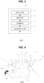
- a temperature of a first amplifier 112 (for example, the amplifier 112 arranged on the right side in Fig. 5 ) fixed to the heat radiation plate 402 irradiated with the sunlight can be higher than a temperature of a second amplifier 112 (for example, the amplifier 112 arranged on the left side in Fig. 5 ) that is arranged on the opposite side to the amplifier 112 and is difficult to be irradiated with the sunlight.
- power of a signal amplified and output by the first amplifier 112 having a higher temperature can be lower than power of a signal amplified and output by the second amplifier 112.
- power of a signal combined and output by the combiner 113 can also be lower than the originally intended power.
- the power of the signal amplified and output by the first amplifier 112 can more easily vary with the lapse of time as compared with the power of the signal amplified and output by the second amplifier 112.
- the power of the signal combined and output by the combiner 113 can also vary with the lapse of time.
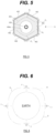
- Fig. 8 is a perspective view schematically illustrating a part of another configuration example of the spacecraft 1 illustrated in Fig. 1 .
- the heat radiation unit 400, the upper surface 30 of the body 300, and the like are illustrated in Fig. 8
- other configurations are similar to those illustrated in Fig. 1 .
- the heat radiation unit 400 can further include at least one (two in Fig. 8 as an example) first thermally conductive member 500 that is in contact with both a lower surface 404b of the top plate 404 and the side wall 402a of each heat radiation plate 402 to thermally connect the lower surface 404b and the side wall 402a to each other.
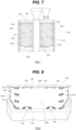
- Fig. 9 is an enlarged perspective view illustrating only the first thermally conductive member 500 and a periphery thereof illustrated in Fig. 8 .
- the first thermally conductive member 500 can have a substantially rectangular parallelepiped shape as a whole.
- the first thermally conductive member 500 can be fixed to the lower surface 404b by using a fastening member such as a bolt, a screw, or a rivet that is engaged with the first thermally conductive member 500 and the lower surface 404b in a state where one surface (for example, an upper surface) is in contact with the lower surface 404b of the top plate 404 and another surface (for example, a side surface) is in contact with the side wall 402a of the heat radiation plate 402.
- a fastening member such as a bolt, a screw, or a rivet that is engaged with the first thermally conductive member 500 and the lower surface 404b in a state where one surface (for example, an upper surface) is in contact with the lower surface 404b of the top plate
- the first thermally conductive member 500 can be integrally molded with one of (the lower surface 404b of) the top plate 404 and (the side wall 402a of) the heat radiation plate 402, and fixed to the other by using the fastening member.
- the first thermally conductive member 500 can be fixed to both of (the lower surface 404b of) the top plate 404 and (the side wall 402a of) the heat radiation plate 402 by using the fastening members.
- Such a first thermally conductive member 500 can be formed of any material including aluminum, duralumin, copper, iron, and/or steel.
- Fig. 8 illustrates an example in which two first thermally conductive members 500 are provided for one heat radiation plate 402.
- the number of first thermally conductive members 500 provided for one heat radiation plate 402 can be one or more.
- a case where sunlight traveling in the direction S 2 is incident on the radiation plate 402 is considered.
- heat generated in the radiation plate 402 (and the amplifier 112 thermally connected thereto) is transferred to the top plate 404 via the first thermally conductive member 500 provided on the radiation plate 402 (arrow F 1 ), and can propagate through the entire top plate 404 (arrow F 2 ).
- the heat propagating through the entire top plate 404 can also be transferred to each amplifier 112 via another radiation plate 402 thermally connected to the top plate 404 via the first thermally conductive member 500.
- the temperatures of all the amplifiers 112 can be equalized.
- the first thermally conductive member 500 may be a portion integrally molded with the top plate 404 (or the heat radiation plate 404) or may be a portion welded or deposited to the top plate 404 (or the heat radiation plate 404) .
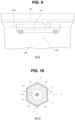
- the heat radiation unit 400 can further include, in addition to or instead of the first thermally conductive member 500, at least one second thermally conductive member 510 that thermally connects two adjacent heat radiation plates 402 among the plurality of heat radiation plates 402.
- Such a second thermally conductive member 510 can have a shape extending in a substantially V shape as a whole.
- the second thermally conductive member 510 can be fixed to the side walls 402a by using fastening members such as bolts, screws, or rivets that are engaged with the side walls 402a in a state where one surface (inner surface) is in contact with the side walls 402a of the two adjacent radiation plates 402.
- fastening members such as bolts, screws, or rivets that are engaged with the side walls 402a in a state where one surface (inner surface) is in contact with the side walls 402a of the two adjacent radiation plates 402.
- Such a second thermally conductive member 510 can be formed of any material including aluminum, duralumin, copper, iron, and/or steel.
- Fig. 8 illustrates an example in which four second thermally conductive members 510 are provided for two adjacent heat radiation plates 402.
- the number of second thermally conductive members 510 provided for two adjacent heat radiation plates 402 can be one or more.
- a case where sunlight traveling in the direction S 2 is incident on the radiation plate 402 is considered.
- heat generated in the radiation plate 402 (and the amplifier 112 thermally connected thereto) is transferred to another radiation plate 402 adjacent to the radiation plate 402 via the second thermally conductive member 510 provided on the radiation plate 402 (arrow F 3 ), and can further propagate to still another radiation plate 402 adjacent to the another radiation plate 402 via the second thermally conductive member 510 provided on the another radiation plate 402 (arrow F 4 ).
- the heat generated in the amplifier 112 thermally connected to the radiation plate 402 irradiated with sunlight can also be transferred to each of the other amplifiers 112.
- the temperatures of all the amplifiers 112 can be equalized.
- the antenna unit and the heat radiation unit 400 can be provided in association with different surfaces of the body 300.
- the antenna unit can be provided in association with the upper surface 302 of the body 300 (above the upper surface 302), and the heat radiation unit 400 may be provided in association with a lower surface 304 of the body 300 (below the lower surface 304).
- each heat radiation plate 402 is provided so as to extend substantially parallel to the reference direction D, but such a configuration is not an essential configuration and can be used as an option. That is, it is also possible to effectively radiate heat in the spacecraft 1 by using at least one of the configurations exemplified below without using the configuration.
- each heat radiation plate 402 is provided so as to extend substantially parallel to the reference direction D
- an example in which all the heat radiation plates 402 are provided so as to extend substantially parallel to the reference direction D has been described as the most preferable example.
- a spacecraft can include: "a body in which a plurality of devices including an oscillator that outputs a signal having a frequency of at least one frequency band are mounted; a plurality of heat radiation plates arranged outside the body, extending substantially parallel to a reference direction, and provided to face each other; at least one amplifier arranged in a region surrounded by the plurality of heat radiation plates, connected to any one of the plurality of heat radiation plates, and configured to amplify the signal output by the oscillator; and an antenna unit arranged outside the body and configured to radiate radio waves traveling in the reference direction by using the signal amplified by the at least one amplifier".
- the at least one amplifier is fixed to any one of the plurality of heat radiation plates at a position that is not in contact with the body.
- a configuration in which "each of the plurality of heat radiation plates is provided at a distance from the body by being fixed to the body via at least one heat insulating member having a substantially L-shaped or substantially inverted L-shaped cross-sectional shape and attached to both a side wall of the heat radiation plate and an outer surface of the body" can be adopted.
- a configuration in which "a side wall of each of the plurality of heat radiation plates is positioned at a distance from an outer edge of an outer surface of the body in a direction toward a center of the outer surface" can be adopted.
- a configuration "further including a top plate formed of a thermally conductive member that is arranged on the plurality of heat radiation plates, is thermally connected to each of the plurality of heat radiation plates, and surrounds the at least one amplifier in cooperation with the plurality of heat radiation plates" can be adopted.
- a configuration "further including at least one first thermally conductive member that is in contact with a lower surface of the top plate and a side wall of each of the plurality of heat radiation plates to thermally connect the lower surface and the side wall" can be adopted.
- a configuration "further including at least one second thermally conductive member that thermally connects two adjacent heat radiation plates among the plurality of heat radiation plates" can be adopted.
- a configuration "further including at least one support frame that is provided so as to be fixed to an outer surface of the body with at least one heat insulating member interposed therebetween, extend in a direction intersecting the outer surface, and support the at least one amplifier" can be adopted.
- the spacecraft according to the third or eighth aspect a configuration in which "the at least one heat insulating member has a thermal conductivity of 0.2 W/m ⁇ K or less" can be adopted.
- the technology disclosed in the present application it is possible to provide a spacecraft with an improved heat dissipation capability. Furthermore, according to the technology disclosed in the present application, it is possible to provide a spacecraft that can efficiently dissipate heat of a mounted high-output device. Furthermore, according to the technology disclosed in the present application, it is possible to provide a spacecraft that can improve performance (output performance or the like) and/or efficiency of a high-output device including a semiconductor device and mounted as described above by efficiently dissipating heat of the high-output device and lowering a temperature of the high-output device.
- Such a spacecraft can improve the efficiency of the high-output device including the semiconductor device, for example, by lowering an initial temperature at the start of operation of the high-output device. Furthermore, according to the technology disclosed in the present application, it is possible to provide a spacecraft that can secure a continuous operation time of a mounted high-output device by shortening a time required to dissipate heat of the high-output device while the spacecraft is orbiting the earth.
Landscapes
- Engineering & Computer Science (AREA)
- Health & Medical Sciences (AREA)
- Life Sciences & Earth Sciences (AREA)
- Biodiversity & Conservation Biology (AREA)
- Environmental & Geological Engineering (AREA)
- Environmental Sciences (AREA)
- General Health & Medical Sciences (AREA)
- Toxicology (AREA)
- Remote Sensing (AREA)
- Aviation & Aerospace Engineering (AREA)
- Details Of Aerials (AREA)
Applications Claiming Priority (1)
| Application Number | Priority Date | Filing Date | Title |
|---|---|---|---|
| PCT/JP2022/031238 WO2024038548A1 (ja) | 2022-08-18 | 2022-08-18 | 宇宙航行体 |
Publications (1)
| Publication Number | Publication Date |
|---|---|
| EP4574685A1 true EP4574685A1 (de) | 2025-06-25 |
Family
ID=87972053
Family Applications (1)
| Application Number | Title | Priority Date | Filing Date |
|---|---|---|---|
| EP22955722.8A Pending EP4574685A1 (de) | 2022-08-18 | 2022-08-18 | Raumfahrzeug |
Country Status (3)
| Country | Link |
|---|---|
| EP (1) | EP4574685A1 (de) |
| JP (1) | JP7341382B1 (de) |
| WO (1) | WO2024038548A1 (de) |
Families Citing this family (2)
| Publication number | Priority date | Publication date | Assignee | Title |
|---|---|---|---|---|
| EP4538056B1 (de) * | 2023-10-12 | 2026-04-22 | Venturi Lab SA | Verformbares rad mit nicht-pneumatischer laufstreifen und mit laufflächenheizung für bedingungen auf dem mond und mars |
| KR102727275B1 (ko) * | 2023-12-14 | 2024-11-07 | 한화시스템 주식회사 | 위성 장치 및 위성 운용 방법 |
Family Cites Families (5)
| Publication number | Priority date | Publication date | Assignee | Title |
|---|---|---|---|---|
| JPH0657800U (ja) * | 1993-01-20 | 1994-08-12 | 石川島播磨重工業株式会社 | 宇宙用放熱板の姿勢制御装置 |
| US5806803A (en) * | 1995-11-30 | 1998-09-15 | Hughes Electronics Corporation | Spacecraft radiator cooling system |
| JP3979325B2 (ja) | 2003-03-31 | 2007-09-19 | 三菱電機株式会社 | ヒートシンク |
| US7733659B2 (en) * | 2006-08-18 | 2010-06-08 | Delphi Technologies, Inc. | Lightweight audio system for automotive applications and method |
| US9868551B2 (en) * | 2015-03-30 | 2018-01-16 | Worldvu Satellites Limited | Passive thermal system comprising combined heat pipe and phase change material and satellites incorporating same |
-
2022
- 2022-08-18 EP EP22955722.8A patent/EP4574685A1/de active Pending
- 2022-08-18 WO PCT/JP2022/031238 patent/WO2024038548A1/ja not_active Ceased
- 2022-08-18 JP JP2023547282A patent/JP7341382B1/ja active Active
Also Published As
| Publication number | Publication date |
|---|---|
| JP7341382B1 (ja) | 2023-09-15 |
| WO2024038548A1 (ja) | 2024-02-22 |
| JPWO2024038548A1 (de) | 2024-02-22 |
Similar Documents
| Publication | Publication Date | Title |
|---|---|---|
| CN107848635B (zh) | 具有组合加强片/热管的卫星辐射器面板 | |
| US11381006B2 (en) | Integrated tracking antenna array | |
| EP4574685A1 (de) | Raumfahrzeug | |
| US10793297B2 (en) | Passive thermal system comprising combined heat pipe and phase change material and satellites incorporating same | |
| US11009297B2 (en) | Fluidicially coupled heat pipes and method therefor | |
| US7692593B2 (en) | Generic pick-up horn for high power thermal vacuum testing of satellite payloads at multiple frequency bands and at multiple polarizations | |
| US9038960B2 (en) | Absorbent dome for a radiating collector tube | |
| EP3089912B1 (de) | Telekommunikationssatellitenarchitektur | |
| US7762499B1 (en) | Independent East/West thermal management system | |
| US9908643B2 (en) | Passive thermal system providing an embedded interface for heat pipes | |
| US11319092B2 (en) | Space vehicle, launcher and stack of space vehicles | |
| CN117644996B (zh) | 一种光学卫星 | |
| US12187459B2 (en) | Spacecraft | |
| JP5665028B2 (ja) | 送信アンテナ | |
| JP2013233906A (ja) | 宇宙機 | |
| US7598919B2 (en) | Pick-up horn for high power thermal vacuum testing of spacecraft payloads | |
| US12489197B1 (en) | Systems and methods for satellite thermal management | |
| Saito et al. | Compact X-band Synthetic Aperture Radar with Deployable Plane Antenna and RF Feeding System through Non-contact Waveguides-Project of a 100kg-class SAR Satellite |
Legal Events
| Date | Code | Title | Description |
|---|---|---|---|
| STAA | Information on the status of an ep patent application or granted ep patent |
Free format text: STATUS: THE INTERNATIONAL PUBLICATION HAS BEEN MADE |
|
| PUAI | Public reference made under article 153(3) epc to a published international application that has entered the european phase |
Free format text: ORIGINAL CODE: 0009012 |
|
| STAA | Information on the status of an ep patent application or granted ep patent |
Free format text: STATUS: REQUEST FOR EXAMINATION WAS MADE |
|
| 17P | Request for examination filed |
Effective date: 20250305 |
|
| AK | Designated contracting states |
Kind code of ref document: A1 Designated state(s): AL AT BE BG CH CY CZ DE DK EE ES FI FR GB GR HR HU IE IS IT LI LT LU LV MC MK MT NL NO PL PT RO RS SE SI SK SM TR |
|
| DAV | Request for validation of the european patent (deleted) | ||
| DAX | Request for extension of the european patent (deleted) |