WO2017221992A1 - 電波吸収シート - Google Patents
電波吸収シート Download PDFInfo
- Publication number
- WO2017221992A1 WO2017221992A1 PCT/JP2017/022912 JP2017022912W WO2017221992A1 WO 2017221992 A1 WO2017221992 A1 WO 2017221992A1 JP 2017022912 W JP2017022912 W JP 2017022912W WO 2017221992 A1 WO2017221992 A1 WO 2017221992A1
- Authority
- WO
- WIPO (PCT)
- Prior art keywords
- radio wave
- wave absorption
- layer
- absorption layer
- sheet
- Prior art date
Links
Images


Classifications
-
- H—ELECTRICITY
- H01—ELECTRIC ELEMENTS
- H01Q—ANTENNAS, i.e. RADIO AERIALS
- H01Q17/00—Devices for absorbing waves radiated from an antenna; Combinations of such devices with active antenna elements or systems
- H01Q17/004—Devices for absorbing waves radiated from an antenna; Combinations of such devices with active antenna elements or systems using non-directional dissipative particles, e.g. ferrite powders
-
- B—PERFORMING OPERATIONS; TRANSPORTING
- B32—LAYERED PRODUCTS
- B32B—LAYERED PRODUCTS, i.e. PRODUCTS BUILT-UP OF STRATA OF FLAT OR NON-FLAT, e.g. CELLULAR OR HONEYCOMB, FORM
- B32B15/00—Layered products comprising a layer of metal
- B32B15/04—Layered products comprising a layer of metal comprising metal as the main or only constituent of a layer, which is next to another layer of the same or of a different material
- B32B15/08—Layered products comprising a layer of metal comprising metal as the main or only constituent of a layer, which is next to another layer of the same or of a different material of synthetic resin
-
- H—ELECTRICITY
- H01—ELECTRIC ELEMENTS
- H01F—MAGNETS; INDUCTANCES; TRANSFORMERS; SELECTION OF MATERIALS FOR THEIR MAGNETIC PROPERTIES
- H01F1/00—Magnets or magnetic bodies characterised by the magnetic materials therefor; Selection of materials for their magnetic properties
- H01F1/01—Magnets or magnetic bodies characterised by the magnetic materials therefor; Selection of materials for their magnetic properties of inorganic materials
- H01F1/03—Magnets or magnetic bodies characterised by the magnetic materials therefor; Selection of materials for their magnetic properties of inorganic materials characterised by their coercivity
- H01F1/12—Magnets or magnetic bodies characterised by the magnetic materials therefor; Selection of materials for their magnetic properties of inorganic materials characterised by their coercivity of soft-magnetic materials
- H01F1/34—Magnets or magnetic bodies characterised by the magnetic materials therefor; Selection of materials for their magnetic properties of inorganic materials characterised by their coercivity of soft-magnetic materials non-metallic substances, e.g. ferrites
- H01F1/342—Oxides
-
- H—ELECTRICITY
- H05—ELECTRIC TECHNIQUES NOT OTHERWISE PROVIDED FOR
- H05K—PRINTED CIRCUITS; CASINGS OR CONSTRUCTIONAL DETAILS OF ELECTRIC APPARATUS; MANUFACTURE OF ASSEMBLAGES OF ELECTRICAL COMPONENTS
- H05K9/00—Screening of apparatus or components against electric or magnetic fields
-
- H—ELECTRICITY
- H05—ELECTRIC TECHNIQUES NOT OTHERWISE PROVIDED FOR
- H05K—PRINTED CIRCUITS; CASINGS OR CONSTRUCTIONAL DETAILS OF ELECTRIC APPARATUS; MANUFACTURE OF ASSEMBLAGES OF ELECTRICAL COMPONENTS
- H05K9/00—Screening of apparatus or components against electric or magnetic fields
- H05K9/0073—Shielding materials
- H05K9/0075—Magnetic shielding materials
-
- B—PERFORMING OPERATIONS; TRANSPORTING
- B32—LAYERED PRODUCTS
- B32B—LAYERED PRODUCTS, i.e. PRODUCTS BUILT-UP OF STRATA OF FLAT OR NON-FLAT, e.g. CELLULAR OR HONEYCOMB, FORM
- B32B2307/00—Properties of the layers or laminate
- B32B2307/40—Properties of the layers or laminate having particular optical properties
- B32B2307/416—Reflective
Definitions
- the present disclosure relates to a radio wave absorbing sheet that absorbs radio waves, and in particular, radio waves that can absorb radio waves having a frequency ranging from several tens of gigahertz (GHz) to several hundred gigahertz (GHz) to 3 terahertz (THz). It relates to an absorbent sheet.
- GHz gigahertz
- GHz gigahertz
- THz terahertz
- Radio waves called centimeter waves having a frequency band of several gigahertz (GHz) are used in mobile communications such as mobile phones, wireless LANs, automatic toll collection systems (ETC), and the like.
- Patent Document 1 As a radio wave absorbing sheet that absorbs such a centimeter wave, a laminate sheet in which a rubbery radio wave absorbing sheet and a paper-like sheet material such as cardboard are laminated has been proposed (see Patent Document 1). In addition, radio wave absorption with stable radio wave absorption characteristics regardless of the radio wave incident direction by laminating thin sheets containing anisotropic graphite and binder alternately in the H and Y directions and adjusting their thickness A sheet has been proposed (see Patent Document 2).
- radio waves in a frequency band of 20 GHz or higher can be absorbed.
- An electromagnetic wave absorbing sheet has been proposed (see Patent Document 3).
- a radio wave absorbing sheet that is indispensable for preventing leaked radio waves as one of radio wave utilization technologies is limited to a frequency corresponding to a frequency of about 20 GHz up to several tens of GHz at the present time.
- a radio wave absorbing sheet that can absorb radio waves in the entire millimeter wave band of gigahertz or higher frequency bands up to 3 terahertz has not been realized.
- the present disclosure aims to solve the above-described conventional problems and to realize a radio wave absorbing sheet that can absorb radio waves having a high frequency of a millimeter wave band or higher and that can be easily handled.
- a radio wave absorption sheet disclosed in the present application is a radio wave absorption sheet provided with a flexible radio wave absorption layer including a particulate radio wave absorption material and a resin binder, and the radio wave absorption material Is magnetic iron oxide that magnetically resonates in a frequency band greater than or equal to the millimeter wave band.
- the radio wave absorption sheet disclosed in the present application includes magnetic iron oxide that magnetically resonates in a high frequency band of millimeter waves or more as a radio wave absorption material in a radio wave absorption layer. Can be converted. Further, since the radio wave absorption layer includes a resin binder, it can be realized as a flexible radio wave absorption sheet that absorbs radio waves in a high frequency band.
- the radio wave absorption sheet disclosed in the present application is a radio wave absorption sheet including a flexible radio wave absorption layer including a particulate radio wave absorption material and a resin binder, and the radio wave absorption material has a millimeter wave band or more. It is magnetic iron oxide that magnetically resonates in the frequency band.
- the radio wave absorption sheet disclosed in the present application can absorb radio waves in a high frequency band of 30 GHz or more, which is a millimeter wave band, by magnetic resonance of the radio wave absorbing material.
- a flexible radio wave absorbing sheet can be realized by using a particulate radio wave absorbing material and a resin binder. For this reason, it is possible to provide a radio wave absorbing sheet that is easy to handle and can be used for high frequency radio waves in the future, such as millimeter wave radar and communication at high frequencies of several tens of gigahertz.
- the radio wave absorption sheet disclosed in the present application preferably further includes a dispersant for dispersing the radio wave absorption material in the radio wave absorption layer.
- the dispersant is preferably a phosphoric acid compound.
- the radio wave absorbing material is epsilon iron oxide.
- epsilon iron oxide as a radio wave absorber that absorbs radio waves having a frequency higher than 30 GHz as a radio wave absorbing material, a radio wave absorbing sheet that absorbs radio waves of high frequency can be realized.
- a part of the Fe site of the epsilon iron oxide is substituted with a trivalent metal atom.
- a radio wave absorbing sheet that absorbs radio waves in a desired frequency band can be realized by taking advantage of the characteristics of epsilon magnetic iron oxide having different magnetic resonance frequencies depending on the material replacing the Fe site.
- the volume content of the magnetic iron oxide in the radio wave absorbing layer is preferably 30% or more.
- the resin binder preferably contains at least one of a sulfonic acid group and a carboxyl group and is halogen-free.
- the radio wave absorption layer may have a thickness of 1 mm or less.
- a reflection layer made of a metal plate, a metal foil, or a metal vapor deposition film is formed in contact with one surface of the radio wave absorption layer.
- the reflective layer and the radio wave absorption layer are sequentially laminated on a resin base material, and an adhesive layer is provided on the surface of the base material opposite to the side where the radio wave absorption layer is disposed. Is preferably formed.
- FIG. 1 is a cross-sectional view illustrating a configuration of a radio wave absorbing sheet according to the present embodiment.
- FIG. 1 is a figure described in order to make it easy to understand the configuration of the radio wave absorption sheet according to the present embodiment, and the size and thickness of the members shown in the figure are represented in reality. It is not a thing.
- the radio wave absorption sheet exemplified in this embodiment includes a radio wave absorption layer 1 including a particulate radio wave absorption material 1a and a resin binder 1b.
- a reflective layer 2 made of a metal material is formed on the back side (lower side in FIG. 1) of the radio wave absorption layer 1, and a laminate of the radio wave absorption layer 1 and the reflective layer 2 is formed.
- the base film 3 is a resin base material.
- an adhesive layer 4 is formed on the side (lower side in FIG. 1) opposite to the side (upper side in FIG. 1) on which the radio wave absorbing layer 1 is disposed.
- the radio wave absorption sheet according to the present embodiment absorbs a radio wave that is an electromagnetic wave by converting it into heat energy by magnetic loss when the radio wave absorption material 1a included in the radio wave absorption layer 1 causes magnetic resonance to absorb the radio wave. Only the absorption layer 1 can absorb radio waves. For this reason, as a non-resonant type (transmission type) radio wave absorption sheet provided with only the radio wave absorption layer 1, it is possible to adopt a mode of absorbing transmitted radio waves.
- radio waves are incident from one side of the radio wave absorption layer 1, and the reflective layer 2 is a metal layer on the other side of the radio wave absorption layer 1, that is, the back side with respect to the radio wave incidence side.
- the radio wave incident on the radio wave absorption layer 1 is reliably shielded, and the radio wave absorption layer 1 absorbs the radio wave and is emitted as a reflected wave.
- the intensity of radio waves can be reduced.
- the radio wave absorption sheet of the present embodiment impedance matching is performed to adjust the thickness of the radio wave absorption layer 1 based on the frequency of the radio wave to be absorbed.
- the radio wave absorbing layer 1 is a non-resonant type that does not include a reflective layer, and has a reflective layer 2 with a thickness of 3 mm or less.
- the resonance type a thin sheet having a thickness of 1 mm or less is obtained.
- the base film 3 which is a resin base material having a predetermined thickness
- it is easy to handle as a radio wave absorption sheet. Can be improved.
- the base film 3 is not required.
- the radio wave absorbing sheet according to the present embodiment is often used by being attached to the surface of a member around a high frequency radio wave generation source, by laminating the adhesive layer 4 on the base film 3, the radio wave absorbing sheet can be further increased. The ease of handling of the absorbent sheet is improved.
- the adhesive layer 4 can be laminated on the radio wave absorption layer 1 and the reflective layer 2.
- radio wave absorbing material In the radio wave absorbing sheet according to this embodiment, magnetic iron oxide powders such as epsilon iron oxide magnetic powder, barium ferrite magnetic powder, and strontium ferrite magnetic powder can be used as the particulate radio wave absorbing material.
- epsilon iron oxide has a high precession frequency when the electrons of the iron atom spin, and has a high effect of absorbing radio waves having a high frequency of 30 to 300 gigahertz or more in the millimeter wave band. Therefore, it is particularly suitable as a radio wave absorbing material.
- Epsilon iron oxide ( ⁇ -Fe 2 O 3 ) is used between ferric oxide (Fe 2 O 3 ) and between alpha phase ( ⁇ -Fe 2 O 3 ) and gamma phase ( ⁇ -Fe 2 O 3 ). It is a magnetic material that appears in a single-phase state by a nanoparticle synthesis method that combines a reverse micelle method and a sol-gel method.
- Epsilon iron oxide is a fine particle with an average particle diameter of several nanometers to several tens of nanometers, and has the largest coercive force as a metal oxide of about 20 kOe at room temperature. Furthermore, natural magnetism due to a gyromagnetic effect based on precession Resonance occurs in a so-called millimeter-wave frequency band of several tens of gigahertz or more.
- epsilon iron oxide is a crystal in which part of the Fe site of the crystal is replaced with a trivalent metal element such as aluminum (Al), gallium (Ga), rhodium (Rh), or indium (In).
- the magnetic resonance frequency that is, the frequency of radio waves absorbed when used as a radio wave absorbing material can be varied.
- FIG. 2 shows the relationship between the coercive force Hc of epsilon iron oxide and the natural resonance frequency f when the metal element substituted for the Fe site is different. Note that the natural resonance frequency f matches the frequency of the radio wave to be absorbed.
- the natural resonance frequency of epsilon iron oxide in which a part of the Fe site is substituted differs depending on the type of the substituted metal element and the amount of substitution. Moreover, it turns out that the coercive force of the said epsilon iron oxide becomes large, so that the value of the natural resonance frequency becomes high.
- a frequency band from about 30 GHz to about 150 GHz is obtained.
- aluminum-substituted epsilon iron oxide having an absorption peak that is, ⁇ -Al x Fe 2-x O 3
- the frequency band of about 100 to 190 GHz can be adjusted by adjusting the substitution amount “x”. Has an absorption peak.
- the type of element to be replaced with the Fe site of epsilon iron oxide is determined so that the natural resonance frequency of the frequency to be absorbed by the radio wave absorbing sheet is obtained, and further, the amount of substitution with Fe is adjusted to be absorbed.
- the frequency of the radio wave can be set to a desired value.
- the frequency band of radio waves to be absorbed is shifted in a higher direction from 180 GHz or more. Is possible.
- Epsilon iron oxide can be purchased including those in which some Fe sites are substituted with metal.
- the radio wave absorbing material 1a has an average particle size. ⁇ -Al x Fe 2-x O 3 particles having a substantially spherical shape or a short rod shape (rod shape) of about 30 nm were obtained.
- Radio wave absorption layer (binder) As the resin binder 1b used for the radio wave absorption layer 1, a resin material such as an epoxy resin, a polyester resin, a polyurethane resin, an acrylic resin, a phenol resin, a melamine resin, or a rubber resin is used. it can.
- a compound obtained by epoxidizing hydroxyl groups at both ends of bisphenol A can be used as the epoxy resin.
- the polyester resin include polyethylene terephthalate, polytrimethylene terephthalate, polybutylene terephthalate, polyethylene naphthalate, and polybutylene naphthalate.
- polyurethane resin a polyester urethane resin, a polyether urethane resin, a polycarbonate urethane resin, an epoxy urethane resin, or the like can be used.
- Acrylic resins include methacrylic resins, alkyl acrylates and / or methacrylic acid alkyl esters in which the alkyl group has 2 to 18 carbon atoms, functional group-containing monomers, and if necessary, these A functional group-containing methacrylic polymer or the like obtained by copolymerizing with another modifying monomer that can be copolymerized with the monomer can be used.
- SIS styrene-isobrene block copolymer
- SBS styrene-butadiene block copolymer
- EPDM ethylene propylene Diene / rubber
- acrylic rubber and silicon rubber can be used as a binder.
- halogen-free resin that does not contain halogen as the resin used as the binder. Since these resin materials are general materials as binder materials for resin sheets, they can be easily obtained.
- the radio wave absorption layer 1 of the radio wave absorption sheet Since it is composed of the particulate magnetic iron oxide that is the radio wave absorber 1a and the resin binder 1b, the radio wave absorption layer 1 of the radio wave absorption sheet according to the present embodiment has a flexible sheet shape. It can be. In the present specification, having flexibility indicates a state in which the radio wave absorption layer 1 can be bent to a certain degree. For example, in the case of a radio wave absorption layer having a thickness of several hundreds of ⁇ m using “Byron UR8700” (trade name, Byron is a registered trademark), a polyester urethane resin manufactured by Toyobo Co., Ltd. as a binder, the diameter is several Even when the sheet is rolled so as to have a cylindrical shape of about 10 mm to 10 mm, the sheet returns to a flat sheet without causing plastic deformation such as fracture when the curved state is released.
- Radio wave absorption layer (dispersant) In the radio wave absorption layer 1 of the radio wave absorption sheet according to the present embodiment, epsilon iron oxide is used as the radio wave absorption material 1a.
- the epsilon iron oxide has fine nanoparticles having an average particle diameter of several nanometers to several tens of nanometers as described above. Therefore, it is important to disperse well in the binder 1b when the radio wave absorption layer 1 is formed.
- the radio wave absorption sheet according to the present embodiment it is preferable to include a dispersant in the radio wave absorption layer 1.
- a compound having a polar group such as a phosphoric acid group, a sulfonic acid group, or a carboxy group
- a phosphate compound having a phosphate group in the molecule it is preferable to use.
- phosphoric acid compounds include aryl sulfonic acids such as phenylphosphonic acid and phenylphosphonic dichloride, alkylphosphonic acids such as methylphosphonic acid, ethylphosphonic acid, octylphosphonic acid, and propylphosphonic acid, or hydroxyethanediphosphonic acid, nitrotris. It contains phosphoric acid compounds such as polyfunctional phosphonic acids such as methylenephosphonic acid. Since these phosphoric acid compounds have flame retardancy and function as a dispersant for fine magnetic iron oxide powder, the epsilon iron oxide particles in the binder can be well dispersed.
- phenylphosphonic acid (PPA) manufactured by Wako Pure Chemical Industries, Ltd. or Nissan Chemical Industry Co., Ltd.
- JP-502 phosphoric acid phosphate ester manufactured by Johoku Chemical Industry Co., Ltd.
- the composition of the radio wave absorption layer 1 is 2 to 50 parts of resin binder and 0.1 to 15 parts of phosphate compound with respect to 100 parts (parts by mass) of epsilon iron oxide powder. It can be. If the resin binder is less than 2 parts, the magnetic iron oxide cannot be dispersed well. In addition, the shape as a radio wave absorbing sheet cannot be maintained. When the amount is more than 50 parts, the volume content of magnetic iron oxide in the radio wave absorbing sheet is reduced and the magnetic permeability is lowered, so that the effect of radio wave absorption is reduced.
- the content of the phosphoric acid compound is less than 0.1 part, the magnetic iron oxide cannot be well dispersed using the resin binder.
- the amount is more than 15 parts, the effect of satisfactorily dispersing magnetic iron oxide is saturated.
- the volume content of magnetic iron oxide is reduced, and the magnetic permeability is lowered, so that the effect of radio wave absorption is reduced.
- caprylic acid for example, caprylic acid, capric acid, lauric acid, myristic acid, palmitic acid, stearin may be included in the radio wave absorption layer of the radio wave absorption sheet according to the present embodiment.
- Fatty acids having 12 to 18 carbon atoms such as acid, behenic acid, oleic acid, elaidic acid, linoleic acid, linolenic acid, stearolic acid (RCOOH (where R is an alkyl or alkenyl group having 11 to 17 carbon atoms)), and Metal soap made of alkali metal or alkaline earth metal of fatty acid, fluorine-containing compound of fatty acid ester, amide of fatty acid; polyalkylene oxide alkyl phosphate ester, lecithin, trialkylpolyolefinoxy quaternary ammonium salt ( Alkyl has 1 to 5 carbon atoms, olefin is ethylene, And the like can be used Ren, etc.) copper phthalocyanine. Furthermore, a silane coupling agent etc. can be used as a dispersing agent. These dispersants may be used alone or in combination.
- the wettability of the surface of the radio wave absorbing material 1a is improved by including the dispersant in the radio wave absorbing layer 1, and the surface of the radio wave absorbing material 1a of the resin binder 1b is improved.
- the electromagnetic wave absorbing material can be uniformly dispersed.
- An electromagnetic wave absorbing sheet having flexibility can be formed.
- the change in flexibility depending on the presence or absence of the dispersant and the type of the dispersant contained therein was measured.
- the flexibility evaluation value F described below was used.
- FIG. 3 is a diagram for explaining a state in which the flexibility evaluation value F of the radio wave absorption sheet is measured, which conditions the flexibility of the radio wave absorption sheet of the present embodiment.
- a ribbon-shaped electromagnetic wave absorbing sheet having a length of 100 mm and a width of 20 mm is used.
- the flexibility of only the radio wave absorption layer is evaluated in consideration of being applied to a non-resonant radio wave absorption sheet that does not include a reflective layer. And as shown in FIG. 3, it curves so that the both ends of a length direction may overlap centering on the intermediate part in the longitudinal direction of a ribbon-shaped electromagnetic wave absorption layer, and the external force which maintains this state is calculated
- the flexibility evaluation value F of the electromagnetic wave absorption sheet to be measured can be obtained by dividing the obtained external force by the cross-sectional area of the radio wave absorption layer.
- a radio wave absorption layer to be measured is placed on a measuring table 31 of an electronic balance, and the weight of the radio wave absorption layer 1 in a state where no external force is applied is measured. Thereafter, the weight applied to the electronic balance in the deformed state by applying an external force is measured, and the weight of the weight of the radio wave absorption layer 1 is removed from the obtained measurement result. ) Becomes necessary to maintain a curved state.
- a plate member 32 as shown in FIG. 3 is arranged on the upper side of the radio wave absorption layer 1, and a vertical lower side with respect to the plate member 32.
- the value obtained by measuring the magnitude of the external force 13 at 20 mm as a weight and dividing the value by the cross-sectional area D (unit: mm 2 ) of the radio wave absorption layer 1 is the flexibility evaluation value F (g / mm 2 ).
- this numerical value is in the range of 1.0 or more and 3.5 or less, it can be said that the electromagnetic wave absorbing sheet has more preferable characteristics in that both self-supporting property and flexibility are provided. .
- the measurement target radio wave absorption sheet is in the elastic deformation region. That is, when the plate member 12 on the sheet is removed after measuring the flexibility evaluation value F, it is important that the radio wave absorbing sheet returns to the initial shape. Even if the plate member 12 is removed, plastic deformation occurs due to the applied external force and the sheet does not return to the initial shape, or when an abnormal appearance such as a crack occurs in the outer portion of the curved portion of the sheet, It is determined that the radio wave absorbing sheet does not have a predetermined flexibility evaluation value.
- Example 1 Magnetic iron oxide powder Epsilon iron oxide magnetic powder 100 parts Resin binder Polyurethane 29 parts Dispersant Phenylphosphonic acid (PPA) 3 parts Solvent Methyl ethyl ketone (MEK) 71 parts
- Example 2 Magnetic iron oxide powder Epsilon iron oxide magnetic powder 100 parts Resin binder Polyurethane 29 parts Dispersant Stearic acid (SA) 3 parts Solvent Methyl ethyl ketone (MEK) 71 parts
- Example 3 Magnetic iron oxide powder Epsilon iron oxide magnetic powder 100 parts Resin binder Polyurethane 29 parts Solvent Methyl ethyl ketone (MEK) 70 parts
- the resin binder is a polyester urethane resin manufactured by Toyobo Co., Ltd. Byron UR8700 "(trade name, Byron is a registered trademark) was used.
- the radio wave absorption layer of Example 1 using a phenylphosphonic acid dispersant and the stearic acid dispersant were used. It can be seen that both of the radio wave absorption layers of Example 2 have higher flexibility as the value of the flexibility evaluation value F becomes smaller.
- the flexibility evaluation value F is Since it falls within the range of 1 to 3.5, any of them can be evaluated as a radio wave absorption layer having flexibility and good self-supporting property.
- a radio wave absorption layer is prepared by preparing a magnetic paint containing at least magnetic iron oxide powder and a resin binder, applying it to a predetermined thickness, drying, and calendering it. 1 is formed.
- the magnetic paint can be obtained by obtaining a kneaded product of epsilon iron oxide powder and a phosphoric acid compound as a dispersant and a resin binder, diluting it, further dispersing it, and filtering it with a filter.
- the kneaded product can be obtained by kneading with a pressure batch kneader.
- distribution of a kneaded material can be obtained as a dispersion liquid using the sand mill filled with beads, such as a zirconia, as an example.
- a crosslinking agent can be mix
- the obtained magnetic paint is applied to a support having releasability, for example, a sheet of polyethylene terephthalate (PET) having a thickness of 38 ⁇ m that has been peeled off by a silicon coat, using a table coater or a bar coater.
- a support having releasability for example, a sheet of polyethylene terephthalate (PET) having a thickness of 38 ⁇ m that has been peeled off by a silicon coat, using a table coater or a bar coater.
- PET polyethylene terephthalate
- the wet-state magnetic paint is dried at 80 ° C., and further subjected to calendering treatment at a predetermined temperature using a calender device, whereby a radio wave absorption layer can be formed on the support.
- the thickness after drying can be set to 400 ⁇ m
- the thickness of the radio wave absorption layer after calendering can be set to 300 ⁇ m. It was.
- the radio wave absorption layer 1 in a state where fine epsilon iron oxide of nm order used as the radio wave absorption material 1a was well dispersed in the resin binder 1b.
- a magnetic paint component As a magnetic paint component, at least magnetic iron oxide powder, a phosphoric acid compound as a dispersant, and a binder resin are mixed at high speed with a high-speed stirrer, and then a mixture is prepared.
- the magnetic paint can also be obtained by dispersing the obtained mixture with a sand mill.
- the dispersant may not necessarily be uniformly adsorbed on the surface of the magnetic iron oxide powder in the magnetic coating obtained, and the radio wave absorption in the radio wave absorption layer 1 that has been dried and calendered after application.
- the degree of dispersion of the material 1a is inferior to the case of obtaining the above-described magnetic iron oxide powder kneaded product.
- the obtained radio wave absorption layer can exhibit the predetermined radio wave absorption characteristics depending on the type, size, shape, and other conditions of the magnetic iron oxide as the radio wave absorption material, a simple manufacturing method is adopted. By doing so, the radio wave absorption layer can be more easily formed.
- the radio wave absorbing layer can be formed without using a phosphate compound as a dispersant.
- the thickness of the radio wave absorption layer is a major factor that affects the radio wave absorption characteristics.
- the thickness of the radio wave absorption layer will be described in detail later.
- a reflective layer 2 is formed on the back side of the radio wave absorbing layer 1.
- the reflection layer 2 may be a metal layer formed in close contact with the back surface of the radio wave absorption layer 1 (the lower surface in FIG. 1). Specifically, the reflection layer 2 is configured as a metal plate disposed in close contact with the back side of the radio wave absorption layer 1 and as a metal foil disposed in close contact with the back side of the radio wave absorption layer 1. Can do. Further, the reflection layer 2 is a metal-deposited film deposited on the back surface of the radio wave absorption layer 1 or a non-metal sheet or plate-shaped radio wave absorption layer 1 disposed on the back side of the radio wave absorption layer 1. It can implement
- metal materials can be used including metal materials normally used with electronic components, such as aluminum, copper, and chromium, but electrical resistance It is more preferable to use a metal that is as small as possible and has high corrosion resistance.
- the radio wave absorption sheet according to the present embodiment by providing the reflection layer 2 on the back surface of the radio wave absorption layer 1, it is possible to reliably avoid a situation in which radio waves penetrate the radio wave absorption sheet, and in particular, it is driven at a high frequency. It is possible to realize a radio wave absorbing sheet that prevents leakage of radio waves emitted from an electric circuit component or the like to the outside.
- a reflective layer 2 is formed on the back surface of the radio wave absorbing layer 1 so that, for example, a part that attenuates radio waves is penetrated in addition to a usage form that reliably prevents transmission of radio waves.
- a usage form such as using a radio wave absorbing sheet as an isolator based on the above is conceivable.
- the reflective layer 2 made of a metal film on the back side of the radio wave absorption layer 1 as described above.
- the thickness of the radio wave absorption layer 1 may not be determined only from the viewpoints of strength as a radio wave absorption sheet and ease of handling.
- FIG. 2 it is preferable to laminate a base film 3 which is a resin base material on the back side of the reflective layer 2.
- the base film 3 can be configured using various resin films such as a PET film, paper members such as rubber and Japanese paper. Since the material and thickness of the base film 3 do not affect the radio wave absorption characteristics of the radio wave absorption sheet according to the present embodiment, from the practical viewpoint of the radio wave absorption sheet, an appropriate material and an appropriate thickness are used.
- the base film 3 to be can be selected.
- the adhesive layer 4 is formed on the surface of the base film 3 opposite to the side where the radio wave absorption layer 1 is formed.
- the laminated body composed of the reflective layer 2 and the radio wave absorbing layer 1 laminated on the base film 3 can be formed on the inner surface of the housing that houses the electric circuit, or on the inner surface or outer surface of the electric device. Can be attached to the position.
- the radio wave absorption sheet of this embodiment since the radio wave absorption layer 1 is flexible, it can be easily attached on a curved surface, and the handling ease of the radio wave absorption sheet is improved. .
- the adhesive layer 4 a known material used as an adhesive layer such as an adhesive tape, an acrylic adhesive, a rubber adhesive, a silicone adhesive, or the like can be used. Moreover, a tackifier and a crosslinking agent can also be used in order to adjust the adhesive force to the adherend and reduce adhesive residue.
- the adhesive strength with respect to the adherend is preferably 5 N / 10 mm to 12 N / 10 mm. When the adhesive strength is less than 5 N / 10 mm, the radio wave absorbing sheet may be easily peeled off from the adherend or may be displaced. On the other hand, when the adhesive strength is greater than 12 N / 10 mm, it is difficult to peel the radio wave absorbing sheet from the adherend.
- the thickness of the adhesive layer is preferably 20 ⁇ m to 100 ⁇ m.
- the thickness of the pressure-sensitive adhesive layer is less than 20 ⁇ m, the pressure-sensitive adhesive strength is reduced, and the radio wave absorbing sheet may be easily peeled off or displaced from the adherend.
- the thickness of the adhesive layer is larger than 100 ⁇ m, it is difficult to peel the radio wave absorbing sheet from the adherend.
- the cohesive force of the adhesive layer is small, adhesive residue may be generated on the adherend when the radio wave absorbing sheet is peeled off.
- the adhesive layer may be an adhesive layer that cannot be peeled off or an adhesive layer that can be peeled off.
- the radio wave absorption sheet is provided with the adhesive layer 4. It is possible to attach a radio wave absorbing sheet to a predetermined part using a double-sided tape or an adhesive. In this respect, it is clear that the adhesive layer 4 is not an essential constituent element in the radio wave absorbing sheet shown in the present embodiment.
- the radio wave absorption sheet according to the present embodiment can be realized only as the radio wave absorption layer 1 or as a laminate of the radio wave absorption layer 1 and the reflection layer 2, but an adhesive layer is provided on these radio wave absorption sheets.
- the provided form can be adopted.
- FIG. 4 is a diagram for explaining impedance matching of the radio wave absorption layer.
- the radio wave absorbing sheet of the present embodiment includes a base film 3 and an adhesive layer 4 on the back side of the reflective layer 2, and these base film 3 and adhesive layer 4 are Since it is irrelevant in considering impedance matching, the description in FIG. 4 is omitted.
- the radio wave 11 absorbed by the radio wave absorption sheet travels through the air and enters the radio wave absorption layer 1 perpendicularly.
- the radio wave incident on the radio wave absorption layer 1 is absorbed by magnetic resonance of epsilon iron oxide which is a radio wave absorption material in the radio wave absorption layer 3 (not shown in FIG. 4), and the greatly attenuated radio wave is reflected by the reflective layer 2 on the back surface. Then, the reflected wave 12 is radiated forward.
- the degree of radio wave absorption in the radio wave absorbing sheet can be grasped.
- the impedance Z in of the radio wave absorption layer 1 of the radio wave absorption sheet is expressed as the following mathematical formula (1).
- ⁇ r is the complex permeability of the radio wave absorption layer 1
- ⁇ r is the complex dielectric constant of the radio wave absorption layer 1
- ⁇ is the wavelength of the incident radio wave
- d is the thickness of the radio wave absorption layer 1. That's it.
- Z 0 is an impedance value in a vacuum state, which is about 377 ⁇ , which is almost equal to the impedance in air. Therefore, by equalizing the value of Z in the Z 0, and impedance matching between the in the air wave absorbing layer 1, a radio wave which has transmitted through the air wave absorber sheet wave absorbing layer 1 Without being reflected or scattered by the surface of the radio wave absorption layer 1 as it is. In this way, by performing impedance matching of the radio wave absorption layer 1 and reducing the reflection of radio waves on the surface of the radio wave absorption layer 1 and making it incident as it is, the radio wave absorption layer 1 itself has the maximum radio wave absorption characteristics. Can be made.
- the value of the thickness d of the radio wave absorbing layer 1 in order to equalize the value of Z in the Z 0 is the value of the thickness d of the radio wave absorbing layer 1 if Sadamare the value of the wavelength ⁇ of the radio wave may be set to a predetermined value I understand. That is, when the frequency of the radio wave absorbed by the radio wave absorption layer 1 is determined, the optimum thickness d of the radio wave absorption layer 1 is determined.
- Fig. 5 schematically shows the measurement state based on the free space method.
- the radio wave absorption sheet used for the measurement includes epsilon iron oxide having an average particle diameter of 30 nm as a radio wave absorption layer as a radio wave absorption material, “Byron UR8700” (trade name) manufactured by Toyobo Co., Ltd. as a binder, and dispersion A PPA made by Nissan Chemical Industries, Ltd. was used as an agent, and a square having a side of 120 mm was prepared.
- This radio wave absorption layer was sandwiched and fixed between an aluminum plate having a thickness of 5 mm disposed on the back surface and an aluminum plate having an opening having a diameter of 100 mm disposed on the front side.
- the measurement is performed using a vector network analyzer MS4647Bbor (ME7838A) 21 manufactured by Anritsu Co., Ltd.
- MS4647Bbor ME7838A 21 manufactured by Anritsu Co., Ltd.
- an input wave 11 having a predetermined frequency is transmitted from the transmission / reception antenna 22 to the radio wave absorption sheet via the dielectric lens 23.
- the reflected wave 12 from the radio wave absorbing sheet is measured, the intensity of the input wave 11 and the intensity of the reflected wave 12 are compared, and the return attenuation rate RL (Return Loss) which is the degree of attenuation ) In dB.
- RL Return Loss
- FIG. 6 is a diagram showing the degree of attenuation in the reflected wave from the radio wave absorption layers formed in different thicknesses.
- reference numeral 51 denotes an RL when the thickness d of the radio wave absorption layer is 50 ⁇ m
- reference numeral 52 denotes an RL having a thickness d of 196 ⁇ m
- reference numeral 53 denotes an RL having a thickness d of 251 ⁇ m
- reference numeral 54 Denotes an RL having a thickness d of 326 ⁇ m
- 55 denotes an RL having a thickness d of 404 ⁇ m
- 56 denotes an RL having a thickness d of 519 ⁇ m
- 57 denotes an RL having a thickness d of 603 ⁇ m.
- the return loss RL in each case has the largest return loss value when the frequency is 77.5 GHz, and the radio wave absorption absorbed by the thickness d of the radio wave absorption layer. It can be confirmed that there is no difference in frequency. This is a natural result because the radio wave absorption sheet of the present embodiment uses radio wave absorption by magnetic resonance of epsilon iron oxide used as the radio wave absorption material 1a.
- the RL of the radio wave increases as the thickness d increases.
- the RL becomes ⁇ 15 dB.
- the RL is as small as ⁇ 11 dB. Therefore, in the radio wave absorption layer used in the experiment, when the thickness d is around 520 ⁇ m, the value of Z in is almost equal to the value of Z 0 and the impedance is matched. It can be seen that it exhibits radio wave absorption characteristics.
- the electromagnetic wave absorbing sheet described in this embodiment in response to the frequency of the radio wave absorbing selecting the thickness d of the radio wave absorbing layer, so that the input impedance Z in is matched to the impedance Z 0 of the air
- higher radio wave absorption characteristics can be obtained.
- the input impedance (Z in ) of the radio wave absorption layer is not matched with the impedance (Z 0 ) in the air, many radio waves are reflected on the surface of the radio wave absorption layer and input to the radio wave absorption layer. Therefore, even if the radio wave absorption layer is formed using epsilon iron oxide having a high radio wave absorption efficiency, the effect is not sufficiently exhibited.
- the absorption rate of the radio wave absorption layer is 90% or more, that is, when the attenuation rate RL is larger than ⁇ 15 dB, the impedance matching is performed. Can be considered.
- the radio wave is absorbed by the magnetic resonance of the radio wave absorption material of the radio wave absorption layer. Therefore, when the permeability of the radio wave absorption layer is increased, the characteristic of absorbing the radio wave is improved.
- the permeability of the radio wave absorbing material is determined by the material itself, but since the radio wave absorbing layer is composed of the radio wave absorbing material and a resin binder, the content of the radio wave absorbing material in the radio wave absorbing layer changes.
- the magnetic permeability of the radio wave absorption layer changes and affects the radio wave absorption characteristics. That is, the larger the volume content of the radio wave absorbing material in the radio wave absorbing layer, the higher the magnetic permeability of the radio wave absorbing layer, so that radio waves can be absorbed more efficiently.
- FIG. 7 shows a permeability real part ⁇ ′ (symbol 61) and a permeability imaginary part ⁇ ′′ (symbol 62) and a permeability real part ⁇ with respect to a change in the volume content of the magnetic iron oxide powder in the radio wave absorption layer. It is a figure which shows the change of the value of tan-delta (code
- FIG. 7 shows a simulation result in the case where epsilon iron oxide is used as the radio wave absorbing material.
- FIG. 8 shows a simulation model for which the result is shown in FIG.
- the magnetic permeability mu r of the entire radio wave absorbing layer can be expressed by the following equation (3).
- the volume content of the magnetic powder shown in the radio wave absorption layer can be expressed as the above formula (4) from the relationship between the diameter D and ⁇ .
- Expression (5) can be derived from Expression (3) and Expression (4), the magnetic permeability real part ⁇ ′ and the magnetic permeability imaginary part ⁇ ′′ are obtained using Expression (5), respectively. This is shown in FIG.
- the volume content of epsilon iron oxide is preferably 30% or more in order to achieve a radio wave absorption degree of -15 dB or more and a radio wave absorption ratio of 90% or more. Further, it was found that if the volume content of epsilon iron oxide is 40% or more, it is preferable from the viewpoint of radio wave absorption performance, and further, if the volume content of epsilon iron oxide is 50% or more, it is more preferable.
- the radio wave absorption layer of this embodiment is formed by producing a magnetic paint as described above, applying and drying it, and then performing a calendar process.
- the volume content on the composition of the magnetic oxide at the time of production of the magnetic coating is 63.8%
- the porosity before the calendar treatment in the coated and dried state is about 27.5%
- the volume content of the actual magnetic iron oxide including the void portion as the radio wave absorption layer was 46.3%.
- the porosity was 18.6%
- the volume content of the actual magnetic iron oxide containing the voids was 51.9%.
- a radio wave absorption layer having a very high radio wave absorption level by magnetic resonance can be formed.
- the radio wave absorptivity is ⁇ 10 dB or more. If the volume content of the magnetic oxide is 30% or more, it is surely practical. A radio wave absorbing sheet having a radio wave absorption rate can be realized. Moreover, when the binder of a general material is used, if the volume content of magnetic iron oxide exceeds 80%, the flexibility as a radio wave absorbing sheet cannot be ensured.
- the volume content of the magnetic oxide in the radio wave absorption layer is preferably 30% or more, and the upper limit is about 80%. Further, it can be said that the volume content of the magnetic oxide in the radio wave absorption layer is more preferably 50% or more.
- the formation of the radio wave absorption layer is not limited to the above method using a solvent, and a method of forming a radio wave absorption material by dispersing and mixing it in a binder without using a solvent can be considered.
- a method of forming a radio wave absorption material by dispersing and mixing it in a binder without using a solvent can be considered.
- the gap of the radio wave absorption layer is smaller than that of the radio wave absorption layer produced using a solvent, even if the volume content of the radio wave absorption material contained in the radio wave absorption layer is small, good radio wave absorption characteristics Is believed to be secured.
- radio wave absorption sheet by using epsilon iron oxide that performs magnetic resonance in a high frequency band equal to or higher than the millimeter wave band as the radio wave absorbing material, frequencies from the millimeter wave band to 1 terahertz are used.
- a radio wave absorbing sheet that absorbs radio waves in a band can be realized.
- the radio wave absorbing material contained in the radio wave absorbing layer is described as an example using epsilon iron oxide.
- epsilon iron oxide it is possible to form a radio wave absorbing sheet that absorbs radio waves in the millimeter wave band of 30 GHz to 300 GHz, and further, rhodium as a metal material that replaces the Fe site.
- a radio wave absorbing sheet that absorbs 1 terahertz radio wave, which is the highest frequency defined as radio waves.
- the magnetic iron oxide used as the radio wave absorbing material of the radio wave absorbing layer is not limited to epsilon iron oxide.
- Hexagonal ferrite as a ferrite-based electromagnetic absorber exhibits radio wave absorption characteristics in the 76 gigahertz band, and strontium ferrite also exhibits radio wave absorption characteristics in the tens of gigahertz band.
- a radio wave absorption layer is formed by using magnetic iron oxide particles having radio wave absorption characteristics in such a millimeter wave band of 30 GHz to 300 GHz and a resin binder.
- a radio wave absorbing sheet that absorbs radio waves in the millimeter wave band can be realized.
- the hexagonal ferrite particles have an average particle size as large as about 10 ⁇ m as compared with the epsilon iron oxide particles exemplified in the above embodiment, and the particle shape is not substantially spherical but is a plate or needle. Crystal.
- the use of a dispersant and the conditions for kneading with the binder are adjusted so that the magnetic coating is applied as uniformly as possible in the electromagnetic wave absorption layer. It is preferable to adjust so that the porosity is as small as possible while the iron oxide powder is dispersed.
- magnetic iron oxide powder, a binder, and a dispersant as necessary are blended in advance, and these blended materials are supplied into a plastic cylinder from a resin supply port of an extruder.
- an extrusion molding machine a normal extrusion machine including a plastic cylinder, a die provided at the tip of the plastic cylinder, a screw rotatably disposed in the plastic cylinder, and a drive mechanism for driving the screw.
- a molding machine can be used.
- the molten material plasticized by the band heater of the extrusion molding machine is fed forward by the rotation of the screw and extruded from the tip into a sheet shape.
- a radio wave absorption layer having a predetermined thickness can be obtained by subjecting the extruded material to drying, pressure molding, calendering, and the like.
- the radio wave absorption sheet having a single radio wave absorption layer has been described.
- a radio wave absorption layer in which a plurality of layers are stacked can be used.
- the radio wave absorption sheet according to the present embodiment can further improve the radio wave absorption characteristics by adjusting the thickness of the radio wave absorption layer and matching the impedance with the impedance in the air.
- the radio wave absorption layer having a predetermined thickness cannot be formed by a single layer due to the characteristics of the radio wave absorption material or the binder forming the radio wave absorption layer, it is effective to form the radio wave absorption layer as a laminate.
- the radio wave absorption sheet disclosed in the present application is useful as a radio wave absorption sheet that absorbs radio waves in a high frequency band equal to or higher than the millimeter wave band.
- Radio wave absorption layer 1a Epsilon iron oxide (radio wave absorption material) 1b Binder 2 Reflecting layer 3 Base film (base material) 4 Adhesive layer
Landscapes
- Engineering & Computer Science (AREA)
- Chemical & Material Sciences (AREA)
- Dispersion Chemistry (AREA)
- Power Engineering (AREA)
- Microelectronics & Electronic Packaging (AREA)
- Shielding Devices Or Components To Electric Or Magnetic Fields (AREA)
- Soft Magnetic Materials (AREA)
- Laminated Bodies (AREA)
Abstract
ミリ波帯域以上の高い周波数の電波を良好に吸収することができ、かつ、取り扱いの容易な電波吸収シートを実現する。粒子状の電波吸収材料1aと樹脂製バインダー1bとを含む可撓性を有する電波吸収層1を備えた電波吸収シートであって、前記電波吸収材料がミリ波帯域以上の周波帯域で磁気共鳴する磁性酸化鉄である。
Description
本開示は、電波を吸収する電波吸収シートに関し、特に、数十ギガヘルツ(GHz)から数百ギガヘルツ(GHz)のいわゆるミリ波帯域から、3テラヘルツ(THz)までの周波数の電波を吸収可能な電波吸収シートに関する。
携帯電話などの移動体通信や無線LAN、料金自動収受システム(ETC)などでは、数ギガヘルツ(GHz)の周波数帯域を持つセンチメートル波と呼ばれる電波が用いられている。
このようなセンチメール波を吸収する電波吸収シートとして、ゴム状電波吸収シートと段ボールなどの紙状シート材とを積層した積層体シートが提案されている(特許文献1参照)。また、異方性黒鉛とバインダーとを含む薄型シートを、H方向およびY方向に交互に積層してその厚さを調整することで、電波入射方向に関係なく電波吸収特性を安定させた電波吸収シートが提案されている(特許文献2参照)。
さらに、より高い周波数帯域の電波を吸収できるようにすることを目的として、偏平状の軟磁性粒子の長手方向をシートの面方向に揃えることで、20ギガヘルツ以上の周波数帯域の電波を吸収可能な電波吸収シートが提案されている(特許文献3参照)。
また、イプシロン酸化鉄(ε-Fe2O3)結晶を磁性相に持つ粒子の充填構造を有する電波吸収体が、25~100ギガヘルツの範囲で電波吸収性能を発揮することが知られている(特許文献4参照)。
近年では、送信するデータのさらなる大容量化を可能とするために、60ギガヘルツの周波数を用いた無線通信が計画され、また、極めて狭い指向性を活用する車載レーダー機器として数十ギガヘルツ以上のいわゆるミリ波帯域(30~300ギガヘルツ)の周波数を有するミリ波レーザーの利用が進められている。さらに、ミリ波帯域を超えた高い周波数帯域の電波として、3テラヘルツ(THz)までのテラヘルツ帯域の周波数を有する電波を利用する技術の研究も進んでいる。
しかし、電波利用技術の一つとして漏洩電波を防止するためなどに不可欠な電波吸収シートは、現時点では20ギガヘルツから最大でも数十ギガヘルツ程度の周波数に対応するものが限界であり、30ギガヘルツから300ギガヘルツのミリ波帯域全体、または、3テラヘルツまでのより高周波数の帯域の電波を吸収できるような電波吸収シートは実現されていない。
本開示は、上記従来の課題を解決し、ミリ波帯域以上の高い周波数の電波を良好に吸収することができ、かつ、取り扱いの容易な電波吸収シートを実現することを目的とする。
上記課題を解決するため本願で開示する電波吸収シートは、粒子状の電波吸収材料と樹脂製バインダーとを含む可撓性を有する電波吸収層を備えた電波吸収シートであって、前記電波吸収材料がミリ波帯域以上の周波帯域で磁気共鳴する磁性酸化鉄であることを特徴とする。
本願で開示する電波吸収シートは、ミリ波以上の高周波帯域で磁気共鳴する磁性酸化鉄を電波吸収材料として電波吸収層に備えるため、磁気損失によって数十ギガヘルツ以上の高い周波数帯域の電波を熱に変換することができる。また、電波吸収層が樹脂製のバインダーを含むため、高周波数帯域の電波を吸収する可撓性を有する電波吸収シートとして実現することができる。
本願で開示する電波吸収シートは、粒子状の電波吸収材料と樹脂製バインダーとを含む可撓性を有する電波吸収層を備えた電波吸収シートであって、前記電波吸収材料がミリ波帯域以上の周波帯域で磁気共鳴する磁性酸化鉄である。
このようにすることで、本願で開示する電波吸収シートは、電波吸収材料の磁気共鳴によってミリ波帯域である30ギガヘルツ以上の高周波帯域の電波を吸収することができる。また、粒子状の電波吸収材料と樹脂製バインダーを用いて可撓性を有する電波吸収シートを実現することができる。このため、ミリ波レーダーや数十ギガヘルツ以上の高周波数での通信など、これからの高周波電波利用に対応した取り扱いの容易な電波吸収シートを提供することができる。
本願で開示する電波吸収シートにおいて、前記電波吸収層に前記電波吸収材料を分散させる分散剤をさらに含むことが好ましい。さらに、前記分散剤がリン酸化合物であることが好ましい。このようにすることで、平均粒子径が数十nmの微細な粒子状の磁性酸化鉄を、樹脂製バインダーを用いて良好に分散させることができ、高い電波吸収特性を備えた電波吸収シートを実現することができる。
また、前記電波吸収材料がイプシロン酸化鉄であることが好ましい。30ギガヘルツより高い周波数の電波を吸収する電波吸収体としてのイプシロン酸化鉄を電波吸収材料として用いることで、高周波数の電波を吸収する電波吸収シートを実現することができる。
この場合において、前記イプシロン酸化鉄のFeサイトの一部が3価の金属原子で置換されていることが好ましい。Feサイトを置換する材料によって磁気共鳴周波数が異なるイプシロン磁性酸化鉄の特性を活かして、所望の周波数帯域の電波を吸収する電波吸収シートを実現することができる。
さらに、本開示にかかる電波吸収シートにおいて、前記電波吸収層における前記磁性酸化鉄の体積含率が30%以上であることが好ましい。このようにすることで、電波吸収層の透磁率虚部(μ'')の値を大きくすることができ、高い電波吸収特性を備えた電波吸収シートを実現することができる。
また、前記樹脂製バインダーがスルホン酸基およびカルボキシル基の少なくともいずれか一方を含み、かつ、ハロゲンフリーであることが好ましい。このようにすることで、可撓性を有する電波吸収層を備えた、環境に悪影響を与える懸念がない電波吸収シートを実現することができる。
本願で開示する電波吸収シートは、前記電波吸収層の厚みが1mm以下とすることができる。
さらにまた、前記電波吸収層の一方の面に接して、金属板、金属箔、または、金属蒸着膜からなる反射層が形成されていることが好ましい。このようにすることで、ミリ波以上の周波数帯域の電波の遮蔽と吸収とを確実に行うことができる電波吸収シートを実現することができる。
この場合において、樹脂製の基材上に、前記反射層と前記電波吸収層が順次積層されるとともに、前記基材の前記電波吸収層が配置されている側とは反対側の面に接着層が形成されていることが好ましい。このようにすることで、高い電波吸収特性を備えるとともに、所望する場所に容易に配置することができる取り扱い性に優れた電波吸収シートを実現することができる。
以下、本願で開示する電波吸収シートについて、図面を参照して説明する。
(実施の形態)
[シート構成]
図1は、本実施形態にかかる電波吸収シートの構成を示す断面図である。
[シート構成]
図1は、本実施形態にかかる電波吸収シートの構成を示す断面図である。
なお、図1は、本実施形態にかかる電波吸収シートの構成を理解しやすくするために記載された図であり、図中に示された部材の大きさや厚みについて現実に即して表されたものではない。
本実施形態で例示する電波吸収シートは、粒子状の電波吸収材料1aと樹脂製のバインダー1bとを含む電波吸収層1を備えている。なお、図1に示す電波吸収シートは、電波吸収層1の背面側(図1における下方側)に金属材料からなる反射層2が形成され、電波吸収層1と反射層2との積層体が、樹脂製の基材であるベースフィルム3上に配置されている。また、ベースフィルム3の電波吸収層1が配置されている側(図1中の上方側)とは反対側(図1中の下方側)には、接着層4が形成されている。
本実施形態にかかる電波吸収シートは、電波吸収層1に含まれる電波吸収材料1aが磁気共鳴を起こすことで電磁波である電波を磁気損失によって熱エネルギーに変換して吸収するものであるため、電波吸収層1のみで電波の吸収が可能である。このため、電波吸収層1のみを備えた非共振型(透過型)の電波吸収シートとして、透過する電波を吸収する形態とすることも可能である。また、本実施形態にかかる電波吸収シートとしては、電波吸収層1の一方から電波が入射し、電波吸収層1の他方の側、すなわち電波の入射側に対する背面側に金属層である反射層2を設けた共振型(反射型)の電波吸収シートとして構成することで、電波吸収層1に入射した電波を確実にシールドするとともに、電波吸収層1で電波を吸収して反射波として放出される電波の強度を低減することができる。
また、後述するように、本実施形態の電波吸収シートでは、吸収する電波の周波数に基づいて電波吸収層1の厚さを調整するインピーダンス整合を行って、電波吸収層1により確実に電波が入射するように調整するが、例えば、75ギガヘルツの電波を吸収する電波吸収シートの場合、電波吸収層1は、反射層を備えない非共振型の場合で厚みが3mm以下、反射層2を備えた共振型の場合で厚みが1mm以下の薄いシート状のものとなる。このため、電波吸収層1、または、電波吸収層1と反射層2との積層体を所定厚みの樹脂製基材であるベースフィルム3に積層することで、電波吸収シートとしての取り扱い容易性を向上させることができる。なお、電波吸収層1、または、電波吸収層1と反射層2との積層体のみで自立性が確保でき、取り扱い容易である場合には、ベースフィルム3を設ける必要はない。
さらに、本実施形態にかかる電波吸収シートは、高周波電波の発生源の周囲の部材の表面に貼着して用いられることが多いため、ベースフィルム3に接着層4を積層することによって、さらに電波吸収シートの取り扱い容易性を向上させている。ベースフィルム3を設けない場合には、接着層4を電波吸収層1反射層2に積層することができる。
[電波吸収材料]
本実施形態にかかる電波吸収シートでは、粒子状の電波吸収材料として、イプシロン酸化鉄磁性粉、バリウムフェライト磁性粉、ストロンチウムフェライト磁性粉などの磁性酸化鉄の粉体を使用することができる。これらの中でもイプシロン酸化鉄は、鉄原子の電子がスピン運動する時の歳差運動の周波数が高く、ミリ波帯域である30~300ギガヘルツ、またはそれ以上の高周波数の電波を吸収する効果が高いため、電波吸収材料として特に好適である。
本実施形態にかかる電波吸収シートでは、粒子状の電波吸収材料として、イプシロン酸化鉄磁性粉、バリウムフェライト磁性粉、ストロンチウムフェライト磁性粉などの磁性酸化鉄の粉体を使用することができる。これらの中でもイプシロン酸化鉄は、鉄原子の電子がスピン運動する時の歳差運動の周波数が高く、ミリ波帯域である30~300ギガヘルツ、またはそれ以上の高周波数の電波を吸収する効果が高いため、電波吸収材料として特に好適である。
イプシロン酸化鉄(ε-Fe2O3)は、酸化第二鉄(Fe2O3)において、アルファ相(α-Fe2O3)とガンマ相(γ-Fe2O3)との間に現れる相であり、逆ミセル法とゾルーゲル法とを組み合わせたナノ微粒子合成方法によって単相の状態で得られるようになった磁性材料である。
イプシロン酸化鉄は、平均粒子径が数nmから数十nmの微細粒子でありながら常温で約20kOeという金属酸化物として最大の保磁力を備え、さらに、歳差運動に基づくジャイロ磁気効果による自然磁気共鳴が数十ギガヘルツ以上のいわゆるミリ波帯の周波数帯域で生じる。
さらに、イプシロン酸化鉄は、結晶のFeサイトの一部をアルミニウム(Al)、ガリウム(Ga)、ロジウム(Rh)、インジウム(In)などの3価の金属元素と置換された結晶とすることで、磁気共鳴周波数、すなわち、電波吸収材料として用いられる場合に吸収する電波の周波数を異ならせることができる。
図2は、Feサイトと置換する金属元素を異ならせた場合の、イプシロン酸化鉄の保磁力Hcと自然共鳴周波数fとの関係を示している。なお、自然共鳴周波数fは、吸収する電波の周波数と一致する。
図2から、Feサイトの一部が置換されたイプシロン酸化鉄は、置換された金属元素の種類と置換された量によって、自然共鳴周波数が異なる。また、自然共鳴周波数の値が高くなるほど、当該イプシロン酸化鉄の保磁力が大きくなっていることがわかる。
より具体的には、ガリウム置換のイプシロン酸化鉄、すなわちε-GaxFe2-xO3の場合には、置換量「x」を調整することで30ギガヘルツから150ギガヘルツ程度までの周波数帯域で吸収のピークを有し、アルミニウム置換のイプシロン酸化鉄、すなわちε-AlxFe2-xO3の場合には、置換量「x」を調整することで100ギガヘルツから190ギガヘルツ程度の周波数帯域で吸収のピークを有する。このため、電波吸収シートで吸収したい周波数の自然共鳴周波数となるように、イプシロン酸化鉄のFeサイトと置換する元素の種類を決め、さらに、Feとの置換量を調整することで、吸収される電波の周波数を所望の値とすることができる。さらに、置換する金属をロジウムとしたイプシロン酸化鉄、すなわちε-RhxFe2-xO3の場合には、180ギガヘルツからそれ以上と、吸収する電波の周波数帯域をより高い方向にシフトすることが可能である。
イプシロン酸化鉄は、一部のFeサイトが金属置換されたものを含めて購入することが可能で、本実施形態にかかる電波吸収シートを形成するに当たっては、電波吸収材料1aとして、平均粒径が約30nm程度の略球形または短いロッド形状(棒状)をしたε-AlxFe2-xO3粒子を入手した。
[電波吸収層(バインダー)]
電波吸収層1に用いられる樹脂製のバインダー1bとしては、エポキシ系樹脂、ポリエステル系樹脂、ポリウレタン系樹脂、アクリル系樹脂、フェノール系樹脂、メラミン系樹脂、ゴム系樹脂などの樹脂材料を用いることができる。
電波吸収層1に用いられる樹脂製のバインダー1bとしては、エポキシ系樹脂、ポリエステル系樹脂、ポリウレタン系樹脂、アクリル系樹脂、フェノール系樹脂、メラミン系樹脂、ゴム系樹脂などの樹脂材料を用いることができる。
より具体的には、エポキシ系樹脂として、ビスフェノールAの両末端の水酸基をエポキシ化した化合物を用いることができる。ポリエステル樹脂としては、例えば、ポリエチレンテレフタレート、ポリトリメチレンテレフタレート、ポリブチレンテレフタレート、ポリエチレンナフタレート、ポリブチレンナフタレートなどを用いることができる。
また、ポリウレタン系樹脂として、ポリエステル系ウレタン樹脂、ポリエーテル系ウレタン樹脂、ポリカーボネート系ウレタン樹脂、エポキシ系ウレタン樹脂などを用いることができる。アクリル系の樹脂としては、メタアクリル系樹脂で、アルキル基の炭素数が2~18の範囲にあるアクリル酸アルキルエステルおよび/またはメタクリル酸アルキルエステルと、官能基含有モノマーと、必要に応じてこれらと共重合可能な他の改質用モノマーとを共重合させることにより得られる官能基含有メタアクリルポリマーなどを用いることができる。
さらに、ゴム系樹脂として、スチレン系の熱可塑性エラストマーであるSIS(スチレン-イソブレンブロック共重合体)やSBS(スチレン-ブタジエンブロック共重合体)、石油系合成ゴムであるEPDM(エチレン・プロピレン・ジエン・ゴム)、その他アクリルゴムやシリコンゴムなどのゴム系材料をバインダーとして利用することができる。
なお、環境に配慮する観点から、バインダーとして用いられる樹脂としては、ハロゲンを含まないハロゲンフリーのものを用いることが好ましい。これらの樹脂材料は、樹脂シートのバインダーの材料として一般的なものであるため容易に入手することができる。
電波吸収体1aである粒子状の磁性酸化鉄と樹脂製のバインダー1bとで構成しているため、本実施形態にかかる電波吸収シートの電波吸収層1は、可撓性を有するシート状のものとすることができる。なお、本明細書において可撓性を有するとは、電波吸収層1が一定程度湾曲させることができる状態を示している。例えば、バインダーとして東洋紡株式会社製のポリエステルウレタン樹脂である「バイロンUR8700」(商品名、なお、バイロンは登録商標)を用いた厚さが数百μmの電波吸収層の場合には、直径が数mm~10mm程度の筒状となるようにシートを丸めた場合でも、湾曲状態を解除した際に破断などの塑性変形が生じずに平面状のシートに復帰する。
[電波吸収層(分散剤)]
本実施形態にかかる電波吸収シートの電波吸収層1では、電波吸収材料1aとしてイプシロン酸化鉄を用いるが、イプシロン酸化鉄は上述のように平均粒子径が数nmから数十nmの微細なナノ粒子であるため、電波吸収層1の形成時にバインダー1b内に良好に分散させることが重要となる。
本実施形態にかかる電波吸収シートの電波吸収層1では、電波吸収材料1aとしてイプシロン酸化鉄を用いるが、イプシロン酸化鉄は上述のように平均粒子径が数nmから数十nmの微細なナノ粒子であるため、電波吸収層1の形成時にバインダー1b内に良好に分散させることが重要となる。
このため、本実施形態にかかる電波吸収シートでは、電波吸収層1に分散剤を含ませることが好ましい。
この分散剤としては、リン酸基、スルホン酸基、カルボキシ基等の極性基を有する化合物を用いることができる。これらの中でも分子内にリン酸基を有するリン酸化合物を分散剤として用いることが好ましい。
リン酸化合物としては、フェニルホスホン酸、フェニルホスホン酸ジクロリド等のアリールスルホン酸、メチルホスホン酸、エチルホスホン酸、オクチルホスホン酸、プロピルホスホン酸などのアルキルホスホン酸、あるいは、ヒドロキシエタンジホスホン酸、ニトロトリスメチレンホスホン酸などの多官能ホスホン酸などのリン酸化合物を含んでいる。これらのリン酸化合物は、難燃性を有するとともに、微細な磁性酸化鉄粉の分散剤として機能するため、バインダー内のイプシロン酸化鉄粒子を、良好に分散させることができる。
具体的には、分散剤としては、和光純薬工業株式会社製、または、日産化学工業株式会社製のフェニルホスホン酸(PPA)城北化学工業株式会社製の酸化リン酸エステル「JP-502」(製品名)などを使用することができる。
なお、電波吸収層1の組成としては、一例として、イプシロン酸化鉄粉100部(質量部)に対して、樹脂製バインダーが2~50部、リン酸化合物の含有量が0.1~15部とすることができる。樹脂製バインダーが2部より少ないと、磁性酸化鉄を良好に分散させることができない。また電波吸収シートとしての形状を維持できなくなる。50部より多いと、電波吸収シートの中で磁性酸化鉄の体積含率が小さくなり、透磁率が低くなるため電波吸収の効果が小さくなる。
リン酸化合物の含有量が0.1部より少ないと、樹脂製バインダーを用いて磁性酸化鉄を良好に分散させることができない。15部より多いと、磁性酸化鉄を良好に分散させる効果が飽和する。電波吸収シートの中で磁性酸化鉄の体積含率が小さくなり、透磁率が低くなるため電波吸収の効果が小さくなる。
なお、本実施形態にかかる電波吸収シートの電波吸収層に含ませる分散剤としては、上記したリン酸化合物の他にも、例えば、カプリル酸、カプリン酸、ラウリン酸、ミリスチン酸、パルミチン酸、ステアリン酸、ベヘン酸、オレイン酸、エライジン酸、リノール酸、リノレン酸、ステアロール酸などの炭素数12~18の脂肪酸〔RCOOH(Rは炭素数11~17のアルキル基またはアルケニル基)〕、また、上記脂肪酸のアルカリ金属またはアルカリ土類金属からなる金属石けん、上記脂肪酸エステルのフッ素を含有した化合物、上記脂肪酸のアミド;ポリアルキレンオキサイドアルキルリン酸エステル、レシチン、トリアルキルポリオレフィンオキシ第四級アンモニウム塩(アルキルは炭素数1~5、オレフィンはエチレン、プロピレン等)銅フタロシアニンなどを使用することができる。さらに、分散剤としてシランカップリング剤などを使用することができる。これら分散剤は、単独でも組み合わせて使用してもよい。
このように本実施形態にかかる電波吸収シートでは、電波吸収層1に分散剤を含ませることで、電波吸収材料1a表面の濡れ性が改良されて、樹脂製バインダー1bの電波吸収材料1a表面への吸着を制御することができる。この結果、電波吸収材料として平均粒子経が数nmから数十nmの微細粒子であるイプシロン酸化鉄磁性粉を用いた場合であっても、電波吸収材料を均一に分散することができるため、可撓性を有した電波吸収シートを形成することができる。
ここで、本実施形態にかかる電波吸収シートに用いられる電波吸収層について、分散剤の有無や含まれる分散剤の種類による可撓性の変化を測定した。なお、可撓性の大きさを評価するに当たっては、以下に説明する可撓性評価値Fを用いた。
図3は、本実施形態の電波吸収シートが備える可撓性の大小を条件付ける、電波吸収シートの可撓性評価値Fを測定する状態を説明する図である。
測定には、長さ100mm、幅20mmのリボン状の電波吸収シートを用いる。なお、ここでは、反射層を備えない非共振型の電波吸収シートにも適用されることを考慮して、電波吸収層のみの可撓性を評価している。そして、図3に示すように、リボン状の電波吸収層の長手方向における中間部分を中心として長さ方向の両端部分が重なるように湾曲させ、この状態を維持する外力を求める。さらに、得られた外力を電波吸収層の断面積で除することで、測定対象の電磁波吸収シートの可撓性評価値Fを得ることができる。
例えば、図3に示すように、電子天秤の測定台31上に測定対象の電波吸収層を配置し、外力を加えていない状態での電波吸収層1の自重を測定する。その後、外力を加えて変形させた状態における電子天秤に加わる重さを測定し、得られた測定結果から電波吸収層1の自重分の重さを除去することで、電波吸収シート(電波吸収層)を湾曲させた状態で維持するために必要な加重量が判明する。
電波吸収層1を所定の湾曲状態で維持するために、電波吸収層1の上方側には、図3に示すようなプレート部材32を配置して、このプレート部材32に対して、鉛直下方側に向けて図3中に白矢印33として示す外力を加える。このとき、電波吸収層1の湾曲部分における外側の端部からの距離Lが、L=10mmである部分において、湾曲されている電波吸収層1の内側面同士の間隔dが、d=10mm、および、20mmとなるときの、外力13の大きさを重量として測定し、これを電波吸収層1の断面積D(単位:mm2)で除した数値を、可撓性評価値F(g/mm2)とする。
例えば、厚さ100μm(=0.1mm)の電波吸収層に対し、図3のような状態となった際に加えられた外力13が、電子天秤により6グラム重として表示される場合は、電波吸収層1の断面積Dが20(mm)×0.1(mm)=2(mm2)であるから、求める可撓性評価値Fは、6÷2=3g/mm2となる。この可撓性評価値Fの値が、0より大きく、5以下である場合には、電波吸収シートとして良好な可撓性を有していると言うことができる。また、この数値が、1.0以上3.5以下の範囲であれば、自立性と可撓性とを両立して備えているという点でさらに好ましい特性を備えた電波吸収シートということができる。
なお、可撓性評価値Fの値が0より大きいものとする理由は、F=0の電波吸収シートの場合は、自重のみによってシートが湾曲している状態であり、図3に示すような折り曲げ部から両端部へ向かう部分が平行に維持される形状を形成することができない。このような電波吸収シートでは、柔らかすぎて自立性がなくなり、ユーザが持ち運ぶ場合や所定の場所に貼着する際の取り扱いが困難となる。また、F=5を超えた場合は電波吸収シートを湾曲させる際に大きな力が必要となり、作業性が低下する。
なお、図3に示した可撓性評価値Fの測定において、測定対象の電波吸収シートが弾性変形領域にあることが前提となる。すなわち、上記可撓性評価値Fを測定した後にシート上のプレート部材12を取り除くと、電波吸収シートが初期の形状に戻ることが重要である。プレート部材12を取り除いても、加えられた外力によって塑性変形が生じてシートが初期の形状に戻らなかったり、シートの湾曲部分の外側部分にひび割れなどの外見上の異常が生じたりする場合は、当該電波吸収シートは所定の可撓性評価値を備えないものと判断される。
可撓性評価値Fの測定に当たり、以下の3種類の電波吸収層を作製した。
[実施例1]
磁性酸化鉄粉 イプシロン酸化鉄磁性粉 100部
樹脂製バインダー ポリウレタン 29部
分散剤 フェニルホスホン酸(PPA) 3部
溶媒 メチルエチルケトン(MEK) 71部
[実施例2]
磁性酸化鉄粉 イプシロン酸化鉄磁性粉 100部
樹脂製バインダー ポリウレタン 29部
分散剤 ステアリン酸(SA) 3部
溶媒 メチルエチルケトン(MEK) 71部
[実施例3]
磁性酸化鉄粉 イプシロン酸化鉄磁性粉 100部
樹脂製バインダー ポリウレタン 29部
溶媒 メチルエチルケトン(MEK) 70部
なお、いずれの実施例の場合も、樹脂製バインダーは、東洋紡株式会社製のポリエステルウレタン樹脂である「バイロンUR8700」(商品名、なお、バイロンは登録商標)を用いた。また、イプシロン酸化鉄の平均粒径は、いずれも30nmであった。
このときの可撓性評価値Fの測定結果を、表1に示す。

表1に示すように、分散剤を用いていない実施例3の電波吸収層と比較して、フェニルホスホン酸の分散剤を用いた実施例1の電波吸収層、ステアリン酸の分散剤を用いた実施例2の電波吸収層は、ともに、可撓性評価値Fの値が小さくなって、より高い可撓性を有していることがわかる。
また、折り曲げた電波吸収層の内側面同士の間隔dをd=20mmとした場合には、分散剤を用いていない実施例3の電波吸収層の場合も含めて、可撓性評価値Fが1~3.5の範囲内に入るため、いずれも可撓性と共に良好な自立性を備えた電波吸収層であると評価できる。
一方、分散剤を含んでいない実施例3の電波吸収層では、電波吸収層の内面同士の間隔dをd=10mmとする測定を行おうとした際、湾曲部分で塑性変形してしまい可撓性評価値Fの値を測定することができなかった。実際に電波吸収シートを使用するに当たっては、例えば、電波吸収シートを所定の位置に貼り付けて使用するような場合に、一旦貼着した電波吸収シートを張り直しのために剥がす場合には、電波吸収シートが強く湾曲されてd=10mmの場合と同じような条件が生じる可能性がある。このため、このように電波吸収シートを強く折り曲げることが想定される場合には、電波吸収層に分散剤を含ませて、より良好な可撓性を有する電波吸収シートとすることが好ましい。
[電波吸収層の製造方法]
ここで、本実施形態にかかる電波吸収シートの電波吸収層1の製造方法について説明する。本実施形態の電波吸収シートでは、少なくとも磁性酸化鉄粉と樹脂製バインダーとを含んだ磁性塗料を作製してこれを所定の厚さで塗布し、乾燥させた後にカレンダ処理することによって電波吸収層1を形成する。
ここで、本実施形態にかかる電波吸収シートの電波吸収層1の製造方法について説明する。本実施形態の電波吸収シートでは、少なくとも磁性酸化鉄粉と樹脂製バインダーとを含んだ磁性塗料を作製してこれを所定の厚さで塗布し、乾燥させた後にカレンダ処理することによって電波吸収層1を形成する。
先ず、磁性塗料を作製する。
磁性塗料は、イプシロン酸化鉄粉と分散剤であるリン酸化合物、樹脂製バインダーの混練物を得て、これを希釈し、さらに分散した後に、フィルタで濾過することによって得ることができる。混練物は、一例として、加圧式の回分式ニーダで混練することにより得られる。また、混練物の分散は、一例としてジルコニアなどのビーズを充填したサンドミルを用いて分散液として得ることができる。なお、このとき、必要に応じて架橋剤を配合することができる。
得られた磁性塗料を、剥離性を有する支持体、一例としてシリコンコートにより剥離処理された厚さ38μmのポリエチレンテレフタレート(PET)のシート上に、テーブルコータやバーコータなどを用いて塗布する。
その後、wet状態の磁性塗料を80℃で乾燥し、さらにカレンダ装置を用いて所定温度でカレンダ処理を行って、支持体上に電波吸収層を形成できる。
一例として、支持体上に塗布したwet状態での磁性塗料の厚さを1mmとすることで、乾燥後の厚さを400μm、カレンダ処理後の電波吸収層の厚さを300μmとすることができた。
このようにして、電波吸収材料1aとして用いたnmオーダーの微細なイプシロン酸化鉄が樹脂製バインダー1b内に良好に分散された状態の電波吸収層1を形成することができた。
なお、磁性塗料を作製する他の方法として、磁性塗料成分として、少なくとも磁性酸化鉄粉と、分散剤であるリン酸化合物と、バインダー樹脂とを高速攪拌機で高速混合して混合物を調製し、その後、得られた混合物をサンドミルで分散処理することでも磁性塗料を得ることができる。
この製造方法の場合、得られる磁性塗料中の磁性酸化鉄粉の表面に必ずしも分散剤が均一に吸着していない場合があり、塗布後に、乾燥、カレンダ処理をした電波吸収層1中の電波吸収材料1aの分散度合いは、上述の磁性酸化鉄粉の混練物を得る場合よりも劣る。しかし、電波吸収材料としての磁性酸化鉄の種類、大きさ、形状その他の条件によって、得られた電波吸収層が所定の電波吸収特性を発揮することができる場合には、簡易な製造方法を採用することでより簡便に電波吸収層を形成することができる。
さらに、電波吸収材料として、磁性酸化鉄粉の平均粒子径がそれほど小さくない場合は、分散剤としてのリン酸化合物を用いずに電波吸収層を形成することもできる。
なお、本実施形態にかかる電波吸収シートにおいて、電波吸収層の厚みは電波吸収特性を左右する大きな要因となる。電波吸収層の厚みについては、後に詳述する。
[反射層]
本実施形態の電波吸収シートでは、図1に示すように、電波吸収層1の背面側に反射層2が形成されている。
本実施形態の電波吸収シートでは、図1に示すように、電波吸収層1の背面側に反射層2が形成されている。
反射層2は、電波吸収層1の背面(図1における下側の面)に密着して形成された金属層であればよい。具体的には、反射層2は、電波吸収層1の背面側に密着して配置された金属板として、また、電波吸収層1の背面側に密着して配置された金属箔として構成することができる。さらには、反射層2は、電波吸収層1の背面に蒸着された金属蒸着膜として、または、電波吸収層1の背面側に配置された非金属製のシートや板状部材の電波吸収層1側の表面に形成された金属蒸着膜として、実現することができる。
なお、反射層2を構成する金属の種類には特に限定はなく、アルミニウムや銅、クロムなどの電子部品等で通常用いられる金属材料をはじめ、各種の金属材料を用いることができるが、電気抵抗ができるだけ小さく、耐食性の高い金属を用いることがより好ましい。
本実施形態にかかる電波吸収シートでは、電波吸収層1の背面に反射層2を設けることで、電波が電波吸収シートを貫通する事態を確実に回避することができ、特に、高周波で駆動される電気回路部品などから外部へと放出される電波の漏洩を防止する電波吸収シートを実現することができる。
なお、電波吸収シートとしては、電波吸収層1の背面に反射層2を形成して、電波の透過を確実に防止する使用形態の他に、例えば、電波を減衰させるものの一部を貫通させることを前提とするアイソレータとして電波吸収シートを用いるなどの使用形態が考えられる。このような使用形態の場合を含め、本実施形態にかかる電波吸収シートにおいて、電波吸収層1の背面側に金属膜からなる反射層2を設けることは、必須の事項ではなく、上述したように、電波吸収層1の背面側に反射層2を設けた共振型の電波吸収シートと、電波吸収シートの背面側に反射層を設けない非共振型の電波吸収シートとのいずれの形態の電波吸収シートとしても実現することができる。
[ベースフィルム、接着層]
図1に示すように、本実施形態にかかる電波吸収シートは、電波吸収層1と反射層2との積層体が、ベースフィルム3上に形成されている。
図1に示すように、本実施形態にかかる電波吸収シートは、電波吸収層1と反射層2との積層体が、ベースフィルム3上に形成されている。
上述したように本実施形態の電波吸収シートでは、電波吸収層1の厚みを調整することでより高い電波吸収特性を付与することができる。このため、電波吸収シートとしての強度や取り扱いの容易性などの観点からのみ、電波吸収層1の厚みを決定することができない場合がある。電波吸収層1に積層して反射層2を設けた場合でも、全体としての厚みが薄く電波吸収シートとしての所定の強度が得られない場合や、自立性が不十分な場合には、図1に示すように、反射層2のさらに背面側に樹脂製の基材であるベースフィルム3を積層することが好ましい。
ベースフィルム3は、PETフィルムなどの各種の樹脂製フィルム、ゴム、和紙などの紙部材を用いて構成することができる。ベースフィルム3の材料や厚みは、本実施形態にかかる電波吸収シートにおいて電波吸収特性には影響を与えないため、電波吸収シートの実用的な観点から、適切な材料で、かつ、適切な厚みを有するベースフィルム3を選択することができる。
さらに、図1に示す本実施形態にかかる電波吸収シートでは、ベースフィルム3の電波吸収層1が形成されている側とは反対側の表面に、接着層4が形成されている。
接着層4を設けることで、ベースフィルム3上に積層された反射層2と電波吸収層1とからなる積層体を、電気回路を収納する筐体の内面や、電気機器の内面または外面の所望の位置に貼着することができる。特に、本実施形態の電波吸収シートは電波吸収層1が可撓性を有するものであるため、湾曲した曲面上にも容易に貼着することができ、電波吸収シートの取り扱い容易性が向上する。
接着層4としては、粘着テープなどの粘着層として利用される公知の材料、アクリル系粘着剤、ゴム系粘着剤、シリコーン系粘着剤等を用いることができる。また被着体に対する粘着力の調節、糊残りの低減のために、粘着付与剤や架橋剤を用いることもできる。被着体に対する粘着力は5N/10mm~12N/10mmが好ましい。粘着力が5N/10mmより小さいと、電波吸収シートが被着体から容易に剥がれてしまったり、ずれてしまったりすることがある。また、粘着力が12N/10mmより大きいと、電波吸収シートを被着体から剥離しにくくなる。
また粘着層の厚さは20μm~100μmが好ましい。粘着層の厚さが20μmより薄いと、粘着力が小さくなり、電波吸収シートが被着体から容易に剥がれたり、ずれたりすることがある。粘着層の厚さが100μmより大きいと、電波吸収シートを被着体から剥離しにくくなる。また粘着層の凝集力が小さい場合は、電波吸収シートを剥離した場合、被着体に糊残りが生じる場合がある。
なお、本願明細書において接着層とは、剥離不可能に貼着する接着層であるとともに、剥離可能な貼着を行う粘着層であってもよい。
なお、電波吸収シートを所定の面に貼着するにあたって、電波吸収シートが接着層4を備えていることが必須の要件ではないことは言うまでもなく、電波吸収シートが配置される部材の側の表面に粘着性を備えることや、両面テープや接着剤を用いて所定の部位に電波吸収シートを貼着することができる。この点において、接着層4は、本実施形態に示す電波吸収シートにおける必須の構成要件でないことは明らかである。
また、本実施形態にかかる電波吸収シートは、電波吸収層1のみ、または、電波吸収層1と反射層2との積層体としてのみ実現することができるが、これらの電波吸収シートに接着層を備えた形態を採用することができる。
[インピーダンス整合]
本実施形態にかかる電波吸収シートにおいて、より確実に入射する電波の吸収を行うためには、電波吸収層の有する入力インピーダンスと空気中(真空)におけるインピーダンスとを整合させることが重要となる。
本実施形態にかかる電波吸収シートにおいて、より確実に入射する電波の吸収を行うためには、電波吸収層の有する入力インピーダンスと空気中(真空)におけるインピーダンスとを整合させることが重要となる。
図4は、電波吸収層のインピーダンス整合について説明する図である。
なお、図4では、電波吸収層1の背面に反射層2を備えた電波吸収シートを記載している。これは、背面に反射層2を備えた構成の電波吸収シートであれば、電波吸収層1で吸収されなかった電波が電波の入射側である前面側に反射して放出されるため、測定を行う上で容易だからである。したがって、インピーダンス整合を考える上では、電波吸収層1のみを考えれば足り、反射層2は必須の構成とはならない。また、図1に示したように、本実施形態の電波吸収シートは、反射層2の背面側にベースフィルム3と接着層4とを備えているが、これらベースフィルム3と接着層4は、インピーダンス整合を考える上では無関係であるため図4での記載を省略している。
図4に示すように、電波吸収シートで吸収される電波11は、空気中を伝わって電波吸収層1に垂直入射する。電波吸収層1に入射した電波は、図4では図示しない電波吸収層3中の電波吸収材料であるイプシロン酸化鉄の磁気共鳴によって吸収され、大幅に減衰した電波が背面の反射層2で反射して反射波12として前方へと放射される。この反射された反射波12の強度を測定して入射させた電波11と比較することで、電波吸収シートにおける電波の吸収度合いを把握することができる。
ここで、電波吸収シートの電波吸収層1のインピーダンスZinは、下記の数式(1)として表される。

なお、上記の式(1)において、μrは電波吸収層1の複素透磁率、εrは電波吸収層1の複素誘電率、λは入射する電波の波長、dは電波吸収層1の厚さである。
ここで、Z0は真空状態のインピーダンス値であって、約377Ωであり、空気中のインピーダンスとほほ同等の値である。このため、Zinの値をZ0と等しくすることで、空気中と電波吸収層1との間でのインピーダンスが整合して、空気中を伝わってきた電波が電波吸収シートの電波吸収層1の表面で反射したり散乱したりすることなく電波吸収層1にそのまま入射させることができる。このように、電波吸収層1のインピーダンス整合を行って、電波吸収層1の表面において電波の反射を低減してそのまま入射させることで、電波吸収層1自体が有する電波吸収特性を最大限に発揮させることができる。
上記式(1)において、Zinの値をZ0と等しくするためには、電波の波長λの値が定まれば電波吸収層1の厚さdの値を所定の値とすればよいことがわかる。すなわち、電波吸収層1で吸収される電波の周波数が定まれば、電波吸収層1としての最適な厚さdが定まることとなる。
このことを、実際に作製した電波吸収シートを用いてフリースペース法によって測定した。
図5に、フリースペース法に基づく測定状態を模式的に示す。
測定に用いた電波吸収シートは、電波吸収層として、平均粒径が30nmのイプシロン酸化鉄を電波吸収材料として備え、バインダーとして東洋紡株式会社製の「バイロンUR8700」(商品名)を、また、分散剤として日産化学工業株式会社製のPPAを用いて、一辺が120mmの正方形のものを準備した。この電波吸収層を、背面に配置された厚さ5mmのアルミ板と、前方側に配置された直径100mmの開口を有するアルミ板とによって挟み込んで固定した。
測定は、アンリツ株式会社製のベクトルネットワークアナライザMS4647Bbor(ME7838A)21を用いて行い、一つのポートを使用して、送受信アンテナ22から誘電体レンズ23を介して電波吸収シートに所定周波数の入力波11(ミリ波)を垂直照射し、電波吸収シートからの反射波12を計測して、入力波11の強度と反射波12の強度とを比較してその減衰度合いである反射減衰率RL(Return Loss)をdBで求めた。
なお、RLは、以下の式(2)で計算した。

図6は、異なる厚さに形成した電波吸収層からの反射波における減衰度合いを示す図である。
図6において、符号51が電波吸収層の厚さdが50μmの場合のRLを、以下、符号52が厚さdが196μmのRLを、符号53が厚さdが251μmのRLを、符号54が厚さdが326μmのRLを、符号55が厚さdが404μmのRLを、符号56が厚さdが519μmのRLを、符号57が厚さdが603μmのRLを、それぞれ示している。
図6の結果から明らかなように、いずれの場合の反射減衰量RLも周波数が77.5GHzのときに反射減衰量の値が最も大きくなり、電波吸収層の厚さdによって吸収される電波の周波数には差異が生じないことが確認できる。これは、本実施形態の電波吸収シートが、電波吸収材料1aとして用いたイプシロン酸化鉄の磁気共鳴による電波吸収を利用していることから、当然の結果である。
一方、電波吸収層の厚みdについては、厚みdが厚くなるほど電波のRLが大きくなっていくが、符号56として示した厚さd=519μmのときが、RL=-15dBとなってのRLの値が最も大きくなって最も大きな電波の吸収が起こり、電波吸収層の厚さdが603μmとより厚くなった符号57の場合において、RLは-11dBと小さな値となっている。このことから、実験で用いた電波吸収層では、その厚さdが520μm前後の場合に、Zinの値がZ0の値とほぼ等しくなってインピーダンスが整合され、電波吸収層としての最大の電波吸収特性を発揮していることが分かる。
なお、dの値が520μm近傍でインピーダンス整合がなされることは、別途行ったシミュレーションによっても確認された。
このように、本実施形態で説明する電波吸収シートでは、吸収する電波の周波数に対応して電波吸収層の厚さdを選択して、入力インピーダンスZinが空気のインピーダンスZ0と整合するように設定することでより高い電波吸収特性を得ることができる。特に、電波吸収層の入力インピーダンス(Zin)を空気中のインピーダンス(Z0)と整合させていない場合には、電波吸収層の表面で多くの電波が反射してしまって電波吸収層に入力しないため、高い電波吸収能率を有するイプシロン酸化鉄を用いて電波吸収層を構成していても、その効果が十分に発揮されない。逆の言い方をすれば、電波吸収層の吸収率が90%以上となっている場合、すなわち、減衰率RLが-15dBよりも大きくなっている場合は、インピーダンス整合が行われている状態であると考えることができる。
次に、本実施形態にかかる電波吸収シートにおいて、より高い電波吸収特性を得る条件について検討した。
本実施形態にかかる電波吸収シートでは、電波吸収層の電波吸収材料の磁気共鳴によって電波を吸収するものであるため、電波吸収層の透磁率が高くなれば電波を吸収する特性が向上する。ここで、電波吸収材料の透磁率はその材料自体によって定まるが、電波吸収層が電波吸収材料と樹脂製のバインダーとによって構成されているため、電波吸収層の電波吸収材料の含有度合いが変化すれば、電波吸収層の透磁率が変化して電波吸収特性に影響を与えることとなる。すなわち、電波吸収層における電波吸収材料の体積含率が大きいほど、電波吸収層の透磁率が高くなり、より効率よく電波を吸収することができる。
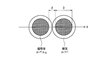
図7は、電波吸収層における磁性酸化鉄粉の体積含率の変化に対する、透磁率実部μ'(符号61)と透磁率虚部μ''(符号62)、さらに、透磁率実部μ'と透磁率虚部μ''とのなす角度であるtanδ(符号63)の値の変化を示す図である。図7は、電波吸収材料としてイプシロン酸化鉄を用いた場合についてのシミュレーション結果を示している。
図8に、図7で結果を示したシミュレーションを行ったモデルを示す。
シミュレーションでは、粒状の磁性体とバインダー樹脂とについて、図7に示すように透磁率μrがμrBである直径Dの磁性体粉を、厚さδ/2の樹脂層(透磁率μr=1)が取り囲んでいるとして計算した。
このとき、電波吸収層全体の透磁率μrは、下記式(3)のように表すことができる。

ここで、図8に示したモデルから、電波吸収層に示す磁性体粉の体積含率は、直径Dとδとの関係から、上記式(4)として表すことができる。
式(3)と式(4)とから、式(5)を導くことができるので、式(5)を用いて、それぞれ透磁率実部μ'と透磁率虚部μ''とを求め、図示したものが図6である。
図7に示すように、イプシロン酸化鉄の体積含率φが大きくなるほど、透磁率虚部μ''(符号62)の値が大きくなり、tanδ(符号63)の値も大きくなっていく。このことから、電波吸収層に占めるイプシロン酸化鉄の体積含率φが大きいほど、より効率よく電波を吸収することが確認できる。一方で、電波吸収層におけるイプシロン酸化鉄の体積含率が大きくなることは、電波吸収層におけるバインダーの割合が減少することであり、一定以上の体積含率の場合には電波吸収層が脆くなってシートとしての形状を維持できない状態となってしまう。
発明者らの検討の結果、電波吸収度合いとして減衰率-15dB以上、電波吸収割合として90%以上を実現するためには、イプシロン酸化鉄の体積含率としては30%以上が好ましいことが分かった。また、イプシロン酸化鉄の体積含率が、40%以上であれば電波吸収性能の観点から好ましく、さらに、イプシロン酸化鉄の体積含率が、50%以上であればより好ましいことがわかった。
本実施形態の電波吸収層は、上記説明したように磁性塗料を作製してこれを塗布、乾燥した後に、カレンダ処理を行って形成する。この場合、磁性塗料の作製時の磁性酸化物の組成上の体積含率を63.8%としたとき、塗布、乾燥した状態のカレンダ処理前での空隙率が27.5%程度であり、電波吸収層としての空隙部分を含んだ実際の磁性酸化鉄の体積含率は46.3%となった。この状態で上述した製造条件でのカレンダ処理を行うことで、空隙率が18.6%となり、空隙を含んだ実際の磁性酸化鉄の体積含率が51.9%となった。 このように、空隙を考慮した磁性酸化鉄の体積含率が50%を超える状態であれば、磁気共鳴による極めて高い電波吸収度合いの電波吸収層を形成することができる。
なお、電波吸収シートとして実用可能であるレベルとしては、電波吸収率-10dB以上であることが好ましいと考えられ、磁性酸化物の体積含率が30%以上であれば、確実に、実用的な電波吸収率を備えた電波吸収シートを実現することができる。また、一般的な材料のバインダーを用いた場合には、磁性酸化鉄の体積含率が80%を超えてしまうと、電波吸収シートとしての可撓性が確保できない状態なってしまう。
これらのことから、電波吸収層における磁性酸化物の体積含率としては、30%以上が好ましく上限は80%程度であるということができる。また、電波吸収層における磁性酸化物の体積含率は、50%以上であることがより好ましいと言うことができる。
なお、電波吸収層を形成するに当たっては、上記のような溶剤を用いた方法に限られず、溶剤を用いずに電波吸収材料をバインダー中に分散配合して形成する方法が考えられる。この場合は、溶媒を用いて作製された電波吸収層として比較して電波吸収層の空隙が少なくなるため、電波吸収層に含まれる電波吸収材料の体積含率が小さくても良好な電波吸収特性が担保されると考えられる。
以上説明したように、本実施形態にかかる電波吸収シートでは、電波吸収材料としてミリ波帯域以上の高い周波数帯域で磁気共鳴を行うイプシロン酸化鉄を用いることで、ミリ波帯域から1テラヘルツまでの周波数帯域の電波を吸収する、電波吸収シートを実現することができる。
なお、上記実施形態では、電波吸収層に含まれる電波吸収材料として、イプシロン酸化鉄を用いたものを例示して説明した。上述のように、イプシロン酸化鉄を用いることで、ミリ波帯域である30ギガヘルツから300ギガヘルツの電波を吸収する電波吸収シートを形成することかでき、さらに、Feサイトを置換する金属材料として、ロジウムなどを用いることによって、電波として規定される最高周波数である1テラヘルツの電波を吸収する電波吸収シートを実現することができる。
しかし、本願で開示する電波吸収シートにおいて、電波吸収層の電波吸収材料として用いられる磁性酸化鉄は、イプシロン酸化鉄には限られない。
フェライト系電磁吸収体としての六方晶フェライトは、76ギガヘルツ帯で電波吸収特性を発揮し、さらにストロンチウムフェライトも数十ギガヘルツ帯域に電波吸収特性を発揮する。このため、イプシロン酸化鉄以外にもこのようなミリ波帯域である30ギガヘルツから300ギガヘルツにおいて電波吸収特性を有する磁性酸化鉄の粒子と、樹脂製バインダーとを用いて電波吸収層を形成することで、ミリ波帯域の電波を吸収する電波吸収シートを実現することができる。
なお、例えば、六方晶フェライトの粒子は、上記実施形態で例示したイプシロン酸化鉄の粒子と比較して平均粒子径が十数μm程度と大きく、また、粒子形状も略球状ではなく板状や針状の結晶となる。このため、樹脂製バインダーを用いて磁性塗料を形成する際に、分散剤の使用や、バインダーとの混練条件を調整して、磁性塗料として塗布した状態において、電波吸収層中になるべく均一に磁性酸化鉄粉が分散された状態で、なおかつ、空隙率がなるべく小さくなるように調整することが好ましい。
また上記の説明において、電波吸収層を形成する方法として、磁性塗料を作製してこれを塗布、乾燥する方法について説明した。本願で開示する電波吸収シートの作製方法としては、上記磁性塗料を塗布する方法の他に、例えば押し出し成型法を用いることが考えられる。
より具体的には、磁性酸化鉄粉と、バインダーと、必要に応じて分散剤などを予めブレンドし、ブレンドされたこれら材料を押出成型機の樹脂供給口から可塑性シリンダ内に供給する。なお、押出成型機としては、可塑性シリンダと、可塑性シリンダの先端に設けられたダイと、可塑性シリンダ内に回転自在に配設されたスクリューと、スクリューを駆動させる駆動機構とを備えた通常の押出成型機を用いることができる。押出成型機のバンドヒータによって可塑化された溶融材料が、スクリューの回転によって前方に送られて先端からシート状に押し出される。押し出された材料を、乾燥、加圧成形、カレンダ処理等を行うことで所定の厚さの電波吸収層を得ることができる。
また、上記実施形態では、電波吸収層が一層で構成された電波吸収シートについて説明したが、電波吸収層として複数の層が積層したものを採用することができる。上述のように本実施形態にかかる電波吸収シートでは、電波吸収層の厚みを調整してそのインピーダンスを空気中のインピーダンスと整合させることで電波吸収特性をより向上させることができる。一方で、電波吸収層を形成する電波吸収材料やバインダーの特性によって、一層では所定の厚さの電波吸収層を形成できない場合には、電波吸収層を積層体として形成することが有効である。
本願で開示する電波吸収シートは、ミリ波帯域以上の高い周波数帯域の電波を吸収する電波吸収シートとして有用である。
1 電波吸収層
1a イプシロン酸化鉄(電波吸収材料)
1b バインダー
2 反射層
3 ベースフィルム(基材)
4 接着層
1a イプシロン酸化鉄(電波吸収材料)
1b バインダー
2 反射層
3 ベースフィルム(基材)
4 接着層
Claims (10)
- 粒子状の電波吸収材料と樹脂製バインダーとを含む可撓性を有する電波吸収層を備えた電波吸収シートであって、
前記電波吸収材料がミリ波帯域以上の周波帯域で磁気共鳴する磁性酸化鉄であることを特徴とする、電波吸収シート。 - 前記電波吸収層に前記電波吸収材料を分散させる分散剤をさらに含む、請求項1に記載の電波吸収シート。
- 前記分散剤がリン酸化合物である、請求項2に記載の電波吸収シート。
- 前記電波吸収材料がイプシロン酸化鉄である、請求項1~3のいずれかに記載の電波吸収シート。
- 前記イプシロン酸化鉄のFeサイトの一部が3価の金属原子で置換されている、請求項4に記載の電波吸収シート。
- 前記電波吸収層における前記磁性酸化鉄の体積含率が30%以上である、請求項1~5のいずれかに記載の電波吸収シート。
- 前記樹脂製バインダーがスルホン酸基およびカルボキシル基の少なくともいずれか一方を含み、かつ、ハロゲンフリーである、請求項1~6のいずれかに記載の電波吸収シート。
- 前記電波吸収層の厚みが1mm以下である、請求項1~7のいずれかに記載の電波吸収シート。
- 前記電波吸収層の一方の面に接して、金属板、金属箔、または、金属蒸着膜からなる反射層が形成されている、請求項1~8のいずれかに記載の電波吸収シート。
- 樹脂製の基材上に、
前記反射層と前記電波吸収層が順次積層されるとともに、
前記基材の前記電波吸収層が配置されている側とは反対側の面に接着層が形成されている、請求項1~9のいずれかに記載の電波吸収シート。
Priority Applications (3)
| Application Number | Priority Date | Filing Date | Title |
|---|---|---|---|
| US16/312,831 US20190215994A1 (en) | 2016-06-22 | 2017-06-21 | Electric wave absorption sheet |
| EP17815460.5A EP3478046A4 (en) | 2016-06-22 | 2017-06-21 | ELECTRIC WAVE ABSORPTION SHEET |
| JP2018502027A JP6764465B2 (ja) | 2016-06-22 | 2017-06-21 | 電波吸収シート |
Applications Claiming Priority (2)
| Application Number | Priority Date | Filing Date | Title |
|---|---|---|---|
| JP2016123493 | 2016-06-22 | ||
| JP2016-123493 | 2016-06-22 |
Publications (1)
| Publication Number | Publication Date |
|---|---|
| WO2017221992A1 true WO2017221992A1 (ja) | 2017-12-28 |
Family
ID=60783451
Family Applications (1)
| Application Number | Title | Priority Date | Filing Date |
|---|---|---|---|
| PCT/JP2017/022912 WO2017221992A1 (ja) | 2016-06-22 | 2017-06-21 | 電波吸収シート |
Country Status (4)
| Country | Link |
|---|---|
| US (1) | US20190215994A1 (ja) |
| EP (1) | EP3478046A4 (ja) |
| JP (2) | JP6764465B2 (ja) |
| WO (1) | WO2017221992A1 (ja) |
Cited By (6)
| Publication number | Priority date | Publication date | Assignee | Title |
|---|---|---|---|---|
| WO2019176612A1 (ja) * | 2018-03-12 | 2019-09-19 | マクセルホールディングス株式会社 | 電磁波吸収体用組成物、電磁波吸収体三次元造形物、それを用いた電子部品及び電子機器、並びにその電子部品及び電子機器の製造方法 |
| WO2019188351A1 (ja) * | 2018-03-28 | 2019-10-03 | マクセルホールディングス株式会社 | 電磁波吸収体 |
| WO2021029249A1 (ja) * | 2019-08-09 | 2021-02-18 | 富士フイルム株式会社 | 電波吸収性組成物および電波吸収体 |
| EP3754673A4 (en) * | 2018-02-15 | 2021-12-08 | The University of Tokyo | MAGNETIC MATERIAL, ASSOCIATED PRODUCTION PROCESS AND ELECTROMAGNETIC WAVES ABSORPTION SHEET |
| JP2022058813A (ja) * | 2018-03-12 | 2022-04-12 | マクセル株式会社 | 実時間送受信装置 |
| WO2022168885A1 (ja) | 2021-02-04 | 2022-08-11 | マクセル株式会社 | 電波吸収体、および電波吸収装置 |
Families Citing this family (8)
| Publication number | Priority date | Publication date | Assignee | Title |
|---|---|---|---|---|
| EP3537861B1 (en) * | 2016-11-04 | 2022-03-30 | Maxell, Ltd. | Electromagnetic-wave-absorbing sheet |
| WO2019077808A1 (ja) * | 2017-10-19 | 2019-04-25 | 関西ペイント株式会社 | ミリ波帯域用電波吸収シート及びミリ波電波吸収方法 |
| JP6461416B1 (ja) * | 2018-06-21 | 2019-01-30 | 加川 清二 | 電磁波吸収複合シート |
| JP6404522B1 (ja) * | 2018-07-03 | 2018-10-10 | 加川 清二 | 電磁波吸収複合シート |
| EP3972401A4 (en) * | 2019-05-14 | 2022-06-29 | FUJIFILM Corporation | Radio wave absorber |
| WO2020244994A1 (en) * | 2019-06-05 | 2020-12-10 | Basf Se | Electromagnetic wave transmission reducing material |
| CN113321963A (zh) * | 2021-06-04 | 2021-08-31 | 宋京忠 | 一种飞机防雷达隐身材料及其制备方法 |
| CN113571919B (zh) * | 2021-07-07 | 2023-06-16 | 佛山(华南)新材料研究院 | 一种吸波器件及其制备方法 |
Citations (10)
| Publication number | Priority date | Publication date | Assignee | Title |
|---|---|---|---|---|
| JP2006080352A (ja) | 2004-09-10 | 2006-03-23 | Hitachi Chem Co Ltd | 電波吸収シート |
| JP2006332260A (ja) * | 2005-05-25 | 2006-12-07 | Hajime Murazaki | 電磁波遮蔽材及び電磁波遮蔽構造体 |
| JP2007193323A (ja) * | 2005-12-22 | 2007-08-02 | Fujifilm Corp | 反射防止フィルム、及びそれを用いたプラズマディスプレイパネル用前面板、プラズマディスプレイパネル表示装置、画像表示装置 |
| JP2008060484A (ja) | 2006-09-01 | 2008-03-13 | Univ Of Tokyo | 電波吸収性磁性結晶および電波吸収体 |
| JP2009059752A (ja) * | 2007-08-30 | 2009-03-19 | Hitachi Chem Co Ltd | 難燃化ノイズ抑制シート |
| JP2011181679A (ja) * | 2010-03-01 | 2011-09-15 | Tdk Corp | 電磁波吸収シート及びその製造方法 |
| JP2011233834A (ja) | 2010-04-30 | 2011-11-17 | Shachihata Inc | 電波吸収体 |
| JP2012071596A (ja) * | 2010-09-02 | 2012-04-12 | Nippon Steel Corp | 導電性、耐食性に優れる塗装金属板 |
| JP2015198163A (ja) | 2014-04-01 | 2015-11-09 | 株式会社リケン | 近傍界用電波吸収シート |
| JP2016111341A (ja) * | 2014-12-03 | 2016-06-20 | 国立大学法人 東京大学 | 電磁波吸収体及び膜形成用ペースト |
Family Cites Families (11)
| Publication number | Priority date | Publication date | Assignee | Title |
|---|---|---|---|---|
| JP4790892B2 (ja) * | 2000-04-27 | 2011-10-12 | ポリマテック株式会社 | 電波吸収体 |
| JP2006032929A (ja) * | 2004-06-14 | 2006-02-02 | Nitta Ind Corp | 電磁干渉抑制体、これを用いる電磁障害抑制方法、およびrf‐idデバイス |
| JP2006156561A (ja) * | 2004-11-26 | 2006-06-15 | Komatsu Seiren Co Ltd | 電磁波シールド材及びその製造方法 |
| JP2006310575A (ja) * | 2005-04-28 | 2006-11-09 | Konica Minolta Photo Imaging Inc | 電磁波吸収転写箔及び電磁波吸収転写箔の付与方法 |
| JP4859791B2 (ja) * | 2006-09-01 | 2012-01-25 | 国立大学法人 東京大学 | 電波吸収材料用の磁性結晶および電波吸収体 |
| EP2447965B1 (en) * | 2009-06-24 | 2020-01-15 | The University of Tokyo | Process for production of magnetic thin film |
| JP6089625B2 (ja) * | 2011-11-30 | 2017-03-08 | 東レ株式会社 | 電波吸収体用シート材およびこれを用いた電波吸収体 |
| US9411076B2 (en) * | 2012-09-14 | 2016-08-09 | Ppg Industries Ohio, Inc. | Pigmented polymerizable compositions and optical articles prepared therefrom |
| JP2014192327A (ja) * | 2013-03-27 | 2014-10-06 | Riken Corp | 近傍界用電波吸収シートおよびその製造方法 |
| JP2015220259A (ja) * | 2014-05-14 | 2015-12-07 | Tdk株式会社 | 磁気抑制シート及びその製造方法 |
| EP3029771B1 (en) * | 2014-12-03 | 2019-10-16 | The University of Tokyo | Electromagnetic wave absorber and film forming paste |
-
2017
- 2017-06-21 US US16/312,831 patent/US20190215994A1/en not_active Abandoned
- 2017-06-21 EP EP17815460.5A patent/EP3478046A4/en not_active Withdrawn
- 2017-06-21 WO PCT/JP2017/022912 patent/WO2017221992A1/ja unknown
- 2017-06-21 JP JP2018502027A patent/JP6764465B2/ja active Active
-
2019
- 2019-07-01 JP JP2019122904A patent/JP2019195083A/ja active Pending
Patent Citations (10)
| Publication number | Priority date | Publication date | Assignee | Title |
|---|---|---|---|---|
| JP2006080352A (ja) | 2004-09-10 | 2006-03-23 | Hitachi Chem Co Ltd | 電波吸収シート |
| JP2006332260A (ja) * | 2005-05-25 | 2006-12-07 | Hajime Murazaki | 電磁波遮蔽材及び電磁波遮蔽構造体 |
| JP2007193323A (ja) * | 2005-12-22 | 2007-08-02 | Fujifilm Corp | 反射防止フィルム、及びそれを用いたプラズマディスプレイパネル用前面板、プラズマディスプレイパネル表示装置、画像表示装置 |
| JP2008060484A (ja) | 2006-09-01 | 2008-03-13 | Univ Of Tokyo | 電波吸収性磁性結晶および電波吸収体 |
| JP2009059752A (ja) * | 2007-08-30 | 2009-03-19 | Hitachi Chem Co Ltd | 難燃化ノイズ抑制シート |
| JP2011181679A (ja) * | 2010-03-01 | 2011-09-15 | Tdk Corp | 電磁波吸収シート及びその製造方法 |
| JP2011233834A (ja) | 2010-04-30 | 2011-11-17 | Shachihata Inc | 電波吸収体 |
| JP2012071596A (ja) * | 2010-09-02 | 2012-04-12 | Nippon Steel Corp | 導電性、耐食性に優れる塗装金属板 |
| JP2015198163A (ja) | 2014-04-01 | 2015-11-09 | 株式会社リケン | 近傍界用電波吸収シート |
| JP2016111341A (ja) * | 2014-12-03 | 2016-06-20 | 国立大学法人 東京大学 | 電磁波吸収体及び膜形成用ペースト |
Non-Patent Citations (1)
| Title |
|---|
| See also references of EP3478046A4 |
Cited By (10)
| Publication number | Priority date | Publication date | Assignee | Title |
|---|---|---|---|---|
| EP3754673A4 (en) * | 2018-02-15 | 2021-12-08 | The University of Tokyo | MAGNETIC MATERIAL, ASSOCIATED PRODUCTION PROCESS AND ELECTROMAGNETIC WAVES ABSORPTION SHEET |
| WO2019176612A1 (ja) * | 2018-03-12 | 2019-09-19 | マクセルホールディングス株式会社 | 電磁波吸収体用組成物、電磁波吸収体三次元造形物、それを用いた電子部品及び電子機器、並びにその電子部品及び電子機器の製造方法 |
| JPWO2019176612A1 (ja) * | 2018-03-12 | 2021-03-25 | マクセルホールディングス株式会社 | 電磁波吸収体用組成物、電磁波吸収体三次元造形物、それを用いた電子部品及び電子機器、並びにその電子部品及び電子機器の製造方法 |
| JP2022058813A (ja) * | 2018-03-12 | 2022-04-12 | マクセル株式会社 | 実時間送受信装置 |
| JP7141444B2 (ja) | 2018-03-12 | 2022-09-22 | マクセル株式会社 | 電磁波吸収体用組成物、電磁波吸収体三次元造形物、それを用いた電子部品及び電子機器、並びにその電子部品及び電子機器の製造方法 |
| JP7308312B2 (ja) | 2018-03-12 | 2023-07-13 | マクセル株式会社 | 実時間送受信装置 |
| WO2019188351A1 (ja) * | 2018-03-28 | 2019-10-03 | マクセルホールディングス株式会社 | 電磁波吸収体 |
| WO2021029249A1 (ja) * | 2019-08-09 | 2021-02-18 | 富士フイルム株式会社 | 電波吸収性組成物および電波吸収体 |
| JPWO2021029249A1 (ja) * | 2019-08-09 | 2021-02-18 | ||
| WO2022168885A1 (ja) | 2021-02-04 | 2022-08-11 | マクセル株式会社 | 電波吸収体、および電波吸収装置 |
Also Published As
| Publication number | Publication date |
|---|---|
| EP3478046A1 (en) | 2019-05-01 |
| EP3478046A4 (en) | 2020-02-19 |
| JP2019195083A (ja) | 2019-11-07 |
| US20190215994A1 (en) | 2019-07-11 |
| JPWO2017221992A1 (ja) | 2018-09-27 |
| JP6764465B2 (ja) | 2020-09-30 |
Similar Documents
| Publication | Publication Date | Title |
|---|---|---|
| WO2017221992A1 (ja) | 電波吸収シート | |
| JP7030694B2 (ja) | 電磁波吸収体 | |
| JP6445741B2 (ja) | 電磁波吸収シート | |
| JP6454445B2 (ja) | 電磁波吸収シート | |
| JPWO2018235952A1 (ja) | 電磁波吸収性組成物、電磁波吸収シート | |
| JP2023067902A (ja) | 電磁波吸収体用組成物、および、電磁波吸収体 | |
| JP2018056492A (ja) | 電波吸収シート | |
| TWI787517B (zh) | 電磁波吸收體及電磁波吸收體用組成物 | |
| CN112237057B (zh) | 电磁波吸收体 | |
| WO2022168885A1 (ja) | 電波吸収体、および電波吸収装置 |
Legal Events
| Date | Code | Title | Description |
|---|---|---|---|
| ENP | Entry into the national phase |
Ref document number: 2018502027 Country of ref document: JP Kind code of ref document: A |
|
| 121 | Ep: the epo has been informed by wipo that ep was designated in this application |
Ref document number: 17815460 Country of ref document: EP Kind code of ref document: A1 |
|
| NENP | Non-entry into the national phase |
Ref country code: DE |
|
| ENP | Entry into the national phase |
Ref document number: 2017815460 Country of ref document: EP Effective date: 20190122 |