EP4073443B1 - Vakuumschubladeneinrichtung zur lagerung von lebensmitteln - Google Patents
Vakuumschubladeneinrichtung zur lagerung von lebensmitteln Download PDFInfo
- Publication number
- EP4073443B1 EP4073443B1 EP20820907.2A EP20820907A EP4073443B1 EP 4073443 B1 EP4073443 B1 EP 4073443B1 EP 20820907 A EP20820907 A EP 20820907A EP 4073443 B1 EP4073443 B1 EP 4073443B1
- Authority
- EP
- European Patent Office
- Prior art keywords
- drawer
- interior
- vacuum
- lid
- cover
- Prior art date
- Legal status (The legal status is an assumption and is not a legal conclusion. Google has not performed a legal analysis and makes no representation as to the accuracy of the status listed.)
- Active
Links
Images


Classifications
-
- A—HUMAN NECESSITIES
- A47—FURNITURE; DOMESTIC ARTICLES OR APPLIANCES; COFFEE MILLS; SPICE MILLS; SUCTION CLEANERS IN GENERAL
- A47B—TABLES; DESKS; OFFICE FURNITURE; CABINETS; DRAWERS; GENERAL DETAILS OF FURNITURE
- A47B88/00—Drawers for tables, cabinets or like furniture; Guides for drawers
- A47B88/90—Constructional details of drawers
- A47B88/919—Accessories or additional elements for drawers, e.g. drawer lighting
-
- A—HUMAN NECESSITIES
- A47—FURNITURE; DOMESTIC ARTICLES OR APPLIANCES; COFFEE MILLS; SPICE MILLS; SUCTION CLEANERS IN GENERAL
- A47B—TABLES; DESKS; OFFICE FURNITURE; CABINETS; DRAWERS; GENERAL DETAILS OF FURNITURE
- A47B77/00—Kitchen cabinets
- A47B77/04—Provision for particular uses of compartments or other parts ; Compartments moving up and down, revolving parts
- A47B77/16—Provision for particular uses of compartments or other parts ; Compartments moving up and down, revolving parts by adaptation of compartments or drawers for receiving or holding foodstuffs; by provision of rotatable or extensible containers for foodstuffs
-
- A—HUMAN NECESSITIES
- A47—FURNITURE; DOMESTIC ARTICLES OR APPLIANCES; COFFEE MILLS; SPICE MILLS; SUCTION CLEANERS IN GENERAL
- A47B—TABLES; DESKS; OFFICE FURNITURE; CABINETS; DRAWERS; GENERAL DETAILS OF FURNITURE
- A47B88/00—Drawers for tables, cabinets or like furniture; Guides for drawers
- A47B88/40—Sliding drawers; Slides or guides therefor
- A47B88/453—Actuated drawers
- A47B88/457—Actuated drawers operated by electrically-powered actuation means
-
- A—HUMAN NECESSITIES
- A47—FURNITURE; DOMESTIC ARTICLES OR APPLIANCES; COFFEE MILLS; SPICE MILLS; SUCTION CLEANERS IN GENERAL
- A47B—TABLES; DESKS; OFFICE FURNITURE; CABINETS; DRAWERS; GENERAL DETAILS OF FURNITURE
- A47B88/00—Drawers for tables, cabinets or like furniture; Guides for drawers
- A47B88/90—Constructional details of drawers
- A47B88/969—Drawers having means for organising or sorting the content
-
- B—PERFORMING OPERATIONS; TRANSPORTING
- B65—CONVEYING; PACKING; STORING; HANDLING THIN OR FILAMENTARY MATERIAL
- B65D—CONTAINERS FOR STORAGE OR TRANSPORT OF ARTICLES OR MATERIALS, e.g. BAGS, BARRELS, BOTTLES, BOXES, CANS, CARTONS, CRATES, DRUMS, JARS, TANKS, HOPPERS, FORWARDING CONTAINERS; ACCESSORIES, CLOSURES, OR FITTINGS THEREFOR; PACKAGING ELEMENTS; PACKAGES
- B65D81/00—Containers, packaging elements, or packages, for contents presenting particular transport or storage problems, or adapted to be used for non-packaging purposes after removal of contents
- B65D81/18—Containers, packaging elements, or packages, for contents presenting particular transport or storage problems, or adapted to be used for non-packaging purposes after removal of contents providing specific environment for contents, e.g. temperature above or below ambient
- B65D81/20—Containers, packaging elements, or packages, for contents presenting particular transport or storage problems, or adapted to be used for non-packaging purposes after removal of contents providing specific environment for contents, e.g. temperature above or below ambient under vacuum or superatmospheric pressure, or in a special atmosphere, e.g. of inert gas
- B65D81/2007—Containers, packaging elements, or packages, for contents presenting particular transport or storage problems, or adapted to be used for non-packaging purposes after removal of contents providing specific environment for contents, e.g. temperature above or below ambient under vacuum or superatmospheric pressure, or in a special atmosphere, e.g. of inert gas under vacuum
- B65D81/2038—Containers, packaging elements, or packages, for contents presenting particular transport or storage problems, or adapted to be used for non-packaging purposes after removal of contents providing specific environment for contents, e.g. temperature above or below ambient under vacuum or superatmospheric pressure, or in a special atmosphere, e.g. of inert gas under vacuum with means for establishing or improving vacuum
-
- A—HUMAN NECESSITIES
- A47—FURNITURE; DOMESTIC ARTICLES OR APPLIANCES; COFFEE MILLS; SPICE MILLS; SUCTION CLEANERS IN GENERAL
- A47B—TABLES; DESKS; OFFICE FURNITURE; CABINETS; DRAWERS; GENERAL DETAILS OF FURNITURE
- A47B88/00—Drawers for tables, cabinets or like furniture; Guides for drawers
- A47B88/90—Constructional details of drawers
- A47B88/969—Drawers having means for organising or sorting the content
- A47B2088/976—Drawers having means for organising or sorting the content with separate holders
-
- A—HUMAN NECESSITIES
- A47—FURNITURE; DOMESTIC ARTICLES OR APPLIANCES; COFFEE MILLS; SPICE MILLS; SUCTION CLEANERS IN GENERAL
- A47B—TABLES; DESKS; OFFICE FURNITURE; CABINETS; DRAWERS; GENERAL DETAILS OF FURNITURE
- A47B2210/00—General construction of drawers, guides and guide devices
- A47B2210/06—Drawer liners
-
- A—HUMAN NECESSITIES
- A47—FURNITURE; DOMESTIC ARTICLES OR APPLIANCES; COFFEE MILLS; SPICE MILLS; SUCTION CLEANERS IN GENERAL
- A47B—TABLES; DESKS; OFFICE FURNITURE; CABINETS; DRAWERS; GENERAL DETAILS OF FURNITURE
- A47B2210/00—General construction of drawers, guides and guide devices
- A47B2210/08—Covers or lids for sliding drawers
-
- A—HUMAN NECESSITIES
- A47—FURNITURE; DOMESTIC ARTICLES OR APPLIANCES; COFFEE MILLS; SPICE MILLS; SUCTION CLEANERS IN GENERAL
- A47B—TABLES; DESKS; OFFICE FURNITURE; CABINETS; DRAWERS; GENERAL DETAILS OF FURNITURE
- A47B2210/00—General construction of drawers, guides and guide devices
- A47B2210/17—Drawers used in connection with household appliances
Definitions
- the present invention describes a vacuum drawer device, comprising a drawer which can be moved linearly in a direction of thrust movement and has at least one drawer interior, which can be closed by means of an airtight lid in a lifting movement in a lifting direction controlled by electric lifting means and running perpendicular to the direction of thrust movement, the lid being at least one in the Has an air duct leading to the inside of the lid, the air duct being operatively connected to electrical evacuation means in such a way that when the lid is in place, air can be pumped out of the at least one drawer interior through the at least one air duct.
- the vacuum drawer device For the first time in the DE202017006169 generally discloses a vacuum drawer device with a drawer and a lid, whereby a negative pressure could be generated in a drawer interior by means of a pump.
- the vacuum drawer device comprises a drawer with walls and a drawer interior R, wherein the drawer can be operatively connected to a lid and is mounted in a linearly movable manner within a drawer body. More details about the drawer Lid, lifting means and evacuation means are in the DE202017006169 but largely left open.
- the drawer interior is designed in such a way that a plurality of containers are arranged in an orderly position within the drawer, with the containers always having the same height and also, for example, a circumferential flange-like edge.
- Such containers are known and are sold under the name Gastronorm containers.
- the interiors of the containers form the entire drawer interior R and all individual container interiors are closed with the lid and evacuated as a whole.
- users often want to be independent of the type of container, the number of containers used and the positioning of the containers, but still achieve evacuation. This was not possible.
- the present invention has as its object to create a vacuum drawer device with a drawer, a lid, lifting means and evacuation means, which can be automatically evacuated and ventilated, with any non-standard shaped containers, also of different sizes and in different numbers, being able to be used, so that the associated container interiors can be evacuated.
- the vacuum drawer device 0 comprises a drawer 3, which is shown in dashed lines, and a lid 2.
- the drawer 3 can be operatively connected to the lid 2 and is mounted in a linearly movable manner within a drawer body 9.
- the drawer body 9 forms the outer shell in which the lid 2 and the drawer 3 are movably mounted and protected.
- the drawer 3 includes walls and a drawer interior R and is mounted so that it can move open and closed in a linear pushing movement direction S and is designed to be evacuable.
- the drawer 3 is mounted in a linearly movable manner in a drawer pull-out 31 ', so that the drawer 3 can be brought into an open position and a closed position.
- the evacuable drawer interior R is formed by a plurality of containers 14, the containers 14 being arranged positioned within the drawer 3 and each having the same height, but different sizes.
- the containers 14 are preferably designed as gastronorm containers, the interiors of which can form the entire drawer interior R, which can be closed and evacuated by means of a lid 2.
- the containers 14 are stored in the drawer 3 and can be moved with the drawer 3, but can also be removed.
- the key point for evacuating the drawer interior R is the lid 2, which is movably arranged within the drawer body 9 and is designed to be airtight and can be lowered onto the drawer 3 in a lifting direction H perpendicular to the pushing movement direction S.
- Lifting means 7 are arranged on or in the lid 2 and within the drawer body 9, which hold the lid 2 movable within the drawer body 9 in the lifting direction H. With a lid side facing the drawer 3, the lid 2 can be placed on the edges of the container 14, whereby the at least one Drawer interior R can be locked.
- the lid 2 is mounted movably relative to the drawer body 9 and the drawer 3. Closing only takes place when the drawer 3 is in the closed position, and when the drawer 3 is in the open position according to Figure 1 the lid 2 releases the drawer 3 completely.
- servo motors 7 are attached to the lid 2, operatively connected to lifting means within the drawer body 9.
- Rotatable servo disks 71 ' are each held within the body 9 via a screw with a bearing sleeve 72' in such a way that the lid 2 can be raised in an oppositely controlled manner by the drawer 3 or the containers 14 and can be lowered onto them.
- the containers 14 within the drawer 3 of the vacuum drawer device 0 can be locked at the top compared to conventional drawers by the user manually closing the drawer 3 and closing the drawer Lid 2 is lowered onto the container 14 in the closed position of the drawer 3 and seals it airtight from above.
- a closed position sensor 6, a control switch/on and off switch 15 and a proximity sensor 18 are attached to the front of the lid 2.
- the containers 14 are located within the drawer body 9 during the closed position of the drawer 3, the lid 2 resting on the containers 14 in this situation and thereby sealing the container interior R from above in an airtight manner.
- the cover 2 is profiled in such a way that evacuation means in the form of a pump 1, a pressure sensor 16 and a valve 4 are integrated into at least one recess A in the cover 2.
- a control 8 for automating the evacuation means and lifting means is also integrated into the lid 2, but this can also be attached to the drawer body 9 outside the lid 2.
- the profiled lid 2 forms one Frame 17 for the evacuation means.
- the cover 2 here includes, for example, the profiling or the frame 17 and a foam layer 22 '.
- the lid 2 can also be made in one piece from one material.
- On the lower side, facing the containers 14, an airtight membrane 21 ' is arranged.
- the container interior R can be sealed airtight by means of the airtight membrane 21 ', which is placed on the opening of the drawer 3 or on the openings of the container 14 by means of a lid 2.
- the airtight membrane 21' has an air inlet opening 23' for each container interior R. This air inlet opening 23' leads either directly to an air duct 11' or indirectly through the foam layer 22' to an air duct 11'.
- the air duct 11 ' crosses the cover 2 at least partially and leads out of the cover 2.
- the air duct 11' is connected to at least one air inlet opening 23', so that air can be guided out of the lid 2 from the air inlet opening 23' through the air duct 11'.
- the air duct 11' is connected to the inside of the lid or recesses A, in which the evacuation means are arranged.
- the controller 8 When the lid 2 has been placed on the drawer 3 or on the containers 14, air is pumped out of the at least one drawer interior R through the air duct 11 'controlled by the controller 8.
- the cover 2 is designed to be very compact by integrating the components and only control cables 11 lead through the cover 2 or the foam layer 22 'and a cable from the cover 2 into a power supply unit.
- a handle 12 On a front panel 13, which closes the drawer 3 in the opening direction, there is a handle 12 on the outside and on the front of the lid 2, aligned with the handle 12, the proximity sensor 18 and the closed position sensor 6.
- the required electricity is supplied to the lid 2 or the devices in the drawer body 9 to control the vacuum in the container interior R by connecting the lid 2 using a power cable 10, which in turn is connected to the power supply.
- the controller 8 can use a proximity sensor 18 to detect whether the drawer 3 is open or closed.
- the proximity sensor 18 is connected to the controller 8 via the control cable 11.
- the controller 8 further monitors the internal pressure in at least one container interior R of the drawer 3 by means of a pressure sensor 16.
- the controller 8 takes over the regulation of the vacuum pump 1 and the solenoid valve 4. The Air that was withdrawn from the drawer 3 is released into the environment, which is indicated by a dashed arrow in Figure 2 is marked.
- the vacuum drawer device 0 comprising a drawer 3 which can be moved linearly in a thrust movement direction S and has at least one drawer interior R, which runs perpendicular to the thrust movement direction S by means of an airtight lid 2 in a lifting movement in a lifting direction H controlled by electrical lifting means 7 can be closed, the lid 2 having at least one air duct 11 'leading into the interior of the lid, the air duct 11' being operatively connected to electrical evacuation means in such a way that when the lid 2 rests on the drawer 3, air is automatically released from the at least one drawer interior R through the at least one air duct 11 'can be pumped out.
- the lid 2 or the lifting means 7 are attached to the drawer body 9 using a mounting bracket 19.
- Most of the components were from the vacuum drawer device 0 according to Figures 1 and 2 adopted, but drawer 3 has been further developed so that it is independent of the type the container 14, food can be stored evacuated in the drawer interior R.
- the lid 2 and support means on the drawer 3 are designed in such a way that the lid 2 can be placed indirectly on the drawer 3.
- a sealing fitting D is arranged along the drawer inner walls 30 on the lid side of the drawer 3.
- the sealing fitting D or the majority of the sealing fittings D, which are designed to be airtight and preferably comprise metal angles, are arranged, glued or screwed, around the entire inner circumference of the drawer 3. Accordingly, this at least one sealing fitting D can be described as peripheral.
- sealing fittings D which are arranged at the same height as the drawer edge X
- sealing fittings D crossing the circumference of the drawer can also be arranged. These sealing fittings D are clamped between two opposite drawer walls 30 on the side of the drawer 3 facing the lid 2. A sealing fitting D can also be clamped between directly adjacent drawer walls 30.
- the empty drawer interior R can be filled with food in different containers, whereby the container sizes should be smaller than the distance between the sealing fittings D. Since the lid 2 rests sealingly on the sealing fittings D, the containers 14 do not have to have any flanges and also no minimum sizes.
- the sealing fittings D are flush with the drawer edge X on the drawer walls 30 of the drawer 3 and are arranged between at least two adjacent drawer edges X.
- the front panel 13 is designed as an extended drawer wall 30, but the sealing fitting D is arranged at the level of the surrounding drawer edges X, which is problem-free if the lid 2 does not protrude over the front panel 13.
- sealing means 24 ' are arranged, which are operatively connected to the sealing fittings D when the lid 2 is in the closed position, i.e. is moved in the lifting direction H towards the drawer interior R.
- Single-layer or multi-layer plastic layers can be used as sealing means 24 ', through which an airtight seal can be achieved.
- sealing fittings D can also be arranged on the drawer walls 30, which extend out of the drawer interior R at a distance from the drawer edge X.
- the airtight sealing fittings D should be designed as an angle, one leg of which leads vertically out of the drawer 3 and the other leg of which serves as a support for the lid 2 or the sealing means 24 '.
- sealing fittings D crossing one another can be used, as in Figure 5a shown, can be arranged stretched between two opposite drawer walls 30 of the drawer 3.
- an intersection is created, so that a total of four storage sections for containers within the drawer 3 are delimited.
- airtight partitions can be arranged below the intersecting sealing fittings D between the sealing fitting D and the bottom of the drawer 3, leading through the drawer interior R. No intermediate walls need to be arranged along the edge sealing fittings D.
- the edge sealing fittings D and also the crossing sealing fittings D can be designed as airtight angles or U-profiles made of metal or plastic.
- the sealing fittings D must be sufficiently stable so that they can withstand the counter pressure of the lid 2 on the opening of the drawer interior R.
- the lid 2 should be constructed in a sandwich construction. This guarantees the required rigidity of the cover 2.
- the rigidity is needed for sealing.
- the cover layers are therefore connected to the core layer in a force-fitting manner. This design ensures high rigidity with a low overall height and low mass. Cover layers can be made from glass and core layers can be made from stiff, airtight foam.
Landscapes
- Engineering & Computer Science (AREA)
- Mechanical Engineering (AREA)
- Pressure Vessels And Lids Thereof (AREA)
- Drawers Of Furniture (AREA)
- Packages (AREA)
- Vacuum Packaging (AREA)
- Closures For Containers (AREA)
Description
- Die vorliegende Erfindung beschreibt eine Vakuumschubladeneinrichtung, umfassend eine in eine Schubbewegungsrichtung linear bewegbare Schublade mit mindestens einem Schubladeninnenraum, welcher mittels eines luftdicht ausgestalteten Deckels in einer Hubbewegung in einer Hubrichtung durch elektrische Hubmittel gesteuert senkrecht zur Schubbewegungsrichtung verlaufend verschliessbar ist, wobei der Deckel mindestens einen in das Deckelinnere führenden Luftkanal aufweist, wobei der Luftkanal derart mit elektrischen Evakuiermitteln wirkverbunden ist, dass bei Auflage des Deckels Luft aus dem mindestens einen Schubladeninnenraum durch den mindestens einen Luftkanal abpumpbar ist.
- Seit kurzem wird die Lagerung von Lebensmitteln vor allem in Privathaushalten durch Vakuumschubladeneinrichtungen unterstützt, was in Zukunft einige Kühlschränke überflüssig machen wird.
- Erstmals wurde in der
DE202017006169 allgemein eine Vakuumschubladeneinrichtung mit einer Schublade und einem Deckel offenbart, wobei mittels einer Pumpe ein Unterdruck in einem Schubladeninnenraum erzeugt werden konnte. Die Vakuumschubladeneinrichtung umfasst eine Schublade mit Wänden und einen Schubladeninnenraum R, wobei die Schublade mit einem Deckel wirkverbindbar ist und innerhalb eines Schubladenkorpus linear bewegbar gelagert ist. Genauere Details über die Schublade, den Deckel, Hubmittel und Evakuiermittel sind in derDE202017006169 aber weitgehend offengelassen. - In der
WO2019/141574 wird der Schubladeninnenraum so ausgestaltet, dass eine Mehrzahl von Behältern innerhalb der Schublade geordnet positioniert angeordnet sind, wobei die Behälter immer die gleiche Höhe aufweisen und auch beispielsweise einen umlaufenden flanschartigen Rand. Derartige Behälter sind bekannt und werden unter dem Namen Gastronormbehälter vertrieben. Die Innenräume der Behälter bilden den gesamten Schubladeninnenraum R und alle einzelnen Behälterinnenräume werden mit dem Deckel verschlossen und gesamthaft evakuiert. Anwender möchten aber oft unabhängig von der Art der Behälter, der Menge eingesetzter Behälter und auch der Positionierung der Behälter sein, die Evakuierung aber trotzdem erreichen. Dies war so nicht möglich. - Die vorliegende Erfindung hat sich zur Aufgabe gestellt eine Vakuumschubladeneinrichtung mit einer Schublade, einem Deckel, Hubmitteln und Evakuiermitteln zur schaffen, welche automatisiert evakuierbar und belüftbar ist, wobei beliebig geformte, nicht genormte Behälter, auch mit unterschiedlichen Grössen und in unterschiedlicher Anzahl einsetzbar sind, sodass die zugehörigen Behälterinnenräume evakuierbar sind.
- Dies erfüllt eine Vorrichtung mit den Merkmalen des Patentanspruches 1.
- Es soll zudem möglich sein, in einzelnen Behälterinnenräumen unterschiedliche Unterdrücke zu erreichen, wobei nur ein Deckel verwendet wird.
- Variationen von Merkmalskombinationen bzw. geringfügige Anpassungen der Erfindung sind in der Detailbeschreibung zu finden, in den Figuren abgebildet und in die abhängigen Patentansprüche aufgenommen worden.
- Der Erfindungsgegenstand wird nachstehend detailliert im Zusammenhang mit den anliegenden Zeichnungen beschrieben.
- Es sind dargestellt in
- Figur 1
- zeigt eine perspektivische Ansicht einer aus dem Stand der Technik bekannte Vakuumschubladeneinrichtung in einem Schubladenkorpus bei offener Schublade, während
- Figur 2
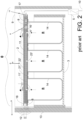
- einen teilweise schematisch dargestellten Längsschnitt durch eine Vakuumschubladeneinrichtung der
Figur 1 in einem Schubladenkorpus bei geschlossener Vakuumschubladeneinrichtung zeigt. - Figur 3
- zeigt eine perspektivische Ansicht einer Vakuumschubladeneinrichtung mit weiterentwickelter Schublade, während
- Figur4
- eine Schnittzeichnung der Vakuumschubladeneinrichtung gemäss
Figur 3 in einer Geschlossenstellung der Schublade zeigt. - Figur 5a
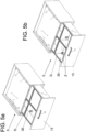
- zeigt eine perspektivische Ansicht einer Vakuumschubladeneinrichtung mit umlaufenden Dichtungsbeschlägen und zwei sich kreuzende Dichtungsbeschläge, während
- Figur 5b
- eine perspektivische Ansicht der Vakuumschubladeneinrichtung gemäss
Figur 5a zeigt, wobei an den Dichtungsbeschlägen zusätzlich Zwischenwände in den Schubladeninnenraum integriert sind. - Wie aus dem Stand der Technik der
WO WO2019/141574 bekannt, wird die Vakuumschubladeneinrichtung insgesamt mit 0 bezeichnet. Dabei umfasst die Vakuumschubladeneinrichtung 0 eine Schublade 3, welche gestrichelt gezeichnet ist und einen Deckel 2. Die Schublade 3 ist mit dem Deckel 2 wirkverbindbar und innerhalb eines Schubladenkorpus 9 linear bewegbar gelagert. Der Schubladenkorpus 9 bildet die äussere Hülle, in welcher der Deckel 2 und die Schublade 3 bewegbar geschützt gelagert sind. Die Schublade 3 umfasst Wände und einen Schubladeninnenraum R und ist in einer linearen Schubbewegungsrichtung S auf und zu bewegbar gelagert und evakuierbar ausgestaltet. Gemäss Stand der Technik ist die Schublade 3 in einem Schubladenauszug 31' linear bewegbar gelagert, sodass die Schublade 3 in eine Offenstellung und eine Schliessstellung bringbar ist. Der evakuierbare Schubladeninnenraum R ist von einer Mehrzahl von Behältern 14 gebildet, wobei die Behälter 14 innerhalb der Schublade 3 positioniert angeordnet sind und jeweils die gleiche Höhe aufweisen, jedoch verschiedene Grössen. Bevorzugt sind die Behälter 14 als Gastronormbehälter ausgebildet, deren Innenräume den gesamten Schubladeninnenraum R bilden können, welcher mittels Deckel 2 verschliessbar und evakuierbar ist. Die Behälter 14 sind in der Schublade 3 gelagert und sind mit der Schublade 3 mitbewegbar, können aber auch entnommen werden. - Der Kernpunkt zur Evakuierung des Schubladeninnenraums R ist der bewegbar innerhalb des Schubladenkorpus 9 angeordnete Deckel 2, welcher luftdicht ausgestaltet ist und in einer Hubrichtung H senkrecht zur Schubbewegungsrichtung S auf die Schublade 3 absenkbar gelagert ist. Am oder im Deckel 2 und innerhalb des Schubladenkorpus 9 sind Hubmittel 7 angeordnet, welche den Deckel 2 innerhalb des Schubladenkorpus 9 in Hubrichtung H bewegbar halten. Mit einer, der Schublade 3 zugewandten Deckelseite kann der Deckel 2 auf Ränder der Behälter 14 aufgesetzt werden, wodurch der mindestens eine Schubladeninnenraum R verschliessbar ist. Der Deckel 2 ist relativ zum Schubladenkorpus 9 und zur Schublade 3 bewegbar gelagert. Das Verschliessen findet nur bei Geschlossenstellung der Schublade 3 statt, bei Offenstellung der Schublade 3 gemäss
Figur 1 gibt der Deckel 2 die Schublade 3 vollständig frei. - Als Hubmittel 7 sind hier mehrere Servomotoren 7 am Deckel 2 wirkverbunden mit Hubmitteln innerhalb des Schubladenkorpus 9 befestigt. Drehbare Servoscheiben 71' sind jeweils über eine Schraube mit Lagerhülse 72' innerhalb des Korpus 9 so gehalten, dass der Deckel 2 von der Schublade 3 bzw. den Behältern 14 entgegengesetzt gesteuert anhebbar und auf diese absenkbar angeordnet ist. Damit entsteht die Hubbewegung des Deckels 2 in Hubrichtung H senkrecht zur Schubbewegungsrichtung S der Schublade 3. Die Behälter 14 innerhalb der Schublade 3 der Vakuumschubladeneinrichtung 0 können gegenüber gebräuchlichen Schubladen gegen oben abgeschlossen werden, indem der Nutzer von Hand, die Schublade 3 schliesst und sich der Deckel 2 in der Geschlossenstellung der Schublade 3 auf die Behälter 14 herabsenkt und diese von oben luftdicht abschliesst. An der Vorderseite des Deckels 2 sind ein Geschlossenstellungssensor 6, ein Bedienschalter/An- und Ausschalter 15 und ein Näherungssensor 18 angebracht.
- Wie in
Figur 2 dargestellt befinden sich die Behälter 14 während der Geschlossenstellung der Schublade 3 innerhalb des Schubladenkorpus 9 wobei der Deckel 2 in dieser Situation auf den Behältern 14 aufliegt und dadurch die Behälterinnenräume R von oben luftdicht abschliesst. - Der Deckel 2 ist derart profiliert, das Evakuiermittel in Form einer Pumpe 1, eines Drucksensors 16 und eines Ventils 4 in mindestens einer Aussparung A im Deckel 2 integriert befestigt sind. Auch eine Steuerung 8, zur Automatisierung der Evakuiermittel und Hubmittel ist hier in den Deckel 2 integriert, diese kann aber auch ausserhalb des Deckels 2 am Schubladenkorpus 9 befestigt sein. Der profilierte Deckel 2 bildet einen Rahmen 17 für die Evakuiermittel. Der Deckel 2 umfasst hier beispielhaft die Profilierung bzw. den Rahmen 17 und eine Schaumstofflage 22'. Der Deckel 2 kann aber auch einstückig aus einem Material hergestellt sein. Auf der unteren Seite, den Behältern 14 zugewandt ist eine luftdichte Membran 21' angeordnet. Durch die luftdichte Membran 21' welche mittels Deckel 2 auf die Öffnung der Schublade 3 bzw. auf die Öffnungen der Behälter 14 aufgesetzt wird, kann der Behälterinnenraum R luftdicht verschlossen werden. Die luftdichte Membran 21' weist zu jedem Behälterinnenraum R eine Lufteinlassöffnung 23' auf. Diese Lufteinlassöffnung 23' führt entweder direkt zu einem Luftkanal 11' oder durch die Schaumstofflage 22' indirekt zu einem Luftkanal 11'. Der Luftkanal 11' quert den Deckel 2 mindestens teilweise und führt aus dem Deckel 2 heraus. Der Luftkanal 11' ist mit mindestens einer Lufteinlassöffnung 23' verbunden, sodass Luft von der Lufteinlassöffnung 23' durch den Luftkanal 11' aus dem Deckel 2 heraus führbar ist.
- Um Luft durch den Luftkanal 11' zu entnehmen ist der Luftkanal 11' mit dem Deckelinneren bzw. Aussparungen A verbunden, in welchen die Evakuiermittel angeordnet sind. Wenn der Deckel 2 auf der Schublade 3 bzw. auf den Behältern 14 aufgesetzt wurde, wird Luft aus dem mindestens einen Schubladeninnenraum R durch den Luftkanal 11' gesteuert durch die Steuerung 8 abgepumpt. Der Deckel 2 ist durch Integration der Bauteile sehr kompakt ausgestaltet und es führen lediglich Steuerkabel 11 durch den Deckel 2 bzw. die Schaumstofflage 22' und ein Kabel vom Deckel 2 weg in ein Netzgerät.
- Auf einer Frontblende 13, welche die Schublade 3 in Öffnungsrichtung abschliesst, befindet sich auf der Aussenseite ein Griff 12 und auf Vorderseite des Deckels 2, zum Griff 12 ausgerichtet, der Näherungssensor 18 und der Geschlossenstellungssensor 6.
- Der benötigte Strom wird dem Deckel 2 bzw. den Geräten im Schubladenkorpus 9 zur Steuerung des Vakuums im Behälterinnenraum R zugeführt, indem der Deckel 2 mittels Stromkabel 10 verbunden ist, welches wiederum mit dem Netzgerät verbunden ist.
- Die Steuerung 8 kann mittels Näherungssensor 18 erkennen, ob die Schublade 3 offen oder geschlossen ist. Der Näherungssensor 18 ist mit der Steuerung 8 über das Steuerkabel 11 verbunden. Weiter überwacht die Steuerung 8 mittels Drucksensor 16 den Innendruck im mindestens einen Behälterinnenraum R der Schublade 3. Zusätzlich übernimmt die Steuerung 8 die Regelung der Vakuumpumpe 1 und des Elektromagnetventils 4. Durch einen mit der Vakuumpumpe 1 verbundenen Luftschlauch bzw. dem Luftkanal 11' wird die Luft, welche der Schublade 3 entzogen wurde, an die Umgebung abgegeben, was mit einem gestrichelten Pfeil in
Figur 2 gekennzeichnet ist. - Die folgende Weiterentwicklung, basiert auf der Vakuumschubladeneinrichtung 0, umfassend eine in eine Schubbewegungsrichtung S linear bewegbare Schublade 3 mit mindestens einem Schubladeninnenraum R, welcher mittels eines luftdicht ausgestalteten Deckels 2 in einer Hubbewegung in einer Hubrichtung H durch elektrische Hubmittel 7 gesteuert senkrecht zur Schubbewegungsrichtung S verlaufend verschliessbar ist, wobei der Deckel 2 mindestens einen in das Deckelinnere führenden Luftkanal 11' aufweist, wobei der Luftkanal 11' derart mit elektrischen Evakuiermitteln wirkverbunden ist, dass bei Auflage des Deckels 2 auf der Schublade 3 Luft automatisiert aus dem mindestens einen Schubladeninnenraum R durch den mindestens einen Luftkanal 11' abpumpbar ist. Der Deckel 2 bzw. die Hubmittel 7 sind hier mittels Montagewinkel 19 am Schubladenkorpus 9 befestigt. Die meisten Bauteile wurde aus der Vakuumschubladeneinrichtung 0 gemäss
Figuren 1 und2 übernommen, die Schublade 3 aber weiterentwickelt, sodass unabhängig von der Art der Behälter 14, Lebensmittel im Schubladeninnenraum R evakuiert lagerbar sind. - Der Deckel 2 und Auflagemittel an der Schublade 3 sind derart gestaltet, dass der Deckel 2 indirekt auf die Schublade 3 auflegbar ist. Dafür ist ein Dichtungsbeschlag D entlang der Schubladeninnenwände 30 an der Schublade 3 deckelseitig angeordnet. Der Dichtungsbeschlag D oder die Mehrzahl der Dichtungsbeschläge D, welche luftdicht ausgestaltet sind und bevorzugt Metallwinkel umfassen, sind den gesamten Innenumfang der Schublade 3 umlaufend angeordnet, festgeklebt oder verschraubt. Entsprechend kann dieser mindestens eine Dichtungsbeschlag D als randläufig bezeichnet werden.
- Wenn der Deckel 2 mittels der Hubmittel 7 in die Geschlossenstellung gebracht ist, liegt der Deckel 2 auf den Dichtungsbeschlägen D auf und es ist eine Evakuierung des darunterliegenden Schubladeninnenraums R erreichbar. Neben den umlaufenden Dichtungsbeschlägen D, die auf der gleichen Höhe, wie der Schubladenrand X angeordnet sind, können auch den Schubladenumfang querende Dichtungsbeschläge D angeordnet sein. Diese Dichtungsbeschläge D sind zwischen zwei gegenüberliegenden Schubladenwänden 30 aufgespannt an der dem Deckel 2 zugewandten Seite der Schublade 3. Dabei kann ein Dichtungsbeschlag D auch zwischen direkt benachbart liegenden Schubladenwänden 30 aufgespannt sein.
- Der leere Schubladeninnenraum R kann mit Lebensmitteln in unterschiedlichen Behältern gefüllt werden, wobei die Behältergrössen kleiner, als der Abstand zwischen den Dichtungsbeschlägen D sein sollte. Da der Deckel 2 auf den Dichtungsbeschlägen D dichtend aufliegt, müssen die Behälter 14 keine Flansche aufweisen und auch keine Mindestgrössen.
- Wie in
Figur 4 erkennbar, sind die Dichtungsbeschläge D bündig mit dem Schubladenrand X an den Schubladenwänden 30 der Schublade 3 umlaufend und zwischen mindestens zwei benachbarten Schubladenrändern X angeordnet sind. Hier ist die Frontblende 13, als verlängerte Schubladenwand 30 ausgestaltet, der Dichtungsbeschlag D aber auf Höhe der umliegenden Schubladenränder X angeordnet, was problemlos ist, wenn der Deckel 2 entsprechend nicht über die Frontblende 13 ragt. - Am Deckel 2, an der dem Schubladeninnenraum R zugewandten Seite sind Dichtmittel 24' angeordnet, welche mit den Dichtungsbeschlägen D wirkverbunden sind, wenn der Deckel 2 in Geschlossenstellung ist, also in Hubrichtung H in Richtung Schubladeninnenraum R verfahren ist. Als Dichtmittel 24' können einlagige oder mehrlagige Kunststofflagen verwendet werden, durch welche eine luftdichte Abdichtung erreichbar ist.
- Es können aber auch Dichtungsbeschläge D an den Schubladenwänden 30 angeordnet sein, welche vom Schubladenrand X beabstandet aus dem Schubladeninnenraum R heraus ragend verlaufen. Um eine luftdichte Abdichtung zu erreichen, sollten die luftdichten Dichtungsbeschläge D dazu als Winkel ausgeführt sein, deren einer Schenkel senkrecht aus der Schublade 3 heraus führt und deren anderer Schenkel als Auflage für den Deckel 2 bzw. die Dichtmittel 24' dient.
- Um die Dichtungswirkung noch zu erhöhen, können mehrere einander kreuzende Dichtungsbeschläge D, wie in
Figur 5a gezeigt, zwischen zwei gegenüberliegenden Schubladenwänden 30 der Schublade 3 aufgespannt angeordnet werden. Neben dem entlang des Innenumfangs umlaufenden Dichtungsbeschlag D entsteht eine Kreuzung, sodass insgesamt vier Lagerabschnitte für Behälter innerhalb der Schublade 3 abgegrenzt erreicht sind. - Um mehrere voneinander luftdicht abschliessbare Lagerabschnitte zu erreichen, können unterhalb der sich kreuzenden Dichtungsbeschläge D luftdichte Zwischenwände zwischen dem Dichtungsbeschlag D und dem Boden der Schublade 3 durch den Schubladeninnenraum R führend, angeordnet werden. Dabei brauchen keine Zwischenwände entlang der randläufigen Dichtungsbeschläge D angeordnet sein.
- Die randläufigen Dichtungsbeschläge D und auch die kreuzenden Dichtungsbeschläge D sind als luftdichte Winkel oder U-Profile aus Metall oder Kunststoff ausbildbar. Dabei müssen die Dichtungsbeschläge D ausreichend stabil ausgebildet sein, damit sie dem Gegendruck des Deckels 2 auf der Öffnung des Schubladeninnenraums R standhalten können.
- Die Konstruktion des Deckels 2 sollte in Sandwichbauweise erfolgen. So ist die benötigte Steifigkeit des Deckels 2 garantiert. Die Steifigkeit wird für die Abdichtung benötigt. Die Decklagen werden daher kraftschlüssig mit der Kernlage verbunden. Diese Konstruktion gewährleistet eine hohe Steifigkeit bei einer geringen Bauhöhe und einer geringen Masse. Decklagen sind aus Glas und Kernlagen aus steifem, luftdichtem Schaumstoff herstellbar.
-
- 0
- Vakuumschubladeneinrichtung
- 1
- Pumpe/Luftpumpe
11' Luftkanal/Belüftungskanal - 2
- Deckel
21' luftdichte Membran
22' Schaumstofflage
23' Lufteinlassöffnung
24' Dichtmittel - 3
- Schublade
30 Schubladenwand
31' Schubladenauszug
D Dichtungsbeschlag
Z Zwischenwand
X Schubladenrand
R Schubladeninnenraum - 4
- Ventil/Elektromagnetventil
- 6
- Geschlossenstellungssensor
- 7
- Hubmittel/Servomotor
71' Servoscheibe
72' Schraube mit Lagerhülse - 8
- Steuerung
- 9
- Schubladenkorpus
- 10
- Stromkabel
- 11
- Steuerkabel
- 12
- Griff
- 13
- Frontblende
- 14
- Behälter
- 15
- Bedienschalter/An- und Ausschalter
- 16
- Drucksensor
- 17
- Rahmen
- 18
- Näherungssensor
- S
- Schubbewegungsrichtung
- H
- Hubrichtung
- A
- Aussparung
Claims (7)
- Vakuumschubladeneinrichtung (0), umfassend eine in eine Schubbewegungsrichtung (S) linear bewegbare Schublade (3) mit mindestens einem Schubladeninnenraum (R), welcher mittels eines luftdicht ausgestalteten Deckels (2) in einer Hubbewegung in einer Hubrichtung (H) durch elektrische Hubmittel (7) gesteuert senkrecht zur Schubbewegungsrichtung (S) verlaufend verschliessbar ist, wobei der Deckel (2) mindestens einen in das Deckelinnere führenden Luftkanal (11') aufweist, wobei der Luftkanal (11') derart mit elektrischen Evakuiermitteln wirkverbunden ist, dass bei Auflage des Deckels (2) Luft aus dem mindestens einen Schubladeninnenraum (R) durch den mindestens einen Luftkanal (11') abpumpbar ist,
dadurch gekennzeichnet, dass
mindestens ein Dichtungsbeschlag (D) an den Schubladenwänden (30) der Schublade (3) deckelseitig den gesamten Innenumfang der Schublade (3) umlaufend angeordnet ist und mindestens ein Dichtungsbeschlag (D) zwischen zwei Schubladenwänden (30) der Schublade (3) aufgespannt an der dem Deckel (2) zugewandten Seite verläuft, sodass der Deckel (2) in einer Geschlossenstellung der Vakuumschubladeneinrichtung (0) bzw. der Schublade (3) auf den Dichtungsbeschlägen (D) zu liegen kommt und eine Evakuierung des darunterliegenden Schubladeninnenraums (R) erreichbar ist. - Vakuumschubladeneinrichtung (0) nach Anspruch 1, wobei mindestens zwei einander kreuzende Dichtungsbeschläge (D) zwischen zwei Schubladenwänden (30) aufgespannt sind und mehr als zwei Lagerabschnitte für Behälter im Schubladeninnenraum (R) innerhalb der Schublade (3) abgegrenzt erreicht sind.
- Vakuumschubladeneinrichtung (0) nach einem der vorhergehenden Ansprüche, wobei die Dichtungsbeschläge (D) als luftdichte Dichtungswinkel ausgebildet sind, welche im Schubladeninnenraum (R) unbewegbar mindestens einseitig an der Schubladenwand (30) fixiert sind.
- Vakuumschubladeneinrichtung (0) nach einem der vorhergehenden Ansprüche, wobei die Dichtungsbeschläge (D) bündig mit dem Schubladenrand (X) an den Schubladenwänden (30) umlaufend und zwischen mindestens zwei benachbarten Schubladenrändern (X) angeordnet sind.
- Vakuumschubladeneinrichtung (0) nach einem der Ansprüche 1 bis 3, wobei Dichtungsbeschläge (D) aus dem Schubladeninnenraum (R) herausragen und damit vom Schubladenrand (X) beabstandet angeordnet sind.
- Vakuumschubladeneinrichtung (0) nach einem der vorhergehenden Ansprüche, wobei unterhalb der Dichtungsbeschläge (D), mindestens eine luftdichte Zwischenwand (Z) zwischen dem Dichtungsbeschlag (D) und dem Boden der Schublade (3) durch den Schubladeninnenraum (R) führend, angeordnet ist, sodass voneinander getrennte luftdichte Schubladeninnenraumabschnitte ausbildbar sind.
- Vakuumschubladeneinrichtung (0) nach Anspruch 6, wobei durch Anordnung mehrerer Luftkanäle (11') in verschiedene Schubladeninnenraumabschnitte führend, in verschiedenen Schubladeninnenraumabschnitten unterschiedliche Unterdrücke erreichbar sind.
Applications Claiming Priority (2)
| Application Number | Priority Date | Filing Date | Title |
|---|---|---|---|
| CH001568/2019A CH716910B1 (de) | 2019-12-09 | 2019-12-09 | Vakuumschubladeneinrichtung zur Lagerung von Lebensmitteln. |
| PCT/EP2020/084939 WO2021116043A1 (de) | 2019-12-09 | 2020-12-07 | Vakuumschubladeneinrichtung zur lagerung von lebensmitteln |
Publications (2)
| Publication Number | Publication Date |
|---|---|
| EP4073443A1 EP4073443A1 (de) | 2022-10-19 |
| EP4073443B1 true EP4073443B1 (de) | 2023-11-01 |
Family
ID=73748131
Family Applications (1)
| Application Number | Title | Priority Date | Filing Date |
|---|---|---|---|
| EP20820907.2A Active EP4073443B1 (de) | 2019-12-09 | 2020-12-07 | Vakuumschubladeneinrichtung zur lagerung von lebensmitteln |
Country Status (6)
| Country | Link |
|---|---|
| US (1) | US11805900B2 (de) |
| EP (1) | EP4073443B1 (de) |
| JP (1) | JP7425200B2 (de) |
| CN (1) | CN114930102B (de) |
| CH (1) | CH716910B1 (de) |
| WO (1) | WO2021116043A1 (de) |
Families Citing this family (3)
| Publication number | Priority date | Publication date | Assignee | Title |
|---|---|---|---|---|
| CH716911A2 (de) * | 2019-12-09 | 2021-06-15 | Prins Intellectual Property Ag | Mehrlagiger Deckel für eine Vakuumschubladeneinrichtung. |
| CH716912A2 (de) * | 2019-12-09 | 2021-06-15 | Prins Intellectual Property Ag | Schubladeneinrichtung und Deckel mit Hubmitteln. |
| AT527153A1 (de) | 2023-05-02 | 2024-11-15 | Blum Gmbh Julius | Frischhaltebehältnis |
Family Cites Families (15)
| Publication number | Priority date | Publication date | Assignee | Title |
|---|---|---|---|---|
| IT1238452B (it) * | 1990-02-01 | 1993-08-18 | Eurodomestici Ind Riunite | Frigorifero, congelatore o similare con contenitore amovibile in cui e' realizzato il vuoto a chiusura ed apertura automatica |
| US6090422A (en) * | 1999-08-11 | 2000-07-18 | Taragan; Arie | Refrigerator with automatic vacuum compartment and method of preserving fresh food items using the same |
| DE19944641A1 (de) * | 1999-09-17 | 2001-03-22 | Hettich Paul Gmbh & Co | Unterteilungssystem |
| JP2004036917A (ja) * | 2002-06-28 | 2004-02-05 | Toshiba Corp | 冷蔵庫 |
| US20070234754A1 (en) | 2003-12-10 | 2007-10-11 | Electrolux Home Products Corporation N.V. | Refrigerating or Freezing Apparatus with Vacuum Compartment |
| JP2009036457A (ja) * | 2007-08-02 | 2009-02-19 | Hitachi Appliances Inc | 冷凍冷蔵庫 |
| CH704557B1 (de) * | 2012-06-08 | 2021-09-30 | V Zug Ag | Kühlgerät mit Unterdruckbehälter. |
| CN105444517A (zh) * | 2015-12-29 | 2016-03-30 | 青岛海尔股份有限公司 | 一种保鲜抽屉内气体浓度的控制方法 |
| CN105627682B (zh) * | 2015-12-29 | 2018-05-11 | 青岛海尔股份有限公司 | 密闭盒 |
| DE102016206978A1 (de) * | 2016-04-25 | 2017-10-26 | BSH Hausgeräte GmbH | Haushaltskältegerätevorrichtung |
| CH713233B1 (de) * | 2016-12-15 | 2021-05-31 | Prins Intellectual Property Ag | Schubladenkorpus mit einer gesteuert evakuierbaren Schublade und Verfahren zum Umrüsten eines Schubladenkorpus. |
| CN207936610U (zh) * | 2017-11-30 | 2018-10-02 | 青岛海尔股份有限公司 | 冰箱及其抽屉组件 |
| DE202017006169U1 (de) | 2017-11-30 | 2018-01-11 | Franc Lopic | Vakuumschublade |
| CH714572A1 (de) | 2018-01-18 | 2019-07-31 | Novaris Gmbh | Deckel für einen Schubladenkorpus und Vakuumschubladeneinrichtung mit einem Deckel. |
| JP2020201025A (ja) * | 2019-06-13 | 2020-12-17 | シャープ株式会社 | 冷蔵庫 |
-
2019
- 2019-12-09 CH CH001568/2019A patent/CH716910B1/de unknown
-
2020
- 2020-12-07 CN CN202080092182.3A patent/CN114930102B/zh active Active
- 2020-12-07 JP JP2022534820A patent/JP7425200B2/ja active Active
- 2020-12-07 EP EP20820907.2A patent/EP4073443B1/de active Active
- 2020-12-07 WO PCT/EP2020/084939 patent/WO2021116043A1/de not_active Ceased
-
2022
- 2022-06-07 US US17/834,490 patent/US11805900B2/en active Active
Also Published As
| Publication number | Publication date |
|---|---|
| CH716910B1 (de) | 2025-06-30 |
| CN114930102B (zh) | 2024-03-19 |
| US20220295988A1 (en) | 2022-09-22 |
| WO2021116043A1 (de) | 2021-06-17 |
| EP4073443A1 (de) | 2022-10-19 |
| CH716910A2 (de) | 2021-06-15 |
| US11805900B2 (en) | 2023-11-07 |
| JP7425200B2 (ja) | 2024-01-30 |
| CN114930102A (zh) | 2022-08-19 |
| JP2023504924A (ja) | 2023-02-07 |
Similar Documents
| Publication | Publication Date | Title |
|---|---|---|
| EP4073443A1 (de) | Vakuumschubladeneinrichtung zur lagerung von lebensmitteln | |
| DE69311608T2 (de) | Spülkastenanlage | |
| EP2792611A1 (de) | Aufbewahrungsbox mit Belüftungsmöglichkeit | |
| DE1655393C3 (de) | Nachfüllbehälter einer druckmittelbetätigten Zweikreisbremsanlage, insbesondere für Kraftfahrzeuge | |
| EP2117944A2 (de) | Behälter | |
| DE102009046026A1 (de) | Kältegerät und Eisbereiter dafür | |
| DE202008017716U1 (de) | Kleincontainer | |
| DE112023002000T5 (de) | AUßENSCHRANK UND PHOTOVOLTAIK-KRAFTWERK | |
| DE19812520C2 (de) | Biologische Kleinkläranlage mit integriertem Schaltschrank | |
| EP4073445A1 (de) | Schubladeneinrichtung und deckel mit hubmitteln | |
| DE102009029126A1 (de) | Abstellfach für ein Kältegerät | |
| DE10348894A1 (de) | Einrichtung zum Bereitstellen von Energie und/oder Medien in einem Raum | |
| EP1004836A2 (de) | Mehrtemperaturen-Kältegerät | |
| DE2812831A1 (de) | Pulsatorventil | |
| DE2709482A1 (de) | Verfahren und einrichtung zum konditionieren von produkten | |
| DE102010031203B4 (de) | Unterbaukonstruktion für ein Aquarium | |
| DE10031448B4 (de) | Tresenmodul mit Haube | |
| DE202016103399U1 (de) | Aufbewahrungsbehälter für ein Kraftfahrzeug | |
| DE19755145A1 (de) | Tanklager | |
| DE636176C (de) | Butterungseinrichtung | |
| DE102011107654A1 (de) | Aufbewahrungsvorrichtung zur Aufnahme mehrerer Gegenstände | |
| DE102009029125A1 (de) | Abstellfach für ein Kältegerät | |
| DE202006021196U1 (de) | Kältegerät mit Absteller | |
| DE102018131409A1 (de) | Schrank zum Aufbewahren und zum Bereitstellen von Kleinteilen | |
| DE202005016042U1 (de) | Lebensmittelbehälter aus Kunststoff |
Legal Events
| Date | Code | Title | Description |
|---|---|---|---|
| STAA | Information on the status of an ep patent application or granted ep patent |
Free format text: STATUS: UNKNOWN |
|
| STAA | Information on the status of an ep patent application or granted ep patent |
Free format text: STATUS: THE INTERNATIONAL PUBLICATION HAS BEEN MADE |
|
| PUAI | Public reference made under article 153(3) epc to a published international application that has entered the european phase |
Free format text: ORIGINAL CODE: 0009012 |
|
| STAA | Information on the status of an ep patent application or granted ep patent |
Free format text: STATUS: REQUEST FOR EXAMINATION WAS MADE |
|
| 17P | Request for examination filed |
Effective date: 20220613 |
|
| AK | Designated contracting states |
Kind code of ref document: A1 Designated state(s): AL AT BE BG CH CY CZ DE DK EE ES FI FR GB GR HR HU IE IS IT LI LT LU LV MC MK MT NL NO PL PT RO RS SE SI SK SM TR |
|
| DAV | Request for validation of the european patent (deleted) | ||
| DAX | Request for extension of the european patent (deleted) | ||
| P01 | Opt-out of the competence of the unified patent court (upc) registered |
Effective date: 20230523 |
|
| GRAP | Despatch of communication of intention to grant a patent |
Free format text: ORIGINAL CODE: EPIDOSNIGR1 |
|
| STAA | Information on the status of an ep patent application or granted ep patent |
Free format text: STATUS: GRANT OF PATENT IS INTENDED |
|
| GRAS | Grant fee paid |
Free format text: ORIGINAL CODE: EPIDOSNIGR3 |
|
| GRAA | (expected) grant |
Free format text: ORIGINAL CODE: 0009210 |
|
| STAA | Information on the status of an ep patent application or granted ep patent |
Free format text: STATUS: THE PATENT HAS BEEN GRANTED |
|
| INTG | Intention to grant announced |
Effective date: 20230904 |
|
| AK | Designated contracting states |
Kind code of ref document: B1 Designated state(s): AL AT BE BG CH CY CZ DE DK EE ES FI FR GB GR HR HU IE IS IT LI LT LU LV MC MK MT NL NO PL PT RO RS SE SI SK SM TR |
|
| REG | Reference to a national code |
Ref country code: GB Ref legal event code: FG4D Free format text: NOT ENGLISH |
|
| REG | Reference to a national code |
Ref country code: CH Ref legal event code: EP |
|
| REG | Reference to a national code |
Ref country code: DE Ref legal event code: R096 Ref document number: 502020005898 Country of ref document: DE |
|
| REG | Reference to a national code |
Ref country code: IE Ref legal event code: FG4D Free format text: LANGUAGE OF EP DOCUMENT: GERMAN |
|
| REG | Reference to a national code |
Ref country code: LT Ref legal event code: MG9D |
|
| REG | Reference to a national code |
Ref country code: NL Ref legal event code: MP Effective date: 20231101 |
|
| PG25 | Lapsed in a contracting state [announced via postgrant information from national office to epo] |
Ref country code: GR Free format text: LAPSE BECAUSE OF FAILURE TO SUBMIT A TRANSLATION OF THE DESCRIPTION OR TO PAY THE FEE WITHIN THE PRESCRIBED TIME-LIMIT Effective date: 20240202 |
|
| PG25 | Lapsed in a contracting state [announced via postgrant information from national office to epo] |
Ref country code: IS Free format text: LAPSE BECAUSE OF FAILURE TO SUBMIT A TRANSLATION OF THE DESCRIPTION OR TO PAY THE FEE WITHIN THE PRESCRIBED TIME-LIMIT Effective date: 20240301 |
|
| PG25 | Lapsed in a contracting state [announced via postgrant information from national office to epo] |
Ref country code: LT Free format text: LAPSE BECAUSE OF FAILURE TO SUBMIT A TRANSLATION OF THE DESCRIPTION OR TO PAY THE FEE WITHIN THE PRESCRIBED TIME-LIMIT Effective date: 20231101 |
|
| PG25 | Lapsed in a contracting state [announced via postgrant information from national office to epo] |
Ref country code: NL Free format text: LAPSE BECAUSE OF FAILURE TO SUBMIT A TRANSLATION OF THE DESCRIPTION OR TO PAY THE FEE WITHIN THE PRESCRIBED TIME-LIMIT Effective date: 20231101 |
|
| PG25 | Lapsed in a contracting state [announced via postgrant information from national office to epo] |
Ref country code: ES Free format text: LAPSE BECAUSE OF FAILURE TO SUBMIT A TRANSLATION OF THE DESCRIPTION OR TO PAY THE FEE WITHIN THE PRESCRIBED TIME-LIMIT Effective date: 20231101 |
|
| PG25 | Lapsed in a contracting state [announced via postgrant information from national office to epo] |
Ref country code: NL Free format text: LAPSE BECAUSE OF FAILURE TO SUBMIT A TRANSLATION OF THE DESCRIPTION OR TO PAY THE FEE WITHIN THE PRESCRIBED TIME-LIMIT Effective date: 20231101 Ref country code: LT Free format text: LAPSE BECAUSE OF FAILURE TO SUBMIT A TRANSLATION OF THE DESCRIPTION OR TO PAY THE FEE WITHIN THE PRESCRIBED TIME-LIMIT Effective date: 20231101 Ref country code: IS Free format text: LAPSE BECAUSE OF FAILURE TO SUBMIT A TRANSLATION OF THE DESCRIPTION OR TO PAY THE FEE WITHIN THE PRESCRIBED TIME-LIMIT Effective date: 20240301 Ref country code: GR Free format text: LAPSE BECAUSE OF FAILURE TO SUBMIT A TRANSLATION OF THE DESCRIPTION OR TO PAY THE FEE WITHIN THE PRESCRIBED TIME-LIMIT Effective date: 20240202 Ref country code: ES Free format text: LAPSE BECAUSE OF FAILURE TO SUBMIT A TRANSLATION OF THE DESCRIPTION OR TO PAY THE FEE WITHIN THE PRESCRIBED TIME-LIMIT Effective date: 20231101 Ref country code: BG Free format text: LAPSE BECAUSE OF FAILURE TO SUBMIT A TRANSLATION OF THE DESCRIPTION OR TO PAY THE FEE WITHIN THE PRESCRIBED TIME-LIMIT Effective date: 20240201 Ref country code: PT Free format text: LAPSE BECAUSE OF FAILURE TO SUBMIT A TRANSLATION OF THE DESCRIPTION OR TO PAY THE FEE WITHIN THE PRESCRIBED TIME-LIMIT Effective date: 20240301 |
|
| PG25 | Lapsed in a contracting state [announced via postgrant information from national office to epo] |
Ref country code: SE Free format text: LAPSE BECAUSE OF FAILURE TO SUBMIT A TRANSLATION OF THE DESCRIPTION OR TO PAY THE FEE WITHIN THE PRESCRIBED TIME-LIMIT Effective date: 20231101 Ref country code: RS Free format text: LAPSE BECAUSE OF FAILURE TO SUBMIT A TRANSLATION OF THE DESCRIPTION OR TO PAY THE FEE WITHIN THE PRESCRIBED TIME-LIMIT Effective date: 20231101 Ref country code: PL Free format text: LAPSE BECAUSE OF FAILURE TO SUBMIT A TRANSLATION OF THE DESCRIPTION OR TO PAY THE FEE WITHIN THE PRESCRIBED TIME-LIMIT Effective date: 20231101 Ref country code: NO Free format text: LAPSE BECAUSE OF FAILURE TO SUBMIT A TRANSLATION OF THE DESCRIPTION OR TO PAY THE FEE WITHIN THE PRESCRIBED TIME-LIMIT Effective date: 20240201 Ref country code: LV Free format text: LAPSE BECAUSE OF FAILURE TO SUBMIT A TRANSLATION OF THE DESCRIPTION OR TO PAY THE FEE WITHIN THE PRESCRIBED TIME-LIMIT Effective date: 20231101 Ref country code: HR Free format text: LAPSE BECAUSE OF FAILURE TO SUBMIT A TRANSLATION OF THE DESCRIPTION OR TO PAY THE FEE WITHIN THE PRESCRIBED TIME-LIMIT Effective date: 20231101 |
|
| PG25 | Lapsed in a contracting state [announced via postgrant information from national office to epo] |
Ref country code: DK Free format text: LAPSE BECAUSE OF FAILURE TO SUBMIT A TRANSLATION OF THE DESCRIPTION OR TO PAY THE FEE WITHIN THE PRESCRIBED TIME-LIMIT Effective date: 20231101 |
|
| PG25 | Lapsed in a contracting state [announced via postgrant information from national office to epo] |
Ref country code: CZ Free format text: LAPSE BECAUSE OF FAILURE TO SUBMIT A TRANSLATION OF THE DESCRIPTION OR TO PAY THE FEE WITHIN THE PRESCRIBED TIME-LIMIT Effective date: 20231101 |
|
| PG25 | Lapsed in a contracting state [announced via postgrant information from national office to epo] |
Ref country code: SK Free format text: LAPSE BECAUSE OF FAILURE TO SUBMIT A TRANSLATION OF THE DESCRIPTION OR TO PAY THE FEE WITHIN THE PRESCRIBED TIME-LIMIT Effective date: 20231101 |
|
| PG25 | Lapsed in a contracting state [announced via postgrant information from national office to epo] |
Ref country code: SM Free format text: LAPSE BECAUSE OF FAILURE TO SUBMIT A TRANSLATION OF THE DESCRIPTION OR TO PAY THE FEE WITHIN THE PRESCRIBED TIME-LIMIT Effective date: 20231101 Ref country code: SK Free format text: LAPSE BECAUSE OF FAILURE TO SUBMIT A TRANSLATION OF THE DESCRIPTION OR TO PAY THE FEE WITHIN THE PRESCRIBED TIME-LIMIT Effective date: 20231101 Ref country code: IT Free format text: LAPSE BECAUSE OF FAILURE TO SUBMIT A TRANSLATION OF THE DESCRIPTION OR TO PAY THE FEE WITHIN THE PRESCRIBED TIME-LIMIT Effective date: 20231101 Ref country code: EE Free format text: LAPSE BECAUSE OF FAILURE TO SUBMIT A TRANSLATION OF THE DESCRIPTION OR TO PAY THE FEE WITHIN THE PRESCRIBED TIME-LIMIT Effective date: 20231101 Ref country code: DK Free format text: LAPSE BECAUSE OF FAILURE TO SUBMIT A TRANSLATION OF THE DESCRIPTION OR TO PAY THE FEE WITHIN THE PRESCRIBED TIME-LIMIT Effective date: 20231101 Ref country code: CZ Free format text: LAPSE BECAUSE OF FAILURE TO SUBMIT A TRANSLATION OF THE DESCRIPTION OR TO PAY THE FEE WITHIN THE PRESCRIBED TIME-LIMIT Effective date: 20231101 |
|
| REG | Reference to a national code |
Ref country code: CH Ref legal event code: PL |
|
| REG | Reference to a national code |
Ref country code: DE Ref legal event code: R097 Ref document number: 502020005898 Country of ref document: DE |
|
| PG25 | Lapsed in a contracting state [announced via postgrant information from national office to epo] |
Ref country code: LU Free format text: LAPSE BECAUSE OF NON-PAYMENT OF DUE FEES Effective date: 20231207 |
|
| PG25 | Lapsed in a contracting state [announced via postgrant information from national office to epo] |
Ref country code: MC Free format text: LAPSE BECAUSE OF FAILURE TO SUBMIT A TRANSLATION OF THE DESCRIPTION OR TO PAY THE FEE WITHIN THE PRESCRIBED TIME-LIMIT Effective date: 20231101 |
|
| REG | Reference to a national code |
Ref country code: BE Ref legal event code: MM Effective date: 20231231 |
|
| PG25 | Lapsed in a contracting state [announced via postgrant information from national office to epo] |
Ref country code: MC Free format text: LAPSE BECAUSE OF FAILURE TO SUBMIT A TRANSLATION OF THE DESCRIPTION OR TO PAY THE FEE WITHIN THE PRESCRIBED TIME-LIMIT Effective date: 20231101 Ref country code: LU Free format text: LAPSE BECAUSE OF NON-PAYMENT OF DUE FEES Effective date: 20231207 |
|
| PLBE | No opposition filed within time limit |
Free format text: ORIGINAL CODE: 0009261 |
|
| STAA | Information on the status of an ep patent application or granted ep patent |
Free format text: STATUS: NO OPPOSITION FILED WITHIN TIME LIMIT |
|
| 26N | No opposition filed |
Effective date: 20240802 |
|
| REG | Reference to a national code |
Ref country code: IE Ref legal event code: MM4A |
|
| PG25 | Lapsed in a contracting state [announced via postgrant information from national office to epo] |
Ref country code: IE Free format text: LAPSE BECAUSE OF NON-PAYMENT OF DUE FEES Effective date: 20231207 |
|
| PG25 | Lapsed in a contracting state [announced via postgrant information from national office to epo] |
Ref country code: BE Free format text: LAPSE BECAUSE OF NON-PAYMENT OF DUE FEES Effective date: 20231231 |
|
| PG25 | Lapsed in a contracting state [announced via postgrant information from national office to epo] |
Ref country code: FR Free format text: LAPSE BECAUSE OF NON-PAYMENT OF DUE FEES Effective date: 20240101 |
|
| PG25 | Lapsed in a contracting state [announced via postgrant information from national office to epo] |
Ref country code: CH Free format text: LAPSE BECAUSE OF NON-PAYMENT OF DUE FEES Effective date: 20231231 |
|
| PG25 | Lapsed in a contracting state [announced via postgrant information from national office to epo] |
Ref country code: SI Free format text: LAPSE BECAUSE OF FAILURE TO SUBMIT A TRANSLATION OF THE DESCRIPTION OR TO PAY THE FEE WITHIN THE PRESCRIBED TIME-LIMIT Effective date: 20231101 |
|
| PG25 | Lapsed in a contracting state [announced via postgrant information from national office to epo] |
Ref country code: SI Free format text: LAPSE BECAUSE OF FAILURE TO SUBMIT A TRANSLATION OF THE DESCRIPTION OR TO PAY THE FEE WITHIN THE PRESCRIBED TIME-LIMIT Effective date: 20231101 Ref country code: IE Free format text: LAPSE BECAUSE OF NON-PAYMENT OF DUE FEES Effective date: 20231207 Ref country code: FR Free format text: LAPSE BECAUSE OF NON-PAYMENT OF DUE FEES Effective date: 20240101 Ref country code: CH Free format text: LAPSE BECAUSE OF NON-PAYMENT OF DUE FEES Effective date: 20231231 Ref country code: BE Free format text: LAPSE BECAUSE OF NON-PAYMENT OF DUE FEES Effective date: 20231231 |
|
| PG25 | Lapsed in a contracting state [announced via postgrant information from national office to epo] |
Ref country code: RO Free format text: LAPSE BECAUSE OF FAILURE TO SUBMIT A TRANSLATION OF THE DESCRIPTION OR TO PAY THE FEE WITHIN THE PRESCRIBED TIME-LIMIT Effective date: 20231101 |
|
| PG25 | Lapsed in a contracting state [announced via postgrant information from national office to epo] |
Ref country code: FI Free format text: LAPSE BECAUSE OF FAILURE TO SUBMIT A TRANSLATION OF THE DESCRIPTION OR TO PAY THE FEE WITHIN THE PRESCRIBED TIME-LIMIT Effective date: 20231101 |
|
| PG25 | Lapsed in a contracting state [announced via postgrant information from national office to epo] |
Ref country code: CY Free format text: LAPSE BECAUSE OF FAILURE TO SUBMIT A TRANSLATION OF THE DESCRIPTION OR TO PAY THE FEE WITHIN THE PRESCRIBED TIME-LIMIT; INVALID AB INITIO Effective date: 20201207 |
|
| PG25 | Lapsed in a contracting state [announced via postgrant information from national office to epo] |
Ref country code: HU Free format text: LAPSE BECAUSE OF FAILURE TO SUBMIT A TRANSLATION OF THE DESCRIPTION OR TO PAY THE FEE WITHIN THE PRESCRIBED TIME-LIMIT; INVALID AB INITIO Effective date: 20201207 |
|
| GBPC | Gb: european patent ceased through non-payment of renewal fee |
Effective date: 20241207 |
|
| PG25 | Lapsed in a contracting state [announced via postgrant information from national office to epo] |
Ref country code: GB Free format text: LAPSE BECAUSE OF NON-PAYMENT OF DUE FEES Effective date: 20241207 |
|
| PG25 | Lapsed in a contracting state [announced via postgrant information from national office to epo] |
Ref country code: TR Free format text: LAPSE BECAUSE OF FAILURE TO SUBMIT A TRANSLATION OF THE DESCRIPTION OR TO PAY THE FEE WITHIN THE PRESCRIBED TIME-LIMIT Effective date: 20231101 |
|
| PGFP | Annual fee paid to national office [announced via postgrant information from national office to epo] |
Ref country code: AT Payment date: 20251223 Year of fee payment: 6 |
|
| PGFP | Annual fee paid to national office [announced via postgrant information from national office to epo] |
Ref country code: DE Payment date: 20251229 Year of fee payment: 6 |