EP4072388B1 - Behältersystem für flüssige verbrauchsmaterialien mit auswechselbaren ersatzbehältern - Google Patents
Behältersystem für flüssige verbrauchsmaterialien mit auswechselbaren ersatzbehältern Download PDFInfo
- Publication number
- EP4072388B1 EP4072388B1 EP20788703.5A EP20788703A EP4072388B1 EP 4072388 B1 EP4072388 B1 EP 4072388B1 EP 20788703 A EP20788703 A EP 20788703A EP 4072388 B1 EP4072388 B1 EP 4072388B1
- Authority
- EP
- European Patent Office
- Prior art keywords
- container
- stand
- pouches
- container system
- fixation
- Prior art date
- Legal status (The legal status is an assumption and is not a legal conclusion. Google has not performed a legal analysis and makes no representation as to the accuracy of the status listed.)
- Active
Links
Images


Classifications
-
- A—HUMAN NECESSITIES
- A47—FURNITURE; DOMESTIC ARTICLES OR APPLIANCES; COFFEE MILLS; SPICE MILLS; SUCTION CLEANERS IN GENERAL
- A47K—SANITARY EQUIPMENT; ACCESSORIES THEREFOR, e.g. TOILET ACCESSORIES
- A47K5/00—Holders or dispensers for soap, toothpaste or the like
- A47K5/06—Dispensers for soap
- A47K5/12—Dispensers for soap for liquid or pasty soap
- A47K5/1202—Dispensers for soap for liquid or pasty soap dispensing dosed volume
- A47K5/1204—Dispensers for soap for liquid or pasty soap dispensing dosed volume by means of a rigid dispensing chamber and pistons
- A47K5/1205—Dispensing from the top of the dispenser with a vertical piston
-
- B—PERFORMING OPERATIONS; TRANSPORTING
- B05—SPRAYING OR ATOMISING IN GENERAL; APPLYING FLUENT MATERIALS TO SURFACES, IN GENERAL
- B05B—SPRAYING APPARATUS; ATOMISING APPARATUS; NOZZLES
- B05B11/00—Single-unit hand-held apparatus in which flow of contents is produced by the muscular force of the operator at the moment of use
- B05B11/01—Single-unit hand-held apparatus in which flow of contents is produced by the muscular force of the operator at the moment of use characterised by the means producing the flow
- B05B11/02—Membranes or pistons acting on the contents inside the container, e.g. follower pistons
- B05B11/026—Membranes separating the content remaining in the container from the atmospheric air to compensate underpressure inside the container
-
- B—PERFORMING OPERATIONS; TRANSPORTING
- B65—CONVEYING; PACKING; STORING; HANDLING THIN OR FILAMENTARY MATERIAL
- B65D—CONTAINERS FOR STORAGE OR TRANSPORT OF ARTICLES OR MATERIALS, e.g. BAGS, BARRELS, BOTTLES, BOXES, CANS, CARTONS, CRATES, DRUMS, JARS, TANKS, HOPPERS, FORWARDING CONTAINERS; ACCESSORIES, CLOSURES, OR FITTINGS THEREFOR; PACKAGING ELEMENTS; PACKAGES
- B65D77/00—Packages formed by enclosing articles or materials in preformed containers, e.g. boxes, cartons, sacks or bags
- B65D77/04—Articles or materials enclosed in two or more containers disposed one within another
- B65D77/06—Liquids or semi-liquids or other materials or articles enclosed in flexible containers disposed within rigid containers
-
- B—PERFORMING OPERATIONS; TRANSPORTING
- B65—CONVEYING; PACKING; STORING; HANDLING THIN OR FILAMENTARY MATERIAL
- B65D—CONTAINERS FOR STORAGE OR TRANSPORT OF ARTICLES OR MATERIALS, e.g. BAGS, BARRELS, BOTTLES, BOXES, CANS, CARTONS, CRATES, DRUMS, JARS, TANKS, HOPPERS, FORWARDING CONTAINERS; ACCESSORIES, CLOSURES, OR FITTINGS THEREFOR; PACKAGING ELEMENTS; PACKAGES
- B65D77/00—Packages formed by enclosing articles or materials in preformed containers, e.g. boxes, cartons, sacks or bags
- B65D77/04—Articles or materials enclosed in two or more containers disposed one within another
- B65D77/06—Liquids or semi-liquids or other materials or articles enclosed in flexible containers disposed within rigid containers
- B65D77/062—Flexible containers disposed within polygonal containers formed by folding a carton blank
- B65D77/065—Spouts, pouring necks or discharging tubes fixed to or integral with the flexible container
-
- B—PERFORMING OPERATIONS; TRANSPORTING
- B05—SPRAYING OR ATOMISING IN GENERAL; APPLYING FLUENT MATERIALS TO SURFACES, IN GENERAL
- B05B—SPRAYING APPARATUS; ATOMISING APPARATUS; NOZZLES
- B05B11/00—Single-unit hand-held apparatus in which flow of contents is produced by the muscular force of the operator at the moment of use
- B05B11/0005—Components or details
- B05B11/0037—Containers
- B05B11/0054—Cartridges, i.e. containers specially designed for easy attachment to or easy removal from the rest of the sprayer
-
- B—PERFORMING OPERATIONS; TRANSPORTING
- B05—SPRAYING OR ATOMISING IN GENERAL; APPLYING FLUENT MATERIALS TO SURFACES, IN GENERAL
- B05B—SPRAYING APPARATUS; ATOMISING APPARATUS; NOZZLES
- B05B11/00—Single-unit hand-held apparatus in which flow of contents is produced by the muscular force of the operator at the moment of use
- B05B11/01—Single-unit hand-held apparatus in which flow of contents is produced by the muscular force of the operator at the moment of use characterised by the means producing the flow
- B05B11/10—Pump arrangements for transferring the contents from the container to a pump chamber by a sucking effect and forcing the contents out through the dispensing nozzle
- B05B11/1042—Components or details
- B05B11/1043—Sealing or attachment arrangements between pump and container
- B05B11/1046—Sealing or attachment arrangements between pump and container the pump chamber being arranged substantially coaxially to the neck of the container
- B05B11/1047—Sealing or attachment arrangements between pump and container the pump chamber being arranged substantially coaxially to the neck of the container the pump being preassembled as an independent unit before being mounted on the container
-
- B—PERFORMING OPERATIONS; TRANSPORTING
- B65—CONVEYING; PACKING; STORING; HANDLING THIN OR FILAMENTARY MATERIAL
- B65D—CONTAINERS FOR STORAGE OR TRANSPORT OF ARTICLES OR MATERIALS, e.g. BAGS, BARRELS, BOTTLES, BOXES, CANS, CARTONS, CRATES, DRUMS, JARS, TANKS, HOPPERS, FORWARDING CONTAINERS; ACCESSORIES, CLOSURES, OR FITTINGS THEREFOR; PACKAGING ELEMENTS; PACKAGES
- B65D75/00—Packages comprising articles or materials partially or wholly enclosed in strips, sheets, blanks, tubes or webs of flexible sheet material, e.g. in folded wrappers
- B65D75/52—Details
- B65D75/58—Opening or contents-removing devices added or incorporated during package manufacture
- B65D75/5861—Spouts
- B65D75/5872—Non-integral spouts
- B65D75/5883—Non-integral spouts connected to the package at the sealed junction of two package walls
Definitions
- the invention relates to a container system for receiving and dosing liquid consumables such as cosmetic products.
- the container system consists of a main container that can be connected to a pump device used to dose the consumables and can be combined with replacement containers made of material-saving, weight-optimized and/or fully recyclable materials, in particular renewable raw materials.
- beverage cartons are an advantageous alternative to conventional containers made of plastic or glass.
- the beverage cartons also known as composite packaging, are used for liquid or viscous contents.
- they are used as packaging for food, e.g. for milk or fruit juice.
- Such packaging is on the market under the well-known name Tetra Pak.
- An opening with a cylindrical part protruding outwards is often made on the top of the packaging.
- This packaging is suitable for "pouring out” the contents. In contrast to containers made of plastic or glass, these packagings take up less space when folded up.
- Tetra Pak containers Due to their standardized size, these Tetra Pak containers are also easy to stack and therefore offer efficient logistical advantages. Furthermore, the empty packaging can be delivered to the filling plant in the form of a roll before filling. Established waste disposal companies ensure that the empty packaging is recycled. Drinks cartons are currently also disposable packaging. However, the well-known Tetra Pak containers and stand-up pouches are the most ecologically sensible solutions. However, the use of these drinks cartons for cosmetic products is prevented by their main "pouring function".
- a container device which consists of an outer cylindrical body. Inside the cylindrical body, another cylindrical body with a mouthpiece is introduced which contains a liquid. In order to counteract rotation relative to one another, a fit is created between the lower end of the mouthpiece of the inner body and the opening of the outer body.
- the design form provided for this is designed as a female and male mold that can be joined together.
- the disadvantage of this container device is the restriction to cylindrical shapes of the parts that can be joined together and the restriction of the fit to a joining of a female and male mold.
- a container device which consists of an outer and an inner device. Both container parts have a shape such that they can be pushed into one another and the joined upper container part can be screwed together.
- the pumping device which runs to the bottom of the inner container part, pumps the remaining collected liquid from a concentric depression in the bottom of the inner container part.
- the disadvantage of this solution is that the shape of the replacement container must match the shape of the container device.
- the container device also requires that both container parts have the same properties.
- the object of the invention is therefore to create a container system with exchangeable containers that enables environmentally friendly storage and dosing of liquid consumables and the use of stand-up pouches as replacement containers by ensuring that the connection between the stand-up pouch and the pumping device is as problem-free as possible.
- the container system created uses replaceable replacement containers to hold consumables such as cosmetics, which are made of recyclable materials or other material-saving and/or weight-optimizing renewable raw materials.
- these replacement containers represent an environmentally friendly alternative that also reduces logistics costs and production costs.
- the replaceable containers are alternatively housed in stationary holding devices.
- the containers serve as so-called refill packs. It is advantageous if the conventional containers are split into two parts that can be joined together in their traditional design.
- the upper part is connected to the dosing pump in the conventional way.
- the lid is placed on the base container and then the dosing pump is screwed on.
- the replaceable container is inserted into the interior of the assembled parts.
- the dosing pump is inserted into the opening of the container.
- Stand-up pouches are preferably used as refill containers. After the stand-up pouches have been inserted into the interior of the main container, they can be rotated about their longitudinal axis due to their flexible nature. The torque generated during the screwing process of the dosing pump onto the stand-up pouch is transferred to the stand-up pouch and rotates it about its longitudinal axis.
- the spouts connected to the stand-up pouches are held in their position as far as possible by the fixing solutions created.
- the schematic representation of the Figure 1 shows the components of the container system. It consists of the main container 1, the container lid 5 and the dosing pump 3.
- the assembled container system with a generally known stand-up pouch 2 as a refill pack is Figure 2
- the stand-up pouch 2 is recycled in an environmentally friendly manner after it has been emptied.
- the external optical design of the container in this variant is identical to that of the original container. In this way, the optically pleasing design of the original container is retained.
- the Figure 2 The schematically shown metering pump 3 is connected to the container lid 5 either permanently or by screwing. After the stand-up pouch 2 has been inserted into the interior of the main container 1, the latter can be rotated around its longitudinal axis due to its flexible nature.
- the pouring form (spout) connected to the stand-up pouch 2 at the upper end is, as shown in Figure 3 shown, guided through the outlet opening 6 of the container lid 5 and screwed to the dosing pump 3 by means of the threaded adapter 8. And to achieve the required fixed position of the stand-up pouch 2 during screwing, four elevations 7 are introduced at the edge of the outlet opening 6.
- the upper part of the stand-up pouch 2 is inserted between the elevations 7 introduced on the underside of the container lid 5. This is done by placing the container lid 5 on the stand-up pouch 2.
- the schematic sectional view of the Figure 4 shows the container lid 5 in the attached state on the stand-up pouch 2.
- elevations 7 located to the side of the welded surface of the stand-up pouch 2, which prevent the stand-up pouch 2 from twisting when screwing it onto the dosing pump 3.
- the elevations 7 can also be arranged on the welded surface of the spout 4 facing the outlet opening and engage in openings or recesses in the container lid.
- FIG. 5 The schematic arrangement of a molded body 13 in the outlet opening 6 of the container lid 5 is shown. This serves to fix the stand-up pouch 2, which is also provided with a matching molded body 13.
- the schematic sectional view of the Figure 6 the stand-up pouch 2 is shown after insertion into the container lid 5. In this illustration, the dosing pump 3 is screwed to the spout of the stand-up pouch 2.
- FIG. 7 Another variant of the fixation of the inserted stand-up pouch 2 shows Figure 7 .
- Two semi-circular elevations 7 arranged on the underside of the container lid 5 serve as fixing elements. The distance between the elevations 7 is chosen so that they leave space for the insertion of the upper part of the stand-up pouch 2.
- the stand-up pouch 2 is then fixed between the two elevations 7. This fixed state with the screwed-on dosing pump 3 gives Figure 8 again.
- the outlet opening 6 is designed in such a way that the stand-up bag 2 inserted into the outlet opening 6 is fixed in the container lid 5 in a form-fitting manner.
- This fixation state is reproduced after screwing the dosing pump 4 to the stand-up pouch 2. The screwing itself is carried out using the thread adapter 6.
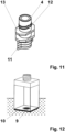
- FIG. 11 With the schematic representation of the Figure 11 the formation of a spout 4 with a molded body 13 serving for fixing is shown.
- the molded body 13 is arranged above the welding surface 11 of the stand-up pouch 2.
- the connecting part of the spout 4 located at the top has a thread 12 serving for screwing to the dosing pump 3.
- the representation of the Figure 12 shows the design of the container with a recess 9 in the container base 10.
- This recess 9 serves as a collection point for the remaining consumables.
- the stand-up pouch 2 is pressed into the recess 9 and the consumables are completely removed.
Landscapes
- Engineering & Computer Science (AREA)
- Mechanical Engineering (AREA)
- Health & Medical Sciences (AREA)
- Public Health (AREA)
- Packages (AREA)
- Containers And Packaging Bodies Having A Special Means To Remove Contents (AREA)
Description
- Die Erfindung betrifft ein Behältersystem zur Aufnahme und dosierbaren Entnahme von flüssigen Verbrauchsartikeln wie z.B. Kosmetikartikel. Dazu besteht das Behältersystem aus einem Hauptbehälter, der mit einer zur Dosierung der Verbrauchsartikel dienenden Pumpeinrichtung verbunden sowie mit aus materialsparenden, gewichtsoptimierenden und/oder vollständig recycelbarenMaterialien, insbesondere nachwachsenden Rohstoffen, bestehenden Ersatzbehältern zusammengefügt werden kann.
- Auf dem Markt angebotene Kosmetikartikel wie beispielsweise Seife, Badezusatz oder Duschgel werden überwiegend in Behältnissen aus Kunststoff oder Glas untergebracht. Neben der formgestalterisch sehr ansprechenden Form weisen diese Behältnisse häufig auch eine zur Dosierung dienende und vom Verbraucher leicht per Fingerdruck betätigbare Pumpeinrichtung auf. Nach dem Gebrauch gelangen diese Kunststoff- Behältnisse neben anderem Plastikmüll jedoch ebenfalls in beträchtlichem Maße unkontrolliert in die Umwelt und stellen ein immer größer werdendes weltweites Problem dar.
- Wie in der
DE 10 2008 030 076 A1 u.a. ausgeführt, stellen Getränkekartons eine vorteilhafte Alternative zu herkömmlichen Behältnissen aus Kunststoff oder Glas dar. Die auch als Verbundstoffverpackung bekannten Getränkekartons kommen für flüssiges oder viskoses Füllgut zur Anwendung. Insbesondere dienen sie als Verpackung für Lebensmittel, z.B. für Milch oder Fruchtsaft. Derartige Verpackungen sind unter der bekannten Bezeichnung Tetra Pak auf dem Markt. Häufig ist auf der Oberseite der Verpackung eine Öffnung mit einem zylinderförmig nach außen ragenden Teil eingebracht. Auf der Oberfläche des zylinderförmig nach außen ragenden Teiles befindet sich ein Gewinde, das mit einem ebenfalls ein Gewinde aufweisenden Verschluss verschraubt werden kann. Geeignet sind diese Verpackungen für das "Ausgießen" des Füllgutes. Im Gegensatz zu den Behältnissen aus Kunststoff oder Glas nehmen diese Verpackungen zusammengefaltet weniger Platz ein. Aufgrund ihrer standardisierten Größe sind diese Tetra Pak - Behälter zudem gut stapelbar und bieten dadurch effiziente logistische Vorteile. Weiterhin können vorteilhaft die leeren Verpackungen vor der Abfüllung in Form einer Rolle zum Abfüllbetrieb geliefert werden. Durch etablierte Entsorgungsbetriebe ist eine stoffliche Wiederverwertung der entleerten Verpackungen gegeben. Die Getränkekartons stellen zwar derzeitig ebenfalls Einwegverpackungen dar. Jedoch sind die bekannten Tetra Pak Behälter und Standbeutel die ökologisch sinnvollsten Lösungen. Einer Anwendung dieser Getränkekartons für kosmetische Artikel steht allerdings die hauptsächlich mögliche "Ausgießfunktion" entgegen. - Mit der
JP 2004-352 349 A - Bekannt ist weiterhin nach der
US 5 474 212 A ein Flüssigkeitspumpbehälter zur Aufnahme eines mit einer flüssigen Substanz gefüllten flexiblen Behälters. An der Oberseite des Beutels ist ein Auslassblock mit einer Auslassöffnung vorgesehen. Dabei dient eine Box zur Aufnahme des Beutels, die aus einem Paar Kastenkomponenten besteht, die durch Scharniere zum Öffnen und Schließen der Kastenteile miteinander verbunden sind. Die beanspruchte Kastenform und die damit vorgegebene äußere Form des Behälters sowie der damit vorgegebene innere Aufnahmeraum des Behälters für den auszutauschenden Behälter begrenzt den Anwendungsbereich des Flüssigkeitspumpbehälters auf wenige Beutelformen ein. - Bei dem durch die Druckschrift
CN 205 972 348 U beschriebenen Pumpbehälter erfolgt die Fixierung des als Beutel ausgeführten Ersatzbehälters durch einen mit dem Behälter verbundenen Bajonettverschluss. Obwohl diese Verschlussart eine einfache und sichere Verbindung zwischen den Ersatzbehälter und dem aufnehmenden Behälter darstellt, ist die Herstellung dieser Verbindungsart mit einem relativ hohen wirtschaftlichen Aufwand verbunden. - Des weiteren wird von der Druckschrift
KR 20 2011 0000 633 U - Die Aufgabe der Erfindung besteht deshalb in der Schaffung eines Behältersystems mit austauschbaren Behältern, das eine umweltschonende Aufbewahrung und Dosierung der flüssigen Verbrauchsstoffe ermöglicht undden Einsatz von Standbeuteln als Ersatzbehälter durch eine möglichst problemlose Verbindungsherstellung zwischen Standbeutel und Pumpeinrichtung vorsieht.
- Gelöst wird diese Aufgabe durch das erfindungsgemäße Behältersystem nach den beschreibenden Merkmalen des Patentanspruchs 1. Vorteilhafte Weiterbildungen des Behältersystems werden mit den Merkmalen der Patentansprüche 2 bis 7 beschrieben.
- Für das geschaffene Behältersystem kommen auswechselbare Ersatzbehälter zur Aufnahme der Verbrauchsstoffe wie z.B. Kosmetikartikel zum Einsatz, die aus wiederaufbereitbaren Materialien oder andere materialsparende und/oder gewichtsoptimierendenachwachsende Rohstoffe bestehen. Im Gegensatz zu den konventionellen Behältnissen aus Kunststoff oder Glas stellen diese Ersatzbehälter eine umweltschonende Alternative dar, die sich zudem kostensenkend auf die Logistik und den Herstellungspreis auswirkt. Vorteilhaft wird eine Verbindung der vorzugsweise aus Karton oder vollständig recycelbaren Materialien bestehenden Behälter mit Dosierungspumpen hergestellt. Dadurch werden die Vorteile einer leichten Bedienung bei der Entnahme der Kosmetikartikel mit einer umweltfreundlichen und kostengünstigen Gestaltung der Behälter effizient verbunden. Um die ansprechende gestalterische und farbliche Formgebung der konventionellen Behälter der Kosmetikartikel beizubehalten, werden die auswechselbaren Behälter alternativ in stationär vorhandenen Aufnahmevorrichtungen untergebracht. Dabei dienen die Behälter als so genannte Nachfüllpackungen. Günstig erweist sich dabei, wenn die konventionellen Behälter in ihrer hergebrachten Gestaltung in zwei zusammenfügbare Teile aufgetrennt werden. Der obere Teil ist dabei in herkömmlicher Weise mit der Dosierungspumpe verbunden. In einer weiteren Ausführungsform wird der Deckel auf den Grundbehälter aufgesetzt und danach die Dosierungspumpe aufgeschraubt. Der auswechselbare Behälter wird in den Innenraum der zusammengefügten Teile eingebracht. Bei der Zusammenfügung der Teile wird die Dosierungspumpe in die Öffnung des Behälters eingeführt. Als Nachfüllbehälter kommen vorzugsweise Standbeutel zur Anwendung. Nach der Einfügung der Standbeutel in den Innenraum des Hauptbehälters können diese aufgrund ihrer flexiblen Beschaffenheit um ihre Längsachse verdreht werden. Das während des Aufschraubvorganges der Dosierpumpe auf den Standbeutel entstehende Drehmoment überträgt sich auf den Standbodenbeutel und verdreht diesen um seine Längsachse. Um die Dosierpumpen auf die mit Gewinde versehenen Spouts der Standbeutel ohne Beschädigungen aufschrauben zu können, werden die mit den Standbeuteln verbundenen Spout durch die geschaffenen Fixierungslösungen weitestgehend in ihrer Position gehalten.
- Nachfolgend soll die Erfindung anhand eines Ausführungsbeispiels näher erläutert werden. In den Zeichnungen zeigen
-
Fig. 1 : die schematische Darstellung der Baugruppen des Behältersystems, -
Fig. 2 : die schematische Darstellung des zusammengefügten Behältersystems mit Standbeutel, -
Fig. 3 : die Fixierung mittels zylindrischer Fixierungselemente, -
Fig. 4 : die schematische seitliche Schnittdarstellungmit den zylindrischen Fixierungselementen, -
Fig. 5 : die Fixierung mittels Formkörper als Fixierungselemente, -
Fig. 6 : die schematische seitliche Schnittdarstellungmit den Formkörpern als Fixierungselemente, -
Fig. 7 : die Fixierungmittels gekrümmter Erhebungen um die Austrittsöffnung desBehälterdeckels, -
Fig. 8 : die schematische seitliche Schnittdarstellungmit dengekrümmten Erhebungenals Fixierungselemente, -
Fig. 9 : die Fixierungmittels einer im Behälterdeckel eingebrachten Austrittsöffnung, -
Fig. 10 : die schematische seitliche Schnittdarstellungmit der Austrittsöffnung alsFixierungsmittel, -
Fig. 11 :die schematische Ansicht des Spouts mit einem Formkörper als Fixierungsmittel und -
Fig. 12 : die schematische Darstellung des Behälters mit einer Vertiefung im Behälterboden. - Die schematische Darstellung der
Figur 1 zeigt die Baugruppen des Behältersystems. Es besteht aus dem Hauptbehälter 1, dem Behälterdeckel 5 und der Dosierpumpe 3. Das zusammengefügte Behältersystem mit einem allgemein bekannten Standbeutel 2 als Nachfüllpackung wird durchFigur 2 wiedergegeben. Der Standbeutel 2 wirdnach seiner Entleerung umweltschonend wieder aufbereitet.Die äußere optische Gestaltung des Behältersist bei dieser Variante mit der des Originalbehälters identisch.Auf diese Art und Weise bleibt die optisch gefällige Gestaltung des Originalbehälters erhalten. Die in derFigur 2 schematisch wiedergegebene Dosierpumpe 3 ist fest oder aufschraubbar mit dem Behälterdeckel 5 verbunden. Nach der Einfügung der Standbeutels 2 in den Innenraum des Hauptbehälters 1 kann dieser aufgrund seiner flexiblen Beschaffenheit um seine Längsachse verdreht werden. Die am oberen Ende mit dem Standbeutel 2 verbundene Ausgießform (Spout) wird, wie inFigur 3 dargestellt, durch die Austrittsöffnung 6 des Behälterdeckels 5 geführt und mittels des Gewindeadapters 8 mit der Dosierpumpe 3 verschraubt.Und die erforderliche feste Position des Standbeutels 2 während der Verschraubung zu erreichen, werden am Rand der Austrittsöffnung 6 vier Erhebungen 7 eingebracht.Zwischen den auf der Unterseite des Behälterdeckels 5 eingebrachten Erhebungen 7 wird der obere Teil des Standbeutels 2 eingefügt. Dies geschieht durch das Aufsetzen des Behälterdeckels 5 auf den Standbeutel 2. Die schematische Schnittdarstellung derFigur 4 zeigt den Behälterdeckel 5 im aufgesetzten Zustand auf den Standbeutel 2. Gezeigt werden die seitlich neben der eingeschweißten Fläche des Standbeutels 2liegenden Erhebungen 7, die das Verdrehen des Standbeutels 2 bei der Verschraubung mit der Dosierpumpe 3 verhindern. Ebenso können die Erhebungen 7 aber auch auf der der Austrittsöffnung zugewandten Einschweißfläche des Spoutes 4 angeordnet werden und in Öffnungen bzw. Vertiefungen des Behälterdeckels eingreifen. - Mit der
Figur 5 wird die schematische Anordnung eines Formkörpers 13 in der Austrittsöffnung 6 des Behälterdeckels 5 wiedergegeben. Dieser dient zur Fixierung des ebenfalls mit einem passenden Formkörpers 13 versehenen Standbeutels 2. Mit der schematischen Schnittdarstellung derFigur 6 wird der Standbeutel 2 nach der Einfügungin den Behälterdeckel 5 dargestellt.In dieser Darstellung ist die Dosierpumpe 3 mit der Ausgießform (Spout) des Standbeutels 2 verschraubt. - Eine weitere Variante der Fixierung des eingefügten Standbeutels 2 zeigt
Figur 7 . Als Fixierungselemente dienen zwei auf der Unterseite des Behälterdeckels 5 angeordnete halbrunde Erhebungen 7. Der Abstand zwischen den Erhebungen 7 ist dabei so gewählt, dass sie Raum für die Einfügung des oberen Teils des Standbeutels 2 lassen. Nach dem Aufsetzen des Behälterdeckels 5 ist der Standbeutel 2 dann zwischen den beiden Erhebungen 7 fixiert. Diesen fixierten Zustand mit der aufgeschraubten Dosierpumpe 3 gibtFigur 8 wieder. - Bei der Fixierungsvariante nach
Figur 9 wird die Austrittsöffnung 6 so gestaltet, dass der in die Austrittsöffnung 6 eingefügte Standbeutel 2 im Behälterdeckel 5 formschlüssig fixiert wird.Mit der schematischen Schnittdarstellung derFigur 10 wird dieser Fixierungszustand nach der Verschraubung der Dosierpumpe 4 mit dem Standbeutel 2 wiedergegeben. Die Verschraubung selbst erfolgt mittels des Gewindeadapters 6. - Mit der schematischen Wiedergabe der
Figur 11 wird die Ausbildung eines Spouts 4 mit einem zur Fixierung dienenden Formkörper 13 abgebildet. Der Formkörper 13 ist dabei oberhalb der Einschweißfläche 11 des Standbeutels 2 angeordnet. Das oben befindliche Verbindungsteil des Spouts4 weist ein zur Verschraubung mit der Dosierpumpe 3 dienendes Gewinde 12 auf. - Die Darstellung der
Figur 12 zeigt die Ausführung des Behälters mit einer im Behälterboden 10 eingebrachten Vertiefung 9. Diese Vertiefung 9 dient als Sammelpunkt für die Restbestände der Verbrauchsstoffe. Mittels eines entsprechend langen Saugrohres der Dosierpumpe 3 wird der Standbeutel 2 in die Vertiefung 9 gedrückt und eine vollständige Entnahme der Verbrauchsstoffe erreicht. -
- 1
- Hauptbehälter
- 2
- Standbeutel
- 3
- Dosierpumpe
- 4
- Spout
- 5
- Behälterdeckel
- 6
- Austrittsöffnung
- 7
- Erhebung
- 8
- Gewindeadapter
- 9
- Vertiefung
- 10
- Behälterboden
- 11
- Einschweißfläche
- 12
- Gewinde
- 13
- Formkörper
Claims (7)
- Behältersystem für flüssige Verbrauchsstoffe mit auswechselbaren Ersatzbehältern aus materialsparenden, gewichtsoptimierenden Materialien, insbesondere nachwachsenden und/oder vollständig recycelbaren Rohstoffen, die mit einer Dosierpumpe (3) verbindbar gestaltet sind, wobei das Behältersystem aus einem Hauptbehälter (1) besteht, in den als Ersatzbehälter dienende Standbeutel (2) bei ihrer Einbringung derart fixiert werden, dass sie nicht mehr um ihre Längsachse gedreht werden können und diese Fixierung während der Verbindungsherstellung und -lösung zwischen der Dosierpumpe und den Standbeuteln erhalten bleibt, dadurch gekennzeichnet, dass die Fixierung der Standbeutel (2) durch Einfügung von auf der Oberseite und/oder auf dem Einschweißteil von mit dem Standbeutel (2) verbundener Spouts (4) angeformten Erhebungen (7) in Aussparungen eines den Hauptbehälter (1) verschließenden Behälterdeckels (5) erfolgt.
- Behältersystem nach Patentanspruch 1, dadurch gekennzeichnet, dass die Fixierung der Standbeutel (2) durch Einfügung des Spouts (4) zwischen auf der Innenseite des Behälterdeckels (5) eingebrachten Erhebungen und/ oder Vertiefungen (7) erfolgt.
- Behältersystem nach Patentanspruch 2, dadurch gekennzeichnet, dass die Fixierung der Standbeutel (2) durch Einfügung des Spouts (4) zwischen auf der Innenseite des Behälterdeckels (5) um die Austrittsöffnung (6) herum eingebrachten zylinderförmigen Erhebungen (7) erfolgt.
- Behältersystem nach Patentanspruch 2, dadurch gekennzeichnet, dass die Fixierung der Standbeutel (2) durch Einfügung des Spouts (4) zwischen auf der Innenseite des Behälterdeckels (5) eingebrachten gekrümmt um die Austrittsöffnung (6) angeordneten Erhebungen (7) erfolgt.
- Behältersystem nach Patentanspruch 1, dadurch gekennzeichnet, dass die Dosierpumpe (3) mittels eines Gewindeadapters (8) mit dem jeweiligen Standbeutel (2) lösbar verbunden ist.
- Behältersystem nach Patentanspruch 1, dadurch gekennzeichnet, dass die Fixierung der Standbeutel (2) durch Einfügung der Spouts (4) in geformte Aussparungen des Behälterdeckels (5) erfolgt.
- Behältersystem nach Patentanspruch 1, dadurch gekennzeichnet, dass für das Behältersystem eine stationäre Aufnahmevorrichtung vorgesehen ist, die zur Aufnahme des Hauptbehälters (1) dient, in dem der die Verbrauchsstoffe enthaltende Ersatzbehälter angeordnet und über den Behälterdeckel (5) mit der Dosierpumpe (3) verbunden wird.
Applications Claiming Priority (3)
| Application Number | Priority Date | Filing Date | Title |
|---|---|---|---|
| DE102019008557.4A DE102019008557B4 (de) | 2019-12-10 | 2019-12-10 | Behältersystem für flüssige Verbrauchsmaterialien mit auswechselbaren Ersatzbehältern |
| DE202020000934.2U DE202020000934U1 (de) | 2020-03-08 | 2020-03-08 | Behältersystem für flüssige Verbrauchsmaterialien mit auswechselbaren Ersatzbehältern |
| PCT/DE2020/000217 WO2021115506A1 (de) | 2019-12-10 | 2020-09-23 | Behältersystem für flüssige verbrauchsmaterialien mit auswechselbaren ersatzbehältern |
Publications (3)
| Publication Number | Publication Date |
|---|---|
| EP4072388A1 EP4072388A1 (de) | 2022-10-19 |
| EP4072388C0 EP4072388C0 (de) | 2024-07-31 |
| EP4072388B1 true EP4072388B1 (de) | 2024-07-31 |
Family
ID=83272464
Family Applications (1)
| Application Number | Title | Priority Date | Filing Date |
|---|---|---|---|
| EP20788703.5A Active EP4072388B1 (de) | 2019-12-10 | 2020-09-23 | Behältersystem für flüssige verbrauchsmaterialien mit auswechselbaren ersatzbehältern |
Country Status (2)
| Country | Link |
|---|---|
| EP (1) | EP4072388B1 (de) |
| ES (1) | ES2990033T3 (de) |
-
2020
- 2020-09-23 EP EP20788703.5A patent/EP4072388B1/de active Active
- 2020-09-23 ES ES20788703T patent/ES2990033T3/es active Active
Also Published As
| Publication number | Publication date |
|---|---|
| EP4072388A1 (de) | 2022-10-19 |
| EP4072388C0 (de) | 2024-07-31 |
| ES2990033T3 (es) | 2024-11-28 |
Similar Documents
| Publication | Publication Date | Title |
|---|---|---|
| DE102019000187B4 (de) | Dosierbares Behältersystem für flüssige Verbrauchsmaterialien mit auswechselbaren Ersatzbehältern | |
| DE69011845T2 (de) | Austragvorrichtung mit Pumpe und einem flexiblen Nachfüllbehälter. | |
| EP0432344A1 (de) | Packung für fliessfähiges Füllgut mit umlaufender Naht | |
| DE69101191T2 (de) | Gerät zum Nachfüllen von Flaschen. | |
| DE3400931A1 (de) | Vorrichtung zum entnehmen fluessiger substanzen aus wegwerfbehaeltern mit rueckgewinnung der entnahmevorrichtung | |
| WO2013124483A2 (de) | Durchstechbarer kunststoffverschluss zum verschliessen von behältnissen | |
| EP2555995A1 (de) | PACKUNG FÜR FLIEßFÄHIGE PRODUKTE | |
| DE102019008557B4 (de) | Behältersystem für flüssige Verbrauchsmaterialien mit auswechselbaren Ersatzbehältern | |
| DE9107504U1 (de) | Nachfüllbares Verpackungssystem für flüssige oder pastöse Produkte | |
| EP4072388A1 (de) | Behältersystem für flüssige verbrauchsmaterialien mit auswechselbaren ersatzbehältern | |
| EP3099599B1 (de) | Aufsatz für eine flasche | |
| DE202020000934U1 (de) | Behältersystem für flüssige Verbrauchsmaterialien mit auswechselbaren Ersatzbehältern | |
| WO2022248483A1 (de) | Behälterverschluss | |
| DE20005766U1 (de) | Abgabevorrichtung zum Abgeben von flüssigem oder pastösem Medium | |
| WO2006122612A1 (de) | Aufsatz für flaschen zur herstellung von mischgetränken | |
| DE102015014372A1 (de) | Verschluss mit Flanschkomponente - Verschlussspund | |
| WO1994026603A1 (de) | Spundfass mit inliner | |
| DE4311141A1 (de) | Spender für fließfähige Massen | |
| DE202018004507U1 (de) | Behältervorrichtung zur Dosierung flüssiger Kosmetikartikel | |
| DE1786288B2 (de) | Verpackung, insbesondere fuer fluessige und schuettfaehige fuellgueter | |
| DE4211534A1 (de) | Behälterauskleidung | |
| DE19512477A1 (de) | Verpackungssystem aus einem permanenten Behälter und einer Nachfüllpackung | |
| DE10244349A1 (de) | Verschluss für ausgießbare Flüssigkeiten enthaltene Dosen | |
| DE202023102718U1 (de) | Behältersystem für flüssige Verbrauchsmaterialien | |
| DE19711578A1 (de) | Vorrichtung zum Öffnen und Wiederverschließen von Behältern |
Legal Events
| Date | Code | Title | Description |
|---|---|---|---|
| STAA | Information on the status of an ep patent application or granted ep patent |
Free format text: STATUS: UNKNOWN |
|
| STAA | Information on the status of an ep patent application or granted ep patent |
Free format text: STATUS: THE INTERNATIONAL PUBLICATION HAS BEEN MADE |
|
| PUAI | Public reference made under article 153(3) epc to a published international application that has entered the european phase |
Free format text: ORIGINAL CODE: 0009012 |
|
| STAA | Information on the status of an ep patent application or granted ep patent |
Free format text: STATUS: REQUEST FOR EXAMINATION WAS MADE |
|
| 17P | Request for examination filed |
Effective date: 20220708 |
|
| AK | Designated contracting states |
Kind code of ref document: A1 Designated state(s): AL AT BE BG CH CY CZ DE DK EE ES FI FR GB GR HR HU IE IS IT LI LT LU LV MC MK MT NL NO PL PT RO RS SE SI SK SM TR |
|
| DAV | Request for validation of the european patent (deleted) | ||
| DAX | Request for extension of the european patent (deleted) | ||
| GRAP | Despatch of communication of intention to grant a patent |
Free format text: ORIGINAL CODE: EPIDOSNIGR1 |
|
| STAA | Information on the status of an ep patent application or granted ep patent |
Free format text: STATUS: GRANT OF PATENT IS INTENDED |
|
| INTG | Intention to grant announced |
Effective date: 20240412 |
|
| GRAS | Grant fee paid |
Free format text: ORIGINAL CODE: EPIDOSNIGR3 |
|
| GRAA | (expected) grant |
Free format text: ORIGINAL CODE: 0009210 |
|
| STAA | Information on the status of an ep patent application or granted ep patent |
Free format text: STATUS: THE PATENT HAS BEEN GRANTED |
|
| AK | Designated contracting states |
Kind code of ref document: B1 Designated state(s): AL AT BE BG CH CY CZ DE DK EE ES FI FR GB GR HR HU IE IS IT LI LT LU LV MC MK MT NL NO PL PT RO RS SE SI SK SM TR |
|
| REG | Reference to a national code |
Ref country code: CH Ref legal event code: EP Ref country code: GB Ref legal event code: FG4D Free format text: NOT ENGLISH |
|
| REG | Reference to a national code |
Ref country code: DE Ref legal event code: R096 Ref document number: 502020008756 Country of ref document: DE |
|
| REG | Reference to a national code |
Ref country code: IE Ref legal event code: FG4D Free format text: LANGUAGE OF EP DOCUMENT: GERMAN |
|
| U01 | Request for unitary effect filed |
Effective date: 20240820 |
|
| U07 | Unitary effect registered |
Designated state(s): AT BE BG DE DK EE FI FR IT LT LU LV MT NL PT SE SI Effective date: 20240826 |
|
| U20 | Renewal fee for the european patent with unitary effect paid |
Year of fee payment: 5 Effective date: 20240904 |
|
| REG | Reference to a national code |
Ref country code: ES Ref legal event code: FG2A Ref document number: 2990033 Country of ref document: ES Kind code of ref document: T3 Effective date: 20241128 |
|
| PG25 | Lapsed in a contracting state [announced via postgrant information from national office to epo] |
Ref country code: NO Free format text: LAPSE BECAUSE OF FAILURE TO SUBMIT A TRANSLATION OF THE DESCRIPTION OR TO PAY THE FEE WITHIN THE PRESCRIBED TIME-LIMIT Effective date: 20241031 |
|
| PG25 | Lapsed in a contracting state [announced via postgrant information from national office to epo] |
Ref country code: GR Free format text: LAPSE BECAUSE OF FAILURE TO SUBMIT A TRANSLATION OF THE DESCRIPTION OR TO PAY THE FEE WITHIN THE PRESCRIBED TIME-LIMIT Effective date: 20241101 Ref country code: PL Free format text: LAPSE BECAUSE OF FAILURE TO SUBMIT A TRANSLATION OF THE DESCRIPTION OR TO PAY THE FEE WITHIN THE PRESCRIBED TIME-LIMIT Effective date: 20240731 |
|
| PG25 | Lapsed in a contracting state [announced via postgrant information from national office to epo] |
Ref country code: IS Free format text: LAPSE BECAUSE OF FAILURE TO SUBMIT A TRANSLATION OF THE DESCRIPTION OR TO PAY THE FEE WITHIN THE PRESCRIBED TIME-LIMIT Effective date: 20241130 |
|
| PG25 | Lapsed in a contracting state [announced via postgrant information from national office to epo] |
Ref country code: HR Free format text: LAPSE BECAUSE OF FAILURE TO SUBMIT A TRANSLATION OF THE DESCRIPTION OR TO PAY THE FEE WITHIN THE PRESCRIBED TIME-LIMIT Effective date: 20240731 |
|
| PG25 | Lapsed in a contracting state [announced via postgrant information from national office to epo] |
Ref country code: RS Free format text: LAPSE BECAUSE OF FAILURE TO SUBMIT A TRANSLATION OF THE DESCRIPTION OR TO PAY THE FEE WITHIN THE PRESCRIBED TIME-LIMIT Effective date: 20241031 |
|
| PG25 | Lapsed in a contracting state [announced via postgrant information from national office to epo] |
Ref country code: RS Free format text: LAPSE BECAUSE OF FAILURE TO SUBMIT A TRANSLATION OF THE DESCRIPTION OR TO PAY THE FEE WITHIN THE PRESCRIBED TIME-LIMIT Effective date: 20241031 Ref country code: PL Free format text: LAPSE BECAUSE OF FAILURE TO SUBMIT A TRANSLATION OF THE DESCRIPTION OR TO PAY THE FEE WITHIN THE PRESCRIBED TIME-LIMIT Effective date: 20240731 Ref country code: NO Free format text: LAPSE BECAUSE OF FAILURE TO SUBMIT A TRANSLATION OF THE DESCRIPTION OR TO PAY THE FEE WITHIN THE PRESCRIBED TIME-LIMIT Effective date: 20241031 Ref country code: IS Free format text: LAPSE BECAUSE OF FAILURE TO SUBMIT A TRANSLATION OF THE DESCRIPTION OR TO PAY THE FEE WITHIN THE PRESCRIBED TIME-LIMIT Effective date: 20241130 Ref country code: HR Free format text: LAPSE BECAUSE OF FAILURE TO SUBMIT A TRANSLATION OF THE DESCRIPTION OR TO PAY THE FEE WITHIN THE PRESCRIBED TIME-LIMIT Effective date: 20240731 Ref country code: GR Free format text: LAPSE BECAUSE OF FAILURE TO SUBMIT A TRANSLATION OF THE DESCRIPTION OR TO PAY THE FEE WITHIN THE PRESCRIBED TIME-LIMIT Effective date: 20241101 |
|
| PG25 | Lapsed in a contracting state [announced via postgrant information from national office to epo] |
Ref country code: SM Free format text: LAPSE BECAUSE OF FAILURE TO SUBMIT A TRANSLATION OF THE DESCRIPTION OR TO PAY THE FEE WITHIN THE PRESCRIBED TIME-LIMIT Effective date: 20240731 |
|
| U1N | Appointed representative for the unitary patent procedure changed after the registration of the unitary effect |
Representative=s name: MAIKOWSKI & NINNEMANNPATENTANWAELTE PARTNERSCHAFT MBB; DE |
|
| PG25 | Lapsed in a contracting state [announced via postgrant information from national office to epo] |
Ref country code: MC Free format text: LAPSE BECAUSE OF FAILURE TO SUBMIT A TRANSLATION OF THE DESCRIPTION OR TO PAY THE FEE WITHIN THE PRESCRIBED TIME-LIMIT Effective date: 20240731 |
|
| PG25 | Lapsed in a contracting state [announced via postgrant information from national office to epo] |
Ref country code: CZ Free format text: LAPSE BECAUSE OF FAILURE TO SUBMIT A TRANSLATION OF THE DESCRIPTION OR TO PAY THE FEE WITHIN THE PRESCRIBED TIME-LIMIT Effective date: 20240731 |
|
| PG25 | Lapsed in a contracting state [announced via postgrant information from national office to epo] |
Ref country code: SK Free format text: LAPSE BECAUSE OF FAILURE TO SUBMIT A TRANSLATION OF THE DESCRIPTION OR TO PAY THE FEE WITHIN THE PRESCRIBED TIME-LIMIT Effective date: 20240731 |
|
| PLBE | No opposition filed within time limit |
Free format text: ORIGINAL CODE: 0009261 |
|
| STAA | Information on the status of an ep patent application or granted ep patent |
Free format text: STATUS: NO OPPOSITION FILED WITHIN TIME LIMIT |
|
| 26N | No opposition filed |
Effective date: 20250501 |
|
| PG25 | Lapsed in a contracting state [announced via postgrant information from national office to epo] |
Ref country code: IE Free format text: LAPSE BECAUSE OF NON-PAYMENT OF DUE FEES Effective date: 20240923 |
|
| REG | Reference to a national code |
Ref country code: CH Ref legal event code: U11 Free format text: ST27 STATUS EVENT CODE: U-0-0-U10-U11 (AS PROVIDED BY THE NATIONAL OFFICE) Effective date: 20251001 |
|
| PGFP | Annual fee paid to national office [announced via postgrant information from national office to epo] |
Ref country code: GB Payment date: 20250923 Year of fee payment: 6 |
|
| U20 | Renewal fee for the european patent with unitary effect paid |
Year of fee payment: 6 Effective date: 20250916 |
|
| PG25 | Lapsed in a contracting state [announced via postgrant information from national office to epo] |
Ref country code: RO Free format text: LAPSE BECAUSE OF FAILURE TO SUBMIT A TRANSLATION OF THE DESCRIPTION OR TO PAY THE FEE WITHIN THE PRESCRIBED TIME-LIMIT Effective date: 20240731 |
|
| PGFP | Annual fee paid to national office [announced via postgrant information from national office to epo] |
Ref country code: CH Payment date: 20251001 Year of fee payment: 6 |
|
| PG25 | Lapsed in a contracting state [announced via postgrant information from national office to epo] |
Ref country code: CY Free format text: LAPSE BECAUSE OF FAILURE TO SUBMIT A TRANSLATION OF THE DESCRIPTION OR TO PAY THE FEE WITHIN THE PRESCRIBED TIME-LIMIT; INVALID AB INITIO Effective date: 20200923 |
|
| PGFP | Annual fee paid to national office [announced via postgrant information from national office to epo] |
Ref country code: ES Payment date: 20251020 Year of fee payment: 6 |
|
| PG25 | Lapsed in a contracting state [announced via postgrant information from national office to epo] |
Ref country code: HU Free format text: LAPSE BECAUSE OF FAILURE TO SUBMIT A TRANSLATION OF THE DESCRIPTION OR TO PAY THE FEE WITHIN THE PRESCRIBED TIME-LIMIT; INVALID AB INITIO Effective date: 20200923 |