EP4071484A1 - Automatisierter analysator - Google Patents
Automatisierter analysator Download PDFInfo
- Publication number
- EP4071484A1 EP4071484A1 EP20895734.0A EP20895734A EP4071484A1 EP 4071484 A1 EP4071484 A1 EP 4071484A1 EP 20895734 A EP20895734 A EP 20895734A EP 4071484 A1 EP4071484 A1 EP 4071484A1
- Authority
- EP
- European Patent Office
- Prior art keywords
- nozzle
- period
- mixed liquid
- during
- speed
- Prior art date
- Legal status (The legal status is an assumption and is not a legal conclusion. Google has not performed a legal analysis and makes no representation as to the accuracy of the status listed.)
- Granted
Links
Images


Classifications
-
- G—PHYSICS
- G01—MEASURING; TESTING
- G01N—INVESTIGATING OR ANALYSING MATERIALS BY DETERMINING THEIR CHEMICAL OR PHYSICAL PROPERTIES
- G01N35/00—Automatic analysis not limited to methods or materials provided for in any single one of groups G01N1/00 - G01N33/00; Handling materials therefor
- G01N35/10—Devices for transferring samples or any liquids to, in, or from, the analysis apparatus, e.g. suction devices, injection devices
- G01N35/1009—Characterised by arrangements for controlling the aspiration or dispense of liquids
-
- G—PHYSICS
- G01—MEASURING; TESTING
- G01N—INVESTIGATING OR ANALYSING MATERIALS BY DETERMINING THEIR CHEMICAL OR PHYSICAL PROPERTIES
- G01N35/00—Automatic analysis not limited to methods or materials provided for in any single one of groups G01N1/00 - G01N33/00; Handling materials therefor
- G01N35/02—Automatic analysis not limited to methods or materials provided for in any single one of groups G01N1/00 - G01N33/00; Handling materials therefor using a plurality of sample containers moved by a conveyor system past one or more treatment or analysis stations
-
- G—PHYSICS
- G01—MEASURING; TESTING
- G01N—INVESTIGATING OR ANALYSING MATERIALS BY DETERMINING THEIR CHEMICAL OR PHYSICAL PROPERTIES
- G01N35/00—Automatic analysis not limited to methods or materials provided for in any single one of groups G01N1/00 - G01N33/00; Handling materials therefor
- G01N35/00584—Control arrangements for automatic analysers
-
- G—PHYSICS
- G01—MEASURING; TESTING
- G01N—INVESTIGATING OR ANALYSING MATERIALS BY DETERMINING THEIR CHEMICAL OR PHYSICAL PROPERTIES
- G01N35/00—Automatic analysis not limited to methods or materials provided for in any single one of groups G01N1/00 - G01N33/00; Handling materials therefor
- G01N35/10—Devices for transferring samples or any liquids to, in, or from, the analysis apparatus, e.g. suction devices, injection devices
- G01N35/1009—Characterised by arrangements for controlling the aspiration or dispense of liquids
- G01N35/1011—Control of the position or alignment of the transfer device
-
- G—PHYSICS
- G01—MEASURING; TESTING
- G01N—INVESTIGATING OR ANALYSING MATERIALS BY DETERMINING THEIR CHEMICAL OR PHYSICAL PROPERTIES
- G01N35/00—Automatic analysis not limited to methods or materials provided for in any single one of groups G01N1/00 - G01N33/00; Handling materials therefor
- G01N2035/00346—Heating or cooling arrangements
- G01N2035/00356—Holding samples at elevated temperature (incubation)
-
- G—PHYSICS
- G01—MEASURING; TESTING
- G01N—INVESTIGATING OR ANALYSING MATERIALS BY DETERMINING THEIR CHEMICAL OR PHYSICAL PROPERTIES
- G01N35/00—Automatic analysis not limited to methods or materials provided for in any single one of groups G01N1/00 - G01N33/00; Handling materials therefor
- G01N2035/00465—Separating and mixing arrangements
- G01N2035/00534—Mixing by a special element, e.g. stirrer
- G01N2035/00544—Mixing by a special element, e.g. stirrer using fluid flow
-
- G—PHYSICS
- G01—MEASURING; TESTING
- G01N—INVESTIGATING OR ANALYSING MATERIALS BY DETERMINING THEIR CHEMICAL OR PHYSICAL PROPERTIES
- G01N35/00—Automatic analysis not limited to methods or materials provided for in any single one of groups G01N1/00 - G01N33/00; Handling materials therefor
- G01N35/10—Devices for transferring samples or any liquids to, in, or from, the analysis apparatus, e.g. suction devices, injection devices
- G01N35/1009—Characterised by arrangements for controlling the aspiration or dispense of liquids
- G01N35/1016—Control of the volume dispensed or introduced
- G01N2035/102—Preventing or detecting loss of fluid by dripping
- G01N2035/1023—Preventing or detecting loss of fluid by dripping using a valve in the tip or nozzle
-
- G—PHYSICS
- G01—MEASURING; TESTING
- G01N—INVESTIGATING OR ANALYSING MATERIALS BY DETERMINING THEIR CHEMICAL OR PHYSICAL PROPERTIES
- G01N35/00—Automatic analysis not limited to methods or materials provided for in any single one of groups G01N1/00 - G01N33/00; Handling materials therefor
- G01N35/10—Devices for transferring samples or any liquids to, in, or from, the analysis apparatus, e.g. suction devices, injection devices
- G01N2035/1027—General features of the devices
- G01N2035/1048—General features of the devices using the transfer device for another function
- G01N2035/1058—General features of the devices using the transfer device for another function for mixing
- G01N2035/106—General features of the devices using the transfer device for another function for mixing by sucking and blowing
Definitions
- the present invention relates to an automatic analysis device that executes qualitative and quantitative analysis of a specific component contained in a biological sample such as blood or urine.
- an automatic analysis device a biochemical analysis device that analyzes a biological component contained in a specimen (sample) such as blood and urine, and an immunoassay analysis device are known.
- the automatic analysis device optically measures a concentration of a mixed liquid generated by a reaction between a sample and a mixed liquid used for analysis of each inspection item, activity of an enzyme, and the like.
- PTL 1 and PTL 2 disclose that at least a part of a mixed liquid in a reaction vessel (adjustment vessel) is suctioned into a dispensing nozzle and is then discharged into the reaction vessel (adjustment vessel) to agitate the mixed liquid (hereinafter, referred to as nozzle agitation).
- PTL 1 does not disclose details of a suction operation and a discharge operation in the nozzle agitation.
- PTL 2 discloses the nozzle agitation by using a disposable nozzle, and discloses that in a nozzle agitation step, suction is executed at a position where a nozzle tip is brought into contact with or close to a bottom of the adjustment vessel, and at the time of discharge, the nozzle tip discharges a liquid near a liquid surface after the discharge.
- a speed at which the nozzle discharges the mixed liquid is variable in accordance with a surface tension or viscosity of the liquid.
- the nozzle is descended to immerse the nozzle tip in the liquid to be suctioned. At this time, a liquid amount varies depending on an object to be measured, and thus a height of the liquid surface varies.
- a nozzle other than the disposable nozzle it is necessary to clean the immersed nozzle tip in order to prevent contamination. Therefore, when immersing the nozzle in the liquid, liquid surface detection is executed, and the nozzle is immersed to a certain depth based on the detected liquid surface. An immersion depth of the nozzle tip is determined as a depth at which a detection variation is absorbed and a cleaning range is not increased too much.
- a method of executing the liquid surface detection there is a method of detecting the liquid surface by electrostatic capacity, ultrasonic wave, or the like.
- Inventors of the invention have found that immersing a nozzle tip portion in a mixed liquid at the time of nozzle agitation hinders uniformity of the mixed liquid due to the nozzle agitation.
- the reason is that since the mixed liquid above the tip of the nozzle is not suctioned, agitation of the mixed liquid above the tip of the nozzle is difficult to proceed, a flow of a liquid to be agitated is difficult to be generated near a side surface of the nozzle at the time of re-discharging, and agitation near the side surface of the nozzle is difficult to proceed.
- An object of the invention is to enhance the uniformity of the mixed liquid in the reaction vessel due to the nozzle agitation by vigorously agitating the mixed liquid near the liquid surface of the reaction vessel, in particular, at a depth at which the nozzle tip is immersed at the time of suction.
- An automatic analysis device includes: an incubator in which a reaction vessel is arranged; a dispensing mechanism that includes a nozzle movable upward or downward and dispenses a sample or a reagent into the reaction vessel; and a control unit that controls the dispensing mechanism to agitate a mixed liquid of the sample and the reagent in the reaction vessel.
- the dispensing mechanism agitates the mixed liquid by suctioning the mixed liquid in the reaction vessel by the nozzle and then re-discharging the suctioned mixed liquid into the reaction vessel, and when re-discharging the mixed liquid into the reaction vessel, the control unit moves the nozzle upward at a speed higher than a speed at which a liquid surface of the mixed liquid rises due to the re-discharging of the mixed liquid from the nozzle, during a first period, and lowers the speed of moving the nozzle upward than the speed during the first period while maintaining or reducing the speed at which the liquid surface of the mixed liquid rises due to re-discharging of the mixed liquid from the nozzle, during a second period following the first period.
- An automatic analysis device in which uniformity of a mixed liquid due to nozzle agitation by a dispensing mechanism is enhanced.
- Fig. 1 schematically shows an overall configuration of an automatic analysis device.
- reaction vessels 2 are arranged on a circumferential position of an incubator 1.
- the reaction vessels 2 are used common for all reactions, and the reaction vessels 2 are disposable.
- the reaction vessels 2 are stored in a reaction vessel tray 20, and are supplied to the incubator 1 by a dispensing tip/reaction vessel transport mechanism 17.
- the incubator 1 is controlled by a driving mechanism such as a motor so as to be rotationally driven by a distance corresponding to arrangement positions of a predetermined number of reaction vessels in one cycle.
- a plurality of reagent bottles 4 and sample vessels 5 can be placed in a common storage unit of reagent and sample 3.
- the reagent bottles 4 are located on an inner periphery of the sample vessels 5.
- the sample vessels 5 may be located on an inner periphery of the reagent bottles 4, or the reagent bottles 4 and the sample vessels 5 may be located separately in a circumferential direction instead of a radial direction.
- Pumps 10 and 11 are connected to the dispensing nozzles.
- the first dispensing mechanism 8 and the second dispensing mechanism 9 are selectively used for inspections in different analysis processes. For example, when the first dispensing mechanism 8 is for biochemical use and the second dispensing mechanism 9 is for immunological use, the first dispensing mechanism 8 dispenses a sample and a reagent for biochemical inspection, and the second dispensing mechanism 9 dispenses a sample and a reagent for immunological inspection. For a sample to be subjected to both the biochemical inspection and the immunological inspection, the first dispensing mechanism 8 accesses and dispenses the sample during the biochemical inspection, and the second dispensing mechanism 9 accesses and dispenses the sample during the immunological inspection.
- dispensing tips 18 are mounted to the dispensing nozzle at the time of dispensing.
- the dispensing tips 18 are stored in a dispensing tip tray 19, supplied to a dispensing tip mounting position 22 by the dispensing tip/reaction vessel transport mechanism 17, and mounted on the dispensing nozzle at the dispensing tip mounting position 22.
- the dispensing nozzle moves while drawing an arc around a rotation axis, and dispenses the sample from the sample vessel to the reaction vessel.
- Reagent suction positions 6 and sample suction positions 7 on the common storage unit of reagent and sample 3, a first dispensing position and a second dispensing position on the incubator 1, and a cleaning tank 12 (13) for cleaning the dispensing nozzle are present on a trajectory of each dispensing nozzle. Since the dispensing tips are used in the second dispensing mechanism 9, the dispensing tip mounting position 22 and a dispensing tip disposal position 23 are also present on the trajectory in addition to those described above.
- the first dispensing mechanism 8 and the second dispensing mechanism 9 need to be arranged such that trajectories of respective dispensing nozzles and the mechanisms do not physically interfere with one another.
- the sample and the reagent are suctioned by the dispensing nozzle during the biochemical inspection and are suctioned by the dispensing tip mounted to the dispensing nozzle during the immunological inspection, and the sample and the reagent are agitated and mixed by suction and discharge operations by the dispensing nozzle or the dispensing tip in the reaction vessel 2.
- an agitating mechanism that agitates the sample and the reagent is not necessary.
- the reaction vessel 2 that accommodates a reaction liquid in which the sample and the reagent are mixed is controlled to a predetermined temperature by the incubator 1, and a reaction is promoted for a predetermined time.
- a spectrophotometer 15 for biochemical inspection is arranged around the incubator 1.
- the spectrophotometer 15 includes a light source and a detector (which are not shown), and measures absorbance of the reaction liquid by spectrally detecting a transmitted light obtained by irradiating the reaction liquid in which the sample and the reagent are mixed with the light source.
- the reaction liquid reacted for a predetermined time by the incubator 1 is measured by a detection mechanism 16 for immunological inspection.
- immunological inspection as a method of detecting a labeling substance, there is a method using electrochemical luminescence or chemical luminescence as a principle. Structures and physical properties of a second liquid, the labeling substance, and a detection region suitable for each method are selected, and an amount of luminescence derived from a luminescence reaction of the labeling substance is measured using a photomultiplier tube as a detector.
- the reaction vessel 2 in which measurement of absorbance is completed in the incubator 1 is disposed into a dispensing tip/reaction vessel disposal box 21 by the dispensing tip/reaction vessel transport mechanism 17.
- the dispensing tip/reaction vessel transport mechanism 17 also moves the reaction vessel 2 that accommodates the reaction liquid reacted for a predetermined time by the incubator 1 to the detection mechanism 16 and moves the reaction vessel 2 in which measurement by the detection mechanism 16 is completed to the dispensing tip/reaction vessel disposal box 21.
- Each mechanism of the automatic analysis device is connected to a control unit 28.
- the control unit 28 controls various mechanisms that executes rotation drive of the incubator, rotation operation inside the common storage unit of reagent and sample, drive of a sample nozzle, sample suction operation, sample discharge operation, and the like.
- connection between each mechanism constituting the automatic analysis device and the control unit is omitted.
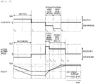
- Fig. 2 shows a procedure of nozzle agitation. Since agitation by the dispensing nozzle and nozzle agitation by the dispensing tip are executed in the same manner, hereinafter, both of the dispensing nozzle and the dispensing tip are collectively referred to as a nozzle.
- S01 shows a state in which a sample and a reagent are separately dispensed into a reaction vessel 102 by a nozzle 101, and a mixed liquid 103 of the sample and the reagent is accommodated in the reaction vessel 102. Subsequently, the nozzle is descended toward the mixed liquid 103, and a tip of the nozzle 101 is immersed in the mixed liquid 103 by about 3 mm (S02).
- the mixed liquid 103 is suctioned while the nozzle 101 is descended (hereinafter, referred to as "re-suction", S03). Subsequently, the mixed liquid 103 is discharged into the reaction vessel 102 while the nozzle 101 is ascended (hereinafter, referred to as "re-discharging", S04).
- the above-described dispensing operation, re-suction operation, and re-discharging operation may be executed by driving a syringe, and the re-suction operation and the re-discharging operation may be repeated a plurality of times as necessary.
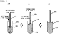
- Fig. 3 shows an example of drive control of nozzle agitation according to Embodiment 1.
- a time chart C01 shows a flow rate at which the nozzle suctions or discharges a mixed liquid in the nozzle agitation.
- a flow rate during re-discharging of the mixed liquid is set to two stages including high speed discharging and low speed discharging. Specifically, re-suction of the mixed liquid is executed (time points T 0 to T 1 ) and then stopped (time points T 1 to T 2 ).
- a time chart C02 shows a nozzle moving speed
- a time chart C03 shows a relationship between a height of a liquid surface of the mixed liquid in the reaction vessel and a height of the nozzle tip in association with the movement of the nozzle.
- the nozzle is ascended at a high speed in a re-discharging period (time points T 2 to T 3 ) under the high speed discharging
- the nozzle is ascended at a low speed in a re-discharging period (time points T 3 to T 4 ) under the low speed discharging.
- an ascending speed of the nozzle in a high speed ascending period (time points T 2 to T 3 ) is set to be higher than an ascending speed of the liquid surface, and is determined as a speed at which the tip of the nozzle is located near the liquid surface at the end of the high speed ascending period (time point T 3 ).
- the ascending speed of the nozzle in a low speed ascending period (time points T 3 to T 4 ) to be equal to the ascending speed of the liquid surface, the tip of the nozzle continues to be located near the liquid surface all the time in the re-discharging period (time points T 3 to T 4 ) under the low speed discharging.
- the movement of the nozzle is controlled by the control unit of the automatic analysis device.
- the control unit detects the liquid surface by a liquid surface detection mechanism provided in the dispensing mechanism while descending the nozzle above the liquid surface before start of the re-suction (before time point T 0 ), and stops the nozzle when the nozzle is descended to a certain depth from the liquid surface.
- control values of the ascending speed and the time of the nozzle are given to the control unit in advance according to a displacement of the height of the liquid surface of the mixed liquid by a specified flow rate (the time chart C01), and the control unit controls the operation of the nozzle according to the control values.
- the control unit controls the operation of the nozzle according to the control values.
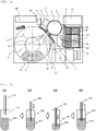
- Fig. 4 is a diagram schematically showing a state in which a mixed liquid is agitated.
- a lower portion of the mixed liquid 103 is mainly agitated by a flow of a liquid generated by discharging the mixed liquid 103 from the nozzle 101 at a high speed (S11).
- an upper portion of the mixed liquid 103 is mainly agitated by a flow of a liquid generated by discharging, at a low speed, the mixed liquid 103 from the nozzle 101 that is located near the liquid surface (S12).
- the height of the nozzle tip during the low speed discharging may be close to the height of the liquid surface, and the height of the nozzle tip may be lower than the height of the liquid surface, may be the same as the height of the liquid surface, or may be higher than the height of the liquid surface.
- the lower the height of the nozzle tip is lower than the height of the liquid surface, the more difficult it is to agitate the liquid near the liquid surface. Therefore, the height of the nozzle tip needs to be at a position higher than the height of the nozzle tip at least at the time of suction.
- the height of the nozzle tip needs to be set to a height at which the mixed liquid is not interrupted. The same applies to the following embodiments.
- Fig. 5 shows an example of drive control of nozzle agitation according to Embodiment 2.
- a time chart C11 shows a flow rate at which the nozzle suctions or discharges the mixed liquid in the nozzle agitation.
- the flow rate during re-discharging of the mixed liquid is set to two stages including high speed discharging and low speed discharging, but an order thereof is different from that in Embodiment 1. Specifically, re-suction of the mixed liquid is executed (time points T 10 to Tn) and then stopped (time points T 11 to T 12 ).
- a time chart C12 shows a nozzle moving speed
- a time chart C13 shows a relationship between a height of a liquid surface of the mixed liquid in the reaction vessel and a height of the nozzle tip in association with the movement of the nozzle.
- the nozzle is ascended at a high speed in an initial stage (time points T 12 to T 15 ) of a re-discharging period (time points T 12 to T 13 ) under the low speed discharging
- the nozzle is ascended at a low speed in a later stage (time points T 15 to T 13 ) of the re-discharging period under the low speed discharging and in the re-discharging period (time points T 13 to T 14 ) under the high speed discharging.
- the nozzle tip reaches the liquid surface at the time point T 16 .
- An ascending speed of the nozzle in a high speed ascending period (time points T 12 to T 15 ) is set to be higher than an ascending speed of the liquid surface, and is determined as a speed at which the tip of the nozzle is located near the liquid surface at the end of the high speed ascending period (time point T 15 ).
- the ascending speed of the nozzle in a low speed ascending period (time points T 15 to T 14 ) to be equal to the ascending speed of the liquid surface in the later stage (time points T 15 to T 13 ) of the re-discharging period under the low speed discharging, the tip of the nozzle continues to be located near the liquid surface all the time during that period.
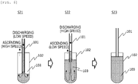
- Fig. 6 is a diagram schematically showing a state in which a mixed liquid is agitated.
- the nozzle tip moves to a position near the liquid surface in the initial stage of the low speed discharging, and the upper portion of the mixed liquid 103, particularly the position near the liquid surface, is mainly agitated by a flow of a liquid generated by discharging the mixed liquid 103 at a low speed from the nozzle 101 that is located near the liquid surface in the later stage of the low speed discharging (S21).
- the lower portion of the mixed liquid 103 is mainly agitated by the flow of the liquid generated by discharging the mixed liquid 103 from the nozzle 101 at a high speed (S22) .
- Embodiment 2 since the nozzle is ascended at a low speed in the re-discharging period (time points T 13 to T 14 ) under the high speed discharging, the nozzle tip is located below the liquid surface at the time point T 14 , but when a difference between the height of the nozzle tip and the height of the liquid surface at this time is controlled to be equal to or less than a difference in height at the time of re-suction, a cleaning range of the nozzle does not expand.
- the height of the nozzle tip is set to be at least equal to or lower than the height of the liquid surface at the time point T 13 .
- Fig. 7 shows an example of drive control of nozzle agitation according to Embodiment 3.
- a time chart C21 shows a flow rate at which the nozzle suctions or discharges the mixed liquid in the nozzle agitation.
- the mixed liquid is discharged at a constant discharge flow rate per unit time (hereinafter, referred to as high speed discharging because it is assumed that this re-discharging corresponds to the high speed discharging in Embodiments 1 and 2), and then the mixed liquid is discharged while the discharge flow rate per unit time is reduced.
- re-suction of the mixed liquid is executed (time points T 20 to T 21 ) and then stopped (time points T 21 to T 22 ).
- a time chart C22 shows a nozzle moving speed
- a time chart C23 shows a relationship between a height of a liquid surface of the mixed liquid in the reaction vessel and a height of the nozzle tip in association with the movement of the nozzle.
- the nozzle is ascended at a high speed in a re-discharging period (time points T 22 to T 23 ) under the high speed discharging, and the nozzle is ascended at a low speed in a re-discharging period (time points T 23 to T 24 ) during the speed reduction.
- An ascending speed of the nozzle in a high speed ascending period (time points T 22 to T 23 ) is set to be higher than an ascending speed of the liquid surface, and is determined as a speed at which the tip of the nozzle is located near the liquid surface at the end of the high speed ascending period (time point T 23 ).
- An ascending speed of the nozzle in a low speed ascending period (time points T 23 to T 24 ) is determined as a speed at which the tip of the nozzle is located near the liquid surface at the end of the low speed ascending period (time point T 24 ).
- Fig. 8 is a diagram schematically showing a state in which a mixed liquid is agitated.
- a lower portion of the mixed liquid 103 is mainly agitated by a flow of a liquid generated by discharging the mixed liquid 103 from the nozzle 101 at a high speed (S31).
- an upper portion of the mixed liquid 103 is mainly agitated by a flow of a liquid generated by reducing the speed and discharging the mixed liquid 103 from the nozzle 101 that is located near the liquid surface during speed reduction (S32).
- Embodiment 3 since the flow rate in the re-discharging is set to one stage, set parameters are smaller than those in Embodiment 1 and Embodiment 2, and mounting is easy. It is necessary to set the nozzle moving speed so as to minimize the deviation between the tip of the nozzle and the liquid surface generated in the discharging during speed reduction.
- FIG. 9 is a diagram showing an analysis model used for computational fluid analysis.
- the analysis model includes a nozzle 201 and a reaction vessel 202, and as an initial state, the nozzle 201 is provided with a sample 203 and a reagent 204.
- a flow speed as a boundary condition to an upper surface of the nozzle 201
- a state in which a solution is discharged from the nozzle 201 or the solution is suctioned into the nozzle 201 is analyzed.
- a movement of the nozzle 201 to an analysis condition a state in which the nozzle 201 is descended or ascended is analyzed.
- Figs. 10A and 10B show analysis results. The analysis is executed on conditions of the flow rate and the nozzle moving speed according to Embodiment 1 (see Fig. 3 ) and a comparative example.
- a flow rate and a nozzle moving speed at the time of re-discharging are constant. Therefore, in the comparative example, a constant distance is maintained between the liquid surface and the nozzle tip in a re-discharging period.
- Figs. 10A and 10B plot a relationship between a time and a coefficient of variation (CV) value of a sample concentration in the reaction vessel.
- a graph 301 shows an analysis result of the comparative example, and a graph 302 shows an analysis result of Embodiment 1.
- the CV value is an index indicating a variation in sample concentration, and is calculated by a ratio (standard deviation/average value) between an average value and a standard deviation of the sample concentration calculated in each analysis cell in the reaction vessel 202.
- Fig. 10B is an enlarged view of a period of time 1 s to 1.5 s.
- the CV value of Embodiment 1 (302) is smaller than that of the comparative example (301), that is, it can be seen that the liquid is more uniformly agitated in Embodiment 1 than in the comparative example.
- the embodiments of the invention have been described above.
- the invention is not limited to the embodiments described above, and includes various modifications.
- the dispensing mechanism that executes the nozzle agitation a dispensing mechanism that dispenses both a sample and a reagent is exemplified, but the nozzle agitation can be executed by a dispensing mechanism that dispenses the sample or the reagent.
- the embodiments have been described in detail for easy understanding of the invention, and the invention is not necessarily limited to those including all of the configurations described above.
- a part of a configuration of a certain embodiment may be replaced with a configuration of another embodiment, and a configuration of a certain embodiment may also be added with a configuration of another embodiment.
- a part of a configuration of each embodiment may be added, deleted, or replaced with another configuration.
Landscapes
- Physics & Mathematics (AREA)
- Health & Medical Sciences (AREA)
- Life Sciences & Earth Sciences (AREA)
- Chemical & Material Sciences (AREA)
- Analytical Chemistry (AREA)
- Biochemistry (AREA)
- General Health & Medical Sciences (AREA)
- General Physics & Mathematics (AREA)
- Immunology (AREA)
- Pathology (AREA)
- Automatic Analysis And Handling Materials Therefor (AREA)
Applications Claiming Priority (2)
| Application Number | Priority Date | Filing Date | Title |
|---|---|---|---|
| JP2019221061A JP7292195B2 (ja) | 2019-12-06 | 2019-12-06 | 自動分析装置 |
| PCT/JP2020/039517 WO2021111754A1 (ja) | 2019-12-06 | 2020-10-21 | 自動分析装置 |
Publications (3)
| Publication Number | Publication Date |
|---|---|
| EP4071484A1 true EP4071484A1 (de) | 2022-10-12 |
| EP4071484A4 EP4071484A4 (de) | 2023-12-27 |
| EP4071484B1 EP4071484B1 (de) | 2024-09-11 |
Family
ID=76219986
Family Applications (1)
| Application Number | Title | Priority Date | Filing Date |
|---|---|---|---|
| EP20895734.0A Active EP4071484B1 (de) | 2019-12-06 | 2020-10-21 | Automatisierter analysator |
Country Status (5)
| Country | Link |
|---|---|
| US (1) | US12504437B2 (de) |
| EP (1) | EP4071484B1 (de) |
| JP (1) | JP7292195B2 (de) |
| CN (1) | CN114729952B (de) |
| WO (1) | WO2021111754A1 (de) |
Families Citing this family (5)
| Publication number | Priority date | Publication date | Assignee | Title |
|---|---|---|---|---|
| WO2018235383A1 (ja) * | 2017-06-21 | 2018-12-27 | ソニー株式会社 | サンプル送液装置、フローサイトメータ、およびサンプル送液方法 |
| JP7305891B2 (ja) * | 2020-06-01 | 2023-07-10 | 株式会社日立ハイテク | 自動分析装置 |
| US20220268796A1 (en) * | 2021-02-19 | 2022-08-25 | Roche Molecular Systems, Inc. | Method of Operating a Laboratory Instrument |
| WO2025142477A1 (ja) * | 2023-12-29 | 2025-07-03 | 株式会社日立ハイテク | 自動分析装置、及び自動分析装置の液体攪拌方法 |
| WO2025169672A1 (ja) * | 2024-02-09 | 2025-08-14 | 富士フイルム株式会社 | 検査装置、検査装置の作動方法及び検査装置の作動プログラム |
Family Cites Families (24)
| Publication number | Priority date | Publication date | Assignee | Title |
|---|---|---|---|---|
| JPS58196461A (ja) * | 1982-05-12 | 1983-11-15 | Olympus Optical Co Ltd | 化学分析用検液の撹拌方法 |
| US4586546A (en) * | 1984-10-23 | 1986-05-06 | Cetus Corporation | Liquid handling device and method |
| JPS62184357A (ja) * | 1986-02-07 | 1987-08-12 | Seiko Instr & Electronics Ltd | ピペツトによる液体の撹拌方法 |
| JPS6366466A (ja) | 1986-09-08 | 1988-03-25 | Shimadzu Corp | デイスクリ−ト型自動分析装置 |
| JP3043510B2 (ja) * | 1992-02-05 | 2000-05-22 | シスメックス株式会社 | 試料攪拌吸引装置 |
| DE4232096A1 (de) * | 1992-09-25 | 1994-03-31 | Boehringer Mannheim Gmbh | Verfahren und Vorrichtung zum berührungslosen automatischen Mischen eines Reaktionsgemisches in einem Analysegerät |
| JP3149295B2 (ja) * | 1993-08-11 | 2001-03-26 | アロカ株式会社 | ノズルチップによる2液攪拌方法 |
| JPH08313536A (ja) * | 1995-05-17 | 1996-11-29 | Hitachi Ltd | 分析装置 |
| TW384398B (en) * | 1995-12-19 | 2000-03-11 | Toa Medical Electronics | Sample agitating and sucking apparatus |
| JPH11304817A (ja) * | 1998-04-27 | 1999-11-05 | Shimadzu Corp | 分注装置 |
| JP4203469B2 (ja) * | 2004-12-24 | 2009-01-07 | アロカ株式会社 | 液体試料の攪拌装置 |
| JP2007132855A (ja) * | 2005-11-11 | 2007-05-31 | Aloka Co Ltd | 液体攪拌方法及び装置 |
| DE102006017360A1 (de) * | 2006-04-11 | 2007-10-18 | Diasys Diagnostic Systems Gmbh | Verfahren zum Dosieren und Mischen |
| JP5222784B2 (ja) * | 2009-05-22 | 2013-06-26 | 株式会社日立ハイテクノロジーズ | 液体のサンプリング方法、及び自動分析装置 |
| JP5570848B2 (ja) * | 2010-03-05 | 2014-08-13 | 株式会社東芝 | 自動分析装置 |
| EP2937700B1 (de) * | 2012-12-19 | 2020-03-11 | Hitachi High-Technologies Corporation | Automatisierter analysator |
| JP2014126415A (ja) * | 2012-12-26 | 2014-07-07 | Hitachi High-Technologies Corp | 自動分析装置 |
| JP2015132521A (ja) * | 2014-01-10 | 2015-07-23 | 株式会社日立ハイテクノロジーズ | 溶液調製システム |
| EP3553529B1 (de) * | 2016-12-12 | 2022-10-19 | Hitachi High-Tech Corporation | Vorrichtung zur automatischen analyse und verfahren zur automatischen analyse |
| US11353473B2 (en) * | 2016-12-13 | 2022-06-07 | Hitachi High-Tech Corporation | Automatic analyzer and automatic analysis method |
| GB201704760D0 (en) * | 2017-01-05 | 2017-05-10 | Illumina Inc | Reagent nozzle sipper mixing system and method |
| JP7177596B2 (ja) * | 2018-02-27 | 2022-11-24 | シスメックス株式会社 | 検体測定装置及び検体測定方法 |
| JP6814171B2 (ja) | 2018-03-19 | 2021-01-13 | 株式会社日立ハイテク | 自動分析装置 |
| CN112639487B (zh) * | 2018-09-27 | 2024-03-08 | 株式会社日立高新技术 | 自动分析装置和清洗方法 |
-
2019
- 2019-12-06 JP JP2019221061A patent/JP7292195B2/ja active Active
-
2020
- 2020-10-21 US US17/775,409 patent/US12504437B2/en active Active
- 2020-10-21 WO PCT/JP2020/039517 patent/WO2021111754A1/ja not_active Ceased
- 2020-10-21 EP EP20895734.0A patent/EP4071484B1/de active Active
- 2020-10-21 CN CN202080080882.0A patent/CN114729952B/zh active Active
Also Published As
| Publication number | Publication date |
|---|---|
| US20220397582A1 (en) | 2022-12-15 |
| EP4071484B1 (de) | 2024-09-11 |
| WO2021111754A1 (ja) | 2021-06-10 |
| CN114729952A (zh) | 2022-07-08 |
| EP4071484A4 (de) | 2023-12-27 |
| CN114729952B (zh) | 2026-03-03 |
| JP7292195B2 (ja) | 2023-06-16 |
| JP2021089253A (ja) | 2021-06-10 |
| US12504437B2 (en) | 2025-12-23 |
Similar Documents
| Publication | Publication Date | Title |
|---|---|---|
| EP4071484B1 (de) | Automatisierter analysator | |
| CN113811773B (zh) | 自动分析装置及其清洗方法 | |
| JP6647288B2 (ja) | 自動分析装置及び方法 | |
| JP7305891B2 (ja) | 自動分析装置 | |
| CN102192997B (zh) | 自动分析装置 | |
| JP4251627B2 (ja) | 化学分析装置及びその分注方法 | |
| WO2011074273A1 (ja) | 自動分析装置 | |
| JP6227441B2 (ja) | 分析装置及びその方法 | |
| WO2022176556A1 (ja) | 自動分析装置、および自動分析装置における検体の吸引方法 | |
| JP7777221B2 (ja) | 自動分析装置およびその制御方法 | |
| JP2002340913A (ja) | 自動分析装置 | |
| CN110320380B (zh) | 自动分析装置和自动分析方法 | |
| JP2010271203A (ja) | 液体のサンプリング方法、及び自動分析装置 | |
| JP5259550B2 (ja) | 自動分析装置およびサンプル分注方法 | |
| WO2021215068A1 (ja) | 分注装置、自動分析装置、分注方法 | |
| JP7499881B2 (ja) | 自動分析装置 | |
| CN112834771B (zh) | 自动分析装置 | |
| JP2015137975A (ja) | 自動分析装置および試薬分注方法 | |
| JP2012021892A (ja) | 自動分析装置及び分注方法 | |
| JPH10153601A (ja) | 自動分析装置 | |
| EP4700392A1 (de) | Automatische analysevorrichtung und automatisches analyseverfahren | |
| JP2010151711A (ja) | 自動分析装置 | |
| JP2016040535A (ja) | 自動分析装置および自動分析装置の制御方法 | |
| JPH10185928A (ja) | 分析装置 | |
| JP2010210249A (ja) | 生化学自動分析装置のための分注方法および装置 |
Legal Events
| Date | Code | Title | Description |
|---|---|---|---|
| STAA | Information on the status of an ep patent application or granted ep patent |
Free format text: STATUS: THE INTERNATIONAL PUBLICATION HAS BEEN MADE |
|
| PUAI | Public reference made under article 153(3) epc to a published international application that has entered the european phase |
Free format text: ORIGINAL CODE: 0009012 |
|
| STAA | Information on the status of an ep patent application or granted ep patent |
Free format text: STATUS: REQUEST FOR EXAMINATION WAS MADE |
|
| 17P | Request for examination filed |
Effective date: 20220511 |
|
| AK | Designated contracting states |
Kind code of ref document: A1 Designated state(s): AL AT BE BG CH CY CZ DE DK EE ES FI FR GB GR HR HU IE IS IT LI LT LU LV MC MK MT NL NO PL PT RO RS SE SI SK SM TR |
|
| DAV | Request for validation of the european patent (deleted) | ||
| DAX | Request for extension of the european patent (deleted) | ||
| REG | Reference to a national code |
Ref country code: DE Ref legal event code: R079 Free format text: PREVIOUS MAIN CLASS: G01N0035020000 Ipc: G01N0035000000 Ref country code: DE Ref legal event code: R079 Ref document number: 602020037729 Country of ref document: DE Free format text: PREVIOUS MAIN CLASS: G01N0035020000 Ipc: G01N0035000000 |
|
| A4 | Supplementary search report drawn up and despatched |
Effective date: 20231124 |
|
| RIC1 | Information provided on ipc code assigned before grant |
Ipc: G01N 35/10 20060101ALI20231121BHEP Ipc: G01N 35/00 20060101AFI20231121BHEP |
|
| GRAP | Despatch of communication of intention to grant a patent |
Free format text: ORIGINAL CODE: EPIDOSNIGR1 |
|
| STAA | Information on the status of an ep patent application or granted ep patent |
Free format text: STATUS: GRANT OF PATENT IS INTENDED |
|
| RIC1 | Information provided on ipc code assigned before grant |
Ipc: G01N 35/10 20060101ALI20240328BHEP Ipc: G01N 35/00 20060101AFI20240328BHEP |
|
| INTG | Intention to grant announced |
Effective date: 20240430 |
|
| GRAS | Grant fee paid |
Free format text: ORIGINAL CODE: EPIDOSNIGR3 |
|
| GRAA | (expected) grant |
Free format text: ORIGINAL CODE: 0009210 |
|
| STAA | Information on the status of an ep patent application or granted ep patent |
Free format text: STATUS: THE PATENT HAS BEEN GRANTED |
|
| AK | Designated contracting states |
Kind code of ref document: B1 Designated state(s): AL AT BE BG CH CY CZ DE DK EE ES FI FR GB GR HR HU IE IS IT LI LT LU LV MC MK MT NL NO PL PT RO RS SE SI SK SM TR |
|
| REG | Reference to a national code |
Ref country code: GB Ref legal event code: FG4D |
|
| REG | Reference to a national code |
Ref country code: CH Ref legal event code: EP |
|
| REG | Reference to a national code |
Ref country code: DE Ref legal event code: R096 Ref document number: 602020037729 Country of ref document: DE |
|
| REG | Reference to a national code |
Ref country code: IE Ref legal event code: FG4D |
|
| REG | Reference to a national code |
Ref country code: LT Ref legal event code: MG9D |
|
| PG25 | Lapsed in a contracting state [announced via postgrant information from national office to epo] |
Ref country code: NO Free format text: LAPSE BECAUSE OF FAILURE TO SUBMIT A TRANSLATION OF THE DESCRIPTION OR TO PAY THE FEE WITHIN THE PRESCRIBED TIME-LIMIT Effective date: 20241211 |
|
| REG | Reference to a national code |
Ref country code: NL Ref legal event code: MP Effective date: 20240911 |
|
| PG25 | Lapsed in a contracting state [announced via postgrant information from national office to epo] |
Ref country code: GR Free format text: LAPSE BECAUSE OF FAILURE TO SUBMIT A TRANSLATION OF THE DESCRIPTION OR TO PAY THE FEE WITHIN THE PRESCRIBED TIME-LIMIT Effective date: 20241212 Ref country code: FI Free format text: LAPSE BECAUSE OF FAILURE TO SUBMIT A TRANSLATION OF THE DESCRIPTION OR TO PAY THE FEE WITHIN THE PRESCRIBED TIME-LIMIT Effective date: 20240911 |
|
| PG25 | Lapsed in a contracting state [announced via postgrant information from national office to epo] |
Ref country code: BG Free format text: LAPSE BECAUSE OF FAILURE TO SUBMIT A TRANSLATION OF THE DESCRIPTION OR TO PAY THE FEE WITHIN THE PRESCRIBED TIME-LIMIT Effective date: 20240911 |
|
| PG25 | Lapsed in a contracting state [announced via postgrant information from national office to epo] |
Ref country code: LV Free format text: LAPSE BECAUSE OF FAILURE TO SUBMIT A TRANSLATION OF THE DESCRIPTION OR TO PAY THE FEE WITHIN THE PRESCRIBED TIME-LIMIT Effective date: 20240911 |
|
| PG25 | Lapsed in a contracting state [announced via postgrant information from national office to epo] |
Ref country code: HR Free format text: LAPSE BECAUSE OF FAILURE TO SUBMIT A TRANSLATION OF THE DESCRIPTION OR TO PAY THE FEE WITHIN THE PRESCRIBED TIME-LIMIT Effective date: 20240911 |
|
| PG25 | Lapsed in a contracting state [announced via postgrant information from national office to epo] |
Ref country code: RS Free format text: LAPSE BECAUSE OF FAILURE TO SUBMIT A TRANSLATION OF THE DESCRIPTION OR TO PAY THE FEE WITHIN THE PRESCRIBED TIME-LIMIT Effective date: 20241211 Ref country code: ES Free format text: LAPSE BECAUSE OF FAILURE TO SUBMIT A TRANSLATION OF THE DESCRIPTION OR TO PAY THE FEE WITHIN THE PRESCRIBED TIME-LIMIT Effective date: 20240911 |
|
| PG25 | Lapsed in a contracting state [announced via postgrant information from national office to epo] |
Ref country code: RS Free format text: LAPSE BECAUSE OF FAILURE TO SUBMIT A TRANSLATION OF THE DESCRIPTION OR TO PAY THE FEE WITHIN THE PRESCRIBED TIME-LIMIT Effective date: 20241211 Ref country code: NO Free format text: LAPSE BECAUSE OF FAILURE TO SUBMIT A TRANSLATION OF THE DESCRIPTION OR TO PAY THE FEE WITHIN THE PRESCRIBED TIME-LIMIT Effective date: 20241211 Ref country code: LV Free format text: LAPSE BECAUSE OF FAILURE TO SUBMIT A TRANSLATION OF THE DESCRIPTION OR TO PAY THE FEE WITHIN THE PRESCRIBED TIME-LIMIT Effective date: 20240911 Ref country code: HR Free format text: LAPSE BECAUSE OF FAILURE TO SUBMIT A TRANSLATION OF THE DESCRIPTION OR TO PAY THE FEE WITHIN THE PRESCRIBED TIME-LIMIT Effective date: 20240911 Ref country code: GR Free format text: LAPSE BECAUSE OF FAILURE TO SUBMIT A TRANSLATION OF THE DESCRIPTION OR TO PAY THE FEE WITHIN THE PRESCRIBED TIME-LIMIT Effective date: 20241212 Ref country code: FI Free format text: LAPSE BECAUSE OF FAILURE TO SUBMIT A TRANSLATION OF THE DESCRIPTION OR TO PAY THE FEE WITHIN THE PRESCRIBED TIME-LIMIT Effective date: 20240911 Ref country code: ES Free format text: LAPSE BECAUSE OF FAILURE TO SUBMIT A TRANSLATION OF THE DESCRIPTION OR TO PAY THE FEE WITHIN THE PRESCRIBED TIME-LIMIT Effective date: 20240911 Ref country code: BG Free format text: LAPSE BECAUSE OF FAILURE TO SUBMIT A TRANSLATION OF THE DESCRIPTION OR TO PAY THE FEE WITHIN THE PRESCRIBED TIME-LIMIT Effective date: 20240911 |
|
| REG | Reference to a national code |
Ref country code: AT Ref legal event code: MK05 Ref document number: 1723138 Country of ref document: AT Kind code of ref document: T Effective date: 20240911 |
|
| PG25 | Lapsed in a contracting state [announced via postgrant information from national office to epo] |
Ref country code: NL Free format text: LAPSE BECAUSE OF FAILURE TO SUBMIT A TRANSLATION OF THE DESCRIPTION OR TO PAY THE FEE WITHIN THE PRESCRIBED TIME-LIMIT Effective date: 20240911 |
|
| PG25 | Lapsed in a contracting state [announced via postgrant information from national office to epo] |
Ref country code: PT Free format text: LAPSE BECAUSE OF FAILURE TO SUBMIT A TRANSLATION OF THE DESCRIPTION OR TO PAY THE FEE WITHIN THE PRESCRIBED TIME-LIMIT Effective date: 20250113 Ref country code: IS Free format text: LAPSE BECAUSE OF FAILURE TO SUBMIT A TRANSLATION OF THE DESCRIPTION OR TO PAY THE FEE WITHIN THE PRESCRIBED TIME-LIMIT Effective date: 20250111 |
|
| PG25 | Lapsed in a contracting state [announced via postgrant information from national office to epo] |
Ref country code: RO Free format text: LAPSE BECAUSE OF FAILURE TO SUBMIT A TRANSLATION OF THE DESCRIPTION OR TO PAY THE FEE WITHIN THE PRESCRIBED TIME-LIMIT Effective date: 20240911 Ref country code: SM Free format text: LAPSE BECAUSE OF FAILURE TO SUBMIT A TRANSLATION OF THE DESCRIPTION OR TO PAY THE FEE WITHIN THE PRESCRIBED TIME-LIMIT Effective date: 20240911 |
|
| PG25 | Lapsed in a contracting state [announced via postgrant information from national office to epo] |
Ref country code: EE Free format text: LAPSE BECAUSE OF FAILURE TO SUBMIT A TRANSLATION OF THE DESCRIPTION OR TO PAY THE FEE WITHIN THE PRESCRIBED TIME-LIMIT Effective date: 20240911 Ref country code: AT Free format text: LAPSE BECAUSE OF FAILURE TO SUBMIT A TRANSLATION OF THE DESCRIPTION OR TO PAY THE FEE WITHIN THE PRESCRIBED TIME-LIMIT Effective date: 20240911 |
|
| PG25 | Lapsed in a contracting state [announced via postgrant information from national office to epo] |
Ref country code: PL Free format text: LAPSE BECAUSE OF FAILURE TO SUBMIT A TRANSLATION OF THE DESCRIPTION OR TO PAY THE FEE WITHIN THE PRESCRIBED TIME-LIMIT Effective date: 20240911 Ref country code: CZ Free format text: LAPSE BECAUSE OF FAILURE TO SUBMIT A TRANSLATION OF THE DESCRIPTION OR TO PAY THE FEE WITHIN THE PRESCRIBED TIME-LIMIT Effective date: 20240911 |
|
| PG25 | Lapsed in a contracting state [announced via postgrant information from national office to epo] |
Ref country code: SK Free format text: LAPSE BECAUSE OF FAILURE TO SUBMIT A TRANSLATION OF THE DESCRIPTION OR TO PAY THE FEE WITHIN THE PRESCRIBED TIME-LIMIT Effective date: 20240911 Ref country code: IT Free format text: LAPSE BECAUSE OF FAILURE TO SUBMIT A TRANSLATION OF THE DESCRIPTION OR TO PAY THE FEE WITHIN THE PRESCRIBED TIME-LIMIT Effective date: 20240911 |
|
| REG | Reference to a national code |
Ref country code: CH Ref legal event code: PL |
|
| REG | Reference to a national code |
Ref country code: DE Ref legal event code: R097 Ref document number: 602020037729 Country of ref document: DE |
|
| PG25 | Lapsed in a contracting state [announced via postgrant information from national office to epo] |
Ref country code: MC Free format text: LAPSE BECAUSE OF FAILURE TO SUBMIT A TRANSLATION OF THE DESCRIPTION OR TO PAY THE FEE WITHIN THE PRESCRIBED TIME-LIMIT Effective date: 20240911 |
|
| PG25 | Lapsed in a contracting state [announced via postgrant information from national office to epo] |
Ref country code: DK Free format text: LAPSE BECAUSE OF FAILURE TO SUBMIT A TRANSLATION OF THE DESCRIPTION OR TO PAY THE FEE WITHIN THE PRESCRIBED TIME-LIMIT Effective date: 20240911 |
|
| PG25 | Lapsed in a contracting state [announced via postgrant information from national office to epo] |
Ref country code: LU Free format text: LAPSE BECAUSE OF NON-PAYMENT OF DUE FEES Effective date: 20241021 Ref country code: BE Free format text: LAPSE BECAUSE OF NON-PAYMENT OF DUE FEES Effective date: 20241031 |
|
| PLBE | No opposition filed within time limit |
Free format text: ORIGINAL CODE: 0009261 |
|
| STAA | Information on the status of an ep patent application or granted ep patent |
Free format text: STATUS: NO OPPOSITION FILED WITHIN TIME LIMIT |
|
| PG25 | Lapsed in a contracting state [announced via postgrant information from national office to epo] |
Ref country code: CH Free format text: LAPSE BECAUSE OF NON-PAYMENT OF DUE FEES Effective date: 20241031 |
|
| REG | Reference to a national code |
Ref country code: BE Ref legal event code: MM Effective date: 20241031 |
|
| 26N | No opposition filed |
Effective date: 20250612 |
|
| GBPC | Gb: european patent ceased through non-payment of renewal fee |
Effective date: 20241211 |
|
| PG25 | Lapsed in a contracting state [announced via postgrant information from national office to epo] |
Ref country code: SE Free format text: LAPSE BECAUSE OF FAILURE TO SUBMIT A TRANSLATION OF THE DESCRIPTION OR TO PAY THE FEE WITHIN THE PRESCRIBED TIME-LIMIT Effective date: 20240911 |
|
| PG25 | Lapsed in a contracting state [announced via postgrant information from national office to epo] |
Ref country code: GB Free format text: LAPSE BECAUSE OF NON-PAYMENT OF DUE FEES Effective date: 20241211 |
|
| PG25 | Lapsed in a contracting state [announced via postgrant information from national office to epo] |
Ref country code: IE Free format text: LAPSE BECAUSE OF NON-PAYMENT OF DUE FEES Effective date: 20241021 |
|
| PGFP | Annual fee paid to national office [announced via postgrant information from national office to epo] |
Ref country code: DE Payment date: 20251021 Year of fee payment: 6 |
|
| PGFP | Annual fee paid to national office [announced via postgrant information from national office to epo] |
Ref country code: FR Payment date: 20251027 Year of fee payment: 6 |
|
| PG25 | Lapsed in a contracting state [announced via postgrant information from national office to epo] |
Ref country code: CY Free format text: LAPSE BECAUSE OF FAILURE TO SUBMIT A TRANSLATION OF THE DESCRIPTION OR TO PAY THE FEE WITHIN THE PRESCRIBED TIME-LIMIT; INVALID AB INITIO Effective date: 20201021 |
|
| PG25 | Lapsed in a contracting state [announced via postgrant information from national office to epo] |
Ref country code: HU Free format text: LAPSE BECAUSE OF FAILURE TO SUBMIT A TRANSLATION OF THE DESCRIPTION OR TO PAY THE FEE WITHIN THE PRESCRIBED TIME-LIMIT; INVALID AB INITIO Effective date: 20201021 |