EP4065787B1 - Rinnensystem - Google Patents
Rinnensystem Download PDFInfo
- Publication number
- EP4065787B1 EP4065787B1 EP20812267.1A EP20812267A EP4065787B1 EP 4065787 B1 EP4065787 B1 EP 4065787B1 EP 20812267 A EP20812267 A EP 20812267A EP 4065787 B1 EP4065787 B1 EP 4065787B1
- Authority
- EP
- European Patent Office
- Prior art keywords
- frame unit
- unit
- cover unit
- gutter system
- damping element
- Prior art date
- Legal status (The legal status is an assumption and is not a legal conclusion. Google has not performed a legal analysis and makes no representation as to the accuracy of the status listed.)
- Active
Links
Images


Classifications
-
- E—FIXED CONSTRUCTIONS
- E03—WATER SUPPLY; SEWERAGE
- E03F—SEWERS; CESSPOOLS
- E03F5/00—Sewerage structures
- E03F5/04—Gullies inlets, road sinks, floor drains with or without odour seals or sediment traps
- E03F5/06—Gully gratings
-
- E—FIXED CONSTRUCTIONS
- E03—WATER SUPPLY; SEWERAGE
- E03F—SEWERS; CESSPOOLS
- E03F5/00—Sewerage structures
- E03F5/04—Gullies inlets, road sinks, floor drains with or without odour seals or sediment traps
- E03F5/06—Gully gratings
- E03F2005/065—Gully gratings with elastic locking elements
Definitions
- the invention relates to a gutter system with at least one frame unit, at least one cover unit and at least one first damping element according to the preamble of patent claim 1.
- a gutter system discloses the WO 2005/035889 A1 .
- the cover or grate unit is connected or interlocked with the frame unit. This is intended to secure the grate or cover unit in the frame unit against falling out and/or being lifted out.
- thick-walled gutter systems in particular require a large grate width and thus increased costs in the production of such cast iron grates.
- the frame unit or the gutter wall itself must be modified and designed with additional geometries so that intervention in the wall is possible.
- the fact that the cast iron grate or the cast iron cover rests directly on the frame unit causes the grate to be unstable.
- the invention relates to a gutter system with at least one frame unit, at least one cover unit and at least one first damping element, wherein the frame unit has at least one receiving area for arranging or receiving the cover unit, wherein the receiving area of the frame unit is formed by at least three side walls, preferably by five side walls.
- the first damping element is provided between the frame unit and the cover unit in such a way that the cover unit is received in the frame unit or in the at least one receiving area of the frame unit in a damping manner in at least three spatial directions, preferably in at least five spatial directions.
- the invention is based on the basic idea that the frame unit has an area for positioning and receiving, which is designed by means of a first damping element in such a way that an inserted cover or grate unit is damped in at least three spatial directions when used as intended.
- a quiet grate or cover position can also be provided, for example for cast iron cover and frame units of a gutter system.
- the at least one receiving area can be formed by at least three side walls.
- the cover unit can be inserted into the receiving area of the frame unit.
- the cover unit can thus rest in particular on a first, second or third side wall.
- the at least three side walls of the at least one receiving area are designed such that the cover unit is encompassed on three sides.
- the at least one receiving area can be designed with five side walls, so that the cover unit can be inserted into the receiving area via one side and is encompassed on five sides by the side walls of the receiving area.
- the first damping element between the frame unit and the cover unit is designed such that the cover unit is mounted in the frame unit in a damped manner in at least three spatial directions.
- the cover unit can be mounted in the at least one receiving area in four spatial directions or be dampened or absorbed in five spatial directions.
- the cover unit is mounted in the frame unit in a damped manner in the vertical upward direction and in the longitudinal direction of the gutter system on both sides, in accordance with the alignment or orientation for use. This results in damping along three sides or spatial directions and in particular a shifting protection of the cover unit in the longitudinal direction of the gutter system.
- the at least one first damping element is formed in the receiving area of the frame unit in order to provide a dampened mounting of the cover unit in several spatial directions. This makes it possible to achieve a steady grate position or cover position for the gutter system.
- the receiving area of the frame unit with the at least three side walls is designed as an undercut, so that the cover unit is at least partially encompassed by the frame unit along at least three sides.
- the cover unit can thus be inserted into the undercut receiving area of the frame unit, whereby the cover unit is essentially prevented from falling out or being lifted out by the undercut geometry. Rather, it is preferably provided that the receiving area only allows the cover unit to be removed in the opposite direction to the direction in which the cover unit is inserted.
- the at least one receiving area of the frame unit with at least three side walls as an undercut, a locking, anti-displacement and damping function for the cover unit can be provided.
- the cover unit has at least one engagement element for engaging in the receiving area of the frame unit.
- the engagement element can be designed as a nose-shaped projection on the frame unit. This allows the cover unit to be securely inserted and positioned in the corresponding receiving area of the frame unit.
- the cover unit is designed in combination with at least one movable securing element, so that the movable securing element can be moved for at least temporary engagement in the receiving area of the frame unit.
- the securing element can be movable in translation or can be movable in rotation by at least 90°.
- the cover unit can have a movable securing element and a stationary engagement element.
- the securing element can be designed, for example, as a spring-mounted interlocking element or a screw-shaped interlocking element for engaging underneath or behind the receiving area or the undercut receiving area.
- the at least one securing element of the cover unit can be designed as a sliding bolt, a spring-snap bolt in the sense of a door lock principle, as a sash or the like.
- the at least one first damping element is provided along at least three of the side walls of the receiving area of the frame unit, or as an attachment for arrangement on the cover unit, in particular on the at least one engagement element.
- a dampened mounting or reception of the cover unit in the at least one receiving area can be provided in at least three spatial directions, preferably in five spatial directions, by the side walls being able to be designed with the first damping element.
- the at least one first damping element can be formed along the cover unit.
- the at least one engagement element of the cover unit can be formed with the first damping element, so that damping can be provided between the frame unit and the cover or grate unit in at least three spatial directions, preferably five spatial directions.
- the at least one first damping element is provided as a surface coating or as at least one insert for positioning along the receiving area.
- the first damping element can be designed or applied in the form of a surface coating, in particular along the three side walls in the receiving area of the frame unit. Furthermore, it is possible for the first damping element to be provided as an insert that is at least temporarily introduced into the receiving area along the side walls.
- the at least one engagement element of the cover unit can have a surface coating or an attachment for providing the first damping element in the sense of the invention.
- the at least one engagement element consists, for example, of a polymer and acts entirely as the first damping element.
- At least one second damping element is provided along a side surface of the cover unit facing opposite the frame unit, preferably on a side of the frame unit opposite the arranged first damping element, in particular in the assembled state of the gutter system.
- the second damping element can be applied as a surface coating or a surface layer on the cover unit, so that at least one of the side surfaces facing opposite the frame unit is dampened.
- additional damping is available, in particular in one spatial direction, by means of the second damping element along the cover unit.
- the first damping element and/or a second damping element are arranged such that the cover unit is dampened and mounted on side walls of the receiving area in the longitudinal direction of the gutter system in the frame unit.
- a displacement of the cover unit in the longitudinal direction of the channel system can be prevented and/or dampened.
- a dampening in at least a third spatial direction for example, a dampening in a vertical direction upwards can be provided.
- the first damping element and/or a second damping element comprises a plastically and/or elastically deformable material, in particular a polymer.
- the damping element can have a plurality of recesses into which corresponding thickenings of the cover unit engage, thus enabling the damping elements to fit securely on the cover unit.
- the at least one damping element can have an undercut on its upper and/or lower leg in order to further improve the attachment to the thickenings of the cover unit.
- the cover unit and the frame unit can be made of metal, in particular cast iron, or of comparable, suitable materials for forming a gutter system for drainage.
- a plastically and/or elastically deformable material of the at least one first and/or second damping element can provide an appropriate damping between the frame unit and the cover unit, among other things to achieve a quiet grate or cover position.
- the frame unit has at least one displacement lock by means of an insert as the first damping element, wherein the insert engages in the cover unit in such a way that a displacement lock is provided in the longitudinal direction of the gutter system.
- the at least one displacement lock can be designed to cooperate or engage with the at least one engagement element of the cover unit.
- anti-displacement elements can be provided, for example in the form of support ribs or intermediate ribs or the like.
- different sections of a longitudinally extending receiving area of the frame unit can each be designed with five side walls.
- a suitable mechanism to prevent the lid or grate unit from sliding can be provided.
- the frame unit is designed symmetrically to a longitudinal axis of the gutter system.
- the cover unit can be used alternately with the frame unit, whereby the cover unit can be designed asymmetrically.
- a direction-dependent joining of the cover and frame unit is preferably not provided.
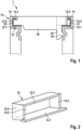
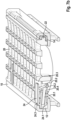
- FIG.1 a cross-sectional view of a gutter system 1 according to a first embodiment is shown.
- the gutter system 1 has a frame unit 10 and a cover unit 20.
- the frame unit 10 is provided with undercut receiving areas 12 on both sides.
- the receiving areas 12 are formed by at least three side walls using a first, second and third side wall 12.1; 12.2; 12.3.
- a first damping element 14 is provided along the three side walls 12.1; 12.2; 12.3.
- the first damping element 14 can be a surface coating or an insert 16 (cf. Fig.2 ) should be provided.
- the lid or grate unit 20 has according to Fig.1 at least one engagement element 22, which is provided for engagement in an undercut receiving area 12 of the frame unit 10.
- the first damping element 14 is formed between the frame unit 10 and the cover unit 20.
- the cover unit 20 can be formed on one side or both sides with at least one engagement element 22. According to Fig.1 a one-sided design of the engagement element 22 on the cover unit 20 is provided. In this sense, the cover unit 20 can be designed asymmetrically.
- a force-fitting and/or form-fitting connection of the cover unit 20 to the frame unit 10 is provided.
- the frame unit 10 has first bracing elements 18, which can be designed as a V-shaped groove symmetrically along a longitudinal axis of the channel system 1. This enables a reciprocal or direction-independent arrangement of the cover unit 20 on the frame unit 10.
- the cover unit 20 has at least one securing element 24, in particular in the form of a snap hook with a V-shaped nose for engagement in one of the first tensioning elements 18.
- the at least one securing element 24 is provided on the side of the cover unit 20 opposite the engagement element 22. In this way, a detachable force-fitting and/or form-fitting connection between the cover unit 20 and the frame unit 10 can be expediently provided.
- a force-fitting and/or form-fitting connection between the frame unit 10 and the cover unit 20 can be brought about in the sense of an at least partially rotational movement of the cover unit 20.
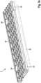
- Fig.2 is a perspective view of an insert 16 for use with a gutter system according to Fig.1 shown.
- the insert 16 can be introduced into one of the receiving areas 12 of the frame unit 10. In this sense, the insert 16 can provide dampened side walls 12.1; 12.2; 12.3; 12.4; 12.5 in different spatial directions, at least in three spatial directions, or serve as damping for intermediate ribs along the receiving area 12.
- any arrangement of several inserts 16 along the receiving area 12 is possible, in particular depending on the positioning of the securing elements 24 along the cover or grate unit 20.
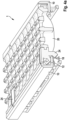
- Fig. 3a the cover unit with two securing elements 24 and two first damping elements 14, which are each spaced apart from one another in the longitudinal direction of the gutter system 1.
- the first damping elements 14 are therefore provided for section-wise damping of the cover unit 20 along the receiving area 12.
- damping can be provided in the longitudinal direction of the channel system 1, opposite the fourth and fifth side walls 12.4; 12.5 of the receiving area 12, which can be divided by intermediate ribs or the like.
- the intermediate ribs can be understood as fourth and fifth side walls 12.4; 12.5.
- Such intermediate ribs can also be used to provide dampened protection of the cover unit 20 against slipping in the longitudinal direction of the channel system 1.
- Fig. 3b the positioning of the engagement element 22 in the at least partially undercut receiving area 12 of the channel unit 10 is shown. In this way, the cover unit 20 cannot be removed from the frame unit 10 in an exclusively vertical direction.
- the engagement element 22 and the receiving area 12 represent a detachable interlock.
- Fig. 3c a dampened mounting of the cover unit 20 or the engagement element 22 in the receiving area 12 of the frame unit 10 is shown.
- the engagement element 22 is encompassed by the first damping element 14 or the first damping element 14 is arranged on the engagement element 22.
- damping can be provided in particular with respect to the first, second and third side walls 12.1; 12.2; 12.3 of the receiving area 12 of the frame unit 10.
- Fig. 3d the damped mounting of the engagement element 22 in the receiving area 12 divided by intermediate ribs is shown.
- the first damping element 14 surrounds the engagement element 22 of the cover unit 20 in such a way that a displacement lock in the longitudinal direction of the gutter system 1 is provided in a dampened form.
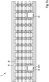
- FIG. 4a-b various views of a third embodiment of the gutter system 1 are shown.
- the securing element 24 engages in a force-fitting and/or form-fitting manner in the undercut receiving area 12 of the frame unit 10. Furthermore, the securing element 24 engages with a V-shaped nose in the first bracing element 18, which is provided below the receiving area for bracing the securing element 24 in combination with the cover or grate unit 20. In this way, an interlocking of the cover unit 20 on the frame unit 10 can be provided.
- the at least one first bracing element 18 can be arranged below the receiving area 12 on the frame unit 10 and cast or encapsulated.
- the frame unit 10 with the receiving areas 12 on both sides can be designed symmetrically, so that the cover unit 20 with the engagement elements 22 and the securing elements 24 can be inserted on both sides or alternately or independently of direction.
- a cross section of a fourth embodiment of the gutter system 1 is shown, in particular a representation of the securing element 24.
- a representation of the securing element 24 in particular a representation of the securing element 24.
- Various further views of the fourth embodiment are illustrated.
- the securing element 24 is designed as a rotationally movable securing element 24.
- the securing element 24 is accommodated in a receiving opening 20.3 of the cover unit 20 so as to be rotatably movable or is clipped onto a rotation shaft of the cover unit 20.
- the rotation axis of the securing element 24 is aligned on the cover unit 20 in the longitudinal direction of the channel system 1 and is provided directly adjacent to the receiving area 12 on the cover unit 20. In this way, the securing element 24 can engage or rotate into the undercut receiving area 12 of the frame unit 12 during a locking rotation.
- the locking lug of the securing element 24 can engage with a first bracing element 18 for locking or interlocking, which is formed on the cover or grate unit 20 in the form of a projection.
- the securing element 24 can be locked in a blocking position or locking position on the bracing element 18, wherein the securing element 24 engages in the undercut receiving area 12 on the opposite side of the rotation axis.
- the cover unit or the grate unit 20 and the frame unit 10 are connected by means of the securing element 24 in accordance with Fig.5 and 6 can be conveniently interlocked with one another.
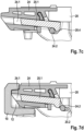
- Fig. 7a-d show various views of a fifth embodiment of the gutter system 1, in particular a representation of the securing element 24.
- the release area 24.3 is formed centrally in the transverse direction of the securing element 24.
- the securing element 24 can be designed such that it only partially closes the receiving opening 20.3.
- Several securing elements 24 are provided spaced apart from one another in the longitudinal direction of the gutter system 1.
- Fig. 7b a cross-sectional view of the fifth embodiment is shown.
- the frame unit 10 is designed with the receiving area 12 for storing and receiving the cover unit 20.
- the receiving area 12 is at least partially designed as an undercut or undercut.
- the cover unit 20 has a receiving opening 20.3 for storing and receiving the securing element 24.
- the receiving opening 20.3 can enlarge at least in sections from top to bottom, along the orientation of the cover unit 20 in normal use. In this way, waste or dirt that can enter the receiving opening 20.3 from above can fall through the cover or grate unit 20.
- the receiving opening 20.3 is formed with a support surface 20.2 in a central region of the cover unit 20 or the channel system 1.
- the support surface 20.2 runs essentially in a vertical direction and has a radius or a rounding at least at its lower end.
- the frame unit 20 has at least one bearing element 20.1.
- the bearing element 20.1 extends according to Fig.1 longitudinally and transversely to the longitudinal direction of the gutter system 1.
- the bearing element 20.1 can be designed to be slightly inclined relative to the horizontal.
- the bearing element 20.1 can have a loss prevention device 20.4 at one end, in particular in the direction of the central region of the channel system 1.
- the loss prevention device 20.4 can be designed as a bead or bulge along the bearing element 20.1. This provides a force-fitting and/or form-fitting connection between the cover unit 20 and the securing element 24. Captive interlocking is provided.
- the securing element 24 is in accordance with Fig.1 inserted into the lid or grate unit 20 and engages with a first end in a force-fitting and/or form-fitting manner in the receiving area 12 of the frame unit 10. Since the securing element 24 is designed with a bevel along its underside at this first end, the securing element 24 can be snapped into the receiving area 12 of the frame unit 10 in a simplified manner.
- the securing element 24 is designed with at least one bearing groove 24.1, which is designed to correspond to the bearing element 20.1 of the receiving opening 20.3 of the cover unit 20.
- the bearing element 20.1 can thus engage in the bearing groove 24.1 in a force-fitting and/or form-fitting manner for sliding reception.
- the securing element 24 can be supported and guided by the cover unit 20.
- the securing element 24 has a locking lever 24.2 at a second end, which is arranged in the middle area of the gutter system 1.
- the locking lever 24.2 is elastically and/or plastically deformable.
- the locking lever 24.2 is provided in such a way that it can be supported against the support surface 20.2 of the cover unit 20 in order to apply a closing force to the securing element 24 and thus ensure that it snaps into place or engages in the receiving opening 12 of the frame unit 10.
- the securing element 24 can be regarded as a spring-loaded securing element 24 with regard to the preferably elastically deformable locking lever 24.2.
- the securing element 30 has the release area 24.3, which is intended for engagement with, for example, a screwdriver, a lever element or the like.
- a release force can be applied to the securing element 24 using only an aid, which exceeds the closing force of the locking lever 24, supported on the support surface 20.2, in order to thus release the engagement of the securing element 24 in the receiving area 12 of the frame unit 10.
- FIG. 7c-d Cross-sectional views of the sixth embodiment are shown, in particular to illustrate the functionality of the securing element 24.
- the Fig. 7c and 7d the attachment or interlocking of the securing element 24 to the cover unit 20 so that a captive connection is ensured.
- the securing element 24 is inserted along the bearing grooves 24.1 and the bearing elements 20.1 into the cover unit 20 or into the receiving opening 20.3 of the cover unit 20.
- the locking lever 24.2 slides according to Fig. 7c also along the bearing element 20.1.
- the locking lever 24.2 can be elastically deformed and slide off the loss prevention device 20.4 of the bearing element 20.1 in such a way that the locking lever 24.2 can snap over and the locking lever 24.2 slides over the loss prevention device 20.4, in the form of a bead or bulge of the bearing element 20.1.
- the securing element 24 can be locked onto the cover unit 20.
- a captive connection or interlock between the cover unit 20 and the securing element 24 can be provided.
- the top of the securing element 24 can be designed in such a way that the sliding connection between the bearing elements 20.1 and the bearing grooves 24.1 is protected from contamination.
- the present invention allows the provision of a gutter system 1 with a simplified and cost-effective structure, whereby a safe and quiet reception of the cover or grate unit 20 along the frame unit 10 is ensured.
- a dampened and secured or theft-proof reception of the cover unit 20 on the frame unit 10 can be achieved.
Landscapes
- Health & Medical Sciences (AREA)
- Life Sciences & Earth Sciences (AREA)
- Engineering & Computer Science (AREA)
- Hydrology & Water Resources (AREA)
- Public Health (AREA)
- Water Supply & Treatment (AREA)
- Sewage (AREA)
Applications Claiming Priority (2)
| Application Number | Priority Date | Filing Date | Title |
|---|---|---|---|
| DE102019132117.4A DE102019132117A1 (de) | 2019-11-27 | 2019-11-27 | Rinnensystem |
| PCT/EP2020/083161 WO2021105098A1 (de) | 2019-11-27 | 2020-11-24 | Rinnensystem |
Publications (3)
| Publication Number | Publication Date |
|---|---|
| EP4065787A1 EP4065787A1 (de) | 2022-10-05 |
| EP4065787B1 true EP4065787B1 (de) | 2024-08-21 |
| EP4065787C0 EP4065787C0 (de) | 2024-08-21 |
Family
ID=73598081
Family Applications (1)
| Application Number | Title | Priority Date | Filing Date |
|---|---|---|---|
| EP20812267.1A Active EP4065787B1 (de) | 2019-11-27 | 2020-11-24 | Rinnensystem |
Country Status (7)
| Country | Link |
|---|---|
| US (1) | US12049750B2 (pl) |
| EP (1) | EP4065787B1 (pl) |
| CN (1) | CN114761646B (pl) |
| AU (1) | AU2020393377B2 (pl) |
| DE (1) | DE102019132117A1 (pl) |
| PL (1) | PL4065787T3 (pl) |
| WO (1) | WO2021105098A1 (pl) |
Families Citing this family (3)
| Publication number | Priority date | Publication date | Assignee | Title |
|---|---|---|---|---|
| DE102022116732A1 (de) * | 2022-07-05 | 2024-01-11 | Aco Ahlmann Se & Co. Kg | Längsstabrosteinheit |
| US12534899B2 (en) * | 2022-12-09 | 2026-01-27 | Midwest Design Group | Trench drains with suspended grates |
| US12546102B2 (en) * | 2023-02-23 | 2026-02-10 | Advanced Drainage Systems, Inc. | Linear or trench drain systems |
Family Cites Families (17)
| Publication number | Priority date | Publication date | Assignee | Title |
|---|---|---|---|---|
| DE7211578U (de) * | 1972-06-22 | Buderussche Eisenwerke | Klapperfreier Rost | |
| DE10112840C1 (de) * | 2001-03-16 | 2003-02-13 | Ahlmann Aco Severin | Entwässerungseinrichtung zur Oberflächenentwässerung |
| US7293937B2 (en) * | 2003-03-25 | 2007-11-13 | Aco Severin Ahlmann Gmbh & Co. Kg | Cover arrangement |
| DE10346586B4 (de) * | 2003-10-07 | 2006-06-01 | Aco Severin Ahlmann Gmbh & Co. Kg | Befestigungsvorrichtung |
| DE202005010323U1 (de) * | 2005-07-01 | 2005-09-15 | Heinrich Meier Eisengieserei G | Schachtabdeckung mit dämpfender Einlage |
| DE102009019375B4 (de) * | 2008-04-30 | 2023-08-10 | Aco Ahlmann Se & Co. Kg | Entwässerungsrinne mit Dämpfungselement |
| KR20110002525A (ko) * | 2009-07-02 | 2011-01-10 | 강오건설 주식회사 | 배수트렌치용 무소음 자립형 그레이팅 |
| DE202010000132U1 (de) * | 2010-02-05 | 2010-05-20 | Hauraton Gmbh & Co. Kg | Zarge mit Dämpfungselement |
| DE202010017019U1 (de) * | 2010-12-28 | 2012-03-29 | Hydrotec Technologies Ag | Entwässerungsvorrichtung |
| DE102012110941A1 (de) * | 2012-11-14 | 2014-05-15 | ACO Severin Ahlmann GmbH & Co Kommanditgesellschaft | Verschluss zum Verriegeln einer Abdeckung |
| CH708641B1 (de) * | 2013-09-22 | 2018-06-15 | Tschupp Roland | Einlaufrost für die Strassenentwässerung. |
| RU163464U1 (ru) | 2015-02-10 | 2016-07-20 | Василий Анатольевич Дубина | Элемент поверхностного водоотводного канала |
| DE102016108354A1 (de) * | 2016-05-04 | 2017-11-09 | ACO Severin Ahlmann GmbH & Co Kommanditgesellschaft | Stirnwand einer Rinne zur Oberflächenentwässerung |
| KR101889088B1 (ko) * | 2016-10-12 | 2018-08-16 | (주)태흥그레이팅 | 소음방지 그레이팅 |
| DE102016012437A1 (de) * | 2016-10-18 | 2018-04-19 | A.RAYMOND et Cie. SCS | Befestiger zum Sichern eines Halteelements an einem Träger und System umfassend einen Befestiger und ein Halteelement |
| DE102017105011A1 (de) * | 2017-03-09 | 2018-09-13 | ACO Severin Ahlmann GmbH & Co Kommanditgesellschaft | Rigolenkörper und Mittelplatte |
| CN109084328B (zh) | 2018-07-25 | 2020-08-04 | 湖南云顶智能科技有限公司 | 一种滑移弧放电增强超声速气雾掺混燃烧器 |
-
2019
- 2019-11-27 DE DE102019132117.4A patent/DE102019132117A1/de active Pending
-
2020
- 2020-11-24 EP EP20812267.1A patent/EP4065787B1/de active Active
- 2020-11-24 PL PL20812267.1T patent/PL4065787T3/pl unknown
- 2020-11-24 WO PCT/EP2020/083161 patent/WO2021105098A1/de not_active Ceased
- 2020-11-24 AU AU2020393377A patent/AU2020393377B2/en active Active
- 2020-11-24 CN CN202080081739.3A patent/CN114761646B/zh active Active
- 2020-11-24 US US17/756,381 patent/US12049750B2/en active Active
Also Published As
| Publication number | Publication date |
|---|---|
| US12049750B2 (en) | 2024-07-30 |
| US20220389703A1 (en) | 2022-12-08 |
| EP4065787C0 (de) | 2024-08-21 |
| AU2020393377A1 (en) | 2022-05-19 |
| WO2021105098A1 (de) | 2021-06-03 |
| AU2020393377B2 (en) | 2025-12-04 |
| PL4065787T3 (pl) | 2025-01-07 |
| CN114761646B (zh) | 2025-06-13 |
| CN114761646A (zh) | 2022-07-15 |
| DE102019132117A1 (de) | 2021-05-27 |
| EP4065787A1 (de) | 2022-10-05 |
Similar Documents
| Publication | Publication Date | Title |
|---|---|---|
| EP4065787B1 (de) | Rinnensystem | |
| WO2014166720A1 (de) | Halterung für einen führungsschuh eines klettersystems für betonschalungen | |
| EP3722527A1 (de) | Befestigungsvorrichtung zur befestigung von fassadenelementen einer elementfassade | |
| EP1899553A1 (de) | Deckenschalungssystem | |
| EP1855913A2 (de) | Feststellvorrichtung für einen einstellbaren fahrzeugsitz | |
| EP3623537B1 (de) | Höhenverstellbare entwässerungsrinne | |
| EP4065788A1 (de) | Rinnensystem, deckeleinheit und sicherungselement | |
| EP0687784B1 (de) | Hochbauentwässerungsrinne | |
| DE3904026C2 (pl) | ||
| EP2543548B1 (de) | Befestigungssystem für einen Kraftfahrzeugdachträger | |
| WO2018082728A1 (de) | Sammelschienenhalter und eine entsprechende anordnung | |
| DE29511547U1 (de) | Vorrichtung zur axial unverschieblichen, lösbaren Befestigung einer Handhabe an einem Lagerteil, insbesondere für Türdrücker, Fenstergriffe o.dgl. | |
| EP1597441B1 (de) | Entw sserungsvorrichtung | |
| DE69804739T2 (de) | Vorrichtung zur Befestigung einer Vorderfront an einem Vorderbau eines Kraftfahrzeuges | |
| DE19921810B4 (de) | Rastbeschlag für einen Fahrzeugsitz | |
| EP2578759B1 (de) | Verriegelungsmechanismus für Ablauf | |
| EP0566829B1 (de) | Abfangkonsole für Mauersteine, Verblendplatten o. dgl. | |
| EP0758038B1 (de) | Entwässerungsrinne | |
| DE20020753U1 (de) | Verankerungseinrichtung für einen werkzeuglos ein- und ausbaubaren Fahrzeugsitz | |
| DE3536623A1 (de) | Einbaudose fuer elektrische installationsgeraete | |
| DE102018112026A1 (de) | Führungsvorrichtung für eine Schiebetür und Verfahren zur Montage einer Führungsschiene | |
| DE102022125081B3 (de) | Bodenstütze eines Kabeltragsystems | |
| EP0537552B1 (de) | Vorrichtung zur Verriegelung eines Abdeckrostes an einem Rahmen | |
| EP4108849B1 (de) | Profilsystem zur bildung einer terrassenbodenunterkonstruktion | |
| EP1507049B1 (de) | Entwässerungsrinne |
Legal Events
| Date | Code | Title | Description |
|---|---|---|---|
| STAA | Information on the status of an ep patent application or granted ep patent |
Free format text: STATUS: UNKNOWN |
|
| STAA | Information on the status of an ep patent application or granted ep patent |
Free format text: STATUS: THE INTERNATIONAL PUBLICATION HAS BEEN MADE |
|
| PUAI | Public reference made under article 153(3) epc to a published international application that has entered the european phase |
Free format text: ORIGINAL CODE: 0009012 |
|
| STAA | Information on the status of an ep patent application or granted ep patent |
Free format text: STATUS: REQUEST FOR EXAMINATION WAS MADE |
|
| 17P | Request for examination filed |
Effective date: 20220623 |
|
| AK | Designated contracting states |
Kind code of ref document: A1 Designated state(s): AL AT BE BG CH CY CZ DE DK EE ES FI FR GB GR HR HU IE IS IT LI LT LU LV MC MK MT NL NO PL PT RO RS SE SI SK SM TR |
|
| DAV | Request for validation of the european patent (deleted) | ||
| DAX | Request for extension of the european patent (deleted) | ||
| GRAP | Despatch of communication of intention to grant a patent |
Free format text: ORIGINAL CODE: EPIDOSNIGR1 |
|
| STAA | Information on the status of an ep patent application or granted ep patent |
Free format text: STATUS: GRANT OF PATENT IS INTENDED |
|
| INTG | Intention to grant announced |
Effective date: 20240402 |
|
| GRAS | Grant fee paid |
Free format text: ORIGINAL CODE: EPIDOSNIGR3 |
|
| GRAA | (expected) grant |
Free format text: ORIGINAL CODE: 0009210 |
|
| STAA | Information on the status of an ep patent application or granted ep patent |
Free format text: STATUS: THE PATENT HAS BEEN GRANTED |
|
| AK | Designated contracting states |
Kind code of ref document: B1 Designated state(s): AL AT BE BG CH CY CZ DE DK EE ES FI FR GB GR HR HU IE IS IT LI LT LU LV MC MK MT NL NO PL PT RO RS SE SI SK SM TR |
|
| REG | Reference to a national code |
Ref country code: GB Ref legal event code: FG4D Free format text: NOT ENGLISH |
|
| REG | Reference to a national code |
Ref country code: CH Ref legal event code: EP |
|
| REG | Reference to a national code |
Ref country code: DE Ref legal event code: R096 Ref document number: 502020008971 Country of ref document: DE |
|
| REG | Reference to a national code |
Ref country code: IE Ref legal event code: FG4D Free format text: LANGUAGE OF EP DOCUMENT: GERMAN |
|
| U01 | Request for unitary effect filed |
Effective date: 20240910 |
|
| U07 | Unitary effect registered |
Designated state(s): AT BE BG DE DK EE FI FR IT LT LU LV MT NL PT RO SE SI Effective date: 20240930 |
|
| U20 | Renewal fee for the european patent with unitary effect paid |
Year of fee payment: 5 Effective date: 20241125 |
|
| PG25 | Lapsed in a contracting state [announced via postgrant information from national office to epo] |
Ref country code: GR Free format text: LAPSE BECAUSE OF FAILURE TO SUBMIT A TRANSLATION OF THE DESCRIPTION OR TO PAY THE FEE WITHIN THE PRESCRIBED TIME-LIMIT Effective date: 20241122 |
|
| PG25 | Lapsed in a contracting state [announced via postgrant information from national office to epo] |
Ref country code: IS Free format text: LAPSE BECAUSE OF FAILURE TO SUBMIT A TRANSLATION OF THE DESCRIPTION OR TO PAY THE FEE WITHIN THE PRESCRIBED TIME-LIMIT Effective date: 20241221 |
|
| PG25 | Lapsed in a contracting state [announced via postgrant information from national office to epo] |
Ref country code: HR Free format text: LAPSE BECAUSE OF FAILURE TO SUBMIT A TRANSLATION OF THE DESCRIPTION OR TO PAY THE FEE WITHIN THE PRESCRIBED TIME-LIMIT Effective date: 20240821 |
|
| PG25 | Lapsed in a contracting state [announced via postgrant information from national office to epo] |
Ref country code: RS Free format text: LAPSE BECAUSE OF FAILURE TO SUBMIT A TRANSLATION OF THE DESCRIPTION OR TO PAY THE FEE WITHIN THE PRESCRIBED TIME-LIMIT Effective date: 20241121 Ref country code: ES Free format text: LAPSE BECAUSE OF FAILURE TO SUBMIT A TRANSLATION OF THE DESCRIPTION OR TO PAY THE FEE WITHIN THE PRESCRIBED TIME-LIMIT Effective date: 20240821 |
|
| PG25 | Lapsed in a contracting state [announced via postgrant information from national office to epo] |
Ref country code: RS Free format text: LAPSE BECAUSE OF FAILURE TO SUBMIT A TRANSLATION OF THE DESCRIPTION OR TO PAY THE FEE WITHIN THE PRESCRIBED TIME-LIMIT Effective date: 20241121 Ref country code: IS Free format text: LAPSE BECAUSE OF FAILURE TO SUBMIT A TRANSLATION OF THE DESCRIPTION OR TO PAY THE FEE WITHIN THE PRESCRIBED TIME-LIMIT Effective date: 20241221 Ref country code: HR Free format text: LAPSE BECAUSE OF FAILURE TO SUBMIT A TRANSLATION OF THE DESCRIPTION OR TO PAY THE FEE WITHIN THE PRESCRIBED TIME-LIMIT Effective date: 20240821 Ref country code: GR Free format text: LAPSE BECAUSE OF FAILURE TO SUBMIT A TRANSLATION OF THE DESCRIPTION OR TO PAY THE FEE WITHIN THE PRESCRIBED TIME-LIMIT Effective date: 20241122 Ref country code: ES Free format text: LAPSE BECAUSE OF FAILURE TO SUBMIT A TRANSLATION OF THE DESCRIPTION OR TO PAY THE FEE WITHIN THE PRESCRIBED TIME-LIMIT Effective date: 20240821 |
|
| PG25 | Lapsed in a contracting state [announced via postgrant information from national office to epo] |
Ref country code: SM Free format text: LAPSE BECAUSE OF FAILURE TO SUBMIT A TRANSLATION OF THE DESCRIPTION OR TO PAY THE FEE WITHIN THE PRESCRIBED TIME-LIMIT Effective date: 20240821 |
|
| PG25 | Lapsed in a contracting state [announced via postgrant information from national office to epo] |
Ref country code: SK Free format text: LAPSE BECAUSE OF FAILURE TO SUBMIT A TRANSLATION OF THE DESCRIPTION OR TO PAY THE FEE WITHIN THE PRESCRIBED TIME-LIMIT Effective date: 20240821 |
|
| PLBE | No opposition filed within time limit |
Free format text: ORIGINAL CODE: 0009261 |
|
| STAA | Information on the status of an ep patent application or granted ep patent |
Free format text: STATUS: NO OPPOSITION FILED WITHIN TIME LIMIT |
|
| REG | Reference to a national code |
Ref country code: CH Ref legal event code: PL |
|
| PG25 | Lapsed in a contracting state [announced via postgrant information from national office to epo] |
Ref country code: MC Free format text: LAPSE BECAUSE OF FAILURE TO SUBMIT A TRANSLATION OF THE DESCRIPTION OR TO PAY THE FEE WITHIN THE PRESCRIBED TIME-LIMIT Effective date: 20240821 |
|
| REG | Reference to a national code |
Ref country code: CH Ref legal event code: PL |
|
| PG25 | Lapsed in a contracting state [announced via postgrant information from national office to epo] |
Ref country code: CH Free format text: LAPSE BECAUSE OF NON-PAYMENT OF DUE FEES Effective date: 20241130 |
|
| 26N | No opposition filed |
Effective date: 20250522 |
|
| PG25 | Lapsed in a contracting state [announced via postgrant information from national office to epo] |
Ref country code: IE Free format text: LAPSE BECAUSE OF NON-PAYMENT OF DUE FEES Effective date: 20241124 |
|
| U20 | Renewal fee for the european patent with unitary effect paid |
Year of fee payment: 6 Effective date: 20251117 |
|
| PGFP | Annual fee paid to national office [announced via postgrant information from national office to epo] |
Ref country code: GB Payment date: 20251120 Year of fee payment: 6 |
|
| PGFP | Annual fee paid to national office [announced via postgrant information from national office to epo] |
Ref country code: NO Payment date: 20251118 Year of fee payment: 6 |
|
| PGFP | Annual fee paid to national office [announced via postgrant information from national office to epo] |
Ref country code: CZ Payment date: 20251111 Year of fee payment: 6 |
|
| PGFP | Annual fee paid to national office [announced via postgrant information from national office to epo] |
Ref country code: PL Payment date: 20251113 Year of fee payment: 6 |
|
| PG25 | Lapsed in a contracting state [announced via postgrant information from national office to epo] |
Ref country code: HU Free format text: LAPSE BECAUSE OF FAILURE TO SUBMIT A TRANSLATION OF THE DESCRIPTION OR TO PAY THE FEE WITHIN THE PRESCRIBED TIME-LIMIT; INVALID AB INITIO Effective date: 20201124 |
|
| PG25 | Lapsed in a contracting state [announced via postgrant information from national office to epo] |
Ref country code: CY Free format text: LAPSE BECAUSE OF FAILURE TO SUBMIT A TRANSLATION OF THE DESCRIPTION OR TO PAY THE FEE WITHIN THE PRESCRIBED TIME-LIMIT; INVALID AB INITIO Effective date: 20201124 |