EP4064442B1 - Verfahren zur herstellung einer in einen separator integrierten elektrode mit anorganischen schichten mit mehrschichtstruktur und damit hergestellte separatorintegrierte elektrode - Google Patents
Verfahren zur herstellung einer in einen separator integrierten elektrode mit anorganischen schichten mit mehrschichtstruktur und damit hergestellte separatorintegrierte elektrode Download PDFInfo
- Publication number
- EP4064442B1 EP4064442B1 EP21747560.7A EP21747560A EP4064442B1 EP 4064442 B1 EP4064442 B1 EP 4064442B1 EP 21747560 A EP21747560 A EP 21747560A EP 4064442 B1 EP4064442 B1 EP 4064442B1
- Authority
- EP
- European Patent Office
- Prior art keywords
- inorganic
- inorganic layer
- electrode
- particles
- layer
- Prior art date
- Legal status (The legal status is an assumption and is not a legal conclusion. Google has not performed a legal analysis and makes no representation as to the accuracy of the status listed.)
- Active
Links
Images


Classifications
-
- H—ELECTRICITY
- H01—ELECTRIC ELEMENTS
- H01M—PROCESSES OR MEANS, e.g. BATTERIES, FOR THE DIRECT CONVERSION OF CHEMICAL ENERGY INTO ELECTRICAL ENERGY
- H01M50/00—Constructional details or processes of manufacture of the non-active parts of electrochemical cells other than fuel cells, e.g. hybrid cells
- H01M50/40—Separators; Membranes; Diaphragms; Spacing elements inside cells
- H01M50/409—Separators, membranes or diaphragms characterised by the material
- H01M50/443—Particulate material
-
- H—ELECTRICITY
- H01—ELECTRIC ELEMENTS
- H01M—PROCESSES OR MEANS, e.g. BATTERIES, FOR THE DIRECT CONVERSION OF CHEMICAL ENERGY INTO ELECTRICAL ENERGY
- H01M4/00—Electrodes
- H01M4/02—Electrodes composed of, or comprising, active material
- H01M4/13—Electrodes for accumulators with non-aqueous electrolyte, e.g. for lithium-accumulators; Processes of manufacture thereof
- H01M4/139—Processes of manufacture
-
- H—ELECTRICITY
- H01—ELECTRIC ELEMENTS
- H01M—PROCESSES OR MEANS, e.g. BATTERIES, FOR THE DIRECT CONVERSION OF CHEMICAL ENERGY INTO ELECTRICAL ENERGY
- H01M50/00—Constructional details or processes of manufacture of the non-active parts of electrochemical cells other than fuel cells, e.g. hybrid cells
- H01M50/40—Separators; Membranes; Diaphragms; Spacing elements inside cells
- H01M50/403—Manufacturing processes of separators, membranes or diaphragms
-
- H—ELECTRICITY
- H01—ELECTRIC ELEMENTS
- H01M—PROCESSES OR MEANS, e.g. BATTERIES, FOR THE DIRECT CONVERSION OF CHEMICAL ENERGY INTO ELECTRICAL ENERGY
- H01M50/00—Constructional details or processes of manufacture of the non-active parts of electrochemical cells other than fuel cells, e.g. hybrid cells
- H01M50/40—Separators; Membranes; Diaphragms; Spacing elements inside cells
- H01M50/409—Separators, membranes or diaphragms characterised by the material
- H01M50/431—Inorganic material
- H01M50/434—Ceramics
-
- H—ELECTRICITY
- H01—ELECTRIC ELEMENTS
- H01M—PROCESSES OR MEANS, e.g. BATTERIES, FOR THE DIRECT CONVERSION OF CHEMICAL ENERGY INTO ELECTRICAL ENERGY
- H01M50/00—Constructional details or processes of manufacture of the non-active parts of electrochemical cells other than fuel cells, e.g. hybrid cells
- H01M50/40—Separators; Membranes; Diaphragms; Spacing elements inside cells
- H01M50/409—Separators, membranes or diaphragms characterised by the material
- H01M50/446—Composite material consisting of a mixture of organic and inorganic materials
-
- H—ELECTRICITY
- H01—ELECTRIC ELEMENTS
- H01M—PROCESSES OR MEANS, e.g. BATTERIES, FOR THE DIRECT CONVERSION OF CHEMICAL ENERGY INTO ELECTRICAL ENERGY
- H01M50/00—Constructional details or processes of manufacture of the non-active parts of electrochemical cells other than fuel cells, e.g. hybrid cells
- H01M50/40—Separators; Membranes; Diaphragms; Spacing elements inside cells
- H01M50/409—Separators, membranes or diaphragms characterised by the material
- H01M50/449—Separators, membranes or diaphragms characterised by the material having a layered structure
-
- H—ELECTRICITY
- H01—ELECTRIC ELEMENTS
- H01M—PROCESSES OR MEANS, e.g. BATTERIES, FOR THE DIRECT CONVERSION OF CHEMICAL ENERGY INTO ELECTRICAL ENERGY
- H01M50/00—Constructional details or processes of manufacture of the non-active parts of electrochemical cells other than fuel cells, e.g. hybrid cells
- H01M50/40—Separators; Membranes; Diaphragms; Spacing elements inside cells
- H01M50/46—Separators, membranes or diaphragms characterised by their combination with electrodes
-
- H—ELECTRICITY
- H01—ELECTRIC ELEMENTS
- H01M—PROCESSES OR MEANS, e.g. BATTERIES, FOR THE DIRECT CONVERSION OF CHEMICAL ENERGY INTO ELECTRICAL ENERGY
- H01M4/00—Electrodes
- H01M4/02—Electrodes composed of, or comprising, active material
- H01M2004/021—Physical characteristics, e.g. porosity, surface area
-
- Y—GENERAL TAGGING OF NEW TECHNOLOGICAL DEVELOPMENTS; GENERAL TAGGING OF CROSS-SECTIONAL TECHNOLOGIES SPANNING OVER SEVERAL SECTIONS OF THE IPC; TECHNICAL SUBJECTS COVERED BY FORMER USPC CROSS-REFERENCE ART COLLECTIONS [XRACs] AND DIGESTS
- Y02—TECHNOLOGIES OR APPLICATIONS FOR MITIGATION OR ADAPTATION AGAINST CLIMATE CHANGE
- Y02E—REDUCTION OF GREENHOUSE GAS [GHG] EMISSIONS, RELATED TO ENERGY GENERATION, TRANSMISSION OR DISTRIBUTION
- Y02E60/00—Enabling technologies; Technologies with a potential or indirect contribution to GHG emissions mitigation
- Y02E60/10—Energy storage using batteries
Definitions
- the present invention relates to a method of manufacturing a separator-composite electrode as defined in method claims 1 to 12.
- the invention according to claim 13 refers to a separator-composite electrode manufactured by the method according to claims 1 to 12.
- the invention according to claim 14 refers to an electrode assembly comprising the electrode according to claim 13.
- a separator which is an element constituting a secondary battery, serves to pass an electrolyte and ions. while isolating a positive electrode and a negative electrode from each other to prevent electric short circuit between the two electrodes.
- the separator itself does not participate in electrochemical reaction of a secondary battery.
- the separator greatly affects the performance and safety of the secondary battery due to physical properties thereof, such as electrolytic solution wettability, porosity, and thermal shrinkage.
- a polyolefin-based porous substrate is widely used as a separator for a secondary battery. Since the porous substrate is subject to thermal shrinkage at high temperatures, it does not properly perform its role of isolating the positive electrode and the negative electrode. As a result, safety issues such as short-circuiting of secondary batteries or fire breakout or explosion of batteries have been raised.
- a method of adding a coating layer to one surface or both surfaces of the porous substrate and adding various kinds of materials capable of supplementing the disadvantages of the porous substrate to the coating layer or changing the physical properties of the coating layer has been used.
- Metal oxide such as alumina (Al 2 O 3 ), or metal hydroxide, such as aluminum hydroxide (Al(OH) 3 ), is added to the coating layer as an inorganic material to inhibit thermal shrinkage of the separator or improve heat resistance.
- a separator-composite electrode in which an inorganic coating layer is formed on an electrode active material layer to serve as a conventional separator has been proposed. Since an electrode assembly using the separator-composite electrode does not have a separate porous substrate, there is no concern for thermal shrinkage and hence short circuit. There is also an advantage in that it is possible to minimize the portion of the secondary battery that does not participate in the chemical reaction.
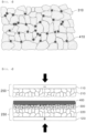
- the diameter of particles of the inorganic layer 30 of the conventional separator-composite electrode is smaller than pores of the electrode active material layer 20 formed on the electrode.
- the particles of the inorganic layer 30 may block the pores of the electrode active material layer 20 to increase the resistance of the battery.
- a binder for adhering the inorganic layer may block the pores of the electrode active material layer 20 formed on the electrode.
- Patent Document 2 also relates to an electrode provided with a current collector, an active material layer, and an inorganic layer.
- Patent Document 2 uses ceramic fillers of various sizes and shapes to increase ionic conductivity of a ceramic separator itself by providing the inorganic layer having a diameter of two or more kinds of particles. However, since this is to improve the performance of the separator itself, Patent Document 2 does not recognize that pores of a battery are blocked or the battery performance is deteriorated.
- KR 101 351 700 B1 ('Patent Document 3') refers to an electrode whose active material layer is coated with two ceramic particle layers.
- the particle size of the first layer coated directly on the electrode has a particle size which is larger than the second ceramic particle layer coated on the first layer.
- the present invention has been made in view of the above problems, and it is an object of the present invention to provide a method of manufacturing a separator-composite electrode having low resistance as well as no deterioration of battery performance by not blocking pores of an electrode active material layer, wherein the separator-composite electrode is provided with a multilayer-structured inorganic layer serving as a separator attached to one surface of an electrode without a separate separator. Since the present invention has no separate separator and the multilayer-structured inorganic layer serving as a separator does not include a polymer substrate, it is also an object of the present invention to provide the separator-composite electrode having excellent safety even at high temperatures.
- 1 cP corresponds to 0.001 Pa.s.
- the present invention provides a method of manufacturing a separator-composite electrode including S1) manufacturing a first inorganic layer slurry comprising first inorganic particles and a first binder and having a viscosity of 5000 cP to 20000 cP; S2) manufacturing a second inorganic layer slurry comprising second inorganic particles and a second binder; S3) preparing a unit electrode comprising an electrode active material layer formed on at least one surface of an electrode current collector; and S4) forming a first inorganic layer comprising the first inorganic layer slurry on at least one surface of the electrode active material layer of the unit electrode of step S3) and a second inorganic layer comprising the second inorganic layer slurry on the first inorganic layer, wherein a D50 diameter of the first inorganic particles is greater than a pore size of the electrode active material layer of the unit electrode, and a D50 diameter of the second inorganic particles is smaller than the diameter of the first inorganic particles
- Step S2) may include mixing the second inorganic particles and a second solvent to manufacture a second inorganic material solution; manufacturing a second binder solution in which the second binder polymer and the second solvent are mixed; and mixing the second inorganic material solution and the second binder solution to manufacture the second inorganic layer slurry.
- the first inorganic particles may have a diameter of 500 nm to 3 ⁇ m, and the second inorganic particles may have a diameter of 20 nm to 300 nm.
- the first inorganic layer slurry in step S1) and/or the second inorganic layer slurry in step S2) may further comprise a dispersant.
- the type of the dispersant is not limited as long as it is a material that can be generally used for a battery.
- the dispersant may be a mixture of one or more selected from the group consisting of an acrylic copolymer.
- the dispersant may be a mixture of one or more selected from the group consisting of acids.
- the second inorganic particles may be mixed with particles having different diameters.
- the second inorganic particles may be manufactured by adding a step of sequentially mixing the particles in the order of small diameter of the particles in step S2).
- a step of mixing a dispersant may be further included between the step of mixing the particles having a small diameter and the step of mixing the particles having a large diameter.
- the first inorganic layer slurry may have a higher viscosity than the second inorganic layer slurry.
- the second inorganic layer slurry may have a viscosity of 300 cP to 3000 cP.
- step S4) the first inorganic layer slurry and the second inorganic layer slurry may be simultaneously coated on at least one surface of the electrode active material layer of the unit electrode.
- the first inorganic layer slurry may be applied to at least one surface of the electrode active material layer of the unit electrode and then dried to form the first inorganic layer, and the second inorganic layer slurry may be applied on the first inorganic layer and then dried to form the second inorganic layer.
- a step of laminating each of the first inorganic layer and/or the second inorganic layer, after forming the first inorganic layer and/or the second inorganic layer, may be further comprised.
- the laminating step may be performed at 50°C to 200°C.
- the first inorganic particles and/or the second inorganic particles may include at least one of AlOOH, Al(OH) 3 , or Al 2 O 3 .
- the second inorganic particles may include surface-modified particles.
- the first binder polymer and the second binder polymer may be the same material, and may differ only in molecular weight or composition ratio of a copolymer.
- the second binder polymer may have a different chemical composition from the first binder polymer.
- a molecular structure of the second binder polymer may be branched.
- the total thickness of the inorganic layer which is the sum of the thickness of the first inorganic layer and the thickness of the second inorganic layer, may be less than 30 ⁇ m. Preferably, the total thickness of the inorganic layer may be 20 ⁇ m or less.
- the first inorganic layer and the second inorganic layer may have the same thickness.
- the unit cell may be used by charging and discharging 20 or more times.
- one or more constructions that do not conflict with each other may be selected and combined from among the above constructions.
- a method of manufacturing a separator-composite electrode according to the present invention serves to form a first inorganic layer and a second inorganic layer having different diameters and properties of inorganic particles and different physical properties of a slurry forming an inorganic layer, to maintain existing pores of an electrode by the first inorganic layer, to uniformly form pores of the electrode by the second inorganic layer, and to prevent an electrical short circuit.
- the separator-composite electrode according to the present invention does not have a porous polymer substrate and uses an endothermic inorganic material, it has excellent safety even at high temperatures.
- an electrode active material layer of a unit electrode can maintain the existing pores by the first inorganic layer, it is possible to provide an electrode assembly having a lower resistance than a conventional separator-composite electrode. As the resistance of the electrode assembly decreases, capacity and lifespan of a battery are improved.
- the present invention also has an excellent effect of preventing an electrical short circuit compared to the conventional separator-composite electrode by controlling the pore size of the second inorganic layer.
- the present invention may have an effect of preventing an electrical short circuit to a degree similar to that of the conventional polymer porous substrate and improving durability of the second inorganic layer and the separator-composite electrode.
- the present invention since the present invention has no separator substrate, a method of manufacturing an electrode assembly of the present invention is simpler than a conventional method of manufacturing an electrode assembly having a separator substrate, thereby it is possible to simplify an electrode assembly manufacturing method and a lamination process.
- one part is said to be connected to another part in the entire specification, not only may the one part be directly connected to the other part, but also, the one part may be indirectly connected to the other part via a further part.
- a certain element is included does not mean that other elements are excluded, but means that such elements may be further included unless mentioned otherwise.
- a method of manufacturing a separator-composite electrode according to the present invention includes S1) manufacturing a first inorganic layer slurry comprising first inorganic particles and a first binder and having a viscosity of 5000 cP to 20000 cP; S2) manufacturing a second inorganic layer slurry comprising second inorganic particles and a second binder; S3) preparing a unit electrode in which an electrode active material layer is formed on at least one surface of an electrode current collector; and S4) forming a first inorganic layer comprising the first inorganic layer slurry on at least one surface of the electrode active material layer of the unit electrode of step S3) and a second inorganic layer comprising the second inorganic layer slurry on the first inorganic layer, wherein a diameter of the first inorganic particles is greater than a pore size of the electrode active material layer of the unit electrode, and a diameter of the second inorganic particles is smaller than the diameter of the first inorganic particles, and steps S1) to S3) may be
- the first inorganic layer slurry may use a method of mixing the first inorganic particles and the first binder in a first solvent at once.
- the first inorganic layer slurry may be manufactured by a method including mixing the first inorganic particles and a first solvent to manufacture a first inorganic material solution; manufacturing a first binder solution in which the first binder polymer and the first solvent are mixed; and mixing the first inorganic material solution and the first binder solution to manufacture the first inorganic layer slurry.
- the above-described method may also be applied when forming the second inorganic layer slurry.
- the separator-composite electrode may include a unit electrode 250 including an electrode current collector 100 having an electrode active material layer 200 formed on one surface of the electrode current collector 100; a first inorganic layer 300 formed on one surface of the unit electrode 250, the first inorganic layer 300 including first inorganic particles having a diameter greater than a pore size of the electrode active material layer 200 of the unit electrode 250 and a first binder polymer; and a second inorganic layer 400 applied to the first inorganic layer 300, the second inorganic layer 400 including second inorganic particles having a diameter smaller than that of the first inorganic particles and a second binder polymer.
- the unit electrode 250 includes the electrode current collector 100 and the electrode active material layer 200 formed on at least one surface of the electrode current collector 100.
- the electrode active material layer 200 is formed only on one surface as an example, but the electrode active material layer 200 may be formed on both surfaces.
- the electrode current collector 100 may have a thickness of 3 ⁇ m to 500 ⁇ m.
- the electrode current collector 100 may have a micro-scale uneven pattern formed on the surface thereof so as to increase the adhesion force of the electrode active material.
- the current collector may be used in various physical forms, such as those of a film, a sheet, a foil, a net, a porous body, a foam body, and a non-woven fabric body.
- the material used as the electrode current collector is not particularly restricted, as long as the electrode current collector exhibits high conductivity while the electrode current collector does not induce any chemical change in a battery to which the electrode current collector is applied.
- both a positive electrode current collector and a negative electrode current collector may be used as the electrode current collector of the present invention.
- the positive electrode current collector may be made of one selected from stainless steel, aluminum, nickel, and titanium. Alternatively, the positive electrode current collector may be made of one selected from aluminum or stainless steel, the surface of which is treated with carbon, nickel, titanium, or silver. Preferably, aluminum may be used.
- the negative electrode current collector may be made of copper, stainless steel, aluminum, nickel, titanium, or sintered carbon. Alternatively, the negative electrode current collector may be made of copper or stainless steel, the surface of which is treated with carbon, nickel, titanium, or silver, or an aluminum-cadmium alloy.
- the electrode active material layer 200 may be formed on one surface or both surfaces of the electrode current collector 100.
- the thickness of the electrode active material layer 200 may vary depending on the capacity of the battery and the type of the active material. In general, the electrode active material layer 200 formed on one surface of the electrode current collector 100 may have a thickness of 3 ⁇ m to 500 ⁇ m.
- a negative electrode active material that can be used may include, for example, carbon such as non-graphitized carbon and graphite-based carbon; a metal composite oxide, such as Li x Fe 2 O 3 (0 ⁇ x ⁇ 1), Li x WO 2 (0 ⁇ x ⁇ 1), Sn x Me 1-x Me' y O z (Me: Mn, Fe, Pb, Ge; Me': Al, B, P, Si, Group 1, 2 and 3 elements of the periodic table, halogen; 0 ⁇ x ⁇ 1; 1 ⁇ y ⁇ 3; 1 ⁇ z ⁇ 8); lithium metal; lithium alloy; silicon-based alloy; tin-based alloy; a metal oxide, such as SnO, SnO 2 , PbO, PbO 2 , Pb 2 O 3 , Pb 3 O 4 , Sb 2 O 3 , Sb 2 O 4 , Sb 2 O 5 , GeO, GeO 2 , Bi 2 O 3 , Bi 2 O 4 , and Bi 2 O 5 ;
- a metal composite oxide such
- the electrode active material layer 200 may further include a conductive material and a binder.
- the conductive agent is generally added so that the conductive agent accounts for 0.1 wt% to 30 wt% based on the total weight of the mixture including the electrode active material.
- the conductive agent is not particularly restricted, as long as the conductive agent exhibits high conductivity without inducing any chemical change in a battery to which the conductive agent is applied.
- graphite such as natural graphite or artificial graphite
- carbon black such as carbon black, acetylene black, Ketjen black, channel black, furnace black, lamp black, or thermal black
- conductive fiber such as carbon fiber or metallic fiber
- carbon fluoride powder metallic powder, such as aluminum powder, or nickel powder
- conductive whisker such as a zinc oxide or potassium titanate
- a conductive metal oxide such as a titanium oxide
- conductive substances such as polyphenylene derivatives, may be used as the conductive agent.
- the binder is a component assisting in binding between an active material and a conductive agent and in binding with a current collector.
- the binder is generally added in an amount of 0.1 wt% to 30 wt% based on the total weight of the mixture including the electrode active material.
- binder examples may be polyvinylidene fluoride, polyvinyl alcohol, carboxymethylcellulose (CMC), starch, hydroxypropylcellulose, regenerated cellulose, polyvinyl pyrrolidone, polytetrafluoroethylene, polyethylene, polypropylene, ethylene-propylene-non-conjugated diene (EPDM), sulfonated EPDM, styrene butadiene rubber, fluoro rubber, and various copolymers.
- CMC carboxymethylcellulose
- EPDM ethylene-propylene-non-conjugated diene
- EPDM ethylene-propylene-non-conjugated diene
- EPDM ethylene-propylene-non-conjugated diene
- styrene butadiene rubber fluoro rubber
- the electrode active material may have a uniform particle diameter and shape, but various particles having different sizes and shapes may be used.
- the particle of the electrode active material may have a diameter of 800 nm to 20 ⁇ m.
- the particles may have various shapes such as a spherical shape or a rod shape.
- the electrode current collectors 10 and 100 and the electrode active material layers 20 and 200 are equally applied to an electrode current collector and an electrode active material layer described below.
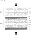
- a first inorganic layer 300 is disposed on at least one surface of the electrode active material layer 200 of the unit electrode 250, and a second inorganic layer 400 is always disposed on an upper surface of the first inorganic layer.
- the first inorganic layer 300 may include first inorganic particles having a diameter greater than the pore size of the electrode active material layer 200 of the unit electrode 250, and a first binder polymer for fixing the first inorganic particles.
- the second inorganic layer 400 may include second inorganic particles having a diameter smaller than that of the first inorganic particles, and a second binder polymer for fixing the second inorganic particles.
- the first inorganic layer 300 and the second inorganic layer 400 may exist as separate layers or may be formed as a single layer.
- the second inorganic particles 410 may be packed in pores of the first inorganic particles 310, as shown in FIG. 3 .
- the weight of the first inorganic particles 310 may be 50% to 90% based on the total weight of the inorganic particles
- the weight of the second inorganic particles 410 may be included 10% to 50% based on the total weight of the inorganic particles.
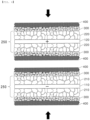
- the electrode assembly may be formed by stacking a separator-composite electrode including the first inorganic layer 300 and the second inorganic layer 400 on one surface as shown in FIG. 4 .
- the directions of the surfaces on which the first inorganic layer 300 and the second inorganic layer 400 are present may be formed to face one direction.
- active material layers 210 and 220 are shown to exist only on one surface of a negative electrode current collector 110 and a positive electrode current collector 120. However, the active material layers may exist on one surface as shown in FIG. 4 , or the active material layers may also exist on both surfaces.
- the unit electrode 250 includes both a unit electrode of a positive electrode and a unit electrode of a negative electrode.
- the electrode active material layers 20 and 200, the inorganic layer 30, the first inorganic layer 300, and the first inorganic particles 310, the second inorganic layer 400, and the second inorganic particles 410 also include both a positive electrode and a negative electrode.
- a unit electrode of a negative electrode in which a negative electrode active material layer including graphite is formed on one surface of a copper electrode current collector is prepared.
- Example 1-2 is formed in the same manner as in Example 1-1, but a unit cell is formed such that the first inorganic layer has a thickness of 10 ⁇ m and the second inorganic layer has a thickness of 10 ⁇ m.
- Comparative Example 1 a unit cell of Comparative Example 1 is formed in the same manner as in Example 1-1, except that the second inorganic layer slurry is applied on the negative electrode active material layer of the unit electrode in step S4) and then dried to form a second inorganic layer having a thickness of 20 ⁇ m, without performing step S1) of Example 1-1.
- Comparative Example 2 a unit cell of Comparative Example 2 is formed in the same manner as in Example 1-2, except that the first inorganic layer slurry in step S1) in Example 1-2 has a viscosity of 2000 cP (solid content of about 20 wt%).
- Example 1-1 Example 1-2 Comparative Example 1 Comparative Example 2 Cell capacity 69.1 67.0 65.5 66.1 (mAh) Resistance ( ⁇ ) 2.07 2.18 2.51 2.46 Capacity retention (%) 94.6 92.1 82.3 84.7
- Example 1-1 (Ex. 1) and Example 1-2 (Ex. 2) according to the present invention, it can be seen that the cell capacity is higher than that of Comparative Example 1 (Comp. Ex. 1) and Comparative Example 2 (Comp. Ex. 2), and the resistance is also low. As described above, since the cell capacity is large and the resistance is low, it can be seen that in Example 1-1 and Example 1-2, the capacity retention rate after 50 cycles is also higher than that of Comparative Example 1 and Comparative Example 2, when compared with Comparative Example 1 and Comparative Example 2.
- the present invention relates to a method of manufacturing a separator-composite electrode and a separator-composite electrode using the same, the separator-composite electrode including a first inorganic layer including first inorganic particles having a diameter greater than a pore size of an electrode active material layer of a unit electrode, and a second inorganic layer including second inorganic particles having a diameter smaller than the diameter of the first inorganic particles. Accordingly, the present invention is industrially applicable.
Landscapes
- Chemical & Material Sciences (AREA)
- Chemical Kinetics & Catalysis (AREA)
- Electrochemistry (AREA)
- General Chemical & Material Sciences (AREA)
- Engineering & Computer Science (AREA)
- Manufacturing & Machinery (AREA)
- Materials Engineering (AREA)
- Inorganic Chemistry (AREA)
- Composite Materials (AREA)
- Ceramic Engineering (AREA)
- Cell Separators (AREA)
- Battery Electrode And Active Subsutance (AREA)
Claims (14)
- Verfahren zur Herstellung einer Separator-Komposit-Elektrode, das Verfahren umfassend:S1) Herstellen einer Aufschlämmung für eine erste anorganische Schicht, die erste anorganische Partikel und ein erstes Bindemittel umfasst und eine Viskosität von 5 Pa·s bis 20 Pa·s (5000 cP bis 20000 cP) aufweist;S2) Herstellen einer Aufschlämmung für eine zweite anorganische Schicht, die zweite anorganische Partikel und ein zweites Bindemittel umfasst;S3) Herstellen einer Einheitselektrode, die ein Elektrodenaktivmaterial umfasst, das auf mindestens einer Oberfläche eines Elektrodenstromkollektors gebildet ist; undS4) Ausbilden einer ersten anorganischen Schicht, die die Aufschlämmung für die erste anorganische Schicht umfasst, auf mindestens einer Oberfläche der Elektrodenaktivmaterialschicht der Einheitselektrode aus Schritt S3), und einer zweiten anorganischen Schicht, die die Aufschlämmung für die zweite anorganische Schicht umfasst, auf der ersten anorganischen Schicht, worinein Durchmesser D50 der ersten anorganischen Partikel größer ist als eine Porengröße der Elektrodenaktivmaterialschicht der Einheitselektrode,ein Durchmesser D50 der zweiten anorganischen Partikel kleiner ist als der Durchmesser D50 der ersten anorganischen Partikel,worin die Partikelgröße D50 gemessen wird, wie in der Beschreibung näher angegeben,die Aufschlämmung für die erste anorganische Schicht eine höhere Viskosität aufweist als die Aufschlämmung für die zweite anorganische Schicht, unddie Schritte S1) bis S3) in beliebiger Reihenfolge durchgeführt werden können oder zwei oder mehr Schritte gleichzeitig durchgeführt werden können.
- Verfahren gemäß Anspruch 1, worin Schritt S1) umfasst:Mischen der ersten anorganischen Partikel und eines ersten Lösungsmittels, um eine erste anorganische Materiallösung herzustellen;Herstellen einer ersten Bindemittellösung, in welcher das erste Bindemittelpolymer und das erste Lösungsmittel gemischt sind; undMischen der ersten anorganischen Materiallösung und der ersten Bindemittellösung, um die Aufschlämmung für die erste anorganische Schicht herzustellen.
- Verfahren gemäß Anspruch 1, worindie ersten anorganischen Partikel einen Durchmesser von 500 nm bis 3 µm aufweisen, unddie zweiten anorganischen Partikel einen Durchmesser von 20 nm bis 300 nm aufweisen,worin der Durchmesser gemessen wird, wie in der Beschreibung näher angegeben.
- Verfahren gemäß Anspruch 1, worin die Aufschlämmung für die erste anorganische Schicht in Schritt S1) und/oder die Aufschlämmung für die zweite anorganische Schicht in Schritt S2) ferner ein Dispergiermittel umfasst.
- Verfahren gemäß Anspruch 1, worin die zweiten anorganischen Partikel mit Partikeln mit unterschiedlichen Durchmessern gemischt werden.
- Verfahren gemäß Anspruch 5, worin die zweiten anorganischen Partikel hergestellt werden, indem ein Schritt des sequentiellen Einmischens der Partikel in einer Reihenfolge kleiner Durchmesser der Partikel in Schritt S2) hinzugefügt wird.
- Verfahren gemäß Anspruch 6, ferner umfassend einen Schritt des Einmischens eines Dispergiermittels zwischen dem Schritt des Einmischens der Partikel mit kleinem Durchmesser und dem Schritt des Einmischens der Partikel mit großem Durchmesser, wenn die zweiten anorganischen Partikel gemischt werden.
- Verfahren gemäß Anspruch 1, worin in Schritt S4) die Aufschlämmung für die erste anorganische Schicht und die Aufschlämmung für die zweite anorganische Schicht gleichzeitig auf mindestens eine Oberfläche der Elektrodenaktivmaterialschicht der Einheitselektrode beschichtet werden.
- Verfahren gemäß Anspruch 1, worin in Schritt S4) die Aufschlämmung für die erste anorganische Schicht auf mindestens eine Oberfläche der Elektrodenaktivmaterialschicht der Einheitselektrode aufgebracht und anschließend getrocknet wird, um die erste anorganische Schicht zu bilden, und die Aufschlämmung für die zweite anorganische Schicht auf die erste anorganische Schicht aufgebracht und anschließend getrocknet wird, um die zweite anorganische Schicht zu bilden.
- Verfahren gemäß Anspruch 9, worin Schritt S4) ferner einen Schritt des Laminierens der ersten anorganischen Schicht und/oder der zweiten anorganischen Schicht nach dem Ausbilden der ersten anorganischen Schicht und/oder der zweiten anorganischen Schicht umfasst,
worin der Schritt des Laminierens ein Verfahren des Walzens oder Flachpressens der Separator-Komposit-Elektrode bei 20°C bis 200°C ist. - Verfahren gemäß Anspruch 1, worin die ersten anorganischen Partikel und/oder die zweiten anorganischen Partikel mindestens eines von AlOOH, Al(OH)3 oder Al2O3 umfassen.
- Verfahren gemäß Anspruch 1, worin die zweiten anorganischen Partikel oberflächenmodifizierte Partikel umfassen.
- Separator-Komposit-Elektrode, hergestellt nach dem Verfahren zur Herstellung einer Separator-Komposit-Elektrode gemäß einem der Ansprüche 1 bis 12.
- Elektrodenanordnung, umfassend die Separator-Komposit-Elektrode gemäß Anspruch 13.
Applications Claiming Priority (3)
| Application Number | Priority Date | Filing Date | Title |
|---|---|---|---|
| KR20200011990 | 2020-01-31 | ||
| KR1020210005334A KR102648386B1 (ko) | 2020-01-31 | 2021-01-14 | 다층 구조의 무기물층을 포함하는 분리막합체전극 제조방법 및 그에 따른 분리막합체전극 |
| PCT/KR2021/001005 WO2021153966A1 (ko) | 2020-01-31 | 2021-01-26 | 다층 구조의 무기물층을 포함하는 분리막합체전극 제조방법 및 그에 따른 분리막합체전극 |
Publications (3)
| Publication Number | Publication Date |
|---|---|
| EP4064442A1 EP4064442A1 (de) | 2022-09-28 |
| EP4064442A4 EP4064442A4 (de) | 2024-06-19 |
| EP4064442B1 true EP4064442B1 (de) | 2025-07-02 |
Family
ID=77079592
Family Applications (1)
| Application Number | Title | Priority Date | Filing Date |
|---|---|---|---|
| EP21747560.7A Active EP4064442B1 (de) | 2020-01-31 | 2021-01-26 | Verfahren zur herstellung einer in einen separator integrierten elektrode mit anorganischen schichten mit mehrschichtstruktur und damit hergestellte separatorintegrierte elektrode |
Country Status (8)
| Country | Link |
|---|---|
| US (1) | US11978921B2 (de) |
| EP (1) | EP4064442B1 (de) |
| JP (1) | JP7525609B2 (de) |
| CN (1) | CN114902483B (de) |
| ES (1) | ES3037360T3 (de) |
| HU (1) | HUE072013T2 (de) |
| PL (1) | PL4064442T3 (de) |
| WO (1) | WO2021153966A1 (de) |
Families Citing this family (3)
| Publication number | Priority date | Publication date | Assignee | Title |
|---|---|---|---|---|
| US12215235B2 (en) * | 2020-07-22 | 2025-02-04 | Panasonic Intellectual Property Management Co., Ltd. | Composite member |
| JP2023096757A (ja) * | 2021-12-27 | 2023-07-07 | 株式会社リコー | 電極、第1の絶縁層形成用液体組成物、液体組成物セット、電極の製造方法、電極の製造装置、及び電気化学素子 |
| JP7601018B2 (ja) * | 2022-01-28 | 2024-12-17 | トヨタ自動車株式会社 | 電池およびその製造方法 |
Family Cites Families (29)
| Publication number | Priority date | Publication date | Assignee | Title |
|---|---|---|---|---|
| DE10238943B4 (de) | 2002-08-24 | 2013-01-03 | Evonik Degussa Gmbh | Separator-Elektroden-Einheit für Lithium-Ionen-Batterien, Verfahren zu deren Herstellung und Verwendung in Lithium-Batterien sowie eine Batterie, aufweisend die Separator-Elektroden-Einheit |
| DE10255121B4 (de) * | 2002-11-26 | 2017-09-14 | Evonik Degussa Gmbh | Separator mit asymmetrischem Porengefüge für eine elektrochemische Zelle |
| KR100824851B1 (ko) | 2006-10-27 | 2008-04-23 | 삼성에스디아이 주식회사 | 전극 조립체 및 이를 구비하는 이차 전지 |
| KR101351700B1 (ko) | 2007-03-08 | 2014-01-16 | 삼성에스디아이 주식회사 | 전극 조립체 및 이를 구비하는 이차 전지 |
| JP5707961B2 (ja) | 2010-01-21 | 2015-04-30 | 東レ株式会社 | 蓄電デバイス用セパレータ |
| KR20130123568A (ko) | 2012-05-03 | 2013-11-13 | 주식회사 엘지화학 | 전기화학소자용 분리막, 이의 제조방법 및 이를 포함하는 전기화학소자 |
| US9620756B2 (en) * | 2012-09-27 | 2017-04-11 | Sanyo Electric Co., Ltd. | Separator-integrated electrode and nonaqueous electrolyte secondary battery |
| KR101705304B1 (ko) | 2012-11-30 | 2017-02-09 | 주식회사 엘지화학 | 세퍼레이터, 그 제조방법 및 이를 구비한 전기화학소자 |
| JP6147614B2 (ja) | 2013-07-17 | 2017-06-14 | 株式会社トクヤマ | 乾式アルミナ微粒子及びその製造方法 |
| US10381690B2 (en) | 2013-08-14 | 2019-08-13 | Samsung Sdi Co., Ltd. | Negative electrode for rechargeable lithium battery and rechargeable lithium battery including the same |
| KR101834482B1 (ko) | 2013-09-30 | 2018-04-13 | 주식회사 엘지화학 | 전기화학소자용 분리막 및 이를 포함하여 안정성 및 성능이 향상된 전기화학소자 |
| KR20150045786A (ko) | 2013-10-21 | 2015-04-29 | 주식회사 엘지화학 | 절연층을 포함한 전극, 그 제조방법 및 상기 전극을 포함하는 전기화학소자 |
| JP6024644B2 (ja) | 2013-10-31 | 2016-11-16 | トヨタ自動車株式会社 | 電極一体型セパレータの製造方法 |
| KR20160007147A (ko) | 2014-07-11 | 2016-01-20 | 주식회사 엘지화학 | 이차전지용 분리막 및 그 제조방법 |
| KR101766871B1 (ko) * | 2014-10-31 | 2017-08-10 | 주식회사 엘지화학 | 이차전지용 전극, 그의 제조방법, 그를 포함하는 이차전지 및 케이블형 이차전지 |
| KR20160061165A (ko) | 2014-11-21 | 2016-05-31 | 삼성에스디아이 주식회사 | 이차 전지용 세퍼레이터 및 이를 포함하는 이차 전지 |
| KR101900990B1 (ko) | 2014-12-22 | 2018-09-20 | 주식회사 엘지화학 | 리튬이차전지용 전극조립체 및 이를 포함하는 리튬이차전지 |
| JP6156398B2 (ja) | 2015-01-16 | 2017-07-05 | トヨタ自動車株式会社 | 非水電解質二次電池の製造方法および非水電解質二次電池 |
| KR101957406B1 (ko) | 2015-03-18 | 2019-06-19 | 주식회사 엘지화학 | 일체형 전극조립체 및 이를 포함하는 전기화학소자 |
| KR101880237B1 (ko) * | 2015-08-28 | 2018-08-17 | 삼성에스디아이 주식회사 | 다공성 내열층 조성물, 상기 다공성 내열층 조성물을 포함하는 분리막, 이를 이용한 이차 전지 및 이들의 제조 방법 |
| CN105529433B (zh) * | 2016-02-26 | 2018-10-12 | 宁德时代新能源科技股份有限公司 | 具有涂层的电极以及包括该具有涂层的电极的锂离子电池 |
| KR102016717B1 (ko) * | 2016-08-26 | 2019-10-14 | 주식회사 엘지화학 | 전기화학소자용 분리막 및 상기 분리막을 포함하는 전기화학소자 |
| CN110100328B (zh) | 2017-02-23 | 2022-05-27 | 东丽株式会社 | 多孔性膜、二次电池用隔膜及二次电池 |
| JP7110335B2 (ja) | 2017-06-01 | 2022-08-01 | オンコステラ、ソシエダッド、リミターダ | プロテインキナーゼ阻害剤として有用なピリドキナゾリン誘導体 |
| CN109994705B (zh) * | 2017-12-29 | 2022-01-14 | 宁德时代新能源科技股份有限公司 | 一种正极极片,其制备方法及电化学装置 |
| PL3641014T3 (pl) | 2018-01-08 | 2024-06-10 | Lg Energy Solution, Ltd. | Separator dla baterii wielokrotnego ładowania, a także urządzenie elektrochemiczne, w którym go zastosowano |
| JP2019164983A (ja) * | 2018-03-16 | 2019-09-26 | 株式会社リコー | 電極、絶縁層用塗布液、電極の製造方法、非水系蓄電素子及び電子デバイス |
| KR102676716B1 (ko) | 2019-07-03 | 2024-06-19 | 현대자동차주식회사 | 차량용 서스펜션 부품 및 이의 제조방법 |
| JP7194336B2 (ja) * | 2019-08-01 | 2022-12-22 | トヨタ自動車株式会社 | 非水電解質二次電池 |
-
2021
- 2021-01-26 ES ES21747560T patent/ES3037360T3/es active Active
- 2021-01-26 HU HUE21747560A patent/HUE072013T2/hu unknown
- 2021-01-26 JP JP2022536610A patent/JP7525609B2/ja active Active
- 2021-01-26 PL PL21747560.7T patent/PL4064442T3/pl unknown
- 2021-01-26 CN CN202180007724.7A patent/CN114902483B/zh active Active
- 2021-01-26 US US17/792,999 patent/US11978921B2/en active Active
- 2021-01-26 EP EP21747560.7A patent/EP4064442B1/de active Active
- 2021-01-26 WO PCT/KR2021/001005 patent/WO2021153966A1/ko not_active Ceased
Also Published As
| Publication number | Publication date |
|---|---|
| JP7525609B2 (ja) | 2024-07-30 |
| US11978921B2 (en) | 2024-05-07 |
| EP4064442A4 (de) | 2024-06-19 |
| CN114902483B (zh) | 2025-05-09 |
| HUE072013T2 (hu) | 2025-10-28 |
| JP2023506824A (ja) | 2023-02-20 |
| PL4064442T3 (pl) | 2025-09-01 |
| US20230066443A1 (en) | 2023-03-02 |
| CN114902483A (zh) | 2022-08-12 |
| WO2021153966A1 (ko) | 2021-08-05 |
| EP4064442A1 (de) | 2022-09-28 |
| ES3037360T3 (en) | 2025-10-01 |
Similar Documents
| Publication | Publication Date | Title |
|---|---|---|
| EP2838140B1 (de) | Elektrode mit einer porösen beschichtung, herstellungsverfahren dafür und elektrochemische vorrichtung | |
| KR102648386B1 (ko) | 다층 구조의 무기물층을 포함하는 분리막합체전극 제조방법 및 그에 따른 분리막합체전극 | |
| KR20190102572A (ko) | 분리막, 이의 제조방법 및 이를 포함하는 리튬전지 | |
| KR20180093831A (ko) | 접착층을 구비한 리튬 이차전지용 분리막 | |
| EP4064442B1 (de) | Verfahren zur herstellung einer in einen separator integrierten elektrode mit anorganischen schichten mit mehrschichtstruktur und damit hergestellte separatorintegrierte elektrode | |
| KR102714011B1 (ko) | 전기화학소자용 분리막을 제조하는 방법 및 상기 방법에 의해 제조된 분리막 | |
| KR20230026294A (ko) | 건식 전극 필름을 포함하는 전기화학소자용 전극 및 이의 제조 방법 | |
| EP4024537A1 (de) | Stromabnehmer, der eine grundbeschichtung umfasst, der eine verbesserte klebekraft aufweist, und herstellungsverfahren dafür | |
| CN116615822A (zh) | 用于二次电池的复合固体电解质、包括其的二次电池、和其制备方法 | |
| KR20120079515A (ko) | 비대칭 코팅된 분리막을 포함하는 전극조립체 및 상기 전극조립체를 포함하는 전기화학소자 | |
| EP4358270A1 (de) | Verfahren zur herstellung eines lithiumsekundärbatterieseparators, damit hergestellter lithiumsekundärbatterieseparator und lithiumsekundärbatterie damit | |
| KR101521684B1 (ko) | 분리막 제조공정 및 이에 따른 분리막을 포함하는 전기화학소자 | |
| KR20170109945A (ko) | 세퍼레이터 및 이의 제조방법 | |
| KR102803199B1 (ko) | 흑연 코팅층을 포함하는 이차전지용 분리막, 이를 포함하는 이차전지 및 이의 제조방법 | |
| EP4053235B1 (de) | Herstellungsverfahren für eine elektrode unter verwendung eines überzugsbands mit anorganischer schicht | |
| KR102630852B1 (ko) | 도전층이 형성된 분리막을 포함하는 전극조립체 및 이를 포함하는 전지셀 | |
| EP4109660A1 (de) | Stark haftender batterieseparator mit pvac-pma-copolymer und sekundärbatterie damit | |
| US20220052309A1 (en) | Sulfide Base All-Solid-State Battery Including Surface Heat-Treated Positive Electrode Active Material and Method of Manufacturing the Same | |
| EP4586359A1 (de) | Festkörperbatterie und verfahren zur herstellung davon | |
| KR102841777B1 (ko) | 전해액 함침성이 개선된 권취형 전극조립체용 분리막 및 이를 이용한 원통형 이차전지 | |
| EP4611065A1 (de) | Positivelektrodenaktivmaterialverbundstoff, positivelektrode damit und lithium-ionen-sekundärbatterie mit der positivelektrode | |
| KR20250027492A (ko) | 양극 활물질 복합체, 이를 포함하는 양극, 및 상기 양극을 포함하는 리튬이온 이차전지 | |
| EP4246699A1 (de) | Verfahren zur herstellung einer elektrodenanordnung für eine elektrochemische vorrichtung, durch dieses verfahren erhaltene elektrodenanordnung und verfahren zur herstellung einer elektrochemischen vorrichtung |
Legal Events
| Date | Code | Title | Description |
|---|---|---|---|
| STAA | Information on the status of an ep patent application or granted ep patent |
Free format text: STATUS: THE INTERNATIONAL PUBLICATION HAS BEEN MADE |
|
| PUAI | Public reference made under article 153(3) epc to a published international application that has entered the european phase |
Free format text: ORIGINAL CODE: 0009012 |
|
| STAA | Information on the status of an ep patent application or granted ep patent |
Free format text: STATUS: REQUEST FOR EXAMINATION WAS MADE |
|
| 17P | Request for examination filed |
Effective date: 20220621 |
|
| AK | Designated contracting states |
Kind code of ref document: A1 Designated state(s): AL AT BE BG CH CY CZ DE DK EE ES FI FR GB GR HR HU IE IS IT LI LT LU LV MC MK MT NL NO PL PT RO RS SE SI SK SM TR |
|
| DAV | Request for validation of the european patent (deleted) | ||
| DAX | Request for extension of the european patent (deleted) | ||
| A4 | Supplementary search report drawn up and despatched |
Effective date: 20240516 |
|
| RIC1 | Information provided on ipc code assigned before grant |
Ipc: H01M 4/02 20060101ALN20240511BHEP Ipc: H01M 50/449 20210101ALI20240511BHEP Ipc: H01M 50/443 20210101ALI20240511BHEP Ipc: H01M 50/434 20210101ALI20240511BHEP Ipc: H01M 50/431 20210101ALI20240511BHEP Ipc: H01M 4/139 20100101ALI20240511BHEP Ipc: H01M 10/058 20100101ALI20240511BHEP Ipc: H01M 4/13 20100101ALI20240511BHEP Ipc: H01M 10/42 20060101ALI20240511BHEP Ipc: H01M 50/446 20210101ALI20240511BHEP Ipc: H01M 50/46 20210101ALI20240511BHEP Ipc: H01M 50/403 20210101AFI20240511BHEP |
|
| GRAP | Despatch of communication of intention to grant a patent |
Free format text: ORIGINAL CODE: EPIDOSNIGR1 |
|
| STAA | Information on the status of an ep patent application or granted ep patent |
Free format text: STATUS: GRANT OF PATENT IS INTENDED |
|
| RIC1 | Information provided on ipc code assigned before grant |
Ipc: H01M 4/02 20060101ALN20250304BHEP Ipc: H01M 50/449 20210101ALI20250304BHEP Ipc: H01M 50/443 20210101ALI20250304BHEP Ipc: H01M 50/434 20210101ALI20250304BHEP Ipc: H01M 50/431 20210101ALI20250304BHEP Ipc: H01M 4/139 20100101ALI20250304BHEP Ipc: H01M 10/058 20100101ALI20250304BHEP Ipc: H01M 4/13 20100101ALI20250304BHEP Ipc: H01M 10/42 20060101ALI20250304BHEP Ipc: H01M 50/446 20210101ALI20250304BHEP Ipc: H01M 50/46 20210101ALI20250304BHEP Ipc: H01M 50/403 20210101AFI20250304BHEP |
|
| INTG | Intention to grant announced |
Effective date: 20250324 |
|
| GRAS | Grant fee paid |
Free format text: ORIGINAL CODE: EPIDOSNIGR3 |
|
| GRAA | (expected) grant |
Free format text: ORIGINAL CODE: 0009210 |
|
| STAA | Information on the status of an ep patent application or granted ep patent |
Free format text: STATUS: THE PATENT HAS BEEN GRANTED |
|
| P01 | Opt-out of the competence of the unified patent court (upc) registered |
Free format text: CASE NUMBER: APP_19688/2025 Effective date: 20250424 |
|
| AK | Designated contracting states |
Kind code of ref document: B1 Designated state(s): AL AT BE BG CH CY CZ DE DK EE ES FI FR GB GR HR HU IE IS IT LI LT LU LV MC MK MT NL NO PL PT RO RS SE SI SK SM TR |
|
| REG | Reference to a national code |
Ref country code: GB Ref legal event code: FG4D |
|
| REG | Reference to a national code |
Ref country code: CH Ref legal event code: EP |
|
| REG | Reference to a national code |
Ref country code: DE Ref legal event code: R096 Ref document number: 602021033395 Country of ref document: DE |
|
| REG | Reference to a national code |
Ref country code: IE Ref legal event code: FG4D |
|
| REG | Reference to a national code |
Ref country code: NL Ref legal event code: FP |
|
| REG | Reference to a national code |
Ref country code: SE Ref legal event code: TRGR |
|
| REG | Reference to a national code |
Ref country code: ES Ref legal event code: FG2A Ref document number: 3037360 Country of ref document: ES Kind code of ref document: T3 Effective date: 20251001 |
|
| REG | Reference to a national code |
Ref country code: HU Ref legal event code: AG4A Ref document number: E072013 Country of ref document: HU |