EP4063201B1 - Innerer stuhlrahmen mit einer seitenairbagvorrichtung - Google Patents
Innerer stuhlrahmen mit einer seitenairbagvorrichtung Download PDFInfo
- Publication number
- EP4063201B1 EP4063201B1 EP20889378.4A EP20889378A EP4063201B1 EP 4063201 B1 EP4063201 B1 EP 4063201B1 EP 20889378 A EP20889378 A EP 20889378A EP 4063201 B1 EP4063201 B1 EP 4063201B1
- Authority
- EP
- European Patent Office
- Prior art keywords
- cushion
- cover
- plate part
- airbag
- side plate
- Prior art date
- Legal status (The legal status is an assumption and is not a legal conclusion. Google has not performed a legal analysis and makes no representation as to the accuracy of the status listed.)
- Active
Links
Images





Classifications
-
- B—PERFORMING OPERATIONS; TRANSPORTING
- B60—VEHICLES IN GENERAL
- B60N—SEATS SPECIALLY ADAPTED FOR VEHICLES; VEHICLE PASSENGER ACCOMMODATION NOT OTHERWISE PROVIDED FOR
- B60N2/00—Seats specially adapted for vehicles; Arrangement or mounting of seats in vehicles
- B60N2/24—Seats specially adapted for vehicles; Arrangement or mounting of seats in vehicles for particular purposes or particular vehicles
- B60N2/42—Seats specially adapted for vehicles; Arrangement or mounting of seats in vehicles for particular purposes or particular vehicles the seat constructed to protect the occupant from the effect of abnormal g-forces, e.g. crash or safety seats
-
- B—PERFORMING OPERATIONS; TRANSPORTING
- B60—VEHICLES IN GENERAL
- B60N—SEATS SPECIALLY ADAPTED FOR VEHICLES; VEHICLE PASSENGER ACCOMMODATION NOT OTHERWISE PROVIDED FOR
- B60N2/00—Seats specially adapted for vehicles; Arrangement or mounting of seats in vehicles
- B60N2/68—Seat frames
-
- B—PERFORMING OPERATIONS; TRANSPORTING
- B60—VEHICLES IN GENERAL
- B60R—VEHICLES, VEHICLE FITTINGS, OR VEHICLE PARTS, NOT OTHERWISE PROVIDED FOR
- B60R21/00—Arrangements or fittings on vehicles for protecting or preventing injuries to occupants or pedestrians in case of accidents or other traffic risks
- B60R21/02—Occupant safety arrangements or fittings, e.g. crash pads
- B60R21/16—Inflatable occupant restraints or confinements designed to inflate upon impact or impending impact, e.g. air bags
- B60R21/20—Arrangements for storing inflatable members in their non-use or deflated condition; Arrangement or mounting of air bag modules or components
- B60R21/201—Packaging straps or envelopes for inflatable members
-
- B—PERFORMING OPERATIONS; TRANSPORTING
- B60—VEHICLES IN GENERAL
- B60R—VEHICLES, VEHICLE FITTINGS, OR VEHICLE PARTS, NOT OTHERWISE PROVIDED FOR
- B60R21/00—Arrangements or fittings on vehicles for protecting or preventing injuries to occupants or pedestrians in case of accidents or other traffic risks
- B60R21/02—Occupant safety arrangements or fittings, e.g. crash pads
- B60R21/16—Inflatable occupant restraints or confinements designed to inflate upon impact or impending impact, e.g. air bags
- B60R21/20—Arrangements for storing inflatable members in their non-use or deflated condition; Arrangement or mounting of air bag modules or components
- B60R21/207—Arrangements for storing inflatable members in their non-use or deflated condition; Arrangement or mounting of air bag modules or components in vehicle seats
-
- B—PERFORMING OPERATIONS; TRANSPORTING
- B60—VEHICLES IN GENERAL
- B60R—VEHICLES, VEHICLE FITTINGS, OR VEHICLE PARTS, NOT OTHERWISE PROVIDED FOR
- B60R21/00—Arrangements or fittings on vehicles for protecting or preventing injuries to occupants or pedestrians in case of accidents or other traffic risks
- B60R21/02—Occupant safety arrangements or fittings, e.g. crash pads
- B60R21/16—Inflatable occupant restraints or confinements designed to inflate upon impact or impending impact, e.g. air bags
- B60R21/20—Arrangements for storing inflatable members in their non-use or deflated condition; Arrangement or mounting of air bag modules or components
- B60R21/215—Arrangements for storing inflatable members in their non-use or deflated condition; Arrangement or mounting of air bag modules or components characterised by the covers for the inflatable member
- B60R21/2165—Arrangements for storing inflatable members in their non-use or deflated condition; Arrangement or mounting of air bag modules or components characterised by the covers for the inflatable member characterised by a tear line for defining a deployment opening
-
- B—PERFORMING OPERATIONS; TRANSPORTING
- B60—VEHICLES IN GENERAL
- B60R—VEHICLES, VEHICLE FITTINGS, OR VEHICLE PARTS, NOT OTHERWISE PROVIDED FOR
- B60R21/00—Arrangements or fittings on vehicles for protecting or preventing injuries to occupants or pedestrians in case of accidents or other traffic risks
- B60R21/02—Occupant safety arrangements or fittings, e.g. crash pads
- B60R21/16—Inflatable occupant restraints or confinements designed to inflate upon impact or impending impact, e.g. air bags
- B60R21/20—Arrangements for storing inflatable members in their non-use or deflated condition; Arrangement or mounting of air bag modules or components
- B60R21/217—Inflation fluid source retainers, e.g. reaction canisters; Connection of bags, covers, diffusers or inflation fluid sources therewith or together
- B60R21/2176—Inflation fluid source retainers, e.g. reaction canisters; Connection of bags, covers, diffusers or inflation fluid sources therewith or together the air bag components being completely enclosed in a soft or semi-rigid housing or cover
-
- B—PERFORMING OPERATIONS; TRANSPORTING
- B60—VEHICLES IN GENERAL
- B60R—VEHICLES, VEHICLE FITTINGS, OR VEHICLE PARTS, NOT OTHERWISE PROVIDED FOR
- B60R21/00—Arrangements or fittings on vehicles for protecting or preventing injuries to occupants or pedestrians in case of accidents or other traffic risks
- B60R21/02—Occupant safety arrangements or fittings, e.g. crash pads
- B60R21/16—Inflatable occupant restraints or confinements designed to inflate upon impact or impending impact, e.g. air bags
- B60R21/23—Inflatable members
- B60R21/231—Inflatable members characterised by their shape, construction or spatial configuration
-
- B—PERFORMING OPERATIONS; TRANSPORTING
- B60—VEHICLES IN GENERAL
- B60R—VEHICLES, VEHICLE FITTINGS, OR VEHICLE PARTS, NOT OTHERWISE PROVIDED FOR
- B60R21/00—Arrangements or fittings on vehicles for protecting or preventing injuries to occupants or pedestrians in case of accidents or other traffic risks
- B60R21/02—Occupant safety arrangements or fittings, e.g. crash pads
- B60R21/16—Inflatable occupant restraints or confinements designed to inflate upon impact or impending impact, e.g. air bags
- B60R21/23—Inflatable members
- B60R21/231—Inflatable members characterised by their shape, construction or spatial configuration
- B60R21/23138—Inflatable members characterised by their shape, construction or spatial configuration specially adapted for side protection
-
- B—PERFORMING OPERATIONS; TRANSPORTING
- B60—VEHICLES IN GENERAL
- B60R—VEHICLES, VEHICLE FITTINGS, OR VEHICLE PARTS, NOT OTHERWISE PROVIDED FOR
- B60R21/00—Arrangements or fittings on vehicles for protecting or preventing injuries to occupants or pedestrians in case of accidents or other traffic risks
- B60R21/02—Occupant safety arrangements or fittings, e.g. crash pads
- B60R21/16—Inflatable occupant restraints or confinements designed to inflate upon impact or impending impact, e.g. air bags
- B60R21/23—Inflatable members
- B60R21/231—Inflatable members characterised by their shape, construction or spatial configuration
- B60R21/2334—Expansion control features
- B60R21/2338—Tethers
-
- B—PERFORMING OPERATIONS; TRANSPORTING
- B60—VEHICLES IN GENERAL
- B60R—VEHICLES, VEHICLE FITTINGS, OR VEHICLE PARTS, NOT OTHERWISE PROVIDED FOR
- B60R21/00—Arrangements or fittings on vehicles for protecting or preventing injuries to occupants or pedestrians in case of accidents or other traffic risks
- B60R21/02—Occupant safety arrangements or fittings, e.g. crash pads
- B60R21/16—Inflatable occupant restraints or confinements designed to inflate upon impact or impending impact, e.g. air bags
- B60R21/23—Inflatable members
- B60R21/237—Inflatable members characterised by the way they are folded
-
- B—PERFORMING OPERATIONS; TRANSPORTING
- B60—VEHICLES IN GENERAL
- B60R—VEHICLES, VEHICLE FITTINGS, OR VEHICLE PARTS, NOT OTHERWISE PROVIDED FOR
- B60R21/00—Arrangements or fittings on vehicles for protecting or preventing injuries to occupants or pedestrians in case of accidents or other traffic risks
- B60R21/02—Occupant safety arrangements or fittings, e.g. crash pads
- B60R21/16—Inflatable occupant restraints or confinements designed to inflate upon impact or impending impact, e.g. air bags
- B60R21/23—Inflatable members
- B60R21/231—Inflatable members characterised by their shape, construction or spatial configuration
- B60R21/23138—Inflatable members characterised by their shape, construction or spatial configuration specially adapted for side protection
- B60R2021/23146—Inflatable members characterised by their shape, construction or spatial configuration specially adapted for side protection seat mounted
Definitions
- the present invention relates to an internal frame of a vehicle seat comprising a side airbag device mounted on a vehicle.
- Airbag devices have generally become standard equipment in vehicles in recent years.
- An airbag device is a safety device that is actuated in the event of an emergency such as a vehicle collision or the like to receive and protect an occupant by expanding and deploying a bag-shaped airbag cushion with gas pressure.
- a front airbag device is provided in a center of a steering wheel in order to protect a driver from a collision in a front-back direction.
- a curtain airbag device is provided in the vicinity of a ceiling above a side window, and a side airbag device is provided on a side part of a seat to protect an occupant from an impact in a vehicle width direction due to a side collision or the like.
- An airbag cushion of a typical airbag device is stored in various sites of a vehicle in a wound or folded storing form.
- patent Document 1 discloses technology related to an airbag module 16 of a side airbag device.
- An airbag module 18 has a structure in which an airbag 30 is enveloped in a flap portion 38, and that is attached to a frame 22 of a seatback 12 of a vehicle seat.
- the flap portion 38 is configured to break along a weak portion 37 based on the expansion pressure of the airbag 30.
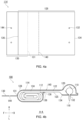
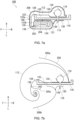
- the second end portion of the cover enveloping portion described above can be joined to the back surface of the cushion folded portion. Joining of the second end portion of the cover enveloping portion to the cushion folded portion and providing the aforementioned second weak portion between this second end portion and the cover extension portion enables smooth release of the airbag cushion.
- the cover enveloping portion may cover the airbag cushion from top to bottom, the cushion rear portion, the cushion folded portion, and the cushion front portion. This enables the cover enveloping portion to uniformly cover all locations of the airbag cushion from top to bottom; therefore, the load applied by the cover enveloping portion on the airbag cushion upon expansion and deployment thereof is also substantially uniform, and this reduces expansion and deployment behavioral bias of the airbag cushion.
- the present invention enables providing a side airbag device that improves occupant restraining performance and can be efficiently stowed inside a vehicle seat.
- FIG. 1 is a diagram illustrating a side airbag device 100 according to an embodiment of the present invention.
- FIG. 1(a) illustrates the airbag cushion 112 in an activated state.
- FIG. 1(a) illustrates from the right side in the vehicle width direction and to the front of the vehicle, the side airbag device 100 and a seat 102 for a vehicle to which the side airbag device 100 is applied.
- the front-back direction with respect to the seat 102 is appropriately indicated by arrows F (Forward) and B (Back), respectively
- the left-right is indicated by arrows L (Left) and R (Right), respectively
- the up-down direction is indicated by arrows U (Up) and D (Down), respectively.
- the upholstery or seat pad (for example, urethane material) of the seatback 104 of the seat 102 is omitted, and only an internal frame 106 is illustrated.
- the internal frame 106 is a member that is a skeleton built into the seatback 104.
- the seat 102 is assumed to be arranged on the left side in the front row.
- the side airbag device 100 can be provided in any seat, in the front row, in the back row, and even on either left or right side of the vehicle.
- the seat 102 normally faces the front of the vehicle, but can also assumed to rotate to face the rear.
- the directions indicated by arrows in each diagram are not intended to be limited to the front-back and left-right directions relative to the vehicle, but rather the front direction is “front” and a back side direction is “back” as viewed from an occupant regularly seated in the seat 102.
- a right hand direction of the occupant at this time is “right” and a left hand direction is “left”.
- a direction toward the head is “up” and a direction toward the leg is "down.”
- the side airbag device 100 uses the airbag cushion 112 to restrain an occupant seated on the seat 102 from the side in an emergency such as when an impact occurs on the vehicle.
- the airbag cushion 112 is a bag-shaped member for capturing an occupant and is formed by overlapping, stitching, and otherwise adhering a plurality of base materials included on the surface thereof or weaving using OPW (one piece woven).
- An inflator 110 is a gas generating device that operates upon receiving an activation signal transmitted from the vehicle side when an impact occurs, and supplies gas to the inside of the airbag cushion 112.
- the inflator 110 used is a cylinder type.
- the inflator 110 is equipped on the rear side of the inside of the airbag cushion 112 with the longitudinal direction thereof facing up and down.
- Examples of currently prevailing inflators include: types which are filled with a gas generating agent and burn the agent to generate gas; types which are filled with compressed gas and supply gas without generating heat; hybrid types which utilize both combustion gas and compressed gas; and the like. Any of these types can be used for the inflator 110.
- FIG. 1(b) is a diagram illustrating the state before activation of the airbag cushion 112 of FIG. 1(a) .
- the airbag cushion 112 prior to activation is equipped in the seatback 104 of the seat 102 in a stowed form such as by rolling or folding.
- the airbag cushion 112 is packaged as an airbag module 108 by inserting the inflator 110 and wrapping with a cover member 114.
- the airbag module 106 is assembled to a frame side plate part 116 of the internal frame 106.
- the frame side plate part 116 is a portion of the internal frame 106 along the left and right side surfaces of the seatback 104.
- the frame side plate part 116 is provided in pairs on the left and right sides in the vehicle width direction.
- the airbag module 106 is assembled to the frame side plate part 116 on the left side in the vehicle width direction. Note that the airbag module 106 can also be assembled to the frame side plate part on the right side in the vehicle width direction.
- the airbag module 106 can be provided either on a side part on a door side (near side) of the seat 102 that is closer to a collision point, or on a side part on an vehicle inner side (far side) of the seat 102 that is farther from the collision point.
- the airbag module 106 includes the cover member 114 that covers the airbag cushion 112 in stowed form.
- the cover member 114 is made of non-woven fabric or the like, encloses the airbag cushion 112 in a stowed form, breaks due to expansion pressure of the airbag cushion 112, and releases the airbag cushion 112.
- FIG. 2 is a diagram illustrating the side airbag device 100 in FIG. 1(b) from the rear of the vehicle.
- FIG. 2(a) illustrates the side airbag device 100 of FIG. 1(b) from the upper left rear side of the seat 102.
- the airbag cushion 112 in the stowed form has a vertically long shape along the frame side plate part 116.
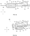
- the airbag module 108 is assembled to the frame side plate part 116 using the stud bolt 118 of the inflator 110 (see FIG. 5(b) ).
- the inflator 110 is inserted into the cushion rear portion 120 described below and attached to the frame side plate part 116 with the main body thereof positioned inside the seat 102 in the width direction.
- a plurality of stud bolt 118 protrude from the main body of the inflator 110, and the inflator 110 is secured by fastening the stud bolt 118 to the frame side plate part 116.
- the tip end of the stud bolt 118 extends through the outside of the frame side plate part 116, and a cover extension portion 130 of the cover member 114 is hooked and fastened to this tip end side.
Landscapes
- Engineering & Computer Science (AREA)
- Mechanical Engineering (AREA)
- Aviation & Aerospace Engineering (AREA)
- Transportation (AREA)
- Air Bags (AREA)
- Seats For Vehicles (AREA)
Claims (8)
- Innenrahmen eines Fahrzeugsitzes (102), umfassend eine Seitenairbagvorrichtung (100), umfassend:ein Airbagmodul (108), das auf dem Rahmenseitenplattenteil (116) entlang der Seitenoberfläche der Sitzlehne (104) des Innenrahmens (106) montiert ist, wobeidas Airbagmodul (108) einschließt:ein Airbagkissen (112), das beutelförmig ist und an dem Rahmenseitenplattenteil (116) in einer vorgeschriebenen verstauten Form, die gerollt oder gefaltet ist, montiert werden kann,einen Gasgenerator (110), der in einer vorgeschriebenen Position des Airbagkissens (112) in der verstauten Form eingesetzt ist, undein Abdeckelement (114), das einen vorgeschriebenen Bereich des Airbagkissens (112) in der verstauten Form umhüllt und durch Expansionsdruck des Airbagkissens (112) zerbrochen werden kann;wobei das Airbagkissen (112) in verstauter Form einschließt:einen Kissenrückabschnitt (120), der den Gasgenerator (110) enthält und im Inneren in Breitenrichtung der Sitzlehne (104) des Rahmenseitenplattenteils (116) montiert ist,einen gefalteten Kissenabschnitt (122), der sich von dem hinteren Kissenabschnitt (120) erstreckt und über die Vorderkante des Rahmenseitenplattenteils (116) und zurück zu der Außenseite des Rahmenseitenplattenteils (116) gefaltet ist, undeinen vorderen Kissenabschnitt (124), der sich von dem gefalteten Kissenabschnitt (122) erstreckt und außerhalb des Rahmenseitenplattenteils (116) angeordnet ist; undwobei das Abdeckelement (114) auf dem horizontalen Querschnitt des Airbagmoduls (108), das an dem Rahmenseitenplattenteil (116) montiert ist, einschließt:einen abdeckungsumhüllenden Abschnitt (128) mit einem ersten Endabschnitt, der mit dem hinteren Kissenabschnitt (120) in Eingriff steht und von der Innenseite in Breitenrichtung dieses hinteren Kissenabschnitts (120) über die vordere Oberfläche des gefalteten Kissenabschnitts (122) und zu dem Rand in Breitenrichtung des vorderen Kissenabschnitts (124) abdeckt;wobei ein Abdeckungsverlängerungsabschnitt (130), der mit einer Region des abdeckungsumhüllenden Abschnitt (128), der den vorderen Kissenabschnitt (124) abdeckt, mittels eines vorgeschriebenen Verlinkungsabschnitts (131) verbunden ist, von diesem Verlinkungsabschnitt (131) vorsteht und mit dem Rahmenseitenplattenteil (116) in Eingriff steht; undein oder mehrere schwache Abschnitte (140,204,222,242), die auf dem abdeckungsumhüllenden Abschnitt (128) oder dem Abdeckungsverlängerungsabschnitt (130) durch Expansionsdruck zerbrochen werden können, dadurch gekennzeichnet, dassder abdeckungsumhüllende Abschnitt (128) einen zweiten Endabschnitt (136) umfasst, der bis zu der hinteren Oberfläche des gefalteten Kissenabschnitts (122) reicht und mit dieser hinteren Oberfläche in Eingriff steht, wobeider eine oder die mehreren schwachen Abschnitte (140,204,222,242) einen ersten schwachen Abschnitt (140,222) umfassen, der in einem Bereich zwischen einem ersten Endabschnitt des abdeckungsumhüllenden Abschnitts (128) und dem Verlinkungsabschnitt (131) bereitgestellt ist, wobeider eine oder die mehreren schwachen Abschnitte (140,204,222,242) einen zweiten schwachen Abschnitt (204) einschließen, der in einer Region des abdeckungsumhüllenden Abschnitts (128) zwischen dem Verlinkungsabschnitt (131) und dem zweiten Endabschnitt (136) bereitgestellt ist, wobeider zweite schwache Abschnitt (204) mittels temporären Vernähens des zweiten Endabschnitts (136) des abdeckungsumhüllenden Abschnitts (128) mit der Rückseite des gefalteten Kissenabschnitts (122), der durch Expansionsdruck geöffnet werden kann, ausgebildet ist.
- Innenrahmen nach Anspruch 1, wobei der erste schwache Abschnitt (140,222) in der Nähe des Verbindungsabschnitts (131) bereitgestellt ist.
- Innenrahmen nach Anspruch 1, wobei der erste schwache Abschnitt (140,222) an einer Position bereitgestellt ist, die sich auf der Vorderseite des Airbagkissens (112) in verstauter Form befindet, wenn das Airbagmodul (108) an dem Rahmenseitenplattenteil (116) montiert ist.
- Innenrahmen nach einem der Ansprüche 1 bis 3, wobei der zweite Endabschnitt (136) des abdeckungsumhüllenden Abschnitts (128) mit der hinteren Oberfläche des gefalteten Kissenabschnitts (122) verlinkt ist.
- Innenrahmen nach einem der Ansprüche 1 bis 4, wobei der eine oder die mehreren schwachen Abschnitte (140,204,222,242) einen dritten schwachen Abschnitt (242) einschließen, der auf dem Abdeckungsverlängerungsabschnitt (130) ausgebildet ist und beim Brechen aufgrund Expansionsdruck den abdeckungsumhüllenden Abschnitt (128) von dem Rahmenseitenplattenteil (116) trennt.
- Innenrahmen nach einem der Ansprüche 1 bis 5, wobei der Abdeckungsverlängerungsabschnitt (130) an einem Stehbolzen (118) des Gasgenerators (110) eingehakt ist, der das Rahmenseitenplattenteil (116) durchdringt.
- Innenrahmen nach einem der Ansprüche 1 bis 6, wobei das Airbagkissen (112) in verstauter Form ferner einen freiliegenden Kissenabschnitt (125) einschließt, der an einer vorgeschriebenen Stelle von dem hinteren Kissenabschnitt (120) zu dem vorderen Kissenabschnitt (124) ausgebildet ist, durch das Abdeckelement (114) freiliegt und mit dem Rahmenseitenplattenteil (116) in Kontakt steht.
- Innenrahmen nach einem der Ansprüche 1 bis 7, wobei der abdeckungsumhüllende Abschnitt (128) das vollständige Airbagkissen (112) von oben bis unten, den hinteren Kissenabschnitt (120), den gefalteten Kissenabschnitt (122) und den vorderen Kissenabschnitt (124) abdeckt.
Applications Claiming Priority (2)
| Application Number | Priority Date | Filing Date | Title |
|---|---|---|---|
| JP2019209528 | 2019-11-20 | ||
| PCT/JP2020/037403 WO2021100335A1 (ja) | 2019-11-20 | 2020-10-01 | サイドエアバッグ装置 |
Publications (3)
| Publication Number | Publication Date |
|---|---|
| EP4063201A1 EP4063201A1 (de) | 2022-09-28 |
| EP4063201A4 EP4063201A4 (de) | 2023-12-13 |
| EP4063201B1 true EP4063201B1 (de) | 2025-02-26 |
Family
ID=75980620
Family Applications (1)
| Application Number | Title | Priority Date | Filing Date |
|---|---|---|---|
| EP20889378.4A Active EP4063201B1 (de) | 2019-11-20 | 2020-10-01 | Innerer stuhlrahmen mit einer seitenairbagvorrichtung |
Country Status (6)
| Country | Link |
|---|---|
| US (1) | US11766983B2 (de) |
| EP (1) | EP4063201B1 (de) |
| JP (1) | JP7290748B2 (de) |
| KR (1) | KR102803045B1 (de) |
| CN (1) | CN114585542B (de) |
| WO (1) | WO2021100335A1 (de) |
Families Citing this family (7)
| Publication number | Priority date | Publication date | Assignee | Title |
|---|---|---|---|---|
| US11780395B2 (en) * | 2019-03-13 | 2023-10-10 | Autoliv Development Ab | Airbag device for driver's seat |
| CN113825678B (zh) * | 2019-05-31 | 2023-07-04 | 奥托立夫开发公司 | 侧安全气囊装置及侧安全气囊装置的制造方法 |
| DE102019121475A1 (de) * | 2019-08-08 | 2021-02-11 | Autoliv Development Ab | Fahrzeugsitzbaugruppe mit einem Fahrzeugsitz und einer Seitengassackbaugruppe und Seitengassackeinheit |
| EP4147918A4 (de) * | 2020-04-09 | 2024-05-01 | Autoliv Development AB | Seitenairbagvorrichtung |
| US12122316B2 (en) * | 2020-10-13 | 2024-10-22 | Autoliv Development Ab | Side airbag device |
| JP7591485B2 (ja) * | 2021-10-23 | 2024-11-28 | オートリブ ディベロップメント エービー | エアバッグ装置及び製造方法 |
| CN116834692B (zh) * | 2023-06-26 | 2026-03-20 | 上海临港均胜汽车安全系统有限公司 | 一种气囊包和气袋的折叠方法 |
Family Cites Families (16)
| Publication number | Priority date | Publication date | Assignee | Title |
|---|---|---|---|---|
| JP3815833B2 (ja) * | 1996-01-17 | 2006-08-30 | 豊田合成株式会社 | 側部用エアバッグ装置 |
| JP2001219808A (ja) * | 2000-02-10 | 2001-08-14 | Toyota Motor Corp | シート内蔵型サイドエアバッグ装置 |
| JP4962185B2 (ja) * | 2007-07-19 | 2012-06-27 | 豊田合成株式会社 | サイドエアバッグ装置 |
| JP2012140044A (ja) * | 2010-12-28 | 2012-07-26 | Toyota Motor Corp | 車両用シート |
| EP2567870B1 (de) * | 2011-09-09 | 2015-03-25 | Autoliv Development AB | Fahrzeugsitz mit einer Airbageinheit |
| US10766450B2 (en) * | 2014-01-27 | 2020-09-08 | Autoliv Development Ab | Side airbag device |
| JP6354044B2 (ja) * | 2015-04-27 | 2018-07-11 | オートリブ ディベロップメント エービー | サイドエアバッグ装置 |
| JP2017094933A (ja) * | 2015-11-24 | 2017-06-01 | タカタ株式会社 | エアバッグ装置 |
| DE102016001942A1 (de) * | 2016-02-19 | 2017-08-24 | Trw Automotive Gmbh | Kopfschutz-Gassackmodul |
| KR20180009415A (ko) * | 2016-07-18 | 2018-01-29 | 현대다이모스(주) | 사이드 에어백 가이드 및 이를 이용한 차량용 사이드 에어백 시트 |
| JP6823079B2 (ja) | 2016-12-05 | 2021-01-27 | オートリブ ディベロップメント エービー | サイドエアバッグ装置 |
| US11104287B2 (en) * | 2016-12-05 | 2021-08-31 | Autoliv Development Ab | Side air bag device |
| DE102017113105A1 (de) | 2017-06-14 | 2018-12-20 | Autoliv Development Ab | Seitengassackmodul und Fahrzeugsitz |
| US11214223B2 (en) * | 2017-11-02 | 2022-01-04 | Autoliv Development Ab | Side airbag device |
| EP3517371B1 (de) * | 2018-01-26 | 2021-11-03 | Autoliv Development AB | Seitenairbagvorrichtung |
| JP6982562B2 (ja) * | 2018-01-26 | 2021-12-17 | オートリブ ディベロップメント エービー | サイドエアバッグ装置 |
-
2020
- 2020-10-01 EP EP20889378.4A patent/EP4063201B1/de active Active
- 2020-10-01 JP JP2021558202A patent/JP7290748B2/ja active Active
- 2020-10-01 KR KR1020227020279A patent/KR102803045B1/ko active Active
- 2020-10-01 US US17/756,105 patent/US11766983B2/en active Active
- 2020-10-01 WO PCT/JP2020/037403 patent/WO2021100335A1/ja not_active Ceased
- 2020-10-01 CN CN202080073462.XA patent/CN114585542B/zh active Active
Also Published As
| Publication number | Publication date |
|---|---|
| US11766983B2 (en) | 2023-09-26 |
| CN114585542A (zh) | 2022-06-03 |
| EP4063201A1 (de) | 2022-09-28 |
| US20220402455A1 (en) | 2022-12-22 |
| KR20220100036A (ko) | 2022-07-14 |
| EP4063201A4 (de) | 2023-12-13 |
| JP7290748B2 (ja) | 2023-06-13 |
| WO2021100335A1 (ja) | 2021-05-27 |
| JPWO2021100335A1 (de) | 2021-05-27 |
| CN114585542B (zh) | 2023-11-24 |
| KR102803045B1 (ko) | 2025-05-07 |
Similar Documents
| Publication | Publication Date | Title |
|---|---|---|
| EP4063201B1 (de) | Innerer stuhlrahmen mit einer seitenairbagvorrichtung | |
| KR102362655B1 (ko) | 사이드 에어백 장치 | |
| EP3549830B1 (de) | Seitenairbagvorrichtung | |
| KR102362071B1 (ko) | 사이드 에어백 장치 | |
| JP6823079B2 (ja) | サイドエアバッグ装置 | |
| JP2018024285A (ja) | エアバッグ装置 | |
| US20200101932A1 (en) | Side airbag apparatus and wrapping material | |
| KR102643556B1 (ko) | 에어백용 보유 지지 커버 및 차량용 에어백 장치 | |
| EP4321393A1 (de) | Insassenrückhaltevorrichtung und herstellungsverfahren für insassenrückhaltevorrichtung | |
| CN117460649A (zh) | 具有辅助展开包裹件的正面安全气囊系统 | |
| KR102408015B1 (ko) | 사이드 에어백 장치 | |
| CN114867636A (zh) | 车辆座椅 | |
| EP4566895A1 (de) | Insassenschutzvorrichtung | |
| EP3808610B1 (de) | Airbagvorrichtung | |
| JP7181484B2 (ja) | 乗物用シート | |
| JP7560503B2 (ja) | 車両用エアバッグ装置 | |
| JP7165015B2 (ja) | 乗員保護装置 | |
| US12291159B2 (en) | Knee airbag device | |
| WO2026063113A1 (ja) | エアバッグ装置 | |
| CN121311393A (zh) | 帘式安全气囊装置 | |
| WO2021002433A1 (ja) | 車両用エアバッグ装置 |
Legal Events
| Date | Code | Title | Description |
|---|---|---|---|
| STAA | Information on the status of an ep patent application or granted ep patent |
Free format text: STATUS: THE INTERNATIONAL PUBLICATION HAS BEEN MADE |
|
| PUAI | Public reference made under article 153(3) epc to a published international application that has entered the european phase |
Free format text: ORIGINAL CODE: 0009012 |
|
| STAA | Information on the status of an ep patent application or granted ep patent |
Free format text: STATUS: REQUEST FOR EXAMINATION WAS MADE |
|
| 17P | Request for examination filed |
Effective date: 20220610 |
|
| AK | Designated contracting states |
Kind code of ref document: A1 Designated state(s): AL AT BE BG CH CY CZ DE DK EE ES FI FR GB GR HR HU IE IS IT LI LT LU LV MC MK MT NL NO PL PT RO RS SE SI SK SM TR |
|
| DAV | Request for validation of the european patent (deleted) | ||
| DAX | Request for extension of the european patent (deleted) | ||
| A4 | Supplementary search report drawn up and despatched |
Effective date: 20231115 |
|
| RIC1 | Information provided on ipc code assigned before grant |
Ipc: B60R 21/201 20110101ALI20231109BHEP Ipc: B60R 21/217 20110101ALI20231109BHEP Ipc: B60N 2/68 20060101ALI20231109BHEP Ipc: B60N 2/42 20060101ALI20231109BHEP Ipc: B60R 21/2338 20110101ALI20231109BHEP Ipc: B60R 21/207 20060101AFI20231109BHEP |
|
| RIC1 | Information provided on ipc code assigned before grant |
Ipc: B60R 21/201 20110101ALI20240815BHEP Ipc: B60R 21/217 20110101ALI20240815BHEP Ipc: B60N 2/68 20060101ALI20240815BHEP Ipc: B60N 2/42 20060101ALI20240815BHEP Ipc: B60R 21/2338 20110101ALI20240815BHEP Ipc: B60R 21/207 20060101AFI20240815BHEP |
|
| GRAP | Despatch of communication of intention to grant a patent |
Free format text: ORIGINAL CODE: EPIDOSNIGR1 |
|
| STAA | Information on the status of an ep patent application or granted ep patent |
Free format text: STATUS: GRANT OF PATENT IS INTENDED |
|
| INTG | Intention to grant announced |
Effective date: 20240920 |
|
| GRAS | Grant fee paid |
Free format text: ORIGINAL CODE: EPIDOSNIGR3 |
|
| GRAA | (expected) grant |
Free format text: ORIGINAL CODE: 0009210 |
|
| STAA | Information on the status of an ep patent application or granted ep patent |
Free format text: STATUS: THE PATENT HAS BEEN GRANTED |
|
| AK | Designated contracting states |
Kind code of ref document: B1 Designated state(s): AL AT BE BG CH CY CZ DE DK EE ES FI FR GB GR HR HU IE IS IT LI LT LU LV MC MK MT NL NO PL PT RO RS SE SI SK SM TR |
|
| REG | Reference to a national code |
Ref country code: GB Ref legal event code: FG4D |
|
| REG | Reference to a national code |
Ref country code: CH Ref legal event code: EP |
|
| REG | Reference to a national code |
Ref country code: DE Ref legal event code: R096 Ref document number: 602020046988 Country of ref document: DE |
|
| REG | Reference to a national code |
Ref country code: IE Ref legal event code: FG4D |
|
| REG | Reference to a national code |
Ref country code: NL Ref legal event code: MP Effective date: 20250226 |
|
| PG25 | Lapsed in a contracting state [announced via postgrant information from national office to epo] |
Ref country code: RS Free format text: LAPSE BECAUSE OF FAILURE TO SUBMIT A TRANSLATION OF THE DESCRIPTION OR TO PAY THE FEE WITHIN THE PRESCRIBED TIME-LIMIT Effective date: 20250526 |
|
| PG25 | Lapsed in a contracting state [announced via postgrant information from national office to epo] |
Ref country code: FI Free format text: LAPSE BECAUSE OF FAILURE TO SUBMIT A TRANSLATION OF THE DESCRIPTION OR TO PAY THE FEE WITHIN THE PRESCRIBED TIME-LIMIT Effective date: 20250226 |
|
| PG25 | Lapsed in a contracting state [announced via postgrant information from national office to epo] |
Ref country code: PL Free format text: LAPSE BECAUSE OF FAILURE TO SUBMIT A TRANSLATION OF THE DESCRIPTION OR TO PAY THE FEE WITHIN THE PRESCRIBED TIME-LIMIT Effective date: 20250226 |
|
| PG25 | Lapsed in a contracting state [announced via postgrant information from national office to epo] |
Ref country code: ES Free format text: LAPSE BECAUSE OF FAILURE TO SUBMIT A TRANSLATION OF THE DESCRIPTION OR TO PAY THE FEE WITHIN THE PRESCRIBED TIME-LIMIT Effective date: 20250226 |
|
| REG | Reference to a national code |
Ref country code: LT Ref legal event code: MG9D |
|
| PG25 | Lapsed in a contracting state [announced via postgrant information from national office to epo] |
Ref country code: NO Free format text: LAPSE BECAUSE OF FAILURE TO SUBMIT A TRANSLATION OF THE DESCRIPTION OR TO PAY THE FEE WITHIN THE PRESCRIBED TIME-LIMIT Effective date: 20250526 Ref country code: IS Free format text: LAPSE BECAUSE OF FAILURE TO SUBMIT A TRANSLATION OF THE DESCRIPTION OR TO PAY THE FEE WITHIN THE PRESCRIBED TIME-LIMIT Effective date: 20250626 |
|
| PG25 | Lapsed in a contracting state [announced via postgrant information from national office to epo] |
Ref country code: NL Free format text: LAPSE BECAUSE OF FAILURE TO SUBMIT A TRANSLATION OF THE DESCRIPTION OR TO PAY THE FEE WITHIN THE PRESCRIBED TIME-LIMIT Effective date: 20250226 |
|
| PG25 | Lapsed in a contracting state [announced via postgrant information from national office to epo] |
Ref country code: HR Free format text: LAPSE BECAUSE OF FAILURE TO SUBMIT A TRANSLATION OF THE DESCRIPTION OR TO PAY THE FEE WITHIN THE PRESCRIBED TIME-LIMIT Effective date: 20250226 |
|
| PG25 | Lapsed in a contracting state [announced via postgrant information from national office to epo] |
Ref country code: PT Free format text: LAPSE BECAUSE OF FAILURE TO SUBMIT A TRANSLATION OF THE DESCRIPTION OR TO PAY THE FEE WITHIN THE PRESCRIBED TIME-LIMIT Effective date: 20250626 Ref country code: LV Free format text: LAPSE BECAUSE OF FAILURE TO SUBMIT A TRANSLATION OF THE DESCRIPTION OR TO PAY THE FEE WITHIN THE PRESCRIBED TIME-LIMIT Effective date: 20250226 |
|
| PG25 | Lapsed in a contracting state [announced via postgrant information from national office to epo] |
Ref country code: BG Free format text: LAPSE BECAUSE OF FAILURE TO SUBMIT A TRANSLATION OF THE DESCRIPTION OR TO PAY THE FEE WITHIN THE PRESCRIBED TIME-LIMIT Effective date: 20250226 Ref country code: GR Free format text: LAPSE BECAUSE OF FAILURE TO SUBMIT A TRANSLATION OF THE DESCRIPTION OR TO PAY THE FEE WITHIN THE PRESCRIBED TIME-LIMIT Effective date: 20250527 |
|
| REG | Reference to a national code |
Ref country code: AT Ref legal event code: MK05 Ref document number: 1770354 Country of ref document: AT Kind code of ref document: T Effective date: 20250226 |
|
| PG25 | Lapsed in a contracting state [announced via postgrant information from national office to epo] |
Ref country code: SE Free format text: LAPSE BECAUSE OF FAILURE TO SUBMIT A TRANSLATION OF THE DESCRIPTION OR TO PAY THE FEE WITHIN THE PRESCRIBED TIME-LIMIT Effective date: 20250226 |
|
| PG25 | Lapsed in a contracting state [announced via postgrant information from national office to epo] |
Ref country code: SM Free format text: LAPSE BECAUSE OF FAILURE TO SUBMIT A TRANSLATION OF THE DESCRIPTION OR TO PAY THE FEE WITHIN THE PRESCRIBED TIME-LIMIT Effective date: 20250226 |
|
| PG25 | Lapsed in a contracting state [announced via postgrant information from national office to epo] |
Ref country code: DK Free format text: LAPSE BECAUSE OF FAILURE TO SUBMIT A TRANSLATION OF THE DESCRIPTION OR TO PAY THE FEE WITHIN THE PRESCRIBED TIME-LIMIT Effective date: 20250226 |
|
| PG25 | Lapsed in a contracting state [announced via postgrant information from national office to epo] |
Ref country code: IT Free format text: LAPSE BECAUSE OF FAILURE TO SUBMIT A TRANSLATION OF THE DESCRIPTION OR TO PAY THE FEE WITHIN THE PRESCRIBED TIME-LIMIT Effective date: 20250226 |
|
| PG25 | Lapsed in a contracting state [announced via postgrant information from national office to epo] |
Ref country code: AT Free format text: LAPSE BECAUSE OF FAILURE TO SUBMIT A TRANSLATION OF THE DESCRIPTION OR TO PAY THE FEE WITHIN THE PRESCRIBED TIME-LIMIT Effective date: 20250226 |
|
| PG25 | Lapsed in a contracting state [announced via postgrant information from national office to epo] |
Ref country code: EE Free format text: LAPSE BECAUSE OF FAILURE TO SUBMIT A TRANSLATION OF THE DESCRIPTION OR TO PAY THE FEE WITHIN THE PRESCRIBED TIME-LIMIT Effective date: 20250226 Ref country code: CZ Free format text: LAPSE BECAUSE OF FAILURE TO SUBMIT A TRANSLATION OF THE DESCRIPTION OR TO PAY THE FEE WITHIN THE PRESCRIBED TIME-LIMIT Effective date: 20250226 |
|
| PG25 | Lapsed in a contracting state [announced via postgrant information from national office to epo] |
Ref country code: RO Free format text: LAPSE BECAUSE OF FAILURE TO SUBMIT A TRANSLATION OF THE DESCRIPTION OR TO PAY THE FEE WITHIN THE PRESCRIBED TIME-LIMIT Effective date: 20250226 |
|
| PG25 | Lapsed in a contracting state [announced via postgrant information from national office to epo] |
Ref country code: SK Free format text: LAPSE BECAUSE OF FAILURE TO SUBMIT A TRANSLATION OF THE DESCRIPTION OR TO PAY THE FEE WITHIN THE PRESCRIBED TIME-LIMIT Effective date: 20250226 |
|
| REG | Reference to a national code |
Ref country code: DE Ref legal event code: R097 Ref document number: 602020046988 Country of ref document: DE |
|
| PLBE | No opposition filed within time limit |
Free format text: ORIGINAL CODE: 0009261 |
|
| STAA | Information on the status of an ep patent application or granted ep patent |
Free format text: STATUS: NO OPPOSITION FILED WITHIN TIME LIMIT |
|
| PGFP | Annual fee paid to national office [announced via postgrant information from national office to epo] |
Ref country code: DE Payment date: 20251028 Year of fee payment: 6 |
|
| PGFP | Annual fee paid to national office [announced via postgrant information from national office to epo] |
Ref country code: GB Payment date: 20251023 Year of fee payment: 6 |
|
| PGFP | Annual fee paid to national office [announced via postgrant information from national office to epo] |
Ref country code: FR Payment date: 20251027 Year of fee payment: 6 |
|
| 26N | No opposition filed |
Effective date: 20251127 |