EP4058239B1 - Werkstückhaltevorrichtung für eine schleifmaschine und schleifverfahren - Google Patents
Werkstückhaltevorrichtung für eine schleifmaschine und schleifverfahren Download PDFInfo
- Publication number
- EP4058239B1 EP4058239B1 EP20811053.6A EP20811053A EP4058239B1 EP 4058239 B1 EP4058239 B1 EP 4058239B1 EP 20811053 A EP20811053 A EP 20811053A EP 4058239 B1 EP4058239 B1 EP 4058239B1
- Authority
- EP
- European Patent Office
- Prior art keywords
- workpiece
- workrest
- workrests
- grinding
- chuck
- Prior art date
- Legal status (The legal status is an assumption and is not a legal conclusion. Google has not performed a legal analysis and makes no representation as to the accuracy of the status listed.)
- Active
Links
Images


Classifications
-
- B—PERFORMING OPERATIONS; TRANSPORTING
- B23—MACHINE TOOLS; METAL-WORKING NOT OTHERWISE PROVIDED FOR
- B23Q—DETAILS, COMPONENTS, OR ACCESSORIES FOR MACHINE TOOLS, e.g. ARRANGEMENTS FOR COPYING OR CONTROLLING; MACHINE TOOLS IN GENERAL CHARACTERISED BY THE CONSTRUCTION OF PARTICULAR DETAILS OR COMPONENTS; COMBINATIONS OR ASSOCIATIONS OF METAL-WORKING MACHINES, NOT DIRECTED TO A PARTICULAR RESULT
- B23Q3/00—Devices holding, supporting, or positioning work or tools, of a kind normally removable from the machine
- B23Q3/15—Devices for holding work using magnetic or electric force acting directly on the work
-
- B—PERFORMING OPERATIONS; TRANSPORTING
- B24—GRINDING; POLISHING
- B24B—MACHINES, DEVICES, OR PROCESSES FOR GRINDING OR POLISHING; DRESSING OR CONDITIONING OF ABRADING SURFACES; FEEDING OF GRINDING, POLISHING, OR LAPPING AGENTS
- B24B41/00—Component parts such as frames, beds, carriages, headstocks
- B24B41/06—Work supports, e.g. adjustable steadies
- B24B41/061—Work supports, e.g. adjustable steadies axially supporting turning workpieces, e.g. magnetically, pneumatically
-
- B—PERFORMING OPERATIONS; TRANSPORTING
- B24—GRINDING; POLISHING
- B24B—MACHINES, DEVICES, OR PROCESSES FOR GRINDING OR POLISHING; DRESSING OR CONDITIONING OF ABRADING SURFACES; FEEDING OF GRINDING, POLISHING, OR LAPPING AGENTS
- B24B41/00—Component parts such as frames, beds, carriages, headstocks
- B24B41/06—Work supports, e.g. adjustable steadies
- B24B41/065—Steady rests
-
- B—PERFORMING OPERATIONS; TRANSPORTING
- B24—GRINDING; POLISHING
- B24B—MACHINES, DEVICES, OR PROCESSES FOR GRINDING OR POLISHING; DRESSING OR CONDITIONING OF ABRADING SURFACES; FEEDING OF GRINDING, POLISHING, OR LAPPING AGENTS
- B24B41/00—Component parts such as frames, beds, carriages, headstocks
- B24B41/06—Work supports, e.g. adjustable steadies
- B24B41/067—Work supports, e.g. adjustable steadies radially supporting workpieces
-
- B—PERFORMING OPERATIONS; TRANSPORTING
- B24—GRINDING; POLISHING
- B24B—MACHINES, DEVICES, OR PROCESSES FOR GRINDING OR POLISHING; DRESSING OR CONDITIONING OF ABRADING SURFACES; FEEDING OF GRINDING, POLISHING, OR LAPPING AGENTS
- B24B5/00—Machines or devices designed for grinding surfaces of revolution on work, including those which also grind adjacent plane surfaces; Accessories therefor
- B24B5/18—Machines or devices designed for grinding surfaces of revolution on work, including those which also grind adjacent plane surfaces; Accessories therefor involving centreless means for supporting, guiding, floating or rotating work
- B24B5/307—Means for supporting work
-
- B—PERFORMING OPERATIONS; TRANSPORTING
- B23—MACHINE TOOLS; METAL-WORKING NOT OTHERWISE PROVIDED FOR
- B23B—TURNING; BORING
- B23B2215/00—Details of workpieces
- B23B2215/12—Bearing races
-
- B—PERFORMING OPERATIONS; TRANSPORTING
- B24—GRINDING; POLISHING
- B24B—MACHINES, DEVICES, OR PROCESSES FOR GRINDING OR POLISHING; DRESSING OR CONDITIONING OF ABRADING SURFACES; FEEDING OF GRINDING, POLISHING, OR LAPPING AGENTS
- B24B5/00—Machines or devices designed for grinding surfaces of revolution on work, including those which also grind adjacent plane surfaces; Accessories therefor
- B24B5/02—Machines or devices designed for grinding surfaces of revolution on work, including those which also grind adjacent plane surfaces; Accessories therefor involving centres or chucks for holding work
- B24B5/12—Machines or devices designed for grinding surfaces of revolution on work, including those which also grind adjacent plane surfaces; Accessories therefor involving centres or chucks for holding work for grinding cylindrical surfaces both externally and internally with several grinding wheels
Definitions
- JP-A-2017-64841 discloses a grinding device for grinding an outer peripheral surface and an inner peripheral surface of an annular workpiece.
- the assembly includes first and second separate sets of workrests for engaging with the outer circumferential surface of an annular workpiece held by the chuck with a transverse side surface in engagement with the chuck, wherein the first and second sets of workrests are configurable as the workrests of at least one of the first and second sets of workrests are movable workrests which are movable relative to the chuck rotational axis independently of the workrests of the other set such that:
- the grinding of an inner circumferential surface may generate much higher forces in a direction which might otherwise push the part away from workrests in known configurations, as the strength of a magnetic chuck may be insufficient to safely retain the workpiece.
- the location(s) of one or more movable workrests may be adjusted between different grinding operations.
- the location(s) may be adjusted between the steps of grinding the outer and inner (or vice versa) circumferential surfaces of the workpiece.
- each workrest actuator is operable to move the respective workrest (or set of workrests) in a linear manner relative to its workrest support.
- Each workrest actuator may be operable to move the respective workrest along a linear reference axis
- each workrest actuator may include a drive assembly having a driven member which is coupled to the workrest, and the linear reference axis may extend through the driven member and the workrest.
- each workrest actuator includes a drive assembly having a driven member which is coupled to the workrest and is slideable relative to an actuator body between advanced and retracted positions.
- the driven member and actuator body may define complementary frustoconical surfaces which engage each other when the supporting member is in its advanced position.
- the frustoconical surfaces may taper inwardly in a direction towards the workrest.
- the complementary surfaces may provide a kinematic coupling between the driven member and the actuator body to ensure reliable and precise location of the respective workrest when it is in its advanced position.
- each workrest actuator may be operable to move the respective workrest (or set of workrests) in a rotary manner relative to its workrest support.
- each of the first and second sets of workrests consists of two workrests.
- the workpiece holding assembly may include four workrests only.
- a first set of workrests (for use during grinding of an outer circumferential surface of a workpiece) may include one workrest at a location between 140 and 160° (preferably around 150°) from the circumferential position relative to the chuck rotational axis at which a grinding wheel contacts a workpiece held by the chuck (measured clockwise or anticlockwise).
- the second set may include another workrest at a location between 50 and 70° (preferably around 60°) from the circumferential position relative to the chuck rotational axis at which a grinding wheel contacts a workpiece held by the chuck (measured clockwise or anticlockwise, but in the same sense as the one workrest).
- a second set of workrests (for use during grinding of an inner circumferential surface of a workpiece) may include a workrest at a location between 170 and 190° (preferably around 180°) from the circumferential position relative to the chuck rotational axis at which a grinding wheel in use contacts a workpiece held by the chuck.
- the second set may include another workrest at a location between 80 and 100° (preferably around 90°) from the circumferential position relative to the chuck rotational axis at which a grinding wheel contacts a workpiece held by the chuck (measured clockwise or anticlockwise).
- the grinding machine may include a grinding wheel having a grinding surface comprising CBN material.
- the grinding wheel rotates in a direction opposite to the first workpiece rotation direction during grinding of the outer circumferential surface, and the grinding wheel rotates in the same direction as the first workpiece rotation direction during grinding of the inner circumferential surface. In this way, climb grinding may be carried out, with the workpiece and grinding wheel surfaces moving in the same direction.
- the grinding wheel rotates in the same direction as the first workpiece rotation direction during grinding of the outer circumferential surface, and the grinding wheel rotates in a direction opposite to the first workpiece rotation direction during grinding of the inner circumferential surface. In this way, an up-cutting grinding process may be carried out, with the workpiece and grinding wheel surfaces moving in opposite directions.
- the location of the point of contact between a grinding wheel and the workpiece may also be adjusted in a circumferential direction around the workpiece to improve the reliability of retention of a workpiece by the workpiece holding assembly.
- Each workrest may have a workpiece engagement surface which is radially spaced (offset) from a locus defined by the outer circumferential surface of the workpiece when the workpiece is located with the workpiece central axis coaxial with the chuck rotational axis. These offsets may be selected to allow a workpiece to move clear of one set of workrests when moved into engagement with another set of workrests.
- the workrests of the first set may be offset such that when the workpiece is engaged with the workrests of the first set and the chuck rotates in a chuck rotation direction, a resultant force is exerted on the workpiece which urges it towards the first set of workrests.
- the workrests of the second set may be offset such that when the workpiece is engaged with the workrests of the second set and the chuck rotates in a direction opposite to said chuck rotation direction, a resultant force is exerted on the workpiece which urges it towards the second set of workrests.
- the workrests of the first and second sets of workrests may be located in the same positions relative to the chuck during the step of grinding the outer circumferential surface of the workpiece as during the step of grinding the inner circumferential surface of the workpiece.
- the workrests of at least one of the first and second sets of workrests may be located in different positions relative to the chuck during the step of grinding the outer circumferential surface of the workpiece from their positions relative to the chuck during the step of grinding the inner circumferential surface of the workpiece.
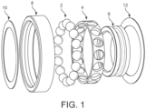
- the assembly and methods described herein may be suitable for use in grinding a range of workpieces having inner and outer circumferential surfaces which have a circular cross-section in a plane perpendicular to the workpiece central axis.
- the workpieces may be in the form of a thin ring or sleeve, such as a bearing raceway of a rolling element bearing.
- the outer circumferential surface may be radially outwardly facing relative to the workpiece central axis.
- the inner circumferential surface may be radially inwardly facing relative to the workpiece central axis.
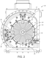
- a workpiece holding assembly 20 is shown in Figure 2 . It includes a magnetic chuck 22 and a drive (not shown) for rotating the chuck about a chuck rotational axis 24 which is perpendicular to the plane of the drawing.
- the magnetic chuck drive is carried by an assembly body 21 which provides a support structure for the assembly. In use the assembly body is mounted onto a machine base of a machine tool (not shown).
- FIGS 3 and 4 schematically illustrate grinding of an annular workpiece 40 using a grinding wheel 42.
- a first set of workrests comprises first and second lower workrests 26, 28 and a second set of workrests comprises first and second upper workrests 30, 32.
- the workrests may be in the form of finger supports. They may be selectively fixed in position relative to the magnetic chuck.
- Each workrest may include an adjustable slide to facilitate fine adjustment of the location of the workpiece engagement surface of each workrest relative to the magnetic chuck.
- the workrests are arranged such that the location of workrest 26 is adjustable by its slide in a horizontal direction (that is, parallel to the reference plane of the machine base).
- the workrests 28, 30 and 32 are adjustable using their respective slides in radial directions relative to the chuck rotational axis.
- a first set of workrests comprises two lower workrests which are lower than the chuck rotational axis in use when the workpiece holding assembly is mounted on a grinding machine.
- the first lower workrest 26 is located at a radial position relative to the chuck rotational axis 24 which is in a range of 120 to 180° measured in a circumferential direction from a vertical reference line extending from the chuck rotational axis.
- the first lower workrest is located at a radial position around 150° from the vertical reference line.
- the second lower workrest 28 is located at a radial position relative to the chuck rotational axis which is in a range of 210 to 270° measured in the same circumferential direction from a vertical reference line extending from the chuck rotational axis.
- the second lower workrest may be located at a radial position around 240° from the reference line.
- the lower workrests may be located at approximately 5 o'clock and 8 o'clock relative to the magnetic chuck rotational axis 24.
- the pair of upper workrests may be located at approximately 9 o'clock and 12 o'clock relative to the magnetic chuck. It will be appreciated that the radial orientations of the workrests may alternatively correspond to these positions when reflected through vertical or horizontal planes of symmetry passing through the chuck rotational axis.
- a workpiece is then loaded approximately centrally within the four workrests and gripped by the magnetic chuck.
- the workpiece 40 is loaded into a position where its central axis is displaced slightly from the chuck rotational axis 24 in a direction generally towards the pair of workrests to be contacted in the next grinding operation.
- the magnetic chuck drive is then set to rotate the magnetic chuck in a direction dependent on the subsequent grinding operation.
- the workpiece is caused to move across the face of the chuck against the magnetic holding force by the centrifugal action on the offset workpiece, and into contact with one of the pairs of workrest shoes in preparation for a rotating grinding wheel to be brought into contact with the workpiece.
- the workpiece is further caused to be secured in contact with the pair of workrests by grinding forces exerted on the workpiece by the grinding wheel.
- the grinding wheel In the grinding operation, the grinding wheel may be brought into contact with an outer circumferential surface of a workpiece. In another grinding operation on the workpiece, the grinding wheel may be brought into contact with an inner circumferential surface of the workpiece.
- the workrests may be configured such that reversing the direction of rotation of the chuck causes the workpiece to move from one set of workrests to the other automatically between grinds, without requiring any other intervention. This may simplify the process of switching between grinding the inner and outer surfaces of the workpiece and reduce the time taken to switch between the two grinds.
- the grinding wheel is machining an outer circumferential surface of the workpiece.
- the workpiece is rotated clockwise by the magnetic chuck 22 as indicated by arrow 44.
- the grinding wheel 42 is rotated anti-clockwise as indicated by arrow 46.
- the workpiece is urged into contact with the lower workrests 26 and 28.
- a grinding force is created during material removal by locating the central axis of the grinding wheel above that of the workpiece. This urges the workpiece towards the lower workrests.
- the workpiece is machined by climb grinding, with the workpiece and wheel surfaces moving in the same direction.
- Figure 4 illustrates an operation to grind an inner circumferential surface of the workpiece 40.
- the workpiece is rotated anti-clockwise (when viewed in Figure 4 ) as indicated by arrow 50 so as to cause the workpiece to be moved into contact with the workrests 30 and 32.
- the grinding wheel 42 is brought into contact with the inner circumferential surface of the workpiece. It is located on the opposite side of the workpiece in the radial direction to the workrest 30.
- the grinding wheel is rotated anti-clockwise as indicated by arrow 52.
- the central axis of the grinding wheel is located below that of the workpiece which urges the workpiece into engagement with the workrests 30 and 32.
- the inner circumferential surface is ground by climb grinding, with the workpiece and wheel surfaces moving in the same direction.
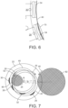
- Circle 60 indicates the location occupied by the workpiece when its central axis is coincident with the chuck rotational axis 24.
- the workpiece is rotated clockwise by the chuck and is in contact with the lower set of workrests 26 and 28. In this location, it is displaced from the position of circle 60 to the position of circle 60' (in a radial direction corresponding to around 4 o'clock relative to the central axis of the chuck when viewed as shown in Figure 5 ).
- the workpiece When grinding the inner circumferential surface, the workpiece is rotated anti-clockwise and is in contact with the upper set of workrests 30 and 32. In this location, it is displaced from the position of circle 60 to the position of circle 60" (in a radial direction corresponding to around 2 o'clock relative to the central axis of the chuck when viewed as shown in Figure 5 ). These offsets cause the workpiece to be urged towards the respective sets of workpieces when the chuck is rotated as indicated above.
- workpiece 40 is shown in the location intended for grinding of its inner circumferential surface. In order to carry out this grind, it is supported by the upper workrests 30 and 32. However, in the region 70 marked in the drawing, it can be seen that the lower workrest 28 (in the position desired during grinding the outer circumferential surface of the workpiece) interferes with the desired intended positioning of the workpiece.
- FIG. 7 The workrest configuration depicted in the schematic drawing of Figure 7 differs from that of preceding drawings in that workrest 32 of the first set of workrests is in a location diametrically opposite to that shown in preceding drawings.
- a workpiece 40 is shown in two offset locations desired during grinding of its inner and outer circumferential surfaces. These offsets and the associated displacements of the workrests are exaggerated in this drawing for the purposes of illustration. In practice, the offsets may be very small. It can be seen that when workpiece 40 is in engagement with workrests 30 and 32 during grinding of its inner circumferential surface by grinding wheel 80, workrest 28 interferes with its desired location. Similarly, with the workpiece in engagement with workrests 26 and 28 or grinding of its outer circumferential surface by the grinding wheel 82, workrest 32 of the other set interferes with the desired position for the workpiece.
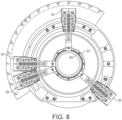
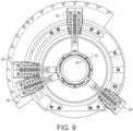
- Figures 8 and 9 show a workpiece holding assembly with its workrests in two different configurations.
- the workrests are in a configuration suitable for holding a workpiece 40 during grinding of its inner circumferential surface.
- Workrests 30 and 32 are in their advanced positions and in contact with the workpiece.
- Workrests 26 and 28 are in their retracted positions, spaced from the outer circumferential surface of the workpiece (by around 6mm in this example).
- the workrests are in a configuration suitable for holding the workpiece 40 during grinding of its outer circumferential surface.
- workrests 30 and 32 are in their retracted positions, spaced from the outer circumferential surface workpiece (by around 6mm in this example).
- Workrests 26 and 28 are in their advanced positions and in contact with the workpiece.
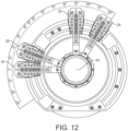
- FIG. 12 and 13 Further workpiece holding assemblies are shown in Figures 12 and 13 to illustrate other variations in the circumferential arrangement of the workrests which are also suitable for supporting a workpiece during grinding of its inner and outer circumferential surfaces.
- the arrangement shown in Figure 12 corresponds to that of Figure 10 when reflected in a horizontal plane extending through the chuck rotational axis 24.
- the arrangement shown in Figure 13 corresponds to that of Figure 12 when reflected in a vertical plane extending through the chuck rotational axis 24.
- the arrangements of Figures 12 and 13 may be preferable in machine tool configurations where it would be advantageous to locate the workrests away from the lower region of the workpiece holding assembly, for example to avoid conflict with other parts of the machine tool.
- the central axis of the grinding wheel is preferably located below that of the workpiece during grinding of both the inner and outer surfaces of the workpiece, so as to drive the workpiece towards the respective workrests during each grind.
- the grinding wheel moves right to left to grind the workpiece in Figure 12 and left to right in Figure 13 .
- the direction in which a workpiece central axis is offset from the magnetic chuck rotational axis during grinding determines the direction of the resultant force on the workpiece during grinding. If the chuck is rotated clockwise (when viewed from the workpiece mounting side), a workpiece offset to the right leads to a downward force, a workpiece offset to the left leads to an upward force, an upward offset leads to a force to the right, and a downward offset leads to a force to the left.
- a workpiece offset to the left leads to a downward force
- a workpiece offset to the right leads to an upward force
- an upward offset leads to a force to the left
- a downward offset leads to a force to the right.
- the workrests of each set may be positioned as appropriate to correspond to the desired offset and counteract the associated resultant force on the workpiece.
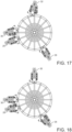
- Figures 17 and 18 illustrate a workpiece holding assembly having a circumferential arrangement of workrests similar to that shown in Figure 8 .
- the workrests are movable between retracted and advanced positions using workrest actuation assemblies which operate in a rotary manner.
- Figures 19 to 22 relate to a workrest actuation assembly 110 for mechanically switching a workrest in a rotary manner between advanced and retracted positions as illustrated by Figures 17 and 18 .
- the assembly 110 includes a pair of shoe arm clamp blocks 112 for clamping a workrest finger support (not shown) therebetween.
- the shoe arm clamp blocks are mounted on an upper shoe support plate 114.
- the assembly also includes a lower support plate 116. In use, the assembly is fixed to a supporting surface using securing bolts 118.
Landscapes
- Engineering & Computer Science (AREA)
- Mechanical Engineering (AREA)
- Grinding Of Cylindrical And Plane Surfaces (AREA)
- Constituent Portions Of Griding Lathes, Driving, Sensing And Control (AREA)
- Machine Tool Units (AREA)
Claims (17)
- Werkstückhalteanordnung (20) für eine Schleifmaschine, die Anordnung umfassend:einen Magnetspanner (22) zum Halten eines Werkstücks (40), das eine äußere Umfangsoberfläche und eine innere Umfangsoberfläche aufweist, die sich konzentrisch um eine Werkstückmittelachse herum befinden; undeinen Spannerantrieb zum Drehen des Spanners um eine Spannerdrehachse (24) während eines Schleifens,dadurch gekennzeichnet, dassdie Anordnung erste und zweite separate Sätze von Werkstückauflagen (26, 28, 30, 32) zum Ineingriffnehmen der äußeren Umfangsoberfläche eines ringförmigen Werkstücks einschließt, das durch den Spanner gehalten wird, wobei eine quer verlaufende Seitenoberfläche mit dem Spanner in Eingriff steht,wobei der erste und der zweite Satz von Werkstückauflagen konfigurierbar sind, dass die Werkstückauflagen von mindestens einem des ersten und des zweiten Satzes von Werkstückauflagen bewegbare Werkstückauflagen sind, die relativ zu der Spannerdrehachse unabhängig von den Werkstückauflagen des anderen Satzes derart bewegbar sind, dass:wenn die äußere Umfangsoberfläche des Werkstücks durch eine Schleifscheibe (42, 82) geschliffen wird, die sich in einer Schleifscheibendrehrichtung dreht, wobei sich der Spanner in einer Spannerdrehrichtung dreht, die äußere Umfangsoberfläche nur in Kontakt mit dem ersten Satz (26, 28) des ersten und des zweiten Satzes von Werkstückauflagen gedrückt wird; undwenn eine innere Umfangsoberfläche des Werkstücks durch eine Schleifscheibe (42,80) geschliffen wird, die sich in der Schleifscheibendrehrichtung dreht, wobei die Drehrichtung des Spanners während des Schleifens der äußeren Umfangsoberfläche relativ zu der Spannerdrehrichtung umgekehrt ist, die äußere Umfangsoberfläche nur in Kontakt mit dem zweiten Satz (30, 32) des ersten und des zweiten Satzes von Werkstückauflagen gedrückt wird.
- Werkstückhalteanordnung nach Anspruch 1, wobei jede der Werkstückauflagen (26, 28, 30, 32) von mindestens einem des ersten und des zweiten Satzes von Werkstückauflagen über eine Kopplung (90, 110, 130) mit der Anordnung gekoppelt ist, die den Werkstückauflagen ermöglicht, zwischen zuvor bestimmten vorgezogenen und zurückgezogenen Positionen relativ zu der Spannerdrehachse (24) umzuschalten.
- Werkstückhalteanordnung nach Anspruch 1 oder 2, wobei jede bewegbare Werkstückauflage (26, 28, 30, 32) mit einer jeweiligen Werkstückauflagenstütze gekoppelt ist und ein Werkstückauflagenaktuator (96, 122, 134) in Verbindung mit jeder bewegbaren Werkstückauflage bereitgestellt ist, wobei jeder Werkstückauflagenaktuator betriebsfähig ist, um die jeweilige Werkstückauflage relativ zu ihrer Werkstückauflagenstütze zu bewegen.
- Werkstückhalteanordnung nach Anspruch 3, sofern dieser von Anspruch 2 abhängig ist, wobei jeder Werkstückauflagenaktuator (96, 122, 134) betriebsfähig ist, um die jeweilige Werkstückauflage zwischen ihrer vorgezogenen und zurückgezogenen Position umzuschalten.
- Werkstückhalteanordnung nach Anspruch 3 oder 4, wobei jeder Werkstückauflagenaktuator (96, 134) betriebsfähig ist, um die jeweilige Werkstückauflage in einer linearen Weise relativ zu ihrer Werkstückauflagenstütze zu bewegen.
- Werkstückhalteanordnung nach Anspruch 5, wobei jeder Werkstückauflagenaktuator (134) betriebsfähig ist, um die jeweilige Werkstückauflage (142) entlang einer linearen Referenzachse (150) zu bewegen, wobei jeder Werkstückauflagenaktuator eine Antriebsanordnung einschließt, die ein angetriebenes Element (132) aufweist, das mit der Werkstückauflage gekoppelt ist, und sich die lineare Referenzachse durch das angetriebene Element und die Werkstückauflage erstreckt.
- Werkstückhalteanordnung nach Anspruch 5 oder 6, wobei jeder Werkstückauflagenaktuator (134) eine Antriebsanordnung einschließt, die ein angetriebenes Element (132) aufweist, das mit der Werkstückauflage gekoppelt ist und relativ zu einem Aktuatorkörper (144) zwischen einer vorgezogenen und einer zurückgezogenen Position verschiebbar ist, und das angetriebene Element und der Aktuatorkörper komplementäre kegelstumpfförmige Oberflächen (146, 148) definieren, die einander in Eingriff nehmen, wenn sich das angetriebene Element in seiner vorgezogenen Position befindet.
- Werkstückhalteanordnung nach Anspruch 7, sofern dieser von Anspruch 6 abhängig ist, wobei eine Mittelreferenzachse der kegelstumpfförmigen Oberflächen mit der linearen Referenzachse (150) zusammenfällt.
- Werkstückhalteanordnung nach Anspruch 3 oder 4, wobei jeder Werkstückauflagenaktuator (122) betriebsfähig ist, um die jeweilige Werkstückauflage relativ zu ihrer Werkstückauflagenstütze in einer sich drehenden Weise zu bewegen.
- Werkstückhaltevorrichtung nach einem der vorstehenden Ansprüche, wobei jeder des ersten und des zweiten Satzes von Werkstückauflagen (26, 28, 30, 32) aus zwei Werkstückauflagen besteht.
- Schleifmaschine, die eine Maschinenbasis und eine Werkstückhalteanordnung (20) nach einem der vorstehenden Ansprüche einschließt, die durch die Maschinenbasis getragen wird, wobei die Maschine vorzugsweise eine Schleifscheibe (40, 80, 82) einschließt, die eine Schleifoberfläche aufweist, umfassend CBN-Material.
- Verfahren zum Schleifen eines Werkstücks (40), das eine äußere Umfangsoberfläche und eine innere Umfangsoberfläche aufweist, unter Verwendung einer Werkstückhalteanordnung (20) nach einem der Ansprüche 1 bis 10 zum Halten des Werkstücks, das Verfahren umfassend die Schritte:Drehen des Werkstücks in einer ersten Werkstückdrehrichtung (44) während des Schleifens der äußeren Umfangsoberfläche mit einer Schleifscheibe (42, 82), die sich in einer Schleifscheibendrehrichtung (46) dreht; undDrehen des Werkstücks in einer zweiten Werkstückdrehrichtung (50), die der ersten Werkstückdrehrichtung entgegengesetzt ist, während des Schleifens der inneren Umfangsoberfläche, wobei sich die Schleifscheibe (42, 80) in der Schleifscheibendrehrichtung dreht.
- Verfahren nach Anspruch 12, wobei sich die Schleifscheibe während des Schleifens der äußeren Umfangsoberfläche in eine Richtung (46) dreht, die der ersten Werkstückdrehrichtung (44) entgegengesetzt ist; und
sich die Schleifscheibe während des Schleifens der inneren Umfangsoberfläche in die gleiche Richtung (52) wie die erste Werkstückdrehrichtung (50) dreht. - Verfahren nach Anspruch 12, wobei sich die Schleifscheibe während des Schleifens der äußeren Umfangsoberfläche in die gleiche Richtung wie die erste Werkstückdrehrichtung dreht; und
sich die Schleifscheibe während des Schleifens der inneren Umfangsoberfläche in eine Richtung dreht, die der ersten Werkstückdrehrichtung entgegengesetzt ist. - Verfahren nach einem der Ansprüche 12 bis 14, wobei jede Werkstückauflage eine Werkstückeingriffsoberfläche aufweist, die radial von einer Ortskurve (60) beabstandet ist, die durch die äußere Umfangsoberfläche des Werkstücks definiert ist, wenn das Werkstück eingerichtet ist, dass die Werkstückmittelachse koaxial zu der Spannerdrehachse (24) ist.
- Verfahren nach einem der Ansprüche 12 bis 15, wobei sich die Werkstückauflagen (26, 28, 30, 32) des ersten und des zweiten Satzes von Werkstückauflagen während des Schritts des Schleifens der äußeren Umfangsoberfläche des Werkstücks in derselben Position relativ zu dem Spanner (22) befinden wie während des Schritts des Schleifens der inneren Umfangsoberfläche des Werkstücks.
- Verfahren nach einem der Ansprüche 12 bis 15, wobei sich die Werkstückauflagen (26, 28, 30, 32) von mindestens einem des ersten und des zweiten Satzes von Werkstückauflagen während des Schritts des Schleifens der äußeren Umfangsoberfläche des Werkstücks in unterschiedlichen Positionen relativ zu dem Spanner (22) angeordnet sind, relativ zu ihren Positionen relativ zu dem Spanner während des Schritts des Schleifens der inneren Umfangsoberfläche des Werkstücks.
Applications Claiming Priority (3)
| Application Number | Priority Date | Filing Date | Title |
|---|---|---|---|
| GBGB1916639.6A GB201916639D0 (en) | 2019-11-15 | 2019-11-15 | A workpiece holding assembly for a grinding machine and grinding methods |
| GB2016217.8A GB2590766B (en) | 2019-11-15 | 2020-10-13 | A workpiece holding assembly for a grinding machine and grinding methods |
| PCT/GB2020/052877 WO2021094756A1 (en) | 2019-11-15 | 2020-11-12 | A workpiece holding assembly for a grinding machine and grinding methods |
Publications (3)
| Publication Number | Publication Date |
|---|---|
| EP4058239A1 EP4058239A1 (de) | 2022-09-21 |
| EP4058239B1 true EP4058239B1 (de) | 2025-04-09 |
| EP4058239C0 EP4058239C0 (de) | 2025-04-09 |
Family
ID=69063244
Family Applications (1)
| Application Number | Title | Priority Date | Filing Date |
|---|---|---|---|
| EP20811053.6A Active EP4058239B1 (de) | 2019-11-15 | 2020-11-12 | Werkstückhaltevorrichtung für eine schleifmaschine und schleifverfahren |
Country Status (9)
| Country | Link |
|---|---|
| US (1) | US12318887B2 (de) |
| EP (1) | EP4058239B1 (de) |
| JP (1) | JP2023501808A (de) |
| CN (1) | CN114901428B (de) |
| CA (1) | CA3157298A1 (de) |
| ES (1) | ES3031120T3 (de) |
| GB (2) | GB201916639D0 (de) |
| MX (1) | MX2022005648A (de) |
| WO (1) | WO2021094756A1 (de) |
Families Citing this family (2)
| Publication number | Priority date | Publication date | Assignee | Title |
|---|---|---|---|---|
| GB2617845A (en) | 2022-04-21 | 2023-10-25 | Fives Landis Ltd | A workrest for a grinding machine |
| CN116967852A (zh) * | 2023-07-18 | 2023-10-31 | 家颖科技(苏州)有限公司 | 一种陶瓷打磨方法 |
Family Cites Families (21)
| Publication number | Priority date | Publication date | Assignee | Title |
|---|---|---|---|---|
| US2478607A (en) * | 1946-04-15 | 1949-08-09 | Cincinnati Milling Machine Co | Grinding machine |
| US2790274A (en) * | 1955-10-10 | 1957-04-30 | Norton Co | Centric and centerless grinders with magnetic workrests |
| US2838885A (en) * | 1957-04-01 | 1958-06-17 | Bryant Grinder Corp | Compensating radial work support for an internal centerless grinder |
| US2927406A (en) * | 1957-07-09 | 1960-03-08 | Bryant Grinder Corp | Work loading and supporting device for an internal grinding machine |
| US2838888A (en) * | 1957-07-17 | 1958-06-17 | Bryant Grinder Corp | Compensating radial work support for an internal centerless grinder |
| US3854252A (en) * | 1973-07-26 | 1974-12-17 | A Lindsay | Work support shoes for centerless grinding machines |
| FR2512373A1 (fr) * | 1981-09-10 | 1983-03-11 | Clichy Const Sa | Machine pour la rectification simultanee interieure et exterieure d'une piece a usiner |
| US5213348A (en) * | 1990-11-28 | 1993-05-25 | Bryant Grinder Corporation | Workpart chuck positioning mechanism with independent shoes |
| US5108117A (en) * | 1990-11-28 | 1992-04-28 | Bryant Grinder Corporation | Workpart chuck positioning mechanism with independent shoes |
| JPH04125556U (ja) * | 1991-05-07 | 1992-11-16 | 日本精工株式会社 | 研削盤 |
| JPH0631602A (ja) * | 1992-07-09 | 1994-02-08 | Koyo Mach Ind Co Ltd | 薄肉環状体の研削方法およびその装置 |
| JP3572842B2 (ja) * | 1997-01-23 | 2004-10-06 | 豊田工機株式会社 | Nc制御形ワークレスト装置 |
| US6148248A (en) * | 1997-12-02 | 2000-11-14 | Zhongxue Gan | Apparatus and method for lobing and thermal-damage control in shoe centerless grinding |
| JP3857635B2 (ja) * | 2002-10-23 | 2006-12-13 | ミクロン精密株式会社 | センタレス研削における表面仕上装置 |
| CN2584349Y (zh) * | 2002-11-21 | 2003-11-05 | 洛阳轴研科技股份有限公司 | 高精度滚动轴承磨削用电磁无心夹具 |
| JP5416527B2 (ja) * | 2009-09-29 | 2014-02-12 | 株式会社太陽工機 | 研削盤 |
| CN106239355B (zh) * | 2015-06-04 | 2020-05-29 | 株式会社捷太格特 | 电磁卡盘和具有电磁卡盘的多功能研磨机 |
| JP6612574B2 (ja) * | 2015-09-30 | 2019-11-27 | トーヨーエイテック株式会社 | 研削装置 |
| JP2017164850A (ja) * | 2016-03-16 | 2017-09-21 | 株式会社ジェイテクト | 研削装置 |
| CN206748212U (zh) * | 2017-04-27 | 2017-12-15 | 浙江辛子精工机械股份有限公司 | 一种全浮动式电磁无心卡具 |
| US12128525B2 (en) * | 2017-11-16 | 2024-10-29 | Nsk Ltd. | Workpiece supporting device, processing device, processing method, method for manufacturing bearing, method for manufacturing vehicle, and method for manufacturing mechanical device |
-
2019
- 2019-11-15 GB GBGB1916639.6A patent/GB201916639D0/en not_active Ceased
-
2020
- 2020-10-13 GB GB2016217.8A patent/GB2590766B/en active Active
- 2020-11-12 MX MX2022005648A patent/MX2022005648A/es unknown
- 2020-11-12 WO PCT/GB2020/052877 patent/WO2021094756A1/en not_active Ceased
- 2020-11-12 CN CN202080085062.0A patent/CN114901428B/zh active Active
- 2020-11-12 EP EP20811053.6A patent/EP4058239B1/de active Active
- 2020-11-12 CA CA3157298A patent/CA3157298A1/en active Pending
- 2020-11-12 JP JP2022528347A patent/JP2023501808A/ja active Pending
- 2020-11-12 US US17/775,535 patent/US12318887B2/en active Active
- 2020-11-12 ES ES20811053T patent/ES3031120T3/es active Active
Also Published As
| Publication number | Publication date |
|---|---|
| ES3031120T3 (en) | 2025-07-04 |
| GB201916639D0 (en) | 2020-01-01 |
| CN114901428A (zh) | 2022-08-12 |
| JP2023501808A (ja) | 2023-01-19 |
| CN114901428B (zh) | 2024-01-02 |
| GB202016217D0 (en) | 2020-11-25 |
| EP4058239A1 (de) | 2022-09-21 |
| GB2590766B (en) | 2023-11-22 |
| GB2590766A (en) | 2021-07-07 |
| US20220388107A1 (en) | 2022-12-08 |
| WO2021094756A1 (en) | 2021-05-20 |
| US12318887B2 (en) | 2025-06-03 |
| MX2022005648A (es) | 2022-06-17 |
| EP4058239C0 (de) | 2025-04-09 |
| CA3157298A1 (en) | 2021-05-20 |
Similar Documents
| Publication | Publication Date | Title |
|---|---|---|
| RU2417148C2 (ru) | Способ шлифования стержневидных обрабатываемых деталей, шлифовальный станок (варианты) и шлифовальная секция спаренного расположения | |
| US6336849B1 (en) | Grinding spindle | |
| JP5782373B2 (ja) | 加工装置 | |
| RU2441739C2 (ru) | Способ и шлифовальный станок для полного шлифования коротких и/или стержневидных обрабатываемых деталей | |
| CN103962840B (zh) | 曲轴车铣机床及其刀具转塔 | |
| KR20120033307A (ko) | 연삭 지지 장치 | |
| CN107695877B (zh) | 尾座 | |
| EP4058239B1 (de) | Werkstückhaltevorrichtung für eine schleifmaschine und schleifverfahren | |
| CN102666008A (zh) | 用于圆形研磨长的、薄的圆棒的方法以及用于实施该方法的具有尾随的、自定心的中心架的圆形研磨机 | |
| KR20140108859A (ko) | 볼 밸브의 볼 진원 연삭장치 | |
| KR20130000101U (ko) | 경질 취성판의 둘레가장자리 가공장치 | |
| CN114952441A (zh) | 一种风电trb轴承立式磨削加工工艺 | |
| KR102542333B1 (ko) | 중심 공작물 영역을 지지 및 측정하기 위한 측정 스테디 레스트, 이 측정 스테디 레스트를 갖는 연삭기, 및 중심 공작물 영역을 지지 및 측정하기 위한 방법 | |
| JP6943693B2 (ja) | 加工装置及びそれを用いた加工方法 | |
| CN102069382A (zh) | 球阀体车磨床的车磨加工一体化机构 | |
| JP2006320970A (ja) | 加工装置 | |
| CN114867580B (zh) | 机床及其操作方法 | |
| JP6927779B2 (ja) | 加工装置及びそれを用いた加工方法 | |
| JP2019042899A (ja) | 加工装置及びそれを用いた加工方法 | |
| EP3792001A1 (de) | Modulare klemmvorrichtung | |
| JP2019042900A (ja) | 加工装置及びそれを用いた加工方法 | |
| CN118493223B (zh) | 一种用于抛光狭窄环槽侧壁的装置及方法 | |
| JP7456051B1 (ja) | 工作機械 | |
| KR200202579Y1 (ko) | 슈우형 연삭기 | |
| JP2008149389A (ja) | センタレス研削方法、及びセンタレス研削装置 |
Legal Events
| Date | Code | Title | Description |
|---|---|---|---|
| STAA | Information on the status of an ep patent application or granted ep patent |
Free format text: STATUS: UNKNOWN |
|
| STAA | Information on the status of an ep patent application or granted ep patent |
Free format text: STATUS: THE INTERNATIONAL PUBLICATION HAS BEEN MADE |
|
| PUAI | Public reference made under article 153(3) epc to a published international application that has entered the european phase |
Free format text: ORIGINAL CODE: 0009012 |
|
| STAA | Information on the status of an ep patent application or granted ep patent |
Free format text: STATUS: REQUEST FOR EXAMINATION WAS MADE |
|
| 17P | Request for examination filed |
Effective date: 20220511 |
|
| AK | Designated contracting states |
Kind code of ref document: A1 Designated state(s): AL AT BE BG CH CY CZ DE DK EE ES FI FR GB GR HR HU IE IS IT LI LT LU LV MC MK MT NL NO PL PT RO RS SE SI SK SM TR |
|
| DAV | Request for validation of the european patent (deleted) | ||
| DAX | Request for extension of the european patent (deleted) | ||
| GRAP | Despatch of communication of intention to grant a patent |
Free format text: ORIGINAL CODE: EPIDOSNIGR1 |
|
| STAA | Information on the status of an ep patent application or granted ep patent |
Free format text: STATUS: GRANT OF PATENT IS INTENDED |
|
| RIC1 | Information provided on ipc code assigned before grant |
Ipc: B24B 5/12 20060101ALN20241120BHEP Ipc: B24B 5/307 20060101ALI20241120BHEP Ipc: B24B 5/18 20060101ALI20241120BHEP Ipc: B24B 41/06 20120101AFI20241120BHEP |
|
| INTG | Intention to grant announced |
Effective date: 20241213 |
|
| GRAS | Grant fee paid |
Free format text: ORIGINAL CODE: EPIDOSNIGR3 |
|
| GRAA | (expected) grant |
Free format text: ORIGINAL CODE: 0009210 |
|
| STAA | Information on the status of an ep patent application or granted ep patent |
Free format text: STATUS: THE PATENT HAS BEEN GRANTED |
|
| AK | Designated contracting states |
Kind code of ref document: B1 Designated state(s): AL AT BE BG CH CY CZ DE DK EE ES FI FR GB GR HR HU IE IS IT LI LT LU LV MC MK MT NL NO PL PT RO RS SE SI SK SM TR |
|
| REG | Reference to a national code |
Ref country code: GB Ref legal event code: FG4D |
|
| REG | Reference to a national code |
Ref country code: CH Ref legal event code: EP |
|
| REG | Reference to a national code |
Ref country code: IE Ref legal event code: FG4D |
|
| U01 | Request for unitary effect filed |
Effective date: 20250415 |
|
| U07 | Unitary effect registered |
Designated state(s): AT BE BG DE DK EE FI FR IT LT LU LV MT NL PT RO SE SI Effective date: 20250423 |
|
| REG | Reference to a national code |
Ref country code: ES Ref legal event code: FG2A Ref document number: 3031120 Country of ref document: ES Kind code of ref document: T3 Effective date: 20250704 |
|
| PG25 | Lapsed in a contracting state [announced via postgrant information from national office to epo] |
Ref country code: NO Free format text: LAPSE BECAUSE OF FAILURE TO SUBMIT A TRANSLATION OF THE DESCRIPTION OR TO PAY THE FEE WITHIN THE PRESCRIBED TIME-LIMIT Effective date: 20250709 Ref country code: GR Free format text: LAPSE BECAUSE OF FAILURE TO SUBMIT A TRANSLATION OF THE DESCRIPTION OR TO PAY THE FEE WITHIN THE PRESCRIBED TIME-LIMIT Effective date: 20250710 |
|
| PG25 | Lapsed in a contracting state [announced via postgrant information from national office to epo] |
Ref country code: PL Free format text: LAPSE BECAUSE OF FAILURE TO SUBMIT A TRANSLATION OF THE DESCRIPTION OR TO PAY THE FEE WITHIN THE PRESCRIBED TIME-LIMIT Effective date: 20250409 |
|
| PG25 | Lapsed in a contracting state [announced via postgrant information from national office to epo] |
Ref country code: HR Free format text: LAPSE BECAUSE OF FAILURE TO SUBMIT A TRANSLATION OF THE DESCRIPTION OR TO PAY THE FEE WITHIN THE PRESCRIBED TIME-LIMIT Effective date: 20250409 |
|
| PG25 | Lapsed in a contracting state [announced via postgrant information from national office to epo] |
Ref country code: RS Free format text: LAPSE BECAUSE OF FAILURE TO SUBMIT A TRANSLATION OF THE DESCRIPTION OR TO PAY THE FEE WITHIN THE PRESCRIBED TIME-LIMIT Effective date: 20250709 |
|
| PG25 | Lapsed in a contracting state [announced via postgrant information from national office to epo] |
Ref country code: IS Free format text: LAPSE BECAUSE OF FAILURE TO SUBMIT A TRANSLATION OF THE DESCRIPTION OR TO PAY THE FEE WITHIN THE PRESCRIBED TIME-LIMIT Effective date: 20250809 |
|
| U20 | Renewal fee for the european patent with unitary effect paid |
Year of fee payment: 6 Effective date: 20251022 |