EP4056359B1 - Presseneinrichtung - Google Patents
Presseneinrichtung Download PDFInfo
- Publication number
- EP4056359B1 EP4056359B1 EP22160958.9A EP22160958A EP4056359B1 EP 4056359 B1 EP4056359 B1 EP 4056359B1 EP 22160958 A EP22160958 A EP 22160958A EP 4056359 B1 EP4056359 B1 EP 4056359B1
- Authority
- EP
- European Patent Office
- Prior art keywords
- powder
- sealing device
- cavity
- pressing
- punch
- Prior art date
- Legal status (The legal status is an assumption and is not a legal conclusion. Google has not performed a legal analysis and makes no representation as to the accuracy of the status listed.)
- Active
Links
Images


Classifications
-
- B—PERFORMING OPERATIONS; TRANSPORTING
- B30—PRESSES
- B30B—PRESSES IN GENERAL
- B30B15/00—Details of, or accessories for, presses; Auxiliary measures in connection with pressing
- B30B15/30—Feeding material to presses
- B30B15/302—Feeding material in particulate or plastic state to moulding presses
- B30B15/304—Feeding material in particulate or plastic state to moulding presses by using feed frames or shoes with relative movement with regard to the mould or moulds
-
- B—PERFORMING OPERATIONS; TRANSPORTING
- B22—CASTING; POWDER METALLURGY
- B22F—WORKING METALLIC POWDER; MANUFACTURE OF ARTICLES FROM METALLIC POWDER; MAKING METALLIC POWDER; APPARATUS OR DEVICES SPECIALLY ADAPTED FOR METALLIC POWDER
- B22F3/00—Manufacture of workpieces or articles from metallic powder characterised by the manner of compacting or sintering; Apparatus specially adapted therefor ; Presses and furnaces
- B22F3/02—Compacting only
- B22F3/03—Press-moulding apparatus therefor
-
- B—PERFORMING OPERATIONS; TRANSPORTING
- B28—WORKING CEMENT, CLAY, OR STONE
- B28B—SHAPING CLAY OR OTHER CERAMIC COMPOSITIONS; SHAPING SLAG; SHAPING MIXTURES CONTAINING CEMENTITIOUS MATERIAL, e.g. PLASTER
- B28B3/00—Producing shaped articles from the material by using presses; Presses specially adapted therefor
- B28B3/02—Producing shaped articles from the material by using presses; Presses specially adapted therefor wherein a ram exerts pressure on the material in a moulding space; Ram heads of special form
- B28B3/04—Producing shaped articles from the material by using presses; Presses specially adapted therefor wherein a ram exerts pressure on the material in a moulding space; Ram heads of special form with one ram per mould
-
- B—PERFORMING OPERATIONS; TRANSPORTING
- B30—PRESSES
- B30B—PRESSES IN GENERAL
- B30B11/00—Presses specially adapted for forming shaped articles from material in particulate or plastic state, e.g. briquetting presses, tabletting presses
- B30B11/02—Presses specially adapted for forming shaped articles from material in particulate or plastic state, e.g. briquetting presses, tabletting presses using a ram exerting pressure on the material in a moulding space
- B30B11/027—Particular press methods or systems
Definitions
- the invention relates to a press device, in particular a metal powder and/or ceramic powder press device, and a method for powder pressing a powder pressed part, in particular a ceramic powder pressed part and/or a metal powder pressed part.
- Such powder press devices are basically known from the prior art.
- a cavity filling space
- a punch upper punch then dips into the filling space (cavity) filled in this way in order to press the pressed part.
- the filling shoe (filling slide or filler) can be moved over a still closed cavity.
- the die can then be raised A filling chamber is then filled more evenly (than in the standard procedure described above).
- the die When overfilling, the die can move (at least a little) higher, resulting in a larger filling quantity. Before moving the filler (filling shoe or filling slide) back, the die height or filling height that is actually required can be set. Excess powder can be scraped off the filling shoe if necessary.
- the die When underfilling, the die can be raised after filling so that any powder that is present sinks deeper into the die. The die can be closed before the stamp touches the powder. This prevents the powder from escaping.
- the document DE 10 2006 051666 A1 discloses a powder pressing device according to the preamble of claim 1.
- the object of the invention is to propose a powder press device, in particular a metal powder and/or ceramic powder press device, whereby the filling with powder, in particular also with tapered and/or stepped punch geometries (upper punch geometries), is to be proposed comparatively precisely, in particular at least substantially without loss of powder or at least with only comparatively small loss of powder. Furthermore, the object of the invention is to propose a corresponding method.
- a powder pressing device in particular metal powder and/or ceramic powder pressing device (metal powder and/or ceramic powder press), comprising at least one die, at least one first punch (upper punch) which, in a pressing position, is arranged to be immersible from a first upper side into a cavity (die opening or cavity or filling space) of the die filled with powder (ceramic and/or metal powder), and at least a powder sealing device, in particular at least two-part, which can be arranged at least partially (preferably completely) around an upper edge of the cavity.
- One idea of the invention is to provide a powder sealing device that can be arranged around the cavity (or an upper edge thereof) in such a way that when the punch (upper punch) is immersed in the cavity, it is at least substantially prevented (or at least reduced) that powder is conveyed out of the cavity (for example, sprayed out and/or pushed out). This makes it possible to achieve a more precise adjustment of the volume of powder that is ultimately pressed into the pressed part. Furthermore, powder losses can be reduced.
- An arrangement around the cavity (or an upper edge thereof) is to be understood in particular as an arrangement in which the powder sealing device runs along the (upper) edge of the cavity. At least in one position (for example an initial position when a tapered end section of the punch or an end section with a comparatively small diameter dips into the cavity) the powder sealing device can also overlap with a cross-sectional area of the cavity (at the level of an upper die surface) (in a projection of the sealing device onto this plane).
- the sealing device is arranged such that it lies (at least in any sealing position) outside this cross-sectional area of the cavity (but preferably directly adjoins the punch, possibly apart from a smaller distance to form a gap).
- this is the case at least in one (sealing) position of the sealing device, in particular in an end position (in which the plunger has made its maximum path into the cavity).
- An at least section-wise (partial) arrangement around the cavity is to be understood in particular as an arrangement in which the sealing device surrounds the edge of the cavity over an angular range of at least 180°, preferably at least 270°, even more preferably at least 350°, optionally at least 359° or 360° (or is arranged along the same).
- the powder sealing device is preferably adjustable. If the powder sealing device is designed in two or more parts, these two or more parts of the powder sealing device can preferably move relative to each other (in particular in the direction of an upper die surface). The two or more parts can preferably separate completely from each other (so that they are no longer connected). If appropriate, it would also be conceivable for the two or more parts to be connected to each other (at least over a certain range of relative movement) by a connecting and/or coupling device (which allows a change in distance to the relative movement).
- the sealing device (at least partially; in the case of two or more parts, this preferably applies to several or all of these several parts) is movable transversely to a direction of movement of the stamp (in the case of several parts, this also applies in particular to a relative movement of the individual parts to one another), preferably along a surface adjacent to the cavity of the die.
- the sealing device (or its parts) is particularly preferably displaceable, in particular such that it is moved (slides) along a surface of the die adjacent to the cavity during the movement or adjustment. In this way, the sealing device can be precisely positioned particularly easily so that it can carry out its sealing function.
- the sealing device can remain in the same place (or, in conceivable alternative embodiments, be moved during) a movement of the upper punch (or its distal end) within the cavity.
- a movement transverse to a direction of movement of the stamp means in particular that the sealing device can be moved at a 90° angle (or only at such an angle) relative to the direction of movement of the stamp (from top to bottom).
- the movement it would also be conceivable for the movement to take place at an angle that is at least 10° or at least 30° or at least 60° or at most 90° or at most 80° relative to the direction of movement of the stamp.
- the mobility of the sealing device or its specific movement changes during the movement into a sealing position.
- the sealing device can also be operated by pivoting the same or parts of it (possibly relative to one another). Even more generally, the sealing device can be moved purely translationally or purely rotationally or both translationally and rotationally in order to bring it into a sealing position (this can also apply to several or all of possibly several parts of the sealing device that can move relative to one another).
- At least one part of the sealing device is arranged or can be arranged on a filling shoe (filler), for example designed as an integral part thereof or attached or attachable thereto.
- a first part of the sealing device is arranged or can be arranged on a first filling shoe (filler), for example designed as an integral component thereof or attached or attachable thereto
- a second part of the sealing device is arranged or can be arranged on a second filling shoe (filler), for example designed as an integral component thereof or attached or attachable thereto.
- the sealing device or the (respective) first or second part can be screwed and/or welded to the (respective) filling shoe and/or attached by means of a clamping and/or tensioning device and/or in another way.
- the corresponding filling shoe (or the entire structure, comprising the sealing device or its first/second/further part) can easily fulfill a dual function, namely, on the one hand, to convey the powder in the direction of the cavity in order to bring the powder into the cavity, on the one hand, and, on the other hand, to create a seal.
- the same drive device can be used to realize both the movement of the filling shoe to fill the cavity and the movement of the filling shoe (or the structure with the sealing device or part thereof) for sealing.
- a distal end of the punch is preferably designed such that a projection of a cross section of this distal end onto a plane of the (upper) surface of the die or an upper cross section of the cavity is at least partially spaced from an edge of the cavity.
- the spacing from the edge of the cavity can, for example, be at least 0.1 mm or at least 0.5 mm or at least 1.0 mm and/or at most 1.0 cm (over at least an angular range of 180° of the edge, possibly the entire edge).
- inserting the (upper) stamp into the powder-filled cavity - without the sealing device according to the invention - would lead to a particularly pronounced degree of powder being pressed out of the cavity (or spraying out). This is advantageously prevented or at least reduced by the sealing device.
- the (upper) punch tapers at least in sections towards its distal end.
- the punch can be bevelled and/or have a step and/or at least in sections (in at least one longitudinal section; for example in a transition between two upper punch sections) have at least one curve and/or arc shape, e.g. rounded and/or radiused.
- a bevel is preferably understood to mean a bevel that is at least partially flat and/or frustoconical.
- a distal end section of the punch can be formed by a cone or frustoconical section.
- a distal end section of the punch is formed by a (for example straight), in particular circular, cylinder, to which another section of the punch adjoins (for example another cylinder, in particular circular cylinder) that has a larger diameter (where a transition between the sections can be rounded).
- the sealing device can be arranged around the stamp in such a way that a distance, in particular in the form of a gap, possibly running all the way around, is formed between the sealing device and the stamp at least in sections (e.g. over an angular range of at least 180° or at least 270° or at least 350° or 360°) such that air can escape from the cavity.
- the distance is preferably at least 10 micrometers and/or at most 500 micrometers or at most 300 micrometers or at most 100 micrometers. Such a distance (gap) allows air to escape from the cavity despite the sealing device, so that (undesirable) air compression does not occur.
- the sealing device (in the sealing state) lies tightly against a surface surrounding the cavity (upper surface of the die).
- the sealing device is flat on its underside, whereby this flat underside lies or can lie (tightly) against the (upper) surface of the die.
- the sealing device can have at least two segments (parts) that can be adjusted relative to one another (in particular, possibly butt-contacting), which preferably engage with one another in the sealing state of the sealing device, in particular via at least one projection that engages with at least one recess.
- Engagement can preferably take place via a zigzag-shaped structure or sawtooth structure and/or via a tongue and groove connection.
- the engagement preferably takes place in such a way that the two segments are connected to one another in such a way that the engagement counteracts a force (pointing in the direction of a connection plane), in particular from the inside to the outside.
- the sealing device can have at least or exactly two or at least or exactly three or at least or exactly four segments (parts) that can be adjusted relative to one another. If the sealing device has several segments (parts), these can preferably be adjusted independently of the other segments (parts). Alternatively, it is also possible that only a common (possibly synchronized) adjustment is possible or at least adjustable.
- the above-mentioned object is further achieved in particular by a method for powder pressing a powder pressed part, in particular a ceramic powder pressed part and/or a metal powder pressed part, using the above press device.
- powder is preferably filled into a cavity of the die, the sealing device is arranged around a die opening and (thereafter) the punch (upper punch) is immersed in the cavity (the hollow space) for pressing.
- the punch upper punch
- a part of the press device can be arranged or adjusted, this is intended for the method may in particular mean that a corresponding arrangement (as a step, in particular comprising a change in position) can be made or a corresponding step for adjustment is carried out.
- the above-mentioned object is further achieved in particular by the use of a press device of the above type for powder pressing a powder pressed part, in particular for pressing a ceramic powder pressed part and/or metal powder pressed part.
- the press device can generate a pressing force of at least 1.0 ton or at least 10 ton or at least 100 ton and/or at most 1000 ton.
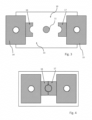
- Fig. 1 shows (in a schematic horizontal section) a press device comprising an upper punch 11, an (optional) lower punch 12, a die 13, a first filler 14 (filling shoe) and a second filler 15 (Filling shoe).
- a first part 16 of a sealing device 18 is attached to the first filler 14.
- a second part 17 of the sealing device 18 is attached to the second filler 15.
- the sealing device is designed in two parts in the present example (but can also have more than two parts in alternative embodiments).
- the first part 16 is movable together with the first filler 14 (along a matrix surface 19, in Fig. 1 to the left).
- the second part 17 of the sealing device 18 can also be moved (together with the second filler 15) (along the surface 19) (in Fig.
- FIG. 1 shows a state of the press device before the upper punch dips into a cavity 20 within the die 13. As soon as the upper punch 11 dips into the cavity 20 and touches the powder in this cavity 20, this leads to a possible displacement and a possible transport out of the powder from the cavity (if the sealing device 18 were not provided). The sealing device 18, however, prevents such transport out.
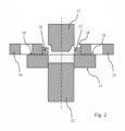
- a stepped and/or bevelled punch For example, an upper punch with a bevelled (truncated cone) end section and a step in Fig. 2 shown (in alternative embodiments, only one bevel or only one step and/or several steps and/or several bevels with different slopes can be formed).
- FIG. 3 A horizontal section of the press device according to Fig. 1 (or Fig. 2 ) is in Figures 3 and 4 shown.
- the parts 16, 17 of the sealing device 18 are removed from the cavity below the stamp 11 (and not in the sealing position). It is particularly evident that the parts 16, 17 of the sealing device 18 are attached to the respective fillers (filling shoes) 14, 15 (or are integrated into a corresponding filler structure), so that they can be moved together with the respective filler and thus into a sealing position (according to Fig. 4 ) can be brought.
- FIG. 5 a cross-section of an alternative embodiment of the sealing device 18 is shown (in a schematic horizontal section).
- engagement structures 21, 22 here, for example, in the form of sawtooth-like interlocking projections
Landscapes
- Engineering & Computer Science (AREA)
- Mechanical Engineering (AREA)
- Manufacturing & Machinery (AREA)
- Chemical & Material Sciences (AREA)
- Ceramic Engineering (AREA)
- Press-Shaping Or Shaping Using Conveyers (AREA)
Description
- Die Erfindung betrifft eine Presseneinrichtung, insbesondere Metallpulver- und/oder Keramikpulver-Presseneinrichtung, sowie ein Verfahren zum Pulverpressen eines Pulverpressteils, insbesondere Keramikpulver-Pressteils und/oder Metallpulver-Pressteils.
- Aus dem Stand der Technik sind derartige Pulver-Presseneinrichtungen (Pulverpressen) grundsätzlich bekannt. Im Stand der Technik wird ein Hohlraum (Füllraum) in einer Matrize der Presseneinrichtung befüllt. Im derartig befüllten Füllraum (Hohlraum) taucht dann ein Stempel (Oberstempel) ein, um das Pressteil zu pressen.
- Grundsätzlich sind unterschiedliche Möglichkeiten für die Befüllung des Füllraumes bekannt. Gemäß einem Standardverfahren fährt ein Füllschuh (Füllschieber) über eine offene Kavität, wobei das Pulver dann hineinrieseln kann. Eine entsprechende Füllung ist oftmals vergleichsweise unregelmäßig.
- Beim Saugfüllen kann der Füllschuh (Füllschieber bzw. Füller) über eine noch geschlossene Kavität verfahren werden. Die Matrize kann dann angehoben werden. Ein Füllraum wird dann gleichmäßiger (als im zuvor beschriebenen Standardverfahren) gefüllt.
- Beim Überfüllen kann die Matrize (zumindest etwas) höher fahren, wodurch sich eine größere Füllmenge ergibt. Vor einem Zurückfahren des Füllers (Füllschuhs bzw. Füllschiebers) kann eine tatsächlich notwendige Matrizenhöhe bzw. Einfüllhöhe eingestellt werden. Überschüssiges Pulver kann ggf. vom Füllschuh abgestreift werden.
- Beim Unterfüllen kann nach einem erfolgten Füllen die Matrize angehoben werden, so dass vorhandenes Pulver tiefer in die Matrize sinkt. Hierbei kann die Matrize verschlossen werden, bevor der Stempel das Pulver berührt. Dieses kann dann ggf. nicht entweichen. Das Dokument
DE 10 2006 051666 A1 offenbart eine Pulver-Presseinrichtung nach dem Oberbegriff des Anspruchs 1. - Insgesamt wird die Pulverbefüllung im Stand der Technik noch als verbesserungswürdig angesehen, insbesondere hinsichtlich einer möglichst genauen Einstellung derjenigen Pulvermenge, die dann letztlich auch verpresst wird.
- Es ist Aufgabe der Erfindung, eine Pulver-Presseneinrichtung, insbesondere Metallpulver- und/oder Keramikpulver-Presseneinrichtung vorzuschlagen, wobei die Befüllung mit Pulver, insbesondere auch bei sich verjüngenden und/oder gestuften Stempel-Geometrien (Oberstempel-Geometrien), vergleichsweise präzise, insbesondere zumindest im Wesentlichen ohne Verlust von Pulver oder zumindest mit nur vergleichsweise geringem Verlust von Pulver, vorzuschlagen. Weiterhin ist es Aufgabe der Erfindung, ein entsprechendes Verfahren vorzuschlagen.
- Diese Aufgabe wird insbesondere durch die Merkmale des Anspruches 1 gelöst. Insbesondere wird die Aufgabe gelöst durch eine Pulver-Presseinrichtung (Pulverpresse), insbesondere Metallpulver- und/oder Keramikpulver-Presseneinrichtung (Metallpulver- und/oder Keramikpulver-Presse), umfassend mindestens eine Matrize, mindestens einen ersten Stempel (Oberstempel), der in einer Pressstellung von einer ersten oberen Seite aus in einen mit Pulver (Keramik- und/oder Metallpulver) befüllten Hohlraum (Matrizenöffnung bzw. Kavität bzw. Füllraum) der Matrize eintauchbar angeordnet ist, sowie mindestens eine zumindest abschnittsweise (vorzugsweise vollständig) um einen oberen Rand des Hohlraums herum anordenbare, insbesondere mindestens zweiteilige, Pulver-Abdichteinrichtung.
- Ein Gedanke der Erfindung liegt darin, eine Pulver-Abdichteinrichtung vorzusehen, die derart um den Hohlraum (bzw. einen oberen Rand desselben) herum angeordnet werden kann, dass beim Eintauchen des Stempels (Oberstempels) in den Hohlraum zumindest im Wesentlichen verhindert (oder zumindest reduziert wird), dass Pulver aus dem Hohlraum herausbefördert wird (beispielsweise herausspritzt und/oder herausgedrückt wird). Dadurch kann eine präzisere Einstellung desjenigen Pulvervolumens erreicht werden, dass letztlich auch zum Pressteil verpresst wird. Weiterhin können Pulververluste reduziert werden.
- Unter einer Anordnung um den Hohlraum (bzw. einen oberen Rand desselben) herum ist insbesondere eine Anordnung zu verstehen, bei der die Pulver-Abdichteinrichtung entlang des (oberen) Randes des Hohlraumes verläuft. Zumindest in einer Stellung (beispielsweise einer Anfangsstellung, wenn ein sich verjüngender Endabschnitt des Stempels bzw. ein Endabschnitt mit vergleichsweise geringem Durchmesser in den Hohlraum eintaucht) kann die Pulver-Abdichteinrichtung auch mit einer Querschnittsfläche des Hohlraums (auf Ebene einer oberen Matrizenfläche) überlappen (in einer Projektion der Abdichteinrichtung auf diese Ebene). In konkreten Ausführungsformen ist die Abdichteinrichtung so angeordnet, dass sie (zumindest in jeglicher Abdichtstellung) außerhalb dieser Querschnittsfläche des Hohlraumes liegt (sich jedoch vorzugsweise unmittelbar, ggf. abgesehen von einem geringeren Abstand zur Ausbildung eines Spaltes gegenüber dem Stempel, an diesen anschließt).
- In weiteren Ausführungsformen ist dies zumindest in einer (Abdicht-) Position der Abdichteinrichtung, insbesondere in einer Endposition (bei der der Stempel seinen maximalen Weg in den Hohlraum hinein durchgeführt hat), der Fall.
- Unter einer zumindest abschnittsweisen (teilweisen) Anordnung um den Hohlraum herum ist insbesondere eine Anordnung zu verstehen, bei der die Abdichteinrichtung den Rand des Hohlraumes über einen Winkelbereich von mindestens 180°, vorzugsweise mindestens 270°, noch weiter vorzugsweise mindestens 350°, ggf. mindestens 359° oder 360° umgibt (bzw. entlang desselben angeordnet ist).
- Die Pulver-Abdichteinrichtung ist vorzugsweise verstellbar. Wenn die Pulver-Abdichteinrichtung zwei- oder mehrteilig ausgebildet ist, können sich diese zwei oder mehr Teile der Pulver-Abdichteinrichtung vorzugsweise relativ zueinander (insbesondere in Richtung einer oberen Matrizenoberfläche) bewegen. Die zwei oder mehr Teile können sich vorzugsweise vollständig voneinander trennen (so dass sie nicht mehr verbunden sind). Gegebenenfalls wäre es auch vorstellbar, dass die zwei oder mehr Teile sich durch eine (eine Abstandsänderung zur Relativbewegung zulassende) Verbindungs- und/oder Kopplungseinrichtung miteinander (zumindest über einen bestimmten Bereich einer Relativbewegung) verbunden sind.
- Vorzugsweise ist die Abdichteinrichtung (zumindest teilweise, bei zwei oder mehr Teilen gilt dies vorzugsweise für mehrere oder alle dieser mehreren Teile) quer zu einer Bewegungsrichtung des Stempels bewegbar (bei mehreren Teilen gilt dies insbesondere auch für eine Relativ-Bewegung der einzelnen Teile zueinander), vorzugsweise entlang einer an den Hohlraum der Matrize angrenzenden Oberfläche. Besonders bevorzugt ist die Abdichteinrichtung (bzw. deren Teile) verschiebbar, insbesondere so, dass sie bei der Bewegung bzw. Verstellung entlang einer an den Hohlraum angrenzenden Oberfläche der Matrize bewegt wird (gleitet). Auf diese Art und Weise kann besonders einfach eine präzise Positionierung der Abdichteinrichtung erfolgen, dass diese ihre Abdichtfunktion realisieren kann.
- Die Abdichteinrichtung kann während einer Bewegung des Oberstempels (bzw. dessen distalen Endes) innerhalb des Hohlraums am selben Ort verbleiben (oder in denkbaren alternativen Ausführungsformen währenddessen bewegt werden).
- Unter einer Bewegung quer zu einer Bewegungsrichtung des Stempels ist insbesondere zu verstehen, dass die Abdichteinrichtung in einem 90°-Winkel (ggf. ausschließlich in einem solchen) gegenüber der Bewegungsrichtung des Stempels (von oben nach unten) bewegbar ist. Denkbar wäre jedoch auch, dass die Bewegung in einem Winkel erfolgt, der mindestens 10° oder mindestens 30° oder mindestens 60° oder höchstens 90° oder höchstens 80° gegenüber der Bewegungsrichtung des Stempels beträgt. Es ist auch denkbar, dass sich die Bewegbarkeit der Abdichteinrichtung bzw. deren konkrete Bewegung während des Verbringens in eine abdichtende Stellung ändert.
- Im Allgemeinen kann die Abdichteinrichtung auch durch Verschwenken derselben oder von Teilen derselben (ggf. relativ zueinander) erfolgen. Noch allgemeiner kann die Abdichteinrichtung rein translatorisch oder rein rotatorisch oder sowohl translatorisch als auch rotatorisch bewegt werden, um sie in eine abdichtende Position zu verbringen (dies kann auch für mehrere oder alle von ggf. mehreren gegeneinander beweglichen Teilen der Abdichteinrichtung gelten).
- In einer konkreten Ausführungsform ist mindestens ein Teil der Abdichteinrichtung an einem Füllschuh (Füller) angeordnet oder anordenbar, beispielsweise als integraler Teil desselben ausgebildet oder an diesem angebracht oder anbringbar. Vorzugsweise ist ein erstes Teil der Abdichteinrichtung an einem ersten Füllschuh (Füller) angeordnet oder anordenbar, beispielsweise als integraler Bestandteil desselben ausgebildet oder an diesen angebracht oder anbringbar, und ein zweites Teil der Abdichteinrichtung an einem zweiten Füllschuh (Füller) angeordnet oder anordenbar, beispielsweise als integraler Bestandteil desselben ausgebildet oder an diesen angebracht oder anbringbar.
- Konkret kann die Abdichteinrichtung bzw. das (jeweilige) erste bzw. zweite Teil an den (jeweiligen) Füllschuh angeschraubt und/oder angeschweißt und/oder per Klemm- und/oder Spanneinrichtung und/oder auf noch andere Art und Weise angebracht sein bzw. werden. Bei einer derartigen Integration in eine Füllschuhstruktur kann der entsprechende Füllschuh (bzw. die Gesamtstruktur, umfassend die Abdichteinrichtung oder deren erstes/zweites/weiteres Teil) auf einfache Art und Weise eine doppelte Funktion erfüllen, nämlich einerseits überhaupt das Pulver in Richtung Hohlraum (Kavität) zu befördern, um das Pulver in die Kavität zu bringen, einerseits, und, andererseits, um eine Abdichtung zu realisieren. Besonders bevorzugt kann dieselbe Antriebseinrichtung benutzt werden, um sowohl die Bewegung des Füllschuhs zum Befüllen des Hohlraums als auch die Bewegung des Füllschuhs (bzw. der Struktur mit der Abdichteinrichtung bzw. dem Teil derselben) zur Abdichtung zu realisieren.
- Ein distales Endes des Stempels (Oberstempels) ist vorzugsweise so ausgebildet, dass eine Projektion eines Querschnittes dieses distalen Endes auf eine Ebene der (oberen) Oberfläche der Matrize bzw. eines oberen Querschnittes des Hohlraumes zumindest teilweise von einem Rand des Hohlraumes beabstandet ist. Die Beabstandung von dem Rand des Hohlraumes kann beispielsweise mindestens 0,1 mm oder mindestens 0,5 mm oder mindestens 1,0 mm und/oder höchstens 1,0 cm betragen (über zumindest einen Winkelbereich von 180° des Randes, ggf. den gesamten Rand). Bei einer derartigen Ausführungsform würde ein Einführen des (Ober-) Stempels in den Pulver-gefüllten Hohlraum - ohne die erfindungsgemäße Abdichteinrichtung - in besonders ausgeprägtem Maße dazu führen, dass Pulver aus dem Hohlraum herausgedrückt würde (bzw. herausspritzen würde). Dies wird durch die Abdichteinrichtung auf vorteilhafte Art und Weise verhindert oder zumindest reduziert.
- In einer konkreten Ausführungsform verjüngt sich der (Ober-) Stempel zumindest abschnittsweise in Richtung seines distalen Endes. Der Stempel kann abgeschrägt sein und/oder eine Stufe aufweisen und/oder zumindest abschnittsweise (in mindestens einem Längsschnitt; beispielsweise in einem Übergang zwischen zwei Oberstempelabschnitten) mindestens eine Rundung und/oder Bogenform aufweisen, z. B. abgerundet und/oder ausgerundet sein.. Unter einer Abschrägung ist vorzugsweise eine zumindest abschnittsweise plane und/oder kegelstumpfförmige Abschrägung zu verstehen. In Ausführungsformen kann ein distaler Endabschnitt des Stempels durch einen Kegel oder Kegelstumpfabschnitt gebildet werden. Denkbar ist, dass ein distaler Endabschnitt des Stempels durch einen (beispielsweise geraden), insbesondere kreisförmigen, Zylinder ausgebildet wird, an dem sich ein weiterer Abschnitt des Stempels anschließt (beispielsweise ein weiterer Zylinder, insbesondere Kreiszylinder), der einen größeren Durchmesser aufweist (wobei ein Übergang zwischen den Abschnitten ausgerundet sein kann).
- Die Abdichteinrichtung kann so um den Stempel herum angeordnet sein bzw. werden, dass zwischen Abdichteinrichtung und Stempel zumindest abschnittsweise (z. B. über einen Winkelberiech von mindestens 180° oder mindestens 270° oder mindestens 350° oder 360°) ein Abstand, insbesondere in Form eines, ggf. umlaufenden, Spalts ausgebildet wird, derart, dass Luft aus dem Hohlraum (der Kavität) entweichen kann. Der Abstand beträgt vorzugsweise mindestens 10 Mikrometer und/oder höchstens 500 Mikrometer oder höchstens 300 Mikrometer oder höchstens 100 Mikrometer. Durch einen derartigen Abstand (Spalt) kann trotz Abdichteinrichtung Luft aus dem Hohlraum entweichen, so dass es hier nicht zu (ungewünschter) Luftkomprimierung kommt.
- Vorzugsweise liegt die Abdichteinrichtung (im abdichtenden Zustand) dicht an einer dem Hohlraum umgebenden Oberfläche (oberen Oberfläche der Matrize) an. Insbesondere ist die Abdichteinrichtung an ihrer Unterseite plan, wobei diese plane Unterseite (dicht) an der (oberen) Oberfläche der Matrize anliegt bzw. anliegen kann.
- Die Abdichteinrichtung kann mindestens zwei gegeneinander verstellbare (insbesondere sich ggf. stumpf berührende) Segmente (Teile) aufweisen, die vorzugsweise im abdichtenden Zustand der Abdichteinrichtung miteinander in Eingriff stehen, insbesondere über mindestens einen Vorsprung, der mit mindestens einer Ausnehmung in Eingriff steht. Eine Ineingriffnahme kann vorzugsweise über eine zickzackförmige Struktur bzw. Sägezahnstruktur erfolgen und/oder über eine Nut-Feder-Verbindung. Die Ineingriffnahme erfolgt vorzugsweise so, dass die beiden Segmente so miteinander verbunden sind, dass die Ineingriffnahme einer (in Richtung einer Verbindungsebene weisenden) Kraft, insbesondere von innen nach außen, entgegenwirkt.
- In verschiedenen Ausführungsformen kann die Abdichteinrichtung mindestens oder genau zwei oder mindestens oder genau drei oder mindestens oder genau vier gegeneinander verstellbare Segmente (Teile) aufweisen. Wenn die Abdichteinrichtung mehrere Segmente (Teile) aufweist, können diese vorzugsweise unabhängig von den jeweils anderen Segmenten (Teilen) verstellt werden. Alternativ ist es auch möglich, dass nur eine gemeinsame (ggf. synchronisierte) Verstellung möglich ist oder zumindest einstellbar ist.
- Die oben genannte Aufgabe wird weiterhin insbesondere gelöst durch ein Verfahren zum Pulverpressen eines Pulverpressteils, insbesondere Keramikpulver-Pressteils und/oder Metallpulver-Pressteils, unter Verwendung der obigen Presseneinrichtung. In dem Verfahren wird vorzugsweise Pulver in eine Kavität der Matrize gefüllt, die Abdichtungseinrichtung um eine Matrizenöffnung herum angeordnet und (daraufhin) der Stempel (Oberstempel) zum Pressen in die Kavität (den Hohlraum) eingetaucht. Weitere Verfahrensmerkmale ergeben sich aus der obigen und/oder nachfolgenden Beschreibung der Presseneinrichtung. Funktionale Merkmale der Presseneinrichtung (bzw. entsprechende Konfigurationen derselben) können als konkrete Verfahrensschritte durchgeführt werden. Wenn beispielsweise weiter oben und/oder nachfolgend offenbart ist, dass ein Teil der Presseneinrichtung anordenbar bzw. verstellbar ist, soll dies für das Verfahren insbesondere bedeuten, dass eine entsprechende Anordnung (als Schritt, insbesondere umfassend eine Positionsänderung) erfolgen kann bzw. ein entsprechender Schritt zur Verstellung durchgeführt wird.
- Die obengenannte Aufgabe wird insbesondere weiterhin gelöst durch die Verwendung einer Presseneinrichtung der obigen Art zum Pulverpressen eines Pulverpressteils, insbesondere zum Pressen eines Keramikpulver-Pressteils und/oder Metallpulver-Pressteils.
- Die Presseneinrichtung kann in Ausführungsformen eine Presskraft von mindestens 1,0 Tonnen oder mindestens 10 Tonnen oder mindestens 100 Tonnen und/oder höchstens 1000 Tonnen erzeugen.
- Weitere Ausführungsformen ergeben sich aus den Unteransprüchen.
- Nachfolgend wird die Erfindung anhand von Ausführungsbeispielen beschrieben, die anhand der Abbildungen näher erläutert werden. Hierbei zeigen:
- Fig. 1
- eine erfindungsgemäße Presseneinrichtung in einem schematischen Schnitt (Querschnitt bzw. Vertikalschnitt);
- Fig. 2
- eine alternative Ausführungsform in einem Schnitt analog
Fig. 1 ; - Fig. 3
- die Presseneinrichtung gemäß
Fig. 1 in einem schematischen Horizontalschnitt in einer ersten Stellung; - Fig. 4
- die Presseneinrichtung gemäß
Fig. 1 in einem schematischen Horizontalschnitt in einer zweiten Stellung; und - Fig. 5
- eine alternative Ausführungsform in einem Horizontalschnitt.
- In der nachfolgenden Beschreibung werden für gleiche und gleich wirkende Teile dieselben Bezugsziffern verwendet.
-
Fig. 1 zeigt (in einem schematischen Horizontalschnitt) eine Presseneinrichtung umfassend einen Oberstempel 11, einen (optionalen) Unterstempel 12, eine Matrize 13, einen ersten Füller 14 (Füllschuh) sowie einen zweiten Füller 15 (Füllschuh). An den ersten Füller 14 ist ein erstes Teil 16 einer Abdichteinrichtung 18 angebracht. An dem zweiten Füller 15 ist ein zweites Teil 17 der Abdichteinrichtung 18 angebracht. Die Abdichteinrichtung ist im vorliegenden Beispiel zweiteilig ausgebildet (kann jedoch in alternativen Ausführungsformen auch mehr als zwei Teile aufweisen). Insbesondere ist das erste Teil 16 gemeinsam mit dem ersten Füller 14 bewegbar (entlang einer Matrizenoberfläche 19, inFig. 1 nach links). Das zweite Teil 17 der Abdichteinrichtung 18 kann (gemeinsam mit dem zweiten Füller 15) ebenfalls (entlang der Oberfläche 19) bewegt werden (inFig. 1 nach rechts).Fig. 1 zeigt einen Zustand der Presseneinrichtung, bevor der Oberstempel in einen Hohlraum 20 innerhalb der Matrize 13 eintaucht. Sobald der Oberstempel 11 in den Hohlraum 20 eintaucht und das Pulver in diesem Hohlraum 20 berührt, führt dies zu einer möglichen Verdrängung und einem möglichen Herausbefördern des Pulvers aus dem Hohlraum (wenn die Abdichteinrichtung 18 nicht vorgesehen wäre). Die Abdichteinrichtung 18 verhindert jedoch ein solches Herausbefördern. - Dies ist besonders ausgeprägt bei einem gestuften und/oder abgeschrägten Stempel. Beispielsweise ist ein Oberstempel mit einem abgeschrägten (kegelstumpfförmigen) Endabschnitt sowie einer Stufe in
Fig. 2 gezeigt (in alternativen Ausführungsformen können auch nur eine Abschrägung oder nur eine Stufe und/oder mehrere Stufen und/oder mehrere Abschrägungen mit unterschiedlicher Steigung ausgebildet sein). - Ein Horizontalschnitt der Presseneinrichtung gemäß
Fig. 1 (oder auchFig. 2 ) ist inFiguren 3 und 4 gezeigt. InFigur 3 sind die Teile 16, 17 der Abdichteinrichtung 18 von dem Hohlraum unterhalb des Stempel 11 entfernt (und nicht in AbdichtStellung). Es ist insbesondere erkennbar, dass die Teile 16, 17 der Abdichteinrichtung 18 an die jeweiligen Füller (Füllschuhe) 14, 15 angebracht sind (bzw. in eine entsprechende Füllerstruktur integriert sind), so dass diese gemeinsam mit dem jeweiligen Füller bewegbar sind und damit in eine abdichtende Position (gemäßFig. 4 ) gebracht werden können. - Denkbar ist auch eine von einem (regulären) Füllschuh getrennte Ausführung der Füllraumabdichtung. Diese kann z.B. von einem elektrischen, hydraulischen und/oder pneumatischen Antrieb parallel zum originären Füllschuh und/oder in der Ebene beliebig verdreht einfahrbar sein.
- Alternativ oder zusätzlich ist auch ein Einschwenken der Einrichtung, z. B. mit einem entsprechenden Drehantrieb, denkbar.
- In
Fig. 5 ist ein Querschnitt einer alternativen Ausführungsform der Abdichteinrichtung 18 (in einem schematischen Horizontalschnitt) gezeigt. Insbesondere sind hier Eingriffsstrukturen 21, 22 (hier beispielhaft in Form von insbesondere sägezahnartig-ineinandergreifenden Vorsprüngen) erkennbar, die die einzelnen Teile 16, 17 der Abdichteinrichtung 18 miteinander in Eingriff bringen. -
- 11
- Oberstempel
- 12
- Unterstempel
- 13
- Matrize
- 14
- Füller (Füllschuh)
- 15
- Füller (Füllschuh)
- 16
- erstes Teil
- 17
- zweites Teil
- 18
- Abdichteinrichtung
- 19
- Oberfläche
- 20
- Hohlraum
- 21
- Eingriffsstruktur
- 22
- Eingriffsstruktur
Claims (12)
- Pulver-Presseneinrichtung, insbesondere Metallpulver- und/oder Keramikpulver-Presseneinrichtung, umfassend mindestens eine Matrize (13), mindestens einen ersten Stempel (11), der in einer Pressstellung von einer ersten oberen Seite aus in einen mit Pulver befüllten Hohlraum (20) der Matrize (13) eintauchbar angeordnet ist,
dadurch gekennzeichnet, dass
die Pulver-Presseinrichtung mindestens eine zumindest abschnittsweise, vorzugsweise vollständig, um einen oberen Rand des Hohlraums (20) herum in der Pressstellung anordenbare, mindestens zweiteilige, Pulver-Abdichteinrichtung (18) umfasst. - Presseneinrichtung nach Anspruch 1,
dadurch gekennzeichnet, dass
die Abdichteinrichtung (18) zumindest teilweise quer zu einer Bewegungsrichtung des Stempels bewegbar ist, vorzugsweise entlang einer an den Hohlraum (20) der Matrize (13) angrenzenden Oberfläche (19) bewegbar ist. - Presseneinrichtung nach einem der vorangehenden Ansprüche,
dadurch gekennzeichnet, dass
mindestens ein Teil der Abdichteinrichtung (18) an einem Füllschuh angeordnet oder anordenbar ist, beispielsweise als integraler Bestandteil desselben ausgebildet ist oder an diesen angebracht oder anbringbar ist, vorzugsweise ein erstes Teil (16) der Abdichteinrichtung (18) an einem ersten Füllschuh angeordnet oder anordenbar ist, beispielsweise als integraler Bestandteil desselben ausgebildet ist oder an diesen angebracht oder anbringbar ist, und ein zweites Teil (17) der Abdichteinrichtung (18) an einem zweiten Füllschuh angeordnet oder anordenbar ist, beispielsweise als integraler Bestandteil desselben ausgebildet ist oder an diesen angebracht oder anbringbar ist. - Presseneinrichtung nach einem der vorhergehenden Ansprüche,
dadurch gekennzeichnet, dass
eine Projektion eines Querschnittes eines distalen Endes des Stempels auf eine Ebene der oberen Oberfläche (19) der Matrize (13) zumindest teilweise von einem Rand des Hohlraums beabstandet ist. - Presseneinrichtung nach einem der vorhergehenden Ansprüche,
dadurch gekennzeichnet, dass
sich der Stempel (11) zumindest abschnittsweise in Richtung seines distalen Endes verjüngt, insbesondere abgeschrägt ist und/oder eine Stufe aufweist. - Presseneinrichtung nach einem der vorhergehenden Ansprüche,
dadurch gekennzeichnet, dass
die Abdichteinrichtung (18) so um den Stempel (11) herum anordenbar ist, dass zwischen Abdichteinrichtung (18) und Stempel (11) zumindest abschnittsweise ein Abstand, insbesondere in Form eines, ggf. umlaufenden, Spaltes ausgebildet ist, derart, dass Luft aus dem Hohlraum (20) entweichen kann, wobei der Abstand vorzugsweise mindestens 10 Mikrometer und/oder höchstens 100 Mikrometer beträgt. - Presseneinrichtung nach einem der vorhergehenden Ansprüche,
dadurch gekennzeichnet, dass
die Abdichteinrichtung (18) im abdichtenden Zustand dicht an einer den Hohlraum (20) umgebenden Oberfläche (19) der Matrize (13) anliegt. - Presseneinrichtung nach einem der vorhergehenden Ansprüche,
dadurch gekennzeichnet, dass
die Abdichteinrichtung (18) mindestens zwei gegeneinander verstellbare Segmente aufweist, die vorzugsweise im abdichtenden Zustand der Abdichteinrichtung (18) miteinander in Eingriff stehen, insbesondere über mindestens einen Vorsprung, der mit mindestens einer Ausnehmung und/oder mindestens einem korrespondieren Vorsprung in Eingriff steht. - Presseneinrichtung nach einem der vorhergehenden Ansprüche,
dadurch gekennzeichnet, dass
die Abdichteinrichtung (18) mindestens oder genau zwei oder mindestens oder genau drei oder mindestens oder genau vier gegeneinander verstellbare Segmente aufweist. - Verfahren zum Pulverpressen eines Pulverpressteils, insbesondere Keramikpulver-Pressteils und/oder Metallpulver-Pressteils, unter Verwendung einer Presseneinrichtung nach einem der vorhergehenden Ansprüche.
- Verfahren nach Anspruch 10,
dadurch gekennzeichnet, dass
Pulver in eine Kavität der Matrize (13) gefüllt wird, die Abdichteinrichtung (18) um eine Matrizenöffnung herum angeordnet wird und der Stempel (11) zum Pressen in den Hohlraum (20) eintaucht. - Verwendung einer Presseneinrichtung nach einem der Ansprüche 1 bis 9 zum Pulverpressen eines Pulverpressteils, insbesondere zum Pressen eines Keramikpulver-Pressteils und/oder Metallpulver-Pressteils.
Applications Claiming Priority (1)
| Application Number | Priority Date | Filing Date | Title |
|---|---|---|---|
| DE102021105649.7A DE102021105649A1 (de) | 2021-03-09 | 2021-03-09 | Presseneinrichtung |
Publications (2)
| Publication Number | Publication Date |
|---|---|
| EP4056359A1 EP4056359A1 (de) | 2022-09-14 |
| EP4056359B1 true EP4056359B1 (de) | 2024-11-06 |
Family
ID=80684109
Family Applications (1)
| Application Number | Title | Priority Date | Filing Date |
|---|---|---|---|
| EP22160958.9A Active EP4056359B1 (de) | 2021-03-09 | 2022-03-09 | Presseneinrichtung |
Country Status (3)
| Country | Link |
|---|---|
| US (1) | US20220288682A1 (de) |
| EP (1) | EP4056359B1 (de) |
| DE (1) | DE102021105649A1 (de) |
Family Cites Families (9)
| Publication number | Priority date | Publication date | Assignee | Title |
|---|---|---|---|---|
| US2598016A (en) * | 1950-04-17 | 1952-05-27 | Hpm Dev Corp | Apparatus for hot pressing powdered metals |
| US4544517A (en) * | 1981-12-16 | 1985-10-01 | General Electric Co. | Automatic composite press technique for producing cutting inserts |
| DE69127557T2 (de) * | 1990-11-30 | 1998-01-08 | Intermetallics Co Ltd | Verfahren zur Herstellung eines Permanentmagneten und Vorrichtung zur Herstellung eines Grünlings |
| US5897826A (en) | 1996-06-14 | 1999-04-27 | Materials Innovation, Inc. | Pulsed pressurized powder feed system and method for uniform particulate material delivery |
| DE102006051666A1 (de) * | 2006-11-02 | 2008-05-08 | Dorst Technologies Gmbh & Co. Kg | Vorrichtung zum Pressen von Pressteilen mit einer Pressgut-Zuführungseinrichtung |
| DE102008044687A1 (de) | 2007-10-27 | 2009-04-30 | Joint Solar Silicon Gmbh & Co. Kg | Aufbereitung von Formlingen aus Reinstsilizium |
| JP5036064B2 (ja) * | 2008-06-27 | 2012-09-26 | 日立粉末冶金株式会社 | 偏肉形状部品の圧粉体成形方法および圧粉体成形金型装置 |
| US7850884B2 (en) | 2009-04-01 | 2010-12-14 | The Gillette Company | Method of compacting material |
| JP6454697B2 (ja) * | 2013-07-05 | 2019-01-16 | サンドビック インテレクチュアル プロパティー アクティエボラーグ | 切削インサート成形体を製造するための方法及び装置 |
-
2021
- 2021-03-09 DE DE102021105649.7A patent/DE102021105649A1/de active Pending
-
2022
- 2022-03-09 US US17/654,162 patent/US20220288682A1/en active Pending
- 2022-03-09 EP EP22160958.9A patent/EP4056359B1/de active Active
Also Published As
| Publication number | Publication date |
|---|---|
| DE102021105649A1 (de) | 2022-09-15 |
| US20220288682A1 (en) | 2022-09-15 |
| EP4056359A1 (de) | 2022-09-14 |
Similar Documents
| Publication | Publication Date | Title |
|---|---|---|
| EP3426423B1 (de) | Vorrichtung zur herstellung von gussteilen, wie aluminiumguss, im druckverfahren oder niederdruckverfahren | |
| DE2538139A1 (de) | Schraube | |
| DE2142570B2 (de) | Mechanische Pulverpresse, insbesondere Metallpulverpresse | |
| EP3107672A1 (de) | Formwerkzeug, verfahren zur herstellung eines grünlings und verwendung des formwerkzeugs | |
| EP3253567A1 (de) | Pulverpresse mit kegeligem unterbau | |
| EP0542144B1 (de) | Vorrichtung zum Verbinden eines Drahtes mit einem Stecker, Kontaktelement od.dgl. | |
| DE1475265A1 (de) | Befestigungsvorrichtung und Verfahren und Einrichtung zu ihrer Herstellung | |
| EP4076881B1 (de) | Vorrichtung zur herstellung von betonsteinen | |
| DE102011089682B4 (de) | Matrize für eine Stanzvorrichtung, Stanzwerkzeug für eine Stanzvor-richtung mit einer solchen Matrize sowie Verfahren zum Heraus-schneiden von Werkstückteilen aus Werkstücken mit einer entspre-chenden Matrize | |
| DE202017107149U1 (de) | Crackspalt-Formwerkzeug zum Herstellen eines Partikelschaumstoffteils sowie Vorrichtung zum Herstellen eines Partikelschaumstoffteils | |
| WO1984004127A1 (en) | Self propelled scaffold for buildings, cable tensioner and method for building and/or maintaining high buildings | |
| DE3418981A1 (de) | Stempel-gesenk-anordnung fuer eine pulververdichterpresse | |
| EP4056359B1 (de) | Presseneinrichtung | |
| DE2706817A1 (de) | Blechstreifen-aushebeeinrichtung fuer folgeschnitt-stanz- und praegewerkzeuge | |
| DE60106191T2 (de) | Vorrichtung zum Anpressen von Kabelendklemmen | |
| DE2350810A1 (de) | Vorrichtung zur herstellung von behaeltern | |
| DE4417663C2 (de) | Preßteil aus Metallpulver, Verfahren und Vorrichtung zu seiner Herstellung | |
| EP0266625B1 (de) | Oberer Werkzeugträger für eine Stanze od. dgl. | |
| DE3327801A1 (de) | Vorrichtung und verfahren zum verdichten von pulvermaterial | |
| EP1526932B1 (de) | Verfahren sowie matrize zur anbringung eines funktionselements an ein blechteil | |
| DE2357309C3 (de) | ||
| DE3304075C2 (de) | ||
| DE10035427A1 (de) | Vorrichtung zum Eindrücken von Schrauben | |
| EP2996864B1 (de) | Verfahren und vorrichtung zum aufbringen von zierstreifen auf einen sitzbezug | |
| EP3815844B1 (de) | Spannbackenanordnung |
Legal Events
| Date | Code | Title | Description |
|---|---|---|---|
| PUAI | Public reference made under article 153(3) epc to a published international application that has entered the european phase |
Free format text: ORIGINAL CODE: 0009012 |
|
| STAA | Information on the status of an ep patent application or granted ep patent |
Free format text: STATUS: THE APPLICATION HAS BEEN PUBLISHED |
|
| AK | Designated contracting states |
Kind code of ref document: A1 Designated state(s): AL AT BE BG CH CY CZ DE DK EE ES FI FR GB GR HR HU IE IS IT LI LT LU LV MC MK MT NL NO PL PT RO RS SE SI SK SM TR |
|
| STAA | Information on the status of an ep patent application or granted ep patent |
Free format text: STATUS: REQUEST FOR EXAMINATION WAS MADE |
|
| 17P | Request for examination filed |
Effective date: 20230314 |
|
| RBV | Designated contracting states (corrected) |
Designated state(s): AL AT BE BG CH CY CZ DE DK EE ES FI FR GB GR HR HU IE IS IT LI LT LU LV MC MK MT NL NO PL PT RO RS SE SI SK SM TR |
|
| RIC1 | Information provided on ipc code assigned before grant |
Ipc: B30B 11/02 20060101ALI20231023BHEP Ipc: B30B 15/30 20060101AFI20231023BHEP |
|
| GRAP | Despatch of communication of intention to grant a patent |
Free format text: ORIGINAL CODE: EPIDOSNIGR1 |
|
| STAA | Information on the status of an ep patent application or granted ep patent |
Free format text: STATUS: GRANT OF PATENT IS INTENDED |
|
| INTG | Intention to grant announced |
Effective date: 20231207 |
|
| GRAJ | Information related to disapproval of communication of intention to grant by the applicant or resumption of examination proceedings by the epo deleted |
Free format text: ORIGINAL CODE: EPIDOSDIGR1 |
|
| STAA | Information on the status of an ep patent application or granted ep patent |
Free format text: STATUS: REQUEST FOR EXAMINATION WAS MADE |
|
| INTC | Intention to grant announced (deleted) | ||
| GRAP | Despatch of communication of intention to grant a patent |
Free format text: ORIGINAL CODE: EPIDOSNIGR1 |
|
| STAA | Information on the status of an ep patent application or granted ep patent |
Free format text: STATUS: GRANT OF PATENT IS INTENDED |
|
| INTG | Intention to grant announced |
Effective date: 20240517 |
|
| GRAS | Grant fee paid |
Free format text: ORIGINAL CODE: EPIDOSNIGR3 |
|
| GRAA | (expected) grant |
Free format text: ORIGINAL CODE: 0009210 |
|
| STAA | Information on the status of an ep patent application or granted ep patent |
Free format text: STATUS: THE PATENT HAS BEEN GRANTED |
|
| AK | Designated contracting states |
Kind code of ref document: B1 Designated state(s): AL AT BE BG CH CY CZ DE DK EE ES FI FR GB GR HR HU IE IS IT LI LT LU LV MC MK MT NL NO PL PT RO RS SE SI SK SM TR |
|
| REG | Reference to a national code |
Ref country code: GB Ref legal event code: FG4D Free format text: NOT ENGLISH |
|
| REG | Reference to a national code |
Ref country code: CH Ref legal event code: EP |
|
| REG | Reference to a national code |
Ref country code: DE Ref legal event code: R096 Ref document number: 502022002045 Country of ref document: DE |
|
| REG | Reference to a national code |
Ref country code: IE Ref legal event code: FG4D Free format text: LANGUAGE OF EP DOCUMENT: GERMAN |
|
| REG | Reference to a national code |
Ref country code: LT Ref legal event code: MG9D |
|
| REG | Reference to a national code |
Ref country code: NL Ref legal event code: MP Effective date: 20241106 |
|
| PG25 | Lapsed in a contracting state [announced via postgrant information from national office to epo] |
Ref country code: IS Free format text: LAPSE BECAUSE OF FAILURE TO SUBMIT A TRANSLATION OF THE DESCRIPTION OR TO PAY THE FEE WITHIN THE PRESCRIBED TIME-LIMIT Effective date: 20250306 Ref country code: HR Free format text: LAPSE BECAUSE OF FAILURE TO SUBMIT A TRANSLATION OF THE DESCRIPTION OR TO PAY THE FEE WITHIN THE PRESCRIBED TIME-LIMIT Effective date: 20241106 Ref country code: PT Free format text: LAPSE BECAUSE OF FAILURE TO SUBMIT A TRANSLATION OF THE DESCRIPTION OR TO PAY THE FEE WITHIN THE PRESCRIBED TIME-LIMIT Effective date: 20250306 |
|
| PG25 | Lapsed in a contracting state [announced via postgrant information from national office to epo] |
Ref country code: FI Free format text: LAPSE BECAUSE OF FAILURE TO SUBMIT A TRANSLATION OF THE DESCRIPTION OR TO PAY THE FEE WITHIN THE PRESCRIBED TIME-LIMIT Effective date: 20241106 Ref country code: NL Free format text: LAPSE BECAUSE OF FAILURE TO SUBMIT A TRANSLATION OF THE DESCRIPTION OR TO PAY THE FEE WITHIN THE PRESCRIBED TIME-LIMIT Effective date: 20241106 |
|
| PG25 | Lapsed in a contracting state [announced via postgrant information from national office to epo] |
Ref country code: BG Free format text: LAPSE BECAUSE OF FAILURE TO SUBMIT A TRANSLATION OF THE DESCRIPTION OR TO PAY THE FEE WITHIN THE PRESCRIBED TIME-LIMIT Effective date: 20241106 |
|
| PG25 | Lapsed in a contracting state [announced via postgrant information from national office to epo] |
Ref country code: ES Free format text: LAPSE BECAUSE OF FAILURE TO SUBMIT A TRANSLATION OF THE DESCRIPTION OR TO PAY THE FEE WITHIN THE PRESCRIBED TIME-LIMIT Effective date: 20241106 |
|
| PG25 | Lapsed in a contracting state [announced via postgrant information from national office to epo] |
Ref country code: NO Free format text: LAPSE BECAUSE OF FAILURE TO SUBMIT A TRANSLATION OF THE DESCRIPTION OR TO PAY THE FEE WITHIN THE PRESCRIBED TIME-LIMIT Effective date: 20250206 |
|
| PG25 | Lapsed in a contracting state [announced via postgrant information from national office to epo] |
Ref country code: GR Free format text: LAPSE BECAUSE OF FAILURE TO SUBMIT A TRANSLATION OF THE DESCRIPTION OR TO PAY THE FEE WITHIN THE PRESCRIBED TIME-LIMIT Effective date: 20250207 Ref country code: LV Free format text: LAPSE BECAUSE OF FAILURE TO SUBMIT A TRANSLATION OF THE DESCRIPTION OR TO PAY THE FEE WITHIN THE PRESCRIBED TIME-LIMIT Effective date: 20241106 |
|
| PGFP | Annual fee paid to national office [announced via postgrant information from national office to epo] |
Ref country code: AT Payment date: 20250417 Year of fee payment: 4 |
|
| PG25 | Lapsed in a contracting state [announced via postgrant information from national office to epo] |
Ref country code: PL Free format text: LAPSE BECAUSE OF FAILURE TO SUBMIT A TRANSLATION OF THE DESCRIPTION OR TO PAY THE FEE WITHIN THE PRESCRIBED TIME-LIMIT Effective date: 20241106 |
|
| PG25 | Lapsed in a contracting state [announced via postgrant information from national office to epo] |
Ref country code: RS Free format text: LAPSE BECAUSE OF FAILURE TO SUBMIT A TRANSLATION OF THE DESCRIPTION OR TO PAY THE FEE WITHIN THE PRESCRIBED TIME-LIMIT Effective date: 20250206 |
|
| PG25 | Lapsed in a contracting state [announced via postgrant information from national office to epo] |
Ref country code: SM Free format text: LAPSE BECAUSE OF FAILURE TO SUBMIT A TRANSLATION OF THE DESCRIPTION OR TO PAY THE FEE WITHIN THE PRESCRIBED TIME-LIMIT Effective date: 20241106 |
|
| PG25 | Lapsed in a contracting state [announced via postgrant information from national office to epo] |
Ref country code: DK Free format text: LAPSE BECAUSE OF FAILURE TO SUBMIT A TRANSLATION OF THE DESCRIPTION OR TO PAY THE FEE WITHIN THE PRESCRIBED TIME-LIMIT Effective date: 20241106 |
|
| PGFP | Annual fee paid to national office [announced via postgrant information from national office to epo] |
Ref country code: IT Payment date: 20250331 Year of fee payment: 4 |
|
| PG25 | Lapsed in a contracting state [announced via postgrant information from national office to epo] |
Ref country code: EE Free format text: LAPSE BECAUSE OF FAILURE TO SUBMIT A TRANSLATION OF THE DESCRIPTION OR TO PAY THE FEE WITHIN THE PRESCRIBED TIME-LIMIT Effective date: 20241106 |
|
| PG25 | Lapsed in a contracting state [announced via postgrant information from national office to epo] |
Ref country code: RO Free format text: LAPSE BECAUSE OF FAILURE TO SUBMIT A TRANSLATION OF THE DESCRIPTION OR TO PAY THE FEE WITHIN THE PRESCRIBED TIME-LIMIT Effective date: 20241106 |
|
| PG25 | Lapsed in a contracting state [announced via postgrant information from national office to epo] |
Ref country code: SK Free format text: LAPSE BECAUSE OF FAILURE TO SUBMIT A TRANSLATION OF THE DESCRIPTION OR TO PAY THE FEE WITHIN THE PRESCRIBED TIME-LIMIT Effective date: 20241106 |
|
| PG25 | Lapsed in a contracting state [announced via postgrant information from national office to epo] |
Ref country code: CZ Free format text: LAPSE BECAUSE OF FAILURE TO SUBMIT A TRANSLATION OF THE DESCRIPTION OR TO PAY THE FEE WITHIN THE PRESCRIBED TIME-LIMIT Effective date: 20241106 |
|
| REG | Reference to a national code |
Ref country code: DE Ref legal event code: R097 Ref document number: 502022002045 Country of ref document: DE |
|
| PG25 | Lapsed in a contracting state [announced via postgrant information from national office to epo] |
Ref country code: SE Free format text: LAPSE BECAUSE OF FAILURE TO SUBMIT A TRANSLATION OF THE DESCRIPTION OR TO PAY THE FEE WITHIN THE PRESCRIBED TIME-LIMIT Effective date: 20241106 |
|
| PLBE | No opposition filed within time limit |
Free format text: ORIGINAL CODE: 0009261 |
|
| STAA | Information on the status of an ep patent application or granted ep patent |
Free format text: STATUS: NO OPPOSITION FILED WITHIN TIME LIMIT |
|
| PGFP | Annual fee paid to national office [announced via postgrant information from national office to epo] |
Ref country code: LU Payment date: 20250825 Year of fee payment: 4 |
|
| PGFP | Annual fee paid to national office [announced via postgrant information from national office to epo] |
Ref country code: DE Payment date: 20250821 Year of fee payment: 4 |
|
| PG25 | Lapsed in a contracting state [announced via postgrant information from national office to epo] |
Ref country code: MC Free format text: LAPSE BECAUSE OF FAILURE TO SUBMIT A TRANSLATION OF THE DESCRIPTION OR TO PAY THE FEE WITHIN THE PRESCRIBED TIME-LIMIT Effective date: 20241106 |
|
| 26N | No opposition filed |
Effective date: 20250807 |
|
| PGFP | Annual fee paid to national office [announced via postgrant information from national office to epo] |
Ref country code: CH Payment date: 20250825 Year of fee payment: 4 |