EP4046893B1 - Kupplungsmechanismus, lenksystem und kraftfahrzeug - Google Patents
Kupplungsmechanismus, lenksystem und kraftfahrzeug Download PDFInfo
- Publication number
- EP4046893B1 EP4046893B1 EP20880207.4A EP20880207A EP4046893B1 EP 4046893 B1 EP4046893 B1 EP 4046893B1 EP 20880207 A EP20880207 A EP 20880207A EP 4046893 B1 EP4046893 B1 EP 4046893B1
- Authority
- EP
- European Patent Office
- Prior art keywords
- end shaft
- steering
- clutch mechanism
- hollow structure
- shaft
- Prior art date
- Legal status (The legal status is an assumption and is not a legal conclusion. Google has not performed a legal analysis and makes no representation as to the accuracy of the status listed.)
- Active
Links
Images


Classifications
-
- B—PERFORMING OPERATIONS; TRANSPORTING
- B62—LAND VEHICLES FOR TRAVELLING OTHERWISE THAN ON RAILS
- B62D—MOTOR VEHICLES; TRAILERS
- B62D5/00—Power-assisted or power-driven steering
- B62D5/001—Mechanical components or aspects of steer-by-wire systems, not otherwise provided for in this maingroup
- B62D5/005—Mechanical components or aspects of steer-by-wire systems, not otherwise provided for in this maingroup means for generating torque on steering wheel or input member, e.g. feedback
- B62D5/006—Mechanical components or aspects of steer-by-wire systems, not otherwise provided for in this maingroup means for generating torque on steering wheel or input member, e.g. feedback power actuated
-
- B—PERFORMING OPERATIONS; TRANSPORTING
- B62—LAND VEHICLES FOR TRAVELLING OTHERWISE THAN ON RAILS
- B62D—MOTOR VEHICLES; TRAILERS
- B62D15/00—Steering not otherwise provided for
-
- A—HUMAN NECESSITIES
- A63—SPORTS; GAMES; AMUSEMENTS
- A63F—CARD, BOARD, OR ROULETTE GAMES; INDOOR GAMES USING SMALL MOVING PLAYING BODIES; VIDEO GAMES; GAMES NOT OTHERWISE PROVIDED FOR
- A63F13/00—Video games, i.e. games using an electronically generated display having two or more dimensions
- A63F13/20—Input arrangements for video game devices
- A63F13/24—Constructional details thereof, e.g. game controllers with detachable joystick handles
- A63F13/245—Constructional details thereof, e.g. game controllers with detachable joystick handles specially adapted to a particular type of game, e.g. steering wheels
-
- B—PERFORMING OPERATIONS; TRANSPORTING
- B62—LAND VEHICLES FOR TRAVELLING OTHERWISE THAN ON RAILS
- B62D—MOTOR VEHICLES; TRAILERS
- B62D1/00—Steering controls, i.e. means for initiating a change of direction of the vehicle
- B62D1/02—Steering controls, i.e. means for initiating a change of direction of the vehicle vehicle-mounted
-
- A—HUMAN NECESSITIES
- A63—SPORTS; GAMES; AMUSEMENTS
- A63F—CARD, BOARD, OR ROULETTE GAMES; INDOOR GAMES USING SMALL MOVING PLAYING BODIES; VIDEO GAMES; GAMES NOT OTHERWISE PROVIDED FOR
- A63F13/00—Video games, i.e. games using an electronically generated display having two or more dimensions
- A63F13/80—Special adaptations for executing a specific game genre or game mode
- A63F13/803—Driving vehicles or craft, e.g. cars, airplanes, ships, robots or tanks
-
- B—PERFORMING OPERATIONS; TRANSPORTING
- B62—LAND VEHICLES FOR TRAVELLING OTHERWISE THAN ON RAILS
- B62D—MOTOR VEHICLES; TRAILERS
- B62D1/00—Steering controls, i.e. means for initiating a change of direction of the vehicle
- B62D1/02—Steering controls, i.e. means for initiating a change of direction of the vehicle vehicle-mounted
- B62D1/16—Steering columns
-
- B—PERFORMING OPERATIONS; TRANSPORTING
- B62—LAND VEHICLES FOR TRAVELLING OTHERWISE THAN ON RAILS
- B62D—MOTOR VEHICLES; TRAILERS
- B62D15/00—Steering not otherwise provided for
- B62D15/02—Steering position indicators ; Steering position determination; Steering aids
- B62D15/021—Determination of steering angle
- B62D15/0215—Determination of steering angle by measuring on the steering column
-
- B—PERFORMING OPERATIONS; TRANSPORTING
- B62—LAND VEHICLES FOR TRAVELLING OTHERWISE THAN ON RAILS
- B62D—MOTOR VEHICLES; TRAILERS
- B62D6/00—Arrangements for automatically controlling steering depending on driving conditions sensed and responded to, e.g. control circuits
- B62D6/008—Control of feed-back to the steering input member, e.g. simulating road feel in steer-by-wire applications
-
- B—PERFORMING OPERATIONS; TRANSPORTING
- B60—VEHICLES IN GENERAL
- B60Y—INDEXING SCHEME RELATING TO ASPECTS CROSS-CUTTING VEHICLE TECHNOLOGY
- B60Y2400/00—Special features of vehicle units
- B60Y2400/83—Steering input members
-
- B—PERFORMING OPERATIONS; TRANSPORTING
- B62—LAND VEHICLES FOR TRAVELLING OTHERWISE THAN ON RAILS
- B62D—MOTOR VEHICLES; TRAILERS
- B62D5/00—Power-assisted or power-driven steering
- B62D5/001—Mechanical components or aspects of steer-by-wire systems, not otherwise provided for in this maingroup
- B62D5/003—Backup systems, e.g. for manual steering
Definitions
- the present invention relates to the field of automobiles, and specifically, to a clutch mechanism, a steering system, and an automobile.
- Sitting on a seat in an automobile to directly experience the above games by using a steering wheel of the automobile is a desirable solution.
- the inventor of the present invention found in practice that steering systems, steering wheels, and steering device end shafts of all automobiles currently existing on the market are in a meshed state for a long time. Even if the steering wheel is adjusted in four directions such as upward, downward, forward, and backward directions, a structure (such as splines) for transmitting torque is not disengaged. As a result, turning the steering wheel inevitably drives tires to axially move, resulting in repeated static friction between the tires and the ground. Consequently, the tires are seriously worn, and cannot be accepted by consumers.
- US 2019/276070 A1 discloses a steering system for a vehicle, including an input shaft, via which a steering force can be input by a steering element, an output shaft acting on a steering actuating mechanism, a coupling for connecting and disconnecting the input shaft and the output shaft with and from each other, respectively, and at least one actuator, by which the coupling can be actuated to couple and uncouple the input shaft and the output shaft with and from each other, wherein in the uncoupled state, the output shaft is independently rotatable relative to the input shaft in such a manner that a steer-by-wire drive controllable by a control unit is provided.
- CN 106 515 843 A discloses a mixed type steering-by-wire system and belongs to the technical field of steering-by-wire.
- the mixed type steering-by-wire system comprises a steering wheel, a road sensing motor, a clutch, a steering drive mechanism, a steering assisting motor, a steering unit, an input shaft, an intermediate shaft and an output shaft, wherein one end of the input shaft is fixedly connected with the steering wheel; the other end of the input shaft is engaged with a first planet gear of the steering drive mechanism sequentially through the clutch and the intermediate shaft; a second planet gear of the steering drive mechanism is engaged with an output gear of one end of the output shaft; a gear of the other end of the output shaft is engaged with a rack of the steering unit; the input shaft, the intermediate shaft and the output shaft are coaxially connected with the steering drive mechanism through the clutch; a gear on an output shaft of the road sensing motor is engaged with a road sensing gear fixed to the middle of the input shaft; and a gear on an output shaft of the steering assisting motor is engaged with the rack of the steering unit.
- the invention is defined by the appended set of claims, which provides for a clutch mechanism according to claim 1, a steering system according to claim 9, and an automobile according to claim 13.
- the dependent claims define preferred embodiments.
- One of objectives of the present invention is to provide a clutch mechanism to resolve the above problems in related arts.
- the clutch mechanism can realize decoupling or coupling of a steering system, thereby facilitating implementation of solutions in an automobile game scenario.
- a first aspect of the present invention provides a clutch mechanism.
- the clutch mechanism includes:
- the first end shaft is a steering wheel end shaft
- the second end shaft is a steering device end shaft
- one of the first end shaft and the second end shaft is a hollow structure, a part of the other of the first end shaft and the second end shaft in the axial direction extends into the hollow structure; and an outer circumferential surface of the part is radially spaced apart from an inner circumferential surface of the hollow structure to accommodate the slidable block.
- the part of the other of the first end shaft and the second end shaft in the axial direction has a first axial section and a second axial section.
- a radial spacing between an outer circumferential surface of the first axial section and the inner circumferential surface of the hollow structure is less than a radial spacing between an outer circumferential surface of the second axial section and the inner circumferential surface of the hollow structure.
- the slidable block is normally splined with the hollow structure, and is splined with the first axial section at the coupling position.
- the slidable block is a sleeve.
- the sleeve is arranged coaxially with the first end shaft and the second end shaft.
- the driving component is located on an outer side of the hollow structure.
- An opening is formed on a sidewall of the hollow structure to cause the driving component to be connected with the slidable block.
- a bearing is coaxially disposed on the outer side of the hollow structure.
- the slidable block is fixedly connected with an inner rim of the bearing.
- An outer rim of the bearing is connected with the driving component.
- a mounting member is formed on the outer sidewall of the slidable block.
- the mounting member extends out of the hollow structure through the opening on the sidewall of the hollow structure to be connected with the driving component.
- a limiting structure respectively abutting against two end surfaces of the inner rim of the bearing is disposed on the mounting member.
- the bearing is mounted in a bearing mounting ring.
- a connecting portion configured to be connected with the driving component is formed on an outer circumferential surface of the bearing mounting ring.
- a radial step configured to abut against a lower end surface of the outer rim of the bearing is formed on an inner circumferential surface of the bearing mounting ring along a circumferential direction.
- the driving component is an electric driving component.
- the electric driving component includes:
- the clutch mechanism includes a clutch mechanism housing.
- the hollow structure is axially rotatably mounted in the clutch mechanism housing.
- the driving component is mounted to an outer side of the clutch mechanism housing and fixed to the clutch mechanism housing.
- the clutch mechanism further includes a base. Arcuate holes corresponding to structures of the arcuate plates are formed on the base. Bottom ends of the plurality of arcuate plates are inserted into the base through the arcuate holes and are fixed to the base.
- a first bearing is coaxially mounted in a radial spacing between the base and the clutch mechanism housing.
- a second bearing is coaxially mounted in a radial spacing between an upper portion of the hollow structure and the clutch mechanism housing.
- connecting portions radially protruding outward are disposed at opposite positions on two axial sides of the clutch mechanism housing; a power element housing of the power element is fixedly mounted to the connecting portion on one of the axial sides of the clutch mechanism housing; the screw rod is axially rotatably mounted to the connecting portion on the other of the axial sides of the clutch mechanism housing; and/or
- an adapter configured to fix the clutch mechanism housing to a vehicle body is further disposed on the clutch mechanism housing.
- a second aspect of the present invention provides a steering system.
- the steering system includes a first end shaft, a second end shaft, and a clutch mechanism configured to realize decoupling or coupling between the first end shaft and the second end shaft.
- the clutch mechanism is the clutch mechanism in the first aspect of the present invention.
- the steering system further includes a torque feedback mechanism.
- the torque feedback mechanism is configured to apply a reverse feedback torque to the first end shaft according to a torsional torque of the first end shaft in a decoupled state, to enhance an operation feeling of a steering wheel connected with the first end shaft in a transmission way.
- the torque feedback mechanism includes:
- the steering system further includes a reset mechanism.
- the reset mechanism is configured to drive the first end shaft to be reset after completion of the decoupling, to enable the clutch mechanism to couple the first end shaft and the second end shaft.
- the reset mechanism includes:
- the power element is a motor.
- the transmission mechanism includes a first gear connected with an output shaft of the motor for synchronous rotation and a second gear connected with the first end shaft for synchronous rotation.
- the first gear is meshed with the second gear.
- An external diameter of the first gear is less than an external diameter of the second gear.
- the second gear is coaxially fixed to the first end shaft.
- a retaining structure respectively abutting against two axial end surfaces of the second gear is disposed on an outer sidewall of the first end shaft.
- a protrusion is formed on the outer sidewall of the first end shaft.
- a notch is formed on an edge portion of an inner rim of the second gear corresponding to the protrusion. The protrusion is accommodated in the notch.
- a limiting mechanism configured to limit a range of steering angle of the first end shaft in the decoupled state is further disposed in the steering system.
- the first end shaft is a hollow structure.
- a part of the second end shaft in an axial direction extends into the hollow structure.
- the limiting mechanism includes a limiting nut threadedly connected with an end of the second end shaft located in the hollow structure; external splines mated with splines on an inner circumferential surface of the hollow structure are formed on an outer circumferential surface of the limiting nut.
- Limiting portions configured to limit displacements of two axial sides of the limiting nut are further disposed on the inner circumferential surface of the hollow structure and/or an outer circumferential surface of the second end shaft.
- the second end shaft includes a steering sleeve and a steering shaft that are disposed coaxially.
- the steering shaft extends into the steering sleeve and is connected with the steering sleeve for synchronous rotation.
- the steering sleeve is located in the hollow structure.
- External threads configured to be threadedly connected with the limiting nut and external splines configured to be splined with the slidable block to couple the first end shaft to the second end shaft are machined on an outer circumferential surface of the steering sleeve.
- the steering sleeve is supported in the first end shaft by using a sleeve bearing.
- a limiting structure respectively configured to abut against two end surfaces of an inner rim of the sleeve bearing is formed on an outer circumferential surface of the steering sleeve.
- An outer rim of the sleeve bearing is fixedly connected with the first end shaft.
- the first end shaft is a steering wheel end shaft
- the second end shaft is a steering device end shaft
- a third aspect of the present invention provides an automobile.
- the automobile includes the steering system in the second aspect of the present invention.
- the first end shaft and the second end shaft are coaxially arranged and radially spaced apart from each other
- the clutch mechanism includes the slidable block and the driving component, and the slidable block is accommodated in the radial spacing between the first end shaft and the second end shaft, and is configured to be driven by the driving component to move along the axial direction of the first end shaft and the second end shaft to realize decoupling or coupling between the first end shaft and the second end shaft.
- the clutch mechanism is applicable to the steering system of the automobile.
- the first end shaft may be used as the steering wheel end shaft
- the second end shaft may be used as the steering device end shaft.
- the automobile When the first end shaft and the second end shaft are coupled, the automobile enters a normal driving mode, and tires are driven to turn when a user operates a steering wheel.
- the first end shaft and the second end shaft are decoupled, the automobile enters a game mode, and the tires are not driven to turn when the user operates the steering wheel. In this way, tire wear caused by repeated static friction between the tires and the ground after the automobile enters the game mode can be prevented, thereby facilitating implementation of solutions in an automobile game scenario.
- An automobile steering system is configured to achieve driving connection between a steering wheel and wheels.
- the wheels can be driven to deflect by using the automobile steering system, thereby controlling a traveling direction of an automobile.
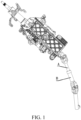
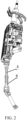
- FIG. 1 to FIG. 2 are schematic structural diagrams of an automobile steering system in related arts.
- the automobile steering system includes a steering wheel end shaft A and a steering device end shaft B.
- the steering wheel end shaft A is a rotary shaft connected with the steering wheel in a transmission way.
- the steering device end shaft B is a rotary shaft connected with the wheels in a transmission way.
- the steering wheel end shaft A is fixedly connected with the steering device end shaft B, and cannot be decoupled. In a game mode, when the user rotates the steering wheel, the wheels are driven to deflect, resulting in serious wear of the tires.
- a first aspect of embodiments of the present invention provides a clutch mechanism 100.
- the clutch mechanism 100 is mounted between a steering wheel end shaft 1 and a steering device end shaft, and is configured to realize decoupling or coupling between the steering wheel end shaft 1 and the steering device end shaft.
- structures of the conventional steering wheel end shaft A and the conventional steering device end shaft B require improvements.
- the steering wheel end shaft 1 and the steering device end shaft are coaxially arranged and radially spaced apart from each other.
- the clutch mechanism 100 includes a slidable block 14 and a driving component.
- the slidable block 14 is accommodated in a radial spacing between the steering wheel end shaft 1 and the steering device end shaft, and is configured to be driven by the driving component to move along the axial direction of the steering wheel end shaft 1 and the steering device end shaft, thereby realizing decoupling or coupling between the steering wheel end shaft 1 and the steering device end shaft.
- an automobile enters a normal driving mode, and the wheels are driven to turn when a user rotates a steering wheel.
- the steering wheel end shaft 1 and the steering device end shaft are decoupled, the automobile enters a game mode, and the wheels are not driven to turn when the user rotates the steering wheel. In this way, tire wear caused by repeated static friction between the tires and the ground after the automobile enters the game mode can be prevented, thereby facilitating implementation of solutions in an automobile game scenario.
- the clutch mechanism provided in this embodiment of the present invention is further applicable to other occasions that require decoupling or coupling, and is not limited to the steering system of the automobile. That is to say, the clutch mechanism may be configured to decouple or couple any first end shaft and second end shaft that require decoupling or coupling.
- the first end shaft being the steering wheel end shaft and the second end shaft being the steering device end shaft as an example.
- one of the steering wheel end shaft 1 and the steering device end shaft is a hollow structure.
- a part of the other of the steering wheel end shaft and the steering device end shaft in the axial direction extends into the hollow structure.
- An outer circumferential surface of the axial part and an inner circumferential surface of the hollow structure are radially spaced apart from each other to accommodate the slidable block 14.
- the part of the other of the steering wheel end shaft and the steering device end shaft in the axial direction has a first axial section 54 and a second axial section 55.
- a radial spacing between an outer circumferential surface of the first axial section 54 and the inner circumferential surface of the hollow structure is different from a radial spacing between an outer circumferential surface of the second axial section 55 and the inner circumferential surface of the hollow structure.
- the radial spacing between the outer circumferential surface of the first axial section 54 and the inner circumferential surface of the hollow structure is less than the radial spacing between the outer circumferential surface of the second axial section 55 and the inner circumferential surface of the hollow structure.
- the steering wheel end shaft 1 and the steering device end shaft are coupled, and the automobile enters the normal driving mode.
- the slidable block 14 is moved to a radial spacing between the second axial section 55 and the hollow structure along the axial direction of the steering wheel end shaft 1 and the steering device end shaft, the slidable block is engaged with only one of the second axial section 55 and the hollow structure and is separated from the other of the second axial section 55 and the hollow structure. In this way, the steering wheel end shaft 1 and the steering device end shaft are decoupled, and the automobile enters the game mode.
- the slidable block 14 may be engaged with the hollow structure, the first axial section 54, or the second axial section 55 in many manners, for example, by means of mating between a groove and a protrusion or by spline.
- the slidable block 14 is splined with the hollow structure, the first axial section 54, or the second axial section 55.
- a radial dimension of the first axial section 54 is greater than a radial dimension of the second axial section 55.
- the radial spacing between the hollow structure and the first axial section 54 is less than the radial spacing between the hollow structure and the second axial section 55.
- the inner sidewall of the slidable block 14 is spaced apart from the outer circumferential surface of the second axial section 55, and the inner sidewall of the slidable block and the outer circumferential surface of the second axial section are in a separated state, the outer sidewall of slidable block 14 is splined with the inner circumferential surface of the hollow structure.
- the steering wheel end shaft 1 and the steering device end shaft are in the decoupled state, and a rotational torque of the steering wheel is not transmitted to the steering device end shaft.
- the outer sidewall of the slidable block 14 is normally engaged with the inner circumferential surface of the hollow structure by using the splines, and the inner sidewall of the slidable block 14 is splined with the outer circumferential surface of the first axial section 54 only in the coupled state.
- the splines are formed on both the outer sidewall and the inner sidewall of the slidable block 14.
- the splines are further formed on the inner circumferential surface of the hollow structure and the outer circumferential surface of the first axial section 54.
- the inner sidewall of the slidable block 14 is a sidewall of a side of the slidable block 14 facing the steering device end shaft
- the outer sidewall of the slidable block is a sidewall of a side of the slidable block 14 facing the hollow structure.
- a structure of the slidable block 14 may vary.
- the hollow structure is a hollow cylinder, and the first axial section 54 and the second axial section 55 are both cylinder axes.
- the slidable block 14 may be a sleeve.
- the sleeve is arranged coaxially with the steering wheel end shaft 1 and the steering device end shaft. That is to say, the sleeve is sleeved outside the first axial section 54 and the second axial section 55.
- the splines are formed on an inner circumferential surface and an outer circumferential surface of the sleeve.
- External splines are formed on the outer circumferential surface of the first axial section 54 corresponding to the splines on the inner circumferential surface of the sleeve.
- Internal splines are formed on the inner circumferential surface of the hollow cylinder corresponding to the splines on the outer circumferential surface of the sleeve. In this way, during axial translation, the sleeve may be splined with or separated from the first axial section 54 to realize the coupling or the decoupling between the steering wheel end shaft 1 and the steering device end shaft.
- the driving component is connected with the slidable block 14, and is configured to drive the slidable block 14 to axially translate.
- the driving component is mounted to an outer side of the hollow structure.
- an opening is formed on the outer sidewall of the hollow structure.
- a mounting member protruding out of the hollow structure through the opening is formed on the slidable block 14. The mounting member is configured to be connected with the driving component.
- the driving component is an electric driving component as an example.
- the driving component is required to be electronically connected with a controller. If the driving component also rotates with the slidable block, a clock spring is usually required to be mounted to prevent an electric wire connected with the driving component from being broken. In this case, mounting difficulty and costs of the clutch mechanism are both increased.
- the clock spring is also referred to as a rotary connector, an airbag hairspring, or a spiral cable, which is a spiral harness.
- the clock spring is constructed as a harness having a specific length, and is in a winding arrangement. During rotation with the steering wheel end shaft 1, the harness can be adaptively loosened reversely or wound more tightly, and is not broken when the steering wheel end shaft 1 is completely turned left or right.
- the clock spring is a harness frequently used on a vehicle, which is not described in detail herein.
- a bearing 12 is coaxially disposed on the outer side of the hollow structure.
- the slidable block 14 is fixedly connected with an inner rim of the bearing 12.
- An outer rim of the bearing 12 is connected with the driving component.
- the driving component may drive the bearing 12 to translate along an axial direction of the hollow structure to drive the slidable block 14 to translate along the axial direction of the hollow structure, thereby realizing the coupling or the decoupling between the steering wheel end shaft 1 and the steering device end shaft.
- the driving component is connected with the outer rim of the bearing 12, the driving component is not affected by the rotation of the slidable block 14. That is to say, by means of the bearing 12, the axial rotation of the slidable block 14 is not transferred to the driving component. In this way, the driving component can be prevented from being driven by the slidable block 14 to rotate. Therefore, the driving component may be mounted to other relatively stationary components in the automobile, and the clock spring (which may alternatively be referred to as a spiral cable) connected with the driving component is not required to be provided. In this way, the mounting difficulty, design difficulty, and the costs of the clutch mechanism 100 are reduced.
- a mounting member is formed on the outer sidewall of the slidable block 14.
- the mounting member extends out of the hollow structure through the opening on the sidewall of the hollow structure.
- a retaining structure respectively abutting against two end surfaces of the inner rim of the bearing 12 is disposed on the mounting member.
- a limiting surface abutting against a lower end surface of the inner rim of the bearing is formed on a side of the mounting member facing the inner rim of the bearing.
- a groove is further formed on the side of the mounting member facing the inner rim of the bearing. A limiting ring 11 is inserted in the groove.
- the limiting ring 11 abuts against an upper end surface of the inner rim of the bearing 12. In this way, the inner rim of the bearing 12 can be fixed to the slidable block 14, and axial displacement of the bearing 12 relative to the slidable block 14 can be prevented.
- the bearing 12 is connected with the driving component.
- the bearing 12 is mounted in a bearing mounting ring 13, and is connected with the driving component by using the bearing mounting ring 13.
- a connecting portion radially protruding out is formed on an outer circumferential surface of the bearing mounting ring 13.
- the connecting portion may be provided with a through hole.
- An engagement member mated with the connecting portion is formed on the driving component corresponding to the connecting portion.
- a mounting hole is formed on the engagement member.
- the bearing 12 may be assembled in the bearing mounting ring 13 by means of interference fitting.
- a radial step may be formed on an inner circumferential surface of the bearing mounting ring 13. The radial step abuts against a lower end surface of the outer rim of the bearing 12. In this way, mounting stability of the bearing 12 in the bearing mounting ring 13 can be enhanced.
- the driving component may be a manual driving component, or may be an electric driving component.
- the driving component is the electric driving component.
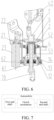
- the electric driving component includes: a power element, configured to provide a driving force; a screw rod 33, connected with an output shaft of the power element for synchronous rotation; and a helical transmission mechanism 34, threadedly connected with the screw rod 33, connected with the slidable block 14, and configured to convert rotation of the screw rod 33 to axial translation of the slidable block 14.
- the power element may be a motor 31.
- the screw rod 33 may be coaxially fixed with an output shaft of the motor 31.
- a mounting groove is formed on an end of the screw rod 33 close to the output shaft of the motor.
- the output shaft of the motor 31 is inserted and fixed in the mounting groove.
- the helical transmission mechanism 34 may be a screw nut.
- the screw nut is threadedly mounted to the screw rod 33, and is fixedly connected with the slidable block 14.
- the screw nut may be fixedly connected with the connecting portion on the bearing mounting ring 13.
- An axial direction of the screw rod 33 is parallel to the axial direction of the steering wheel end shaft 1 and the steering device end shaft.
- the motor 31 is connected with a controller of the automobile.
- the controller of the automobile is configured to receive a signal of an electrical component on the automobile, and may transmit a control command to the electrical component, to cause the electrical component to perform a corresponding action.
- the controller can receive a decoupling or coupling signal and control, according to the decoupling or coupling signal, the motor 31 to rotate.
- the screw rod 33 rotates synchronously with the motor, and drives the screw nut 34 to translate along an axial direction of the screw rod 33.
- the screw nut 34 translates axially, the slidable block 14 is driven to axially translate, thereby realizing decoupling or coupling between the steering wheel end shaft 1 and the steering device end shaft.
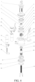
- the clutch mechanism further includes a clutch mechanism housing 41.
- the hollow structure is axially rotatably mounted in the clutch mechanism housing 41.
- the driving component is mounted to an outer side of the clutch mechanism housing 41.
- the clutch mechanism housing may be a hollow cylinder structure. Connecting portions radially protruding outward are disposed on two axial sides of the clutch mechanism housing 41.
- a power element housing of the power element is fixedly mounted to the connecting portion on one of the axial sides of the hollow cylinder structure.
- the screw rod 33 is axially rotatably mounted to the connecting portion on the other of the other axial sides of the hollow cylinder structure.
- a first mounting block is disposed on an outer circumferential edge portion on an upper end of the clutch mechanism housing, and a second mounting block is disposed on an outer side of a lower end of the clutch mechanism housing.
- the first mounting block and the second mounting block may have different structures, and may be opposite to each other in a vertical direction.
- the first mounting block is provided with a first through hole.
- the power element housing of the power element such as the motor 31 is fixed to the first mounting block by using an intermediate adapter bracket 32.
- the intermediate adapter bracket 32 may substantially be in a cuboid shape.
- a relatively large mounting hole is formed in the middle of the intermediate adapter bracket along a thickness direction.
- An output shaft of the motor 31 extends through the mounting hole and is fixedly connected with an upper end of the screw rod 33.
- Multiple relatively small positioning holes are further formed around the mounting hole. Connecting members such as screws are caused to extend through the positioning holes to be threadedly connected with the power element housing of the motor 31, thereby fixedly connecting the power element housing of the motor 31 with the intermediate adapter bracket 32.
- a second through hole is formed on a sidewall of the intermediate adapter bracket 32 corresponding to the first through hole on the first mounting block.
- the intermediate adapter bracket 32 may be fixedly connected with the first mounting block by using a connecting member such as a bolt extending through the first through hole and the second through hole.
- a through hole is formed on the second mounting block.
- a rotary bearing 43 is fixed in the through hole.
- a lower end of the screw rod 33 is inserted and fixed in the rotary bearing 43. In this way, when the output shaft of the motor 31 rotates, the screw rod 33 can rotates synchronously with the output shaft, but does not drive the clutch mechanism housing 41 to rotate.
- the clutch mechanism housing 41 is fixed to other stationary components in the automobile, such as a steering column mounting housing 200.
- an adapter 42 is further formed on the clutch mechanism housing.
- the clutch mechanism housing 41 may be connected with the other stationary components by using the adapter 42.
- the clutch mechanism housing 41 is stationary relative to the automobile.
- the steering wheel end shaft 1 and the steering device end shaft may be in a rotating state. Therefore, the hollow structure is required to be axially rotatably mounted in the clutch mechanism housing 41.
- bearings are respectively disposed on upper and lower sides of a part of the hollow structure extending into the clutch mechanism housing 41, the hollow structure is fixedly connected with inner rims of the bearings, and outer rims of the bearings are fixedly connected with the clutch mechanism housing.
- multiple arcuate plates spaced apart from each other along a circumferential direction are formed on a lower portion of the hollow structure.
- the part of the other of the steering wheel end shaft and the steering device end shaft in the axial direction extends into a circular space defined by the plurality of arcuate plates.
- the hollow structure is the steering wheel end shaft 1, and the other of the steering wheel end shaft and the steering device end shaft is the steering device end shaft, for example.
- the slidable block 14 is accommodated between inner sidewalls of the arcuate plates and the outer circumferential surface of the steering device end shaft.
- the mounting member on the slidable block 14 protrudes out of the hollow structure through a spacing between the adjacent two arcuate plates, so as to be connected with the driving component on the outer side of the hollow structure.
- Internal splines configured to be splined with the slidable block are formed on the inner sidewalls of the arcuate plates.
- a radial dimension of a lower portion of a part of the steering device end shaft located in the hollow structure is greater than a radial dimension of an upper portion of a part of the steering device end shaft.
- External splines configured to be splined with the slidable block are formed on an outer circumferential surface of the lower portion.
- the base 61 may be, for example, a cylindrical structure.
- Arcuate holes are formed on an upper end plate of the cylindrical structure corresponding to the arcuate plates.
- the arcuate plates may be inserted into the base 61 through the arcuate holes. Through holes are further formed on lower ends of the arcuate plates. Mounting holes corresponding to the through holes are formed on a sidewall of the cylindrical structure.
- the arcuate plates After the arcuate plates are inserted into the cylindrical structure, the arcuate plates may be attached to an inner sidewall of the cylindrical structure. In this case, the through holes on the arcuate plates are brought into communication with the mounting holes on the sidewall of the cylindrical structure. Therefore, the arcuate plates may be fixed with the base by using, for example, screws.
- the first bearing 62 is mounted to an outer circumferential surface of the base 61.
- the first bearing 62 may be, for example, assembled on the outer circumferential surface of the base 61 by means of interference fitting.
- a first limiting structure respectively abutting against two end surfaces of an inner rim of the first bearing 62 may be formed on the outer circumferential surface of the base 61.
- the first limiting structure includes a first limiting surface formed on the outer circumferential surface of the base 61.
- the first limiting surface is configured to abut against an upper end surface of the inner rim of the first bearing 62.
- the first limiting structure includes a first limiting ring 63 mounted to an outer sidewall of the base 61. The first limiting ring 63 abuts against a lower end surface of the inner rim of the first bearing 62.
- a groove is formed on the outer circumferential surface of the base 61 along a circumferential direction.
- the first limiting ring 63 may be mounted in the groove.
- a second limiting structure respectively abutting against two end surfaces of an inner rim of the second bearing 4 may be formed on the outer circumferential surface of the upper portion of the hollow structure.
- the second limiting structure includes a second limiting surface formed on the outer circumferential surface of the hollow structure. The second limiting surface is configured to abut against an upper end surface of the inner rim of the second bearing 4.
- the second limiting structure includes a second limiting ring 5 mounted to the outer sidewall of the hollow structure. The second limiting ring 5 abuts against a lower end surface of the inner rim of the second bearing 4.
- a groove is formed on the outer circumferential surface of the hollow structure along the circumferential direction.
- the second limiting ring 5 may be mounted in the groove.
- the outer rims of the first bearing 62 and the second bearing 4 are both fixedly connected with the clutch mechanism housing 41.
- a second aspect of the embodiments of the present invention provides a steering system.
- the steering system includes a steering wheel end shaft 1, a steering device end shaft, and a clutch mechanism 100 configured to realize decoupling or coupling between the steering wheel end shaft 1 and the steering device end shaft.
- the clutch mechanism 100 is the clutch mechanism in the first aspect of the embodiments of the present invention.
- an automobile After the steering wheel end shaft 1 and the steering device end shaft are decoupled by means of the above clutch mechanism, an automobile enters a game mode.
- the game mode the user is not subjected to resistance when operating the steering wheel, which affects the operation feeling of the steering wheel and degrades entertainment experience of the user.
- the embodiments of the present invention further improve the steering system.
- the steering system further includes a torque feedback mechanism.
- the torque feedback mechanism is configured to apply a reverse feedback torque to the steering wheel end shaft 1 according to a torsional torque of the steering wheel end shaft 1 in a decoupled state, to prevent the steering wheel end shaft 1 from rotating, thereby enhancing the operation feeling of the steering wheel.
- the reverse feedback torque is applied to the steering wheel by using the torque feedback mechanism according to the torsional torque.
- a specific resistance is applied to the steering wheel, and a user has a "heavy" feeling when operating the steering wheel to turn in the game mode, which is equivalent to driving on a real road, thereby improving the operation experience of the user when using the automobile for game entertainment.
- a correspondence between the feedback torque and a detected torsional torque is established by using an experiment and is prestored in a controller.
- the controller controls, according to the detected torsional torque, a magnitude of the feedback torque outputted by the torque feedback mechanism. In this way, optimal game experience can be provided for the user.
- the torque feedback mechanism includes: a torque detection element, configured to detect the torsional torque of the steering wheel end shaft 1 in the decoupled state; a power element, configured to provide a driving force; a transmission mechanism, configured to transmit the driving force to the steering wheel end shaft 1 to apply the reverse feedback torque to the steering wheel end shaft 1; and a controller, configured to control, according to the torsional torque detected by the torque detection element, the power element to provide the driving force.
- the torque detection element may be, for example, a torque sensor.
- the power element may be, for example, a motor 23.
- the controller may be, for example, a single-chip microcomputer, a programmable logic controller, or the like. The controller may control an input current of the motor according to the magnitude of the detected torsional torque, thereby changing a driving force outputted by the motor 23.
- the above motor 23 applies the reverse feedback torque to the steering wheel end shaft 1 by operating in a motor mode.
- the motor 23 may alternatively be controlled in the generator mode to apply the reverse feedback torque to the steering wheel end shaft 1.
- the steering wheel end shaft 1 is driven to rotate, and is connected with a rotor of the motor 23 in a transmission way. In this way, the rotor of the motor 23 is driven to rotate, thereby causing the motor 23 to be in the generator mode.
- the driving force is transmitted to the steering wheel end shaft 1 by the transmission mechanism.
- the transmission mechanism may be, for example, a conveyor belt.
- a first roller may be mounted to the output shaft of the motor, and a second roller may be mounted to the steering wheel end shaft 1.
- the first roller and the second roller are connected with each other in a transmission way by the conveyor belts mounted to the first roller and the second roller.
- the transmission mechanism in order to reduce a size of the torque feedback mechanism to conveniently mount the torque feedback mechanism, includes a first gear 21 connected with the output shaft of the motor for synchronous rotation and a second gear 2 connected with the steering wheel end shaft 1 for synchronous rotation.
- the first gear 21 is meshed with the second gear 2.
- the first gear 21 may be coaxially fixed to the output shaft of the motor 23.
- the second gear 2 may be coaxially fixed to the steering wheel end shaft 1.
- the output shaft of the motor 23 is parallel to the steering wheel end shaft 1.
- the driving force outputted by the motor 23 may be transmitted to the steering wheel end shaft 1 by means of the first gear 21 and the second gear 2, thereby applying the feedback torque to the steering wheel end shaft 1.
- a diameter of the first gear 21 is less than a diameter of the second gear 2.
- the second gear 2 is coaxially fixed to the steering wheel end shaft 1 in the following manner.
- the second gear 2 is an annular gear ring.
- the annular ring gear is sleeved outside the steering wheel end shaft 1.
- a retaining structure that can respectively abut against two axial end surfaces of the second gear 2 is disposed on the outer sidewall of the steering wheel end shaft 1.
- the retaining structure includes a retaining surface formed on the outer circumferential surface of the steering wheel end shaft 1.
- the retaining surface abuts against an upper end surface of the second gear 2, to avoid an axial upward displacement of the second gear 2 relative to the steering wheel end shaft 1.
- the retaining structure further includes a retaining ring 3 coaxially mounted to the outer sidewall of the steering wheel end shaft 1.
- the retaining ring 3 abuts against a lower end surface of the second gear 2, to avoid an axial downward displacement of the second gear 2 relative to the steering wheel end shaft 1.
- a groove is formed on the outer sidewall of the steering wheel end shaft 1 along a circumferential direction. The retaining ring 3 is inserted and tightly fixed in the groove.
- the second gear 2 is connected with the steering wheel end shaft 1 for synchronous rotation.
- a protrusion is formed on the outer sidewall of the steering wheel end shaft 1
- a notch is formed on an edge portion of an inner rim of the second gear 2 corresponding to the protrusion. The protrusion is accommodated in the notch. In this way, the second gear 2 can be prevented from circumferentially displacing relative to the steering wheel end shaft 1.
- the steering wheel end shaft 1 and the steering device end shaft are required to be coupled to cause the automobile to enter the normal driving mode.
- the steering wheel end shaft 1 and the steering device end shaft are required to be aligned to each other.
- the clutch mechanism is splined with the steering wheel end shaft 1 and the steering device end shaft.
- the steering wheel end shaft 1 and the steering device end shaft are decoupled, since the user operates the steering wheel to turn during a game, after completion of the game, the steering wheel may no longer be located at a steering angle before the decoupling.
- the deflection of the steering wheel causes the steering wheel end shaft 1 to deflect.
- the steering wheel end shaft 1 and the steering device end shaft cannot realize re-coupling after the game, which affects normal use of the automobile.
- the steering system further includes a reset mechanism.
- the reset mechanism is configured to drive the steering wheel end shaft 1 to be reset after completion of the game mode, to enable the clutch mechanism to realize coupling between the steering wheel end shaft 1 and the steering device end shaft.
- the resetting of the steering wheel end shaft 1 means that the steering wheel end shaft 1 is reset to the steering angle before the decoupling, and before the decoupling of the steering wheel end shaft 1, the steering wheel end shaft 1 and the steering device end shaft are aligned to each other.
- the reset mechanism includes: an angle detection element, configured to detect a steering angle of the steering wheel end shaft 1 before completion of the game mode and a steering angle of the steering wheel end shaft 1 after completion of the game mode; a power element, configured to provide a driving force; a transmission mechanism, configured to transmit the driving force to the steering wheel end shaft 1 to drive the steering wheel end shaft 1 to be reset to the steering angle before the decoupling; and a controller, configured to control, according to the steering angle detected by the angle detection element, the power element to provide the driving force.
- the angle detection element may be an angle sensor.
- the angle sensor may be integrated with the torque sensor described above. That is to say, the torsional torque of the steering wheel end shaft 1 and the steering angle of the steering wheel end shaft 1 may be detected by using the torque-angle sensor. In this way, an overall size of the torque feedback mechanism is reduced, thereby facilitating mounting of the system.
- the torque-angle sensor may be mounted to the steering wheel end shaft 1, or may be integrated in the motor 23.
- the torsional torque and the steering angle of the steering wheel end shaft 1 are indirectly detected by detecting a torsional torque and a steering angle of the output shaft of the motor 23.
- the controller precisely controls an output rotation speed and a rotation quantity of the motor 23 to cause the steering wheel end shaft 1 to be reset to an initial angle before the decoupling after completion of the game.
- the corresponding output rotation speed and rotation quantity of the motor 23 causing the steering wheel end shaft 1 to be reset to the initial angle before the decoupling may be obtained according to the steering angle detected by the angle detection element.
- the controller controls the power element to provide the corresponding driving force
- the driving force is calculated according to the output rotation speed and the rotation quantity of the motor 23.
- a hardware structure of the reset mechanism may be same as a hardware structure of the torque feedback mechanism described above, except that magnitudes of the outputted driving forces are different.
- the driving force outputted by the torque feedback mechanism is generally relatively small, and is merely used for improving operation experience of a user.
- the driving force outputted by the reset mechanism is generally relatively large, and is intended to drive the steering wheel end shaft 1 to be turned and reset after completion of the game.
- the power element in the reset mechanism or the torque feedback mechanism may be fixed to the clutch mechanism housing of the clutch mechanism.
- the power element of the reset mechanism or the torque feedback mechanism may be fixed to the first mounting block of the clutch mechanism housing. Specifically, a mounting hole is formed on the first mounting block corresponding to the power element of the reset mechanism or the torque feedback mechanism.
- the power element is the motor 23.
- the power element housing of the motor 23 is mounted to the first mounting block by using the intermediate adapter bracket 22.
- the intermediate adapter bracket 22 is in a plate structure.
- a relatively large through hole is formed on the plate structure.
- the output shaft of the motor 23 extends through the through hole.
- Multiple small positioning holes are formed around the through hole.
- Multiple mounting holes are formed on an end portion of the power element housing of the motor 23 corresponding to the positioning holes.
- the power element housing of the motor 23 is fixed to the intermediate adapter bracket 22 by using connecting members such as screws extending through the positioning holes and the mounting holes.
- multiple small holes are further formed on the intermediate adapter bracket 22 corresponding to the mounting holes on the first mounting block.
- the intermediate adapter bracket 22 is fixed to the first mounting block by using connecting members such as bolts extending through the small holes and the mounting holes.
- the steering wheel end shaft 1 and the steering device end shaft are decoupled by using the clutch mechanism 100, the steering wheel cannot be turned in one direction infinitely, which, otherwise, does not correspond to an actual situation, resulting in poor driving experience. More importantly, a clock spring in the steering wheel may be broken, resulting in a failure of many electronic buttons on the steering wheel. Therefore, after the decoupling, limiting is usually required.
- a limiting mechanism configured to limit a range of steering angle of the steering wheel end shaft 1 in the decoupled state is further disposed in the steering system.
- the steering wheel end shaft 1 is a hollow structure. An part of the steering device end shaft in an axial direction extends into the hollow structure.
- the limiting mechanism includes a limiting nut 6 threadedly connected with an end 56 of the steering device end shaft located in the hollow structure. External splines mated with splines on an inner circumferential surface of the hollow structure are formed on an outer circumferential surface of the limiting nut 6. Limiting portions configured to limit displacements on two axial sides of the limiting nut are disposed on the inner circumferential surface of the hollow structure and/or an outer circumferential surface of the steering device end shaft.
- inner trapezoidal threads are machined on an inner circumferential surface of the limiting nut 6, and outer trapezoidal threads are machined on an outer circumferential surface of an upper end portion of the steering device end shaft.
- the inner trapezoidal threads are mated with the outer trapezoidal threads.
- Outer rectangular splines are machined on the outer circumferential surface of the limiting nut 6, and inner rectangular splines are correspondingly machined on an inner circumferential surface of the steering wheel end shaft 1.
- the outer rectangular splines are mated with the inner rectangular splines.
- the limiting portions configured to limit the displacements on the two axial sides of the limiting nut 6 may be, for example, limiting posts.
- the limiting nut 6 converts the rotation to linear movement to translate up or down along an axial direction.
- a top dead center may depend on a corresponding structure of the steering wheel end shaft 1.
- a bottom dead center may depend on a corresponding structure of the steering device end shaft. Since the steering wheel end shaft 1 and the steering device end shaft are not axially moved, positions of the top dead center and the bottom dead center are accurate and reliable. Leads of the inner trapezoidal transmission threads are adjusted according to a stroke of the limiting nut 6, so as to precisely control an extreme rotation angle of the steering wheel.
- the top dead center and the bottom dead center may alternatively be formed on either the steering wheel end shaft 1 or the steering device end shaft.
- the top dead center is formed on the steering device end shaft
- the bottom dead center is formed on the steering wheel end shaft 1.
- the top dead center and the bottom dead center herein are positions of the above limiting posts.
- the limiting nut 6 is first required to be positioned in the steering wheel end shaft 1, and then the steering device end shaft is inserted into and threadedly connected with the limiting nut 6.
- a through hole is formed on a sidewall of the nut 6.
- a shaft pin 7 is first caused to extend through the through hole to position the limiting nut 6 in the steering wheel end shaft 1, then the steering device end shaft is threadedly connected with the limiting nut 6, and then the shaft pin is removed.
- the steering device end shaft in order to reduce mounting and manufacturing difficulty of the steering device end shaft, includes a steering sleeve 53 and a steering shaft 70 that are disposed coaxially.
- the steering shaft 70 extends into the steering sleeve 53 and is splined with the steering sleeve 53.
- the steering sleeve 53 is located on an inner side of the steering wheel end shaft 1.
- External splines that can be splined with the slidable block 14 are machined on an outer circumferential surface of a lower portion of the steering sleeve.
- Outer threads that can be threadedly connected with the limiting nut are machined on an outer circumferential surface of an upper end of the steering sleeve.
- Internal splines splined with the steering shaft are machined on an inner circumferential surface of the steering sleeve.
- the upper end of the steering sleeve 53 is supported in the steering wheel end shaft 1 by using a sleeve bearing 52.
- the inner circumferential surface of the steering wheel end shaft 1 is tightly mated with an outer rim of the sleeve bearing 52, and an inner rim of the sleeve bearing 52 is tightly mated with an outer circumferential surface of the steering sleeve 53. In this way, the steering device end shaft can be stably mounted in the steering wheel end shaft 1.
- a limiting structure that can respectively abut against upper and lower end surfaces of the inner rim of the sleeve bearing 52 is formed on the outer circumferential surface of the steering sleeve 53.
- the limiting structure includes a limiting surface that is formed on the outer circumferential surface of the steering sleeve 53 and can abut against the lower end surface of the bearing and a limiting ring 51 mounted to the outer circumferential surface of the steering sleeve 53.
- the limiting ring 51 abuts against the upper end surface of the sleeve bearing 52.
- a groove configured to mount the limiting ring 51 may be machined on the outer circumferential surface of the steering sleeve 53.
- a third aspect of the embodiments of the present invention provides an automobile.
- the automobile includes the steering system in the second aspect of the embodiments of the present invention.
Landscapes
- Engineering & Computer Science (AREA)
- Chemical & Material Sciences (AREA)
- Combustion & Propulsion (AREA)
- Transportation (AREA)
- Mechanical Engineering (AREA)
- Multimedia (AREA)
- Human Computer Interaction (AREA)
- Power Steering Mechanism (AREA)
- Steering Controls (AREA)
- Mechanical Operated Clutches (AREA)
Claims (13)
- Kupplungsmechanismus, der Folgendes umfasst:einen verschiebbaren Block (14), der in einem radialen Abstand zwischen einer ersten Endwelle (1) und einer zweiten Endwelle untergebracht ist, die koaxial angeordnet und radial voneinander beabstandet sind und dazu eingerichtet sind, sich entlang einer axialen Richtung der ersten Endwelle (1) und der zweiten Endwelle zu verschieben, um eine Entkopplung oder Kupplung zwischen der ersten Endwelle (1) und der zweiten Endwelle zu realisieren; undeine Antriebskomponente, die dazu eingerichtet ist, den verschiebbaren Block (14) anzutreiben, um ihn entlang der axialen Richtung der ersten Endwelle (1) und der zweiten Endwelle zu verschieben, dadurch gekennzeichnet, dasseine der ersten Endwelle und der zweiten Endwelle eine hohle Struktur ist; ein Teil der anderen der ersten Endwelle und der zweiten Endwelle in der axialen Richtung sich in die hohle Struktur erstreckt; und eine äußere Umfangsfläche des Teils radial von einer inneren Umfangsfläche der hohlen Struktur beabstandet ist, um den verschiebbaren Block (14) aufzunehmen;das Teil der anderen von der ersten Endwelle und der zweiten Endwelle in der axialen Richtung einen ersten axialen Abschnitt (54) und einen zweiten axialen Abschnitt (55) aufweist; ein radialer Abstand zwischen einer äußeren Umfangsfläche des ersten axialen Abschnitts (54) und der inneren Umfangsfläche der Hohlstruktur kleiner ist als ein radialer Abstand zwischen einer äußeren Umfangsfläche des zweiten axialen Abschnitts (55) und der inneren Umfangsfläche der Hohlstruktur; und in einer Kupplungsposition eine äußere Seitenwand des verschiebbaren Blocks (14) mit der inneren Umfangsfläche der hohlen Struktur in Eingriff ist und eine innere Seitenwand des verschiebbaren Blocks (14) mit der äußeren Umfangsfläche des ersten axialen Abschnitts (54) in Eingriff ist, wobei der verschiebbare Block (14) normalerweise mit der hohlen Struktur verzahnt ist und mit dem ersten axialen Abschnitt (54) an der Kupplungsposition verzahnt ist.
- Kupplungsmechanismus nach Anspruch 1, wobei der verschiebbare Block (14) eine Hülse ist und die Hülse koaxial mit der ersten Endwelle (1) und der zweiten Endwelle angeordnet ist.
- Kupplungsmechanismus nach einem der Ansprüche 1 bis 2, wobei die Antriebskomponente an einer Außenseite der hohlen Struktur angeordnet ist und eine Öffnung an einer Seitenwand der hohlen Struktur ausgebildet ist, um die Antriebskomponente mit dem verschiebbaren Block (14) zu verbinden.
- Kupplungsmechanismus nach Anspruch 3, bei dem ein Lager (12) koaxial an der Außenseite der Hohlstruktur angeordnet ist; der verschiebbare Block (14) fest mit einem inneren Rand des Lagers (12) verbunden ist; und ein äußerer Rand des Lagers (12) mit der Antriebskomponente verbunden ist, wobei vorzugsweise:
ein Montageelement an der äußeren Seitenwand des verschiebbaren Blocks (14) ausgebildet ist; das Montageelement sich aus der hohlen Struktur durch die Öffnung an der Seitenwand der hohlen Struktur erstreckt, um mit der Antriebskomponente verbunden zu werden; und Begrenzungsstrukturen, die jeweils an zwei Endflächen des inneren Randes des Lagers (12) anliegen, an dem Montageelement angeordnet sind, oder das Lager (12) in einem Lagermontagering (13) montiert ist; ein Verbindungsabschnitt, der dazu eingerichtet ist, mit der Antriebskomponente verbunden zu werden, an einer äußeren Umfangsfläche des Lagermontagerings (13) ausgebildet ist; und eine radiale Stufe, die dazu eingerichtet ist, an einer unteren Endfläche des äußeren Randes des Lagers (12) anzustoßen, an einer inneren Umfangsfläche des Lagermontagerings (13) entlang einer Umfangsrichtung ausgebildet ist. - Kupplungsmechanismus nach einem der Ansprüche 1 bis 4, wobei die Antriebskomponente eine elektrische Antriebskomponente ist; und
die elektrische Antriebskomponente umfasst:ein Leistungselement, das dazu eingerichtet ist, eine Antriebskraft bereitzustellen;eine Gewindestange (33), die mit einer Abtriebswelle des Leistungselements zur synchronen Drehung verbunden ist; undeinen schraubenförmigen Übertragungsmechanismus (34), der mit der Gewindestange (33) verschraubt und mit dem verschiebbaren Block (14) verbunden ist und dazu eingerichtet ist, die Drehung der Gewindestange (33) in eine axiale Verschiebung des verschiebbaren Blocks (14) umzuwandeln. - Kupplungsmechanismus nach Anspruch 5, der ferner ein Kupplungsmechanismusgehäuse (41) umfasst, wobei die hohle Struktur axial drehbar in dem Kupplungsmechanismusgehäuse (41) angebracht ist; und die Antriebskomponente an einer Außenseite des Kupplungsmechanismusgehäuses (41) angebracht und an dem Kupplungsmechanismusgehäuse (41) befestigt ist, wobei vorzugsweise:
eine Vielzahl von bogenförmigen Platten, die entlang einer Umfangsrichtung voneinander beabstandet sind, an einem unteren Abschnitt der hohlen Struktur ausgebildet sind, und der Teil der anderen der ersten Endwelle und der zweiten Endwelle in der axialen Richtung sich in einen kreisförmigen Raum erstreckt, der durch die Vielzahl von bogenförmigen Platten definiert ist; der Kupplungsmechanismus umfasst ferner eine Basis (61); bogenförmige Löcher, die Strukturen der bogenförmigen Platten entsprechen, sind an der Basis (61) ausgebildet; die unteren Enden der mehreren bogenförmigen Platten durch die bogenförmigen Löcher in die Basis (61) eingeführt und an der Basis (61) befestigt sind; ein erstes Lager (62) koaxial in einem radialen Abstand zwischen der Basis (61) und dem Kupplungsmechanismusgehäuse (41) angebracht ist; und ein zweites Lager (4) koaxial in einem radialen Abstand zwischen einem oberen Abschnitt der hohlen Struktur und dem Kupplungsmechanismusgehäuse (41) angebracht ist. - Kupplungsmechanismus nach Anspruch 6, wobei radial nach außen vorstehende Verbindungsabschnitte an gegenüberliegenden Positionen an zwei axialen Seiten des Kupplungsmechanismusgehäuses (41) angeordnet sind; ein Antriebselementgehäuse des Antriebselements fest an dem Verbindungsabschnitt an einer der axialen Seiten des Kupplungsmechanismusgehäuses (41) angebracht ist; und die Schraubenstange (33) axial drehbar an dem Verbindungsabschnitt an der anderen der axialen Seiten des Kupplungsmechanismusgehäuses (41) angebracht ist.
- Kupplungsmechanismus nach einem der Ansprüche 6 bis 7, wobei ein Adapter (42), der dazu eingerichtet ist, das Kupplungsmechanismusgehäuse (41) an einer Fahrzeugkarosserie zu befestigen, ferner an dem Kupplungsmechanismusgehäuse (41) angeordnet ist.
- Lenksystem, umfassend eine erste Endwelle (1), eine zweite Endwelle und einen Kupplungsmechanismus (100), der dazu eingerichtet ist, eine Entkopplung oder Kopplung zwischen der ersten Endwelle (1) und der zweiten Endwelle zu realisieren, wobei es sich bei dem Kupplungsmechanismus (100) um den Kupplungsmechanismus nach einem der Ansprüche 1 bis 8 handelt, wobei es sich bei der ersten Endwelle vorzugsweise um eine Lenkrad-Endwelle (1) und bei der zweiten Endwelle um eine Lenkvorrichtungs-Endwelle handelt.
- Lenksystem nach Anspruch 9, das ferner einen Drehmoment-Rückkopplungsmechanismus umfasst, wobei der Drehmoment-Rückkopplungsmechanismus dazu eingerichtet ist, ein umgekehrtes Rückkopplungsdrehmoment auf die erste Endwelle (1) entsprechend einem Torsionsdrehmoment der ersten Endwelle (1) in einem entkoppelten Zustand aufzubringen, um ein Betriebsgefühl eines mit der ersten Endwelle (1) übertragungsmäßig verbundenen Lenkrads zu verbessern, wobei der Drehmoment-Rückkopplungsmechanismus vorzugsweise umfasst:ein Drehmomenterfassungselement, das dazu eingerichtet ist, das Torsionsmoment der ersten Endwelle im entkoppelten Zustand zu erfassen;ein Leistungselement, das dazu eingerichtet ist, eine Antriebskraft bereitzustellen;einen Getriebemechanismus, der dazu eingerichtet ist, die Antriebskraft auf die erste Endwelle zu übertragen, um das Rückkopplungsdrehmoment auf die erste Endwelle aufzubringen; undeine Steuerung, die dazu eingerichtet ist, entsprechend dem von dem Drehmomenterfassungselement erfassten Torsionsmoment das Leistungselement zu steuern, um die Antriebskraft bereitzustellen;wobei das Leistungselement vorzugsweise ein Motor (23) ist; der Getriebemechanismus ein erstes Zahnrad (21) umfasst, das mit einer Abtriebswelle des Motors (23) zur synchronen Drehung verbunden ist, und ein zweites Zahnrad (2), das mit der ersten Endwelle (1) zur synchronen Drehung verbunden ist, wobei das erste Zahnrad (21) mit dem zweiten Zahnrad (2) in Eingriff steht; und ein Außendurchmesser des ersten Zahnrads (21) kleiner ist als ein Außendurchmesser des zweiten Zahnrads (2), wobei vorzugsweise:
das zweite Zahnrad (2) koaxial an der ersten Endwelle (1) befestigt ist; Haltekonstruktionen, die jeweils an zwei axialen Endflächen des zweiten Zahnrads (2) anliegen, an einer äußeren Seitenwand der ersten Endwelle (1) angeordnet sind; ein Vorsprung an der äußeren Seitenwand der ersten Endwelle (1) ausgebildet ist; eine Kerbe an einem Kantenabschnitt eines inneren Rands des zweiten Zahnrads (2) ausgebildet ist, der dem Vorsprung entspricht, und der Vorsprung in der Kerbe untergebracht ist. - Lenksystem nach Anspruch 9, das ferner einen Rückstellmechanismus umfasst, wobei der Rückstellmechanismus dazu eingerichtet ist, die erste Endwelle anzutreiben, um nach Abschluss der Entkopplung zurückgestellt zu werden, damit der Kupplungsmechanismus die erste Endwelle und die zweite Endwelle koppeln kann, wobei der Rückstellmechanismus vorzugsweise umfasst:ein Winkelerfassungselement, das dazu eingerichtet ist, einen Lenkwinkel der ersten Endwelle vor der Entkopplung und einen Lenkwinkel der ersten Endwelle nach Abschluss der Entkopplung zu erfassen;ein Leistungselement, das dazu eingerichtet ist, eine Antriebskraft bereitzustellen;einen Übertragungsmechanismus, der dazu eingerichtet ist, die Antriebskraft auf die erste Endwelle zu übertragen, um die erste Endwelle so anzutreiben, dass sie vor dem Abkoppeln auf den Lenkwinkel zurückgestellt wird; undeine Steuerung, die dazu eingerichtet ist, entsprechend dem von dem Winkelerfassungselement erfassten Lenkwinkel das Leistungselement zu steuern, um die Antriebskraft bereitzustellen;wobei das Leistungselement vorzugsweise ein Motor (23) ist; der Getriebemechanismus ein erstes Zahnrad (21), das mit einer Abtriebswelle des Motors (23) zur synchronen Drehung verbunden ist, und ein zweites Zahnrad (2), das mit der ersten Endwelle (1) zur synchronen Drehung verbunden ist, umfasst, wobei das erste Zahnrad (21) mit dem zweiten Zahnrad (2) in Eingriff steht; und ein Außendurchmesser des ersten Zahnrads (21) kleiner als ein Außendurchmesser des zweiten Zahnrads (2) ist, wobei vorzugsweise:
das zweite Zahnrad (2) koaxial an der ersten Endwelle (1) befestigt ist; Haltekonstruktionen, die jeweils an zwei axialen Endflächen des zweiten Zahnrads (2) anliegen, an einer äußeren Seitenwand der ersten Endwelle (1) angeordnet sind; ein Vorsprung an der äußeren Seitenwand der ersten Endwelle (1) ausgebildet ist; eine Kerbe an einem Kantenabschnitt eines inneren Rands des zweiten Zahnrads (2) ausgebildet ist, der dem Vorsprung entspricht, und der Vorsprung in der Kerbe untergebracht ist. - Lenksystem nach einem der Ansprüche 9 bis 11, wobei ein Begrenzungsmechanismus, der dazu eingerichtet ist, einen Bereich des Lenkwinkels der ersten Endwelle im entkoppelten Zustand zu begrenzen, ferner in dem Lenksystem angeordnet ist, wobei vorzugsweise:
die erste Endwelle (1) eine hohle Struktur ist; sich ein Teil der zweiten Endwelle in einer axialen Richtung in die hohle Struktur erstreckt; der Begrenzungsmechanismus eine Begrenzungsmutter (6) umfasst, die mit einem Ende (56) der zweiten Endwelle, das sich in der hohlen Struktur befindet, verschraubt ist; Außenverzahnungen, die mit Verzahnungen auf einer inneren Umfangsfläche der hohlen Struktur zusammenpassen, sind auf einer äußeren Umfangsfläche der Begrenzungsmutter (6) ausgebildet; und ein Begrenzungsabschnitt, der dazu eingerichtet ist, Verschiebungen von zwei axialen Seiten der Begrenzungsmutter (6) zu begrenzen, ist ferner auf der inneren Umfangsfläche der hohlen Struktur und/oder einer äußeren Umfangsfläche der zweiten Endwelle angeordnet, wobei weiter bevorzugt:
die zweite Endwelle eine Lenkhülse (53) und eine Lenkwelle (70) umfasst, die koaxial angeordnet sind; die Lenkwelle (70) sich in die Lenkhülse (53) erstreckt und mit der Lenkhülse (53) für eine synchrone Drehung verbunden ist; die Lenkhülse (53) in der hohlen Struktur angeordnet ist; und Außengewinde, die dazu eingerichtet sind, mit der Begrenzungsmutter (6) verschraubt zu werden, und Außenverzahnungen, die dazu eingerichtet sind, mit dem verschiebbaren Block verzahnt zu werden, um die erste Endwelle mit der zweiten Endwelle zu koppeln, an einer äußeren Umfangsfläche der Lenkhülse (53) bearbeitet sind. - Ein Kraftfahrzeug, das die Lenkung nach einem der Ansprüche 9 bis 12 umfasst.
Applications Claiming Priority (2)
| Application Number | Priority Date | Filing Date | Title |
|---|---|---|---|
| CN201911023715.8A CN112706828B (zh) | 2019-10-25 | 2019-10-25 | 离合机构、转向系统和汽车 |
| PCT/CN2020/117122 WO2021077970A1 (zh) | 2019-10-25 | 2020-09-23 | 离合机构、转向系统和汽车 |
Publications (3)
| Publication Number | Publication Date |
|---|---|
| EP4046893A1 EP4046893A1 (de) | 2022-08-24 |
| EP4046893A4 EP4046893A4 (de) | 2023-01-11 |
| EP4046893B1 true EP4046893B1 (de) | 2024-04-03 |
Family
ID=75540721
Family Applications (1)
| Application Number | Title | Priority Date | Filing Date |
|---|---|---|---|
| EP20880207.4A Active EP4046893B1 (de) | 2019-10-25 | 2020-09-23 | Kupplungsmechanismus, lenksystem und kraftfahrzeug |
Country Status (9)
| Country | Link |
|---|---|
| US (1) | US11958542B2 (de) |
| EP (1) | EP4046893B1 (de) |
| JP (1) | JP7399278B2 (de) |
| KR (1) | KR102780885B1 (de) |
| CN (1) | CN112706828B (de) |
| AU (1) | AU2020371777B2 (de) |
| BR (1) | BR112022007824A2 (de) |
| ES (1) | ES2984534T3 (de) |
| WO (1) | WO2021077970A1 (de) |
Families Citing this family (4)
| Publication number | Priority date | Publication date | Assignee | Title |
|---|---|---|---|---|
| CN114560008B (zh) * | 2020-11-27 | 2024-03-19 | 比亚迪股份有限公司 | 转向系统和车辆 |
| CN115675616B (zh) * | 2021-07-30 | 2024-10-11 | 比亚迪股份有限公司 | 转向器 |
| CN116135666B (zh) * | 2021-11-18 | 2024-10-29 | 比亚迪股份有限公司 | 用于车辆的转向系统和车辆 |
| CN119198140B (zh) * | 2024-10-25 | 2025-07-01 | 北京博科测试系统股份有限公司 | 一种电驱动转向系统测试台 |
Family Cites Families (42)
| Publication number | Priority date | Publication date | Assignee | Title |
|---|---|---|---|---|
| JPS4851932U (de) * | 1971-10-27 | 1973-07-06 | ||
| JPS5728945U (de) * | 1980-07-25 | 1982-02-16 | ||
| US4556116A (en) * | 1984-08-30 | 1985-12-03 | Eaton Corporation | Fail-safe mechanism for an electrical power assisted steering system |
| JPH03163224A (ja) * | 1989-11-22 | 1991-07-15 | Tochigi Fuji Ind Co Ltd | ハブクラッチ及びそのストッパ加工方法 |
| JPH05272611A (ja) * | 1992-03-25 | 1993-10-19 | Toyota Motor Corp | 送り装置 |
| JP3097542B2 (ja) * | 1996-02-05 | 2000-10-10 | トヨタ自動車株式会社 | 自動操舵装置 |
| JP3507446B2 (ja) * | 2001-02-05 | 2004-03-15 | 株式会社 神崎高級工機製作所 | 作業車両の走行装置 |
| CN1336498A (zh) * | 2001-02-15 | 2002-02-20 | 何开明 | 螺旋式离合机构 |
| JP2003014070A (ja) * | 2001-07-02 | 2003-01-15 | Smc Corp | 電動アクチュエータ |
| DE20213472U1 (de) * | 2002-09-02 | 2003-01-16 | Chen, Hsi-Tsai, Taichung | Kupplungsvorrichtung |
| JP4089374B2 (ja) | 2002-09-26 | 2008-05-28 | 株式会社ジェイテクト | 車両用操舵装置 |
| JP2004351975A (ja) * | 2003-05-27 | 2004-12-16 | Ntn Corp | ステアバイワイヤシステムのフェールセーフ機構およびステアバイワイヤシステム |
| JP2005059772A (ja) * | 2003-08-18 | 2005-03-10 | Koyo Seiko Co Ltd | 車両用操舵装置 |
| US6926112B2 (en) * | 2003-10-16 | 2005-08-09 | Visteon Global Technologies, Inc. | End of travel system and method for steer by wire systems |
| JP2008024243A (ja) * | 2006-07-25 | 2008-02-07 | Nsk Ltd | 電動テレスコ調整式ステアリング装置 |
| JP5100740B2 (ja) * | 2009-12-02 | 2012-12-19 | 本田技研工業株式会社 | 車両用ステアリング装置 |
| JP2012172790A (ja) * | 2011-02-23 | 2012-09-10 | Nsk Ltd | 一方向クラッチ内蔵型プーリ装置 |
| CN201923201U (zh) | 2011-02-24 | 2011-08-10 | 陕西重型汽车有限公司 | 越野车转向系统 |
| CN202138407U (zh) | 2011-05-24 | 2012-02-08 | 比亚迪股份有限公司 | 转向管柱 |
| KR101336746B1 (ko) * | 2011-06-07 | 2013-12-04 | 최문현 | 차량 조향장치용 랙바 슬롯홈 가공 장치 |
| US9109635B2 (en) | 2013-02-07 | 2015-08-18 | Arvinmeritor Technology, Llc | Axle assembly having a moveable clutch collar |
| DE102013004055A1 (de) * | 2013-03-08 | 2014-09-11 | Audi Ag | Begrenzungseinrichtung für die Lenkwinkeleingabe in einer elektrischen Lenkung |
| CN104214241B (zh) * | 2013-06-04 | 2016-12-28 | 王陈梓 | 一种电控双向三态离合器 |
| DE102014011278A1 (de) * | 2014-07-29 | 2015-01-15 | Daimler Ag | Verfahren zur Überbrückung eines Zeitraumes während eines autonomen Fahrens eines Fahrzeuges und ein Fahrzeug |
| DE102014113937B3 (de) | 2014-09-25 | 2016-03-03 | Gkn Driveline Bruneck Ag | Kupplungsanordnung und Antriebsanordnung mit einer Kupplungsanordnung |
| DE102015103921B4 (de) | 2015-03-17 | 2025-08-14 | Claas Selbstfahrende Erntemaschinen Gmbh | Riementriebsystem mit Zu- und Abschaltung sowie 2 Gängen |
| JP6177270B2 (ja) * | 2015-03-25 | 2017-08-09 | 株式会社豊田中央研究所 | 係合装置及び自動変速機 |
| JP6607371B2 (ja) * | 2015-06-16 | 2019-11-20 | 株式会社ジェイテクト | ステアリング装置 |
| US9481393B1 (en) * | 2015-12-22 | 2016-11-01 | Uber Technologies, Inc. | Integrated clutch steering system |
| JP2017136919A (ja) * | 2016-02-02 | 2017-08-10 | 株式会社ジェイテクト | ステアリング装置 |
| JP2017177995A (ja) * | 2016-03-29 | 2017-10-05 | 株式会社ショーワ | 操舵装置 |
| CN205706842U (zh) * | 2016-04-25 | 2016-11-23 | 长安大学 | 串联型双电机电动助力转向系统 |
| CN106515843B (zh) * | 2016-11-10 | 2018-12-04 | 北京理工大学 | 一种混合型线控转向系统 |
| CN110234897B (zh) * | 2016-11-17 | 2022-04-08 | 罗伯特·博世汽车转向有限责任公司 | 摩擦离合器机构 |
| JP2018140661A (ja) * | 2017-02-27 | 2018-09-13 | 株式会社ジェイテクト | ステアリング装置及びステアリングセンサシステム |
| CN106627740B (zh) * | 2017-03-08 | 2022-10-28 | 吉林大学 | 一种适用于线控转向的离合器装置 |
| DE102018101528B4 (de) * | 2018-01-24 | 2019-12-12 | Thyssenkrupp Ag | Lenksäule für ein Kraftfahrzeug |
| DE102018203422A1 (de) * | 2018-03-07 | 2019-09-12 | Audi Ag | Lenksystem |
| JP6976889B2 (ja) * | 2018-03-16 | 2021-12-08 | 富士機工株式会社 | ステアリングコラム装置 |
| CN110316239B (zh) * | 2018-03-30 | 2021-11-12 | 比亚迪股份有限公司 | 车辆、基于车载显示终端的娱乐系统及其控制方法 |
| CN110001771B (zh) | 2019-04-28 | 2024-02-27 | 吉林大学 | 一种全解耦线控液压转向系统 |
| CN110217236B (zh) * | 2019-07-04 | 2021-03-09 | 爱驰汽车有限公司 | 自动驾驶的驾驶模式切换系统、方法、设备及存储介质 |
-
2019
- 2019-10-25 CN CN201911023715.8A patent/CN112706828B/zh active Active
-
2020
- 2020-09-23 JP JP2022523953A patent/JP7399278B2/ja active Active
- 2020-09-23 US US17/771,805 patent/US11958542B2/en active Active
- 2020-09-23 BR BR112022007824A patent/BR112022007824A2/pt unknown
- 2020-09-23 WO PCT/CN2020/117122 patent/WO2021077970A1/zh not_active Ceased
- 2020-09-23 ES ES20880207T patent/ES2984534T3/es active Active
- 2020-09-23 AU AU2020371777A patent/AU2020371777B2/en active Active
- 2020-09-23 EP EP20880207.4A patent/EP4046893B1/de active Active
- 2020-09-23 KR KR1020227017705A patent/KR102780885B1/ko active Active
Also Published As
| Publication number | Publication date |
|---|---|
| KR102780885B1 (ko) | 2025-03-17 |
| AU2020371777A1 (en) | 2022-06-09 |
| JP2022553719A (ja) | 2022-12-26 |
| US11958542B2 (en) | 2024-04-16 |
| CN112706828B (zh) | 2022-08-09 |
| WO2021077970A1 (zh) | 2021-04-29 |
| US20220396306A1 (en) | 2022-12-15 |
| EP4046893A4 (de) | 2023-01-11 |
| EP4046893A1 (de) | 2022-08-24 |
| CN112706828A (zh) | 2021-04-27 |
| KR20220088483A (ko) | 2022-06-27 |
| BR112022007824A2 (pt) | 2022-07-05 |
| JP7399278B2 (ja) | 2023-12-15 |
| ES2984534T3 (es) | 2024-10-29 |
| AU2020371777B2 (en) | 2024-02-08 |
Similar Documents
| Publication | Publication Date | Title |
|---|---|---|
| EP4046893B1 (de) | Kupplungsmechanismus, lenksystem und kraftfahrzeug | |
| EP4046892B1 (de) | Lenksystem und fahrzeug | |
| CN114348103A (zh) | 线控转向型转向装置 | |
| CN112706830A (zh) | 离合机构、转向系统、转向系统的解耦控制方法和汽车 | |
| WO2022143805A1 (zh) | 车辆转向系统和具有其的车辆 | |
| CN112706821B (zh) | 解耦装置、转向系统和汽车 | |
| CN112706824A (zh) | 方向盘端轴的驱动机构、转向系统以及汽车 | |
| CN114537504B (zh) | 一种解耦机构、转向总成和车辆 | |
| KR20240020580A (ko) | 차량용 조향 장치의 인텀 샤프트 | |
| JP3458867B2 (ja) | 電動式パワーステアリング装置 | |
| CN222247360U (zh) | 线控转向系统的手力模拟装置、线控转向系统以及车辆 | |
| CN214240961U (zh) | 转向管柱和车辆 | |
| CN112706823B (zh) | 解耦装置、转向系统和汽车 | |
| CN116279756B (zh) | 线控转向管柱、线控转向系统和车辆 | |
| CN120792940A (zh) | 转向管柱总成及系统、方向盘转动角度检测方法、车辆 | |
| CN108327777B (zh) | 长度可调的转向传动轴组件 | |
| JP2014210465A (ja) | 電動パワーステアリング装置 | |
| CN112706826A (zh) | 离合机构、转向系统和汽车 | |
| JPH0639664U (ja) | 電動式パワーステアリング装置 | |
| KR20020024636A (ko) | 전동 파워스티어링의 모터장치 | |
| JPH0796843A (ja) | パワーステアリング装置の操舵力検出機構 | |
| JP2603479C (de) | ||
| KR19980023188U (ko) | 차량용 차동장치 |
Legal Events
| Date | Code | Title | Description |
|---|---|---|---|
| STAA | Information on the status of an ep patent application or granted ep patent |
Free format text: STATUS: THE INTERNATIONAL PUBLICATION HAS BEEN MADE |
|
| PUAI | Public reference made under article 153(3) epc to a published international application that has entered the european phase |
Free format text: ORIGINAL CODE: 0009012 |
|
| STAA | Information on the status of an ep patent application or granted ep patent |
Free format text: STATUS: REQUEST FOR EXAMINATION WAS MADE |
|
| 17P | Request for examination filed |
Effective date: 20220519 |
|
| AK | Designated contracting states |
Kind code of ref document: A1 Designated state(s): AL AT BE BG CH CY CZ DE DK EE ES FI FR GB GR HR HU IE IS IT LI LT LU LV MC MK MT NL NO PL PT RO RS SE SI SK SM TR |
|
| A4 | Supplementary search report drawn up and despatched |
Effective date: 20221212 |
|
| RIC1 | Information provided on ipc code assigned before grant |
Ipc: A63F 13/803 20140101ALI20221206BHEP Ipc: B62D 15/00 20060101ALI20221206BHEP Ipc: B62D 1/02 20060101AFI20221206BHEP |
|
| DAV | Request for validation of the european patent (deleted) | ||
| DAX | Request for extension of the european patent (deleted) | ||
| RIC1 | Information provided on ipc code assigned before grant |
Ipc: A63F 13/803 20140101ALI20230831BHEP Ipc: B62D 15/00 20060101ALI20230831BHEP Ipc: B62D 1/02 20060101AFI20230831BHEP |
|
| GRAP | Despatch of communication of intention to grant a patent |
Free format text: ORIGINAL CODE: EPIDOSNIGR1 |
|
| STAA | Information on the status of an ep patent application or granted ep patent |
Free format text: STATUS: GRANT OF PATENT IS INTENDED |
|
| INTG | Intention to grant announced |
Effective date: 20231017 |
|
| GRAS | Grant fee paid |
Free format text: ORIGINAL CODE: EPIDOSNIGR3 |
|
| GRAA | (expected) grant |
Free format text: ORIGINAL CODE: 0009210 |
|
| STAA | Information on the status of an ep patent application or granted ep patent |
Free format text: STATUS: THE PATENT HAS BEEN GRANTED |
|
| P01 | Opt-out of the competence of the unified patent court (upc) registered |
Effective date: 20240201 |
|
| AK | Designated contracting states |
Kind code of ref document: B1 Designated state(s): AL AT BE BG CH CY CZ DE DK EE ES FI FR GB GR HR HU IE IS IT LI LT LU LV MC MK MT NL NO PL PT RO RS SE SI SK SM TR |
|
| REG | Reference to a national code |
Ref country code: CH Ref legal event code: EP |
|
| REG | Reference to a national code |
Ref country code: DE Ref legal event code: R096 Ref document number: 602020028546 Country of ref document: DE |
|
| REG | Reference to a national code |
Ref country code: IE Ref legal event code: FG4D |
|
| REG | Reference to a national code |
Ref country code: NL Ref legal event code: FP |
|
| REG | Reference to a national code |
Ref country code: LT Ref legal event code: MG9D |
|
| REG | Reference to a national code |
Ref country code: AT Ref legal event code: MK05 Ref document number: 1671982 Country of ref document: AT Kind code of ref document: T Effective date: 20240403 |
|
| PG25 | Lapsed in a contracting state [announced via postgrant information from national office to epo] |
Ref country code: IS Free format text: LAPSE BECAUSE OF FAILURE TO SUBMIT A TRANSLATION OF THE DESCRIPTION OR TO PAY THE FEE WITHIN THE PRESCRIBED TIME-LIMIT Effective date: 20240803 |
|
| PG25 | Lapsed in a contracting state [announced via postgrant information from national office to epo] |
Ref country code: BG Free format text: LAPSE BECAUSE OF FAILURE TO SUBMIT A TRANSLATION OF THE DESCRIPTION OR TO PAY THE FEE WITHIN THE PRESCRIBED TIME-LIMIT Effective date: 20240403 |
|
| PG25 | Lapsed in a contracting state [announced via postgrant information from national office to epo] |
Ref country code: FI Free format text: LAPSE BECAUSE OF FAILURE TO SUBMIT A TRANSLATION OF THE DESCRIPTION OR TO PAY THE FEE WITHIN THE PRESCRIBED TIME-LIMIT Effective date: 20240403 Ref country code: HR Free format text: LAPSE BECAUSE OF FAILURE TO SUBMIT A TRANSLATION OF THE DESCRIPTION OR TO PAY THE FEE WITHIN THE PRESCRIBED TIME-LIMIT Effective date: 20240403 |
|
| PG25 | Lapsed in a contracting state [announced via postgrant information from national office to epo] |
Ref country code: GR Free format text: LAPSE BECAUSE OF FAILURE TO SUBMIT A TRANSLATION OF THE DESCRIPTION OR TO PAY THE FEE WITHIN THE PRESCRIBED TIME-LIMIT Effective date: 20240704 |
|
| PG25 | Lapsed in a contracting state [announced via postgrant information from national office to epo] |
Ref country code: PT Free format text: LAPSE BECAUSE OF FAILURE TO SUBMIT A TRANSLATION OF THE DESCRIPTION OR TO PAY THE FEE WITHIN THE PRESCRIBED TIME-LIMIT Effective date: 20240805 |
|
| PG25 | Lapsed in a contracting state [announced via postgrant information from national office to epo] |
Ref country code: CZ Free format text: LAPSE BECAUSE OF FAILURE TO SUBMIT A TRANSLATION OF THE DESCRIPTION OR TO PAY THE FEE WITHIN THE PRESCRIBED TIME-LIMIT Effective date: 20240403 |
|
| PG25 | Lapsed in a contracting state [announced via postgrant information from national office to epo] |
Ref country code: AT Free format text: LAPSE BECAUSE OF FAILURE TO SUBMIT A TRANSLATION OF THE DESCRIPTION OR TO PAY THE FEE WITHIN THE PRESCRIBED TIME-LIMIT Effective date: 20240403 |
|
| PG25 | Lapsed in a contracting state [announced via postgrant information from national office to epo] |
Ref country code: PL Free format text: LAPSE BECAUSE OF FAILURE TO SUBMIT A TRANSLATION OF THE DESCRIPTION OR TO PAY THE FEE WITHIN THE PRESCRIBED TIME-LIMIT Effective date: 20240403 |
|
| REG | Reference to a national code |
Ref country code: ES Ref legal event code: FG2A Ref document number: 2984534 Country of ref document: ES Kind code of ref document: T3 Effective date: 20241029 |
|
| PG25 | Lapsed in a contracting state [announced via postgrant information from national office to epo] |
Ref country code: LV Free format text: LAPSE BECAUSE OF FAILURE TO SUBMIT A TRANSLATION OF THE DESCRIPTION OR TO PAY THE FEE WITHIN THE PRESCRIBED TIME-LIMIT Effective date: 20240403 |
|
| PG25 | Lapsed in a contracting state [announced via postgrant information from national office to epo] |
Ref country code: PT Free format text: LAPSE BECAUSE OF FAILURE TO SUBMIT A TRANSLATION OF THE DESCRIPTION OR TO PAY THE FEE WITHIN THE PRESCRIBED TIME-LIMIT Effective date: 20240805 Ref country code: PL Free format text: LAPSE BECAUSE OF FAILURE TO SUBMIT A TRANSLATION OF THE DESCRIPTION OR TO PAY THE FEE WITHIN THE PRESCRIBED TIME-LIMIT Effective date: 20240403 Ref country code: LV Free format text: LAPSE BECAUSE OF FAILURE TO SUBMIT A TRANSLATION OF THE DESCRIPTION OR TO PAY THE FEE WITHIN THE PRESCRIBED TIME-LIMIT Effective date: 20240403 Ref country code: IS Free format text: LAPSE BECAUSE OF FAILURE TO SUBMIT A TRANSLATION OF THE DESCRIPTION OR TO PAY THE FEE WITHIN THE PRESCRIBED TIME-LIMIT Effective date: 20240803 Ref country code: HR Free format text: LAPSE BECAUSE OF FAILURE TO SUBMIT A TRANSLATION OF THE DESCRIPTION OR TO PAY THE FEE WITHIN THE PRESCRIBED TIME-LIMIT Effective date: 20240403 Ref country code: GR Free format text: LAPSE BECAUSE OF FAILURE TO SUBMIT A TRANSLATION OF THE DESCRIPTION OR TO PAY THE FEE WITHIN THE PRESCRIBED TIME-LIMIT Effective date: 20240704 Ref country code: FI Free format text: LAPSE BECAUSE OF FAILURE TO SUBMIT A TRANSLATION OF THE DESCRIPTION OR TO PAY THE FEE WITHIN THE PRESCRIBED TIME-LIMIT Effective date: 20240403 Ref country code: CZ Free format text: LAPSE BECAUSE OF FAILURE TO SUBMIT A TRANSLATION OF THE DESCRIPTION OR TO PAY THE FEE WITHIN THE PRESCRIBED TIME-LIMIT Effective date: 20240403 Ref country code: BG Free format text: LAPSE BECAUSE OF FAILURE TO SUBMIT A TRANSLATION OF THE DESCRIPTION OR TO PAY THE FEE WITHIN THE PRESCRIBED TIME-LIMIT Effective date: 20240403 Ref country code: AT Free format text: LAPSE BECAUSE OF FAILURE TO SUBMIT A TRANSLATION OF THE DESCRIPTION OR TO PAY THE FEE WITHIN THE PRESCRIBED TIME-LIMIT Effective date: 20240403 Ref country code: RS Free format text: LAPSE BECAUSE OF FAILURE TO SUBMIT A TRANSLATION OF THE DESCRIPTION OR TO PAY THE FEE WITHIN THE PRESCRIBED TIME-LIMIT Effective date: 20240703 |
|
| REG | Reference to a national code |
Ref country code: DE Ref legal event code: R097 Ref document number: 602020028546 Country of ref document: DE |
|
| PG25 | Lapsed in a contracting state [announced via postgrant information from national office to epo] |
Ref country code: DK Free format text: LAPSE BECAUSE OF FAILURE TO SUBMIT A TRANSLATION OF THE DESCRIPTION OR TO PAY THE FEE WITHIN THE PRESCRIBED TIME-LIMIT Effective date: 20240403 |
|
| PG25 | Lapsed in a contracting state [announced via postgrant information from national office to epo] |
Ref country code: EE Free format text: LAPSE BECAUSE OF FAILURE TO SUBMIT A TRANSLATION OF THE DESCRIPTION OR TO PAY THE FEE WITHIN THE PRESCRIBED TIME-LIMIT Effective date: 20240403 |
|
| PG25 | Lapsed in a contracting state [announced via postgrant information from national office to epo] |
Ref country code: RO Free format text: LAPSE BECAUSE OF FAILURE TO SUBMIT A TRANSLATION OF THE DESCRIPTION OR TO PAY THE FEE WITHIN THE PRESCRIBED TIME-LIMIT Effective date: 20240403 Ref country code: SK Free format text: LAPSE BECAUSE OF FAILURE TO SUBMIT A TRANSLATION OF THE DESCRIPTION OR TO PAY THE FEE WITHIN THE PRESCRIBED TIME-LIMIT Effective date: 20240403 |
|
| PG25 | Lapsed in a contracting state [announced via postgrant information from national office to epo] |
Ref country code: SM Free format text: LAPSE BECAUSE OF FAILURE TO SUBMIT A TRANSLATION OF THE DESCRIPTION OR TO PAY THE FEE WITHIN THE PRESCRIBED TIME-LIMIT Effective date: 20240403 |
|
| PG25 | Lapsed in a contracting state [announced via postgrant information from national office to epo] |
Ref country code: SM Free format text: LAPSE BECAUSE OF FAILURE TO SUBMIT A TRANSLATION OF THE DESCRIPTION OR TO PAY THE FEE WITHIN THE PRESCRIBED TIME-LIMIT Effective date: 20240403 Ref country code: SK Free format text: LAPSE BECAUSE OF FAILURE TO SUBMIT A TRANSLATION OF THE DESCRIPTION OR TO PAY THE FEE WITHIN THE PRESCRIBED TIME-LIMIT Effective date: 20240403 Ref country code: RO Free format text: LAPSE BECAUSE OF FAILURE TO SUBMIT A TRANSLATION OF THE DESCRIPTION OR TO PAY THE FEE WITHIN THE PRESCRIBED TIME-LIMIT Effective date: 20240403 Ref country code: EE Free format text: LAPSE BECAUSE OF FAILURE TO SUBMIT A TRANSLATION OF THE DESCRIPTION OR TO PAY THE FEE WITHIN THE PRESCRIBED TIME-LIMIT Effective date: 20240403 Ref country code: DK Free format text: LAPSE BECAUSE OF FAILURE TO SUBMIT A TRANSLATION OF THE DESCRIPTION OR TO PAY THE FEE WITHIN THE PRESCRIBED TIME-LIMIT Effective date: 20240403 |
|
| PLBE | No opposition filed within time limit |
Free format text: ORIGINAL CODE: 0009261 |
|
| STAA | Information on the status of an ep patent application or granted ep patent |
Free format text: STATUS: NO OPPOSITION FILED WITHIN TIME LIMIT |
|
| 26N | No opposition filed |
Effective date: 20250106 |
|
| PG25 | Lapsed in a contracting state [announced via postgrant information from national office to epo] |
Ref country code: SI Free format text: LAPSE BECAUSE OF FAILURE TO SUBMIT A TRANSLATION OF THE DESCRIPTION OR TO PAY THE FEE WITHIN THE PRESCRIBED TIME-LIMIT Effective date: 20240403 Ref country code: MC Free format text: LAPSE BECAUSE OF FAILURE TO SUBMIT A TRANSLATION OF THE DESCRIPTION OR TO PAY THE FEE WITHIN THE PRESCRIBED TIME-LIMIT Effective date: 20240403 |
|
| REG | Reference to a national code |
Ref country code: CH Ref legal event code: PL |
|
| PG25 | Lapsed in a contracting state [announced via postgrant information from national office to epo] |
Ref country code: LU Free format text: LAPSE BECAUSE OF NON-PAYMENT OF DUE FEES Effective date: 20240923 |
|
| REG | Reference to a national code |
Ref country code: BE Ref legal event code: MM Effective date: 20240930 |
|
| PG25 | Lapsed in a contracting state [announced via postgrant information from national office to epo] |
Ref country code: BE Free format text: LAPSE BECAUSE OF NON-PAYMENT OF DUE FEES Effective date: 20240930 |
|
| PG25 | Lapsed in a contracting state [announced via postgrant information from national office to epo] |
Ref country code: CH Free format text: LAPSE BECAUSE OF NON-PAYMENT OF DUE FEES Effective date: 20240930 |
|
| PG25 | Lapsed in a contracting state [announced via postgrant information from national office to epo] |
Ref country code: IE Free format text: LAPSE BECAUSE OF NON-PAYMENT OF DUE FEES Effective date: 20240923 |
|
| PG25 | Lapsed in a contracting state [announced via postgrant information from national office to epo] |
Ref country code: SE Free format text: LAPSE BECAUSE OF FAILURE TO SUBMIT A TRANSLATION OF THE DESCRIPTION OR TO PAY THE FEE WITHIN THE PRESCRIBED TIME-LIMIT Effective date: 20240403 |
|
| PGFP | Annual fee paid to national office [announced via postgrant information from national office to epo] |
Ref country code: DE Payment date: 20250919 Year of fee payment: 6 |
|
| PGFP | Annual fee paid to national office [announced via postgrant information from national office to epo] |
Ref country code: NO Payment date: 20250923 Year of fee payment: 6 |
|
| PGFP | Annual fee paid to national office [announced via postgrant information from national office to epo] |
Ref country code: NL Payment date: 20250918 Year of fee payment: 6 |
|
| PGFP | Annual fee paid to national office [announced via postgrant information from national office to epo] |
Ref country code: GB Payment date: 20250919 Year of fee payment: 6 |
|
| PGFP | Annual fee paid to national office [announced via postgrant information from national office to epo] |
Ref country code: FR Payment date: 20250922 Year of fee payment: 6 |
|
| PG25 | Lapsed in a contracting state [announced via postgrant information from national office to epo] |
Ref country code: IT Free format text: LAPSE BECAUSE OF NON-PAYMENT OF DUE FEES Effective date: 20240923 |
|
| PG25 | Lapsed in a contracting state [announced via postgrant information from national office to epo] |
Ref country code: CY Free format text: LAPSE BECAUSE OF FAILURE TO SUBMIT A TRANSLATION OF THE DESCRIPTION OR TO PAY THE FEE WITHIN THE PRESCRIBED TIME-LIMIT; INVALID AB INITIO Effective date: 20200923 |
|
| PGFP | Annual fee paid to national office [announced via postgrant information from national office to epo] |
Ref country code: ES Payment date: 20251030 Year of fee payment: 6 |
|
| PG25 | Lapsed in a contracting state [announced via postgrant information from national office to epo] |
Ref country code: HU Free format text: LAPSE BECAUSE OF FAILURE TO SUBMIT A TRANSLATION OF THE DESCRIPTION OR TO PAY THE FEE WITHIN THE PRESCRIBED TIME-LIMIT; INVALID AB INITIO Effective date: 20200923 |
|
| PG25 | Lapsed in a contracting state [announced via postgrant information from national office to epo] |
Ref country code: IT Free format text: LAPSE BECAUSE OF NON-PAYMENT OF DUE FEES Effective date: 20240923 |
|
| PGFP | Annual fee paid to national office [announced via postgrant information from national office to epo] |
Ref country code: IT Payment date: 20250923 Year of fee payment: 6 |
|
| PGRI | Patent reinstated in contracting state [announced from national office to epo] |
Ref country code: IT Effective date: 20250131 |