EP4035792A2 - Vorrichtung zur herstellung einer dose, dose und werkzeugsatz zur herstellung einer dose - Google Patents
Vorrichtung zur herstellung einer dose, dose und werkzeugsatz zur herstellung einer dose Download PDFInfo
- Publication number
- EP4035792A2 EP4035792A2 EP22161965.3A EP22161965A EP4035792A2 EP 4035792 A2 EP4035792 A2 EP 4035792A2 EP 22161965 A EP22161965 A EP 22161965A EP 4035792 A2 EP4035792 A2 EP 4035792A2
- Authority
- EP
- European Patent Office
- Prior art keywords
- shoulder
- roll
- receiver
- inner roll
- mouth
- Prior art date
- Legal status (The legal status is an assumption and is not a legal conclusion. Google has not performed a legal analysis and makes no representation as to the accuracy of the status listed.)
- Pending
Links
- 238000004519 manufacturing process Methods 0.000 title description 23
- 230000000994 depressogenic effect Effects 0.000 claims abstract description 23
- 238000003825 pressing Methods 0.000 claims abstract description 20
- 238000005034 decoration Methods 0.000 claims abstract description 9
- 238000000034 method Methods 0.000 description 30
- 230000000694 effects Effects 0.000 description 8
- 238000010586 diagram Methods 0.000 description 7
- 239000000463 material Substances 0.000 description 6
- 230000012447 hatching Effects 0.000 description 5
- 230000002159 abnormal effect Effects 0.000 description 4
- 238000004826 seaming Methods 0.000 description 2
- 239000007787 solid Substances 0.000 description 2
- 229910000838 Al alloy Inorganic materials 0.000 description 1
- 229910000831 Steel Inorganic materials 0.000 description 1
- 229910052782 aluminium Inorganic materials 0.000 description 1
- XAGFODPZIPBFFR-UHFFFAOYSA-N aluminium Chemical compound [Al] XAGFODPZIPBFFR-UHFFFAOYSA-N 0.000 description 1
- 230000015572 biosynthetic process Effects 0.000 description 1
- 238000004049 embossing Methods 0.000 description 1
- 230000002349 favourable effect Effects 0.000 description 1
- 235000013305 food Nutrition 0.000 description 1
- 238000003780 insertion Methods 0.000 description 1
- 230000037431 insertion Effects 0.000 description 1
- 230000002452 interceptive effect Effects 0.000 description 1
- 238000010409 ironing Methods 0.000 description 1
- 229910052751 metal Inorganic materials 0.000 description 1
- 239000002184 metal Substances 0.000 description 1
- 239000007769 metal material Substances 0.000 description 1
- 239000000203 mixture Substances 0.000 description 1
- 235000021485 packed food Nutrition 0.000 description 1
- 238000010422 painting Methods 0.000 description 1
- 239000010959 steel Substances 0.000 description 1
- 239000005028 tinplate Substances 0.000 description 1
Images


Classifications
-
- B—PERFORMING OPERATIONS; TRANSPORTING
- B65—CONVEYING; PACKING; STORING; HANDLING THIN OR FILAMENTARY MATERIAL
- B65D—CONTAINERS FOR STORAGE OR TRANSPORT OF ARTICLES OR MATERIALS, e.g. BAGS, BARRELS, BOTTLES, BOXES, CANS, CARTONS, CRATES, DRUMS, JARS, TANKS, HOPPERS, FORWARDING CONTAINERS; ACCESSORIES, CLOSURES, OR FITTINGS THEREFOR; PACKAGING ELEMENTS; PACKAGES
- B65D7/00—Containers having bodies formed by interconnecting or uniting two or more rigid, or substantially rigid, components made wholly or mainly of metal
- B65D7/42—Details of metal walls
-
- B—PERFORMING OPERATIONS; TRANSPORTING
- B65—CONVEYING; PACKING; STORING; HANDLING THIN OR FILAMENTARY MATERIAL
- B65D—CONTAINERS FOR STORAGE OR TRANSPORT OF ARTICLES OR MATERIALS, e.g. BAGS, BARRELS, BOTTLES, BOXES, CANS, CARTONS, CRATES, DRUMS, JARS, TANKS, HOPPERS, FORWARDING CONTAINERS; ACCESSORIES, CLOSURES, OR FITTINGS THEREFOR; PACKAGING ELEMENTS; PACKAGES
- B65D7/00—Containers having bodies formed by interconnecting or uniting two or more rigid, or substantially rigid, components made wholly or mainly of metal
- B65D7/12—Containers having bodies formed by interconnecting or uniting two or more rigid, or substantially rigid, components made wholly or mainly of metal characterised by wall construction or by connections between walls
-
- B—PERFORMING OPERATIONS; TRANSPORTING
- B21—MECHANICAL METAL-WORKING WITHOUT ESSENTIALLY REMOVING MATERIAL; PUNCHING METAL
- B21D—WORKING OR PROCESSING OF SHEET METAL OR METAL TUBES, RODS OR PROFILES WITHOUT ESSENTIALLY REMOVING MATERIAL; PUNCHING METAL
- B21D51/00—Making hollow objects
- B21D51/16—Making hollow objects characterised by the use of the objects
- B21D51/26—Making hollow objects characterised by the use of the objects cans or tins; Closing same in a permanent manner
- B21D51/2607—Locally embossing the walls of formed can bodies
-
- B—PERFORMING OPERATIONS; TRANSPORTING
- B21—MECHANICAL METAL-WORKING WITHOUT ESSENTIALLY REMOVING MATERIAL; PUNCHING METAL
- B21D—WORKING OR PROCESSING OF SHEET METAL OR METAL TUBES, RODS OR PROFILES WITHOUT ESSENTIALLY REMOVING MATERIAL; PUNCHING METAL
- B21D51/00—Making hollow objects
- B21D51/16—Making hollow objects characterised by the use of the objects
- B21D51/26—Making hollow objects characterised by the use of the objects cans or tins; Closing same in a permanent manner
- B21D51/2615—Edge treatment of cans or tins
- B21D51/2638—Necking
-
- B—PERFORMING OPERATIONS; TRANSPORTING
- B21—MECHANICAL METAL-WORKING WITHOUT ESSENTIALLY REMOVING MATERIAL; PUNCHING METAL
- B21D—WORKING OR PROCESSING OF SHEET METAL OR METAL TUBES, RODS OR PROFILES WITHOUT ESSENTIALLY REMOVING MATERIAL; PUNCHING METAL
- B21D51/00—Making hollow objects
- B21D51/16—Making hollow objects characterised by the use of the objects
- B21D51/38—Making inlet or outlet arrangements of cans, tins, baths, bottles, or other vessels; Making can ends; Making closures
-
- B—PERFORMING OPERATIONS; TRANSPORTING
- B21—MECHANICAL METAL-WORKING WITHOUT ESSENTIALLY REMOVING MATERIAL; PUNCHING METAL
- B21H—MAKING PARTICULAR METAL OBJECTS BY ROLLING, e.g. SCREWS, WHEELS, RINGS, BARRELS, BALLS
- B21H8/00—Rolling metal of indefinite length in repetitive shapes specially designed for the manufacture of particular objects, e.g. checkered sheets
- B21H8/02—Rolls of special shape
-
- B—PERFORMING OPERATIONS; TRANSPORTING
- B44—DECORATIVE ARTS
- B44B—MACHINES, APPARATUS OR TOOLS FOR ARTISTIC WORK, e.g. FOR SCULPTURING, GUILLOCHING, CARVING, BRANDING, INLAYING
- B44B5/00—Machines or apparatus for embossing decorations or marks, e.g. embossing coins
- B44B5/0004—Machines or apparatus for embossing decorations or marks, e.g. embossing coins characterised by the movement of the embossing tool(s), or the movement of the work, during the embossing operation
- B44B5/0009—Rotating embossing tools
- B44B5/0014—Rotating embossing tools and rotating workpieces
-
- B—PERFORMING OPERATIONS; TRANSPORTING
- B44—DECORATIVE ARTS
- B44B—MACHINES, APPARATUS OR TOOLS FOR ARTISTIC WORK, e.g. FOR SCULPTURING, GUILLOCHING, CARVING, BRANDING, INLAYING
- B44B5/00—Machines or apparatus for embossing decorations or marks, e.g. embossing coins
- B44B5/0047—Machines or apparatus for embossing decorations or marks, e.g. embossing coins by rolling
-
- B—PERFORMING OPERATIONS; TRANSPORTING
- B44—DECORATIVE ARTS
- B44C—PRODUCING DECORATIVE EFFECTS; MOSAICS; TARSIA WORK; PAPERHANGING
- B44C1/00—Processes, not specifically provided for elsewhere, for producing decorative surface effects
- B44C1/24—Pressing or stamping ornamental designs on surfaces
-
- B—PERFORMING OPERATIONS; TRANSPORTING
- B65—CONVEYING; PACKING; STORING; HANDLING THIN OR FILAMENTARY MATERIAL
- B65D—CONTAINERS FOR STORAGE OR TRANSPORT OF ARTICLES OR MATERIALS, e.g. BAGS, BARRELS, BOTTLES, BOXES, CANS, CARTONS, CRATES, DRUMS, JARS, TANKS, HOPPERS, FORWARDING CONTAINERS; ACCESSORIES, CLOSURES, OR FITTINGS THEREFOR; PACKAGING ELEMENTS; PACKAGES
- B65D1/00—Rigid or semi-rigid containers having bodies formed in one piece, e.g. by casting metallic material, by moulding plastics, by blowing vitreous material, by throwing ceramic material, by moulding pulped fibrous material or by deep-drawing operations performed on sheet material
- B65D1/12—Cans, casks, barrels, or drums
- B65D1/14—Cans, casks, barrels, or drums characterised by shape
- B65D1/16—Cans, casks, barrels, or drums characterised by shape of curved cross-section, e.g. cylindrical
- B65D1/165—Cylindrical cans
-
- B—PERFORMING OPERATIONS; TRANSPORTING
- B65—CONVEYING; PACKING; STORING; HANDLING THIN OR FILAMENTARY MATERIAL
- B65D—CONTAINERS FOR STORAGE OR TRANSPORT OF ARTICLES OR MATERIALS, e.g. BAGS, BARRELS, BOTTLES, BOXES, CANS, CARTONS, CRATES, DRUMS, JARS, TANKS, HOPPERS, FORWARDING CONTAINERS; ACCESSORIES, CLOSURES, OR FITTINGS THEREFOR; PACKAGING ELEMENTS; PACKAGES
- B65D1/00—Rigid or semi-rigid containers having bodies formed in one piece, e.g. by casting metallic material, by moulding plastics, by blowing vitreous material, by throwing ceramic material, by moulding pulped fibrous material or by deep-drawing operations performed on sheet material
- B65D1/40—Details of walls
-
- B—PERFORMING OPERATIONS; TRANSPORTING
- B65—CONVEYING; PACKING; STORING; HANDLING THIN OR FILAMENTARY MATERIAL
- B65D—CONTAINERS FOR STORAGE OR TRANSPORT OF ARTICLES OR MATERIALS, e.g. BAGS, BARRELS, BOTTLES, BOXES, CANS, CARTONS, CRATES, DRUMS, JARS, TANKS, HOPPERS, FORWARDING CONTAINERS; ACCESSORIES, CLOSURES, OR FITTINGS THEREFOR; PACKAGING ELEMENTS; PACKAGES
- B65D7/00—Containers having bodies formed by interconnecting or uniting two or more rigid, or substantially rigid, components made wholly or mainly of metal
- B65D7/02—Containers having bodies formed by interconnecting or uniting two or more rigid, or substantially rigid, components made wholly or mainly of metal characterised by shape
- B65D7/04—Containers having bodies formed by interconnecting or uniting two or more rigid, or substantially rigid, components made wholly or mainly of metal characterised by shape of curved cross-section, e.g. cans of circular or elliptical cross-section
Definitions
- the present invention relates a can decorated on a shoulder, a method for manufacturing the can, an apparatus for manufacturing the can, and a tool set for manufacturing the can.
- a material in the form of having a thick-walled shoulder reduced in a diameter from a thin-walled cylindrical body, and a mouth has been provided, in which the mouth is sealed by double seaming with a can lid or by seaming with a metal cap.
- Examples of decoration of the body of the can include printing applied thereto, and embossing applied thereto as disclosed in Patent Document 1.
- examples of decoration to the shoulder of the can include printing applied thereto as disclosed in Patent Document 2, and uneven patterns applied to the shoulder as disclosed in Patent Document 3 to 5.
- EP 0 377 985 A1 discloses a method of forming at an open end of a can body an out-turned end flange, wherein the free end of the can body is carried frictionally in an annular groove formed in a rotating driving head.
- An inner roll is placed inside the can body in contact with its inner surface at a position spaced axially from the driving head, and an outer roll is progressively advanced against the outer surface of the can body. The inner roll and the outer roll are rotated by the rotating can body.
- EP 2 835 188 A1 discloses a method for manufacturing a screw-thread on a bottle on which a cap can be screwed by means of screw-forming tools that form a screw in the neck of the bottle.
- the present invention has been made in consideration of such circumstances, and an objective of the present invention is to provide a method for manufacturing a can, capable of suppressing damage onto a shoulder of the can, an apparatus for manufacturing the can, the can, and a tool set for manufacturing the can.
- a method for manufacturing a can according to the present invention covers a method for manufacturing a can having a mouth, a shoulder, and a body, including: an inner roll having a receiver, which has at least one of a concave portion and a convex portion, for receiving the shoulder from inside; and an outer roll, which has at least one of a concave portion and a convex portion corresponding to the receiver of the inner roll, for pressing the shoulder from outside, wherein the inner roll and the outer roll are rotated relative to the can, in a state in which the receiver of the inner roll and the outer roll clamp the shoulder from outside and inside.
- a can according to the present invention covers a can, including a mouth, a shoulder, and a body, wherein the shoulder has at least one of a concave portion and a convex portion; an inside diameter of the mouth is 25 to 60 mm; and a maximum outside diameter of the shoulder is 50 to 70 mm.
- a can covers a can, including a mouth, a shoulder, and a body, wherein the shoulder has at least one of a concave portion and a convex portion; and a ratio of a maximum outside diameter of the shoulder to an inside diameter of the mouth is 1.05 to 1.58.
- a tool set for manufacturing a can covers a tool set for manufacturing a can having a mouth, a shoulder, and a body, including: an inner roll having a receiver, which has at least one of a concave portion and a convex portion, for receiving the shoulder from inside; and an outer roll, which has at least one of a concave portion and a convex portion corresponding to the receiver of the inner roll, for pressing the shoulder from outside, wherein the receiver of the inner roll and the outer roll are rotated relative to the can, in a state in which the receiver of the inner roll and the outer roll clamp the shoulder from outside and inside.
- rotating processing can be performed by pressing and clamping the shoulder of the can by an outer roll, in a state of supporting the shoulder of the can from an inner side of the can by a receiver of an inner roll, and therefore the shoulder of the can is hard to cause abnormal deformation even with a thin wall.
- a maximum outside diameter of the shoulder is not excessively large relative to an inside diameter of a mouth of the can, and a shoulder width of the can is sufficiently large. Therefore, the can is suitable for rotating processing of the shoulder, and the inner roller can be inserted from the mouth of the can, and the shoulder of the can be firmly supported by the receiver of the inner roll, and therefore results in the can in which the shoulder of the can is hard to cause abnormal deformation by processing.
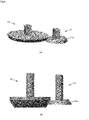
- a can 1 according to a first embodiment will be described by using Fig. 1 or Fig. 2 .
- the can 1 is formed of a publicly-known metallic material used for the can, such as steel, tinplate, aluminum, aluminum alloy, or the like, for example.
- the can 1 ordinarily has a cylindrical body 2 having an outside diameter of 45 mm ⁇ , 53 mm ⁇ , 66 mm ⁇ , or the like, a shoulder 3 which is connected to a side of an upper end of the body 2 in a can axis direction, and is reduced in a diameter toward upward (side of the mouth), and a mouth 4 which is connected to a side of an upper end of the shoulder 3 in the can axis direction, and extended upward.
- the shoulder 3 is formed into a diameter reduced portion in which the diameter is reduced from a side of the body 2 toward a side of the mouth 4.
- a flange 5 is provided at an end of the mouth 4.
- a publicly-known can lid (not shown) is seamed around the mouth 4.
- the can 1 has a chime portion 6 gradually reduced in the diameter toward downward on a side of a lower end (side of the bottom) of the body 2 of the can 1.
- An inside diameter ⁇ A of the mouth 4 can be set to 25 to 60 mm, for example.
- a maximum outside diameter ⁇ B of the shoulder 3 (namely, it is an outside diameter of a part connecting the shoulder 3 and the body 2, and it becomes the same with the outside diameter of the body 2, when a side surface of the body 2 is formed into a straight shape) can be set to 50 to 70 mm, for example.
- a three-dimensionally shaped portion area 3a shown by hatching on the shoulder 3 is provided with the three-dimensionally shaped portion.
- the three-dimensionally shaped portion has at least one of a depressed concave portion and a raised convex portion.
- depressed concave portion means a concave three-dimensional shape when viewed from an outside surface of the can, and a convex three-dimensional shape when viewed from an inside surface of the can.
- raised convex portion means a convex three-dimensional shape when viewed from the outside surface of the can, and a concave three-dimensional shape when viewed from the inside surface of the can.
- the three-dimensionally shaped portion may be provided with a plurality of depressed concave portions having a same shape at an equal interval on a whole circumference.
- the three-dimensionally shaped portion may be provided with the depressed concave portions which are different in a shape in a circumferential direction.
- a plurality of rows along a height direction of the shoulder are aligned in the circumferential direction.
- the plurality of depressed concave portions having the same shape are arranged in the different number (for example, 1 to 4).
- the shapes of the three-dimensionally shaped portions are different in the circumference of the shoulder 3.
- the three-dimensionally shaped portion may have intermittently the depressed portions in part or a plurality of parts of the shoulder 3 in the circumferential direction.
- the three-dimensionally shaped portion may have the raised convex portion in place of the depressed concave portion, or may be a mixture of the depressed concave portion and the raised convex portion.
- the three-dimensionally shaped portion may have any one of the depressed concave portion or the raised convex portion, or may have one by one, respectively.
- the shape of the depressed concave portion or the raised convex portion may be a designed shape of a geometrical pattern, a character, a sign, a person, an animal, a plant, a vehicle, an appliance, scenery, food and drink, packaged food and drink, and the like, for example.
- a depressed direction of the depressed concave portion or a raised direction of the raised convex portion can be appropriately set in consideration of appearance, a shape of the shoulder 3, a direction without interfering a moving direction of an inner roll 11 or an outer roll 12 described later, or the like.
- a ratio of the maximum outside diameter ⁇ B of the shoulder of the can 1 to the inside diameter ⁇ A of the mouth of the can 1 is preferably 1.05 to 1.58.
- Such a ratio of the diameters is set, whereby a sufficiently large width of the shoulder 3 can be secured in the can 1, and therefore a sufficiently wide three-dimensionally shaped portion area 3a can be secured.
- such a ratio is effective upon three-dimensionally shaped portion rotating processing of the shoulder 3 by clamping with the receiver 11a of the inner roll 11 and the outer roll 12 described later.
- a material as thin as 0.1 to 0.3 mm is preferable, and setting to 0.1 to 0.2 mm is more preferable.
- the wall thickness t of the shoulder is thus set, whereby three-dimensional decoration as in the three-dimensionally shaped portion can be applied to the shoulder 3 of the can 1 in which a material is reduced, and even if the three-dimensionally shaped portion is formed, a fine hole such as a pinhole is hard to be perforated.
- the three-dimensionally shaped portion can be processed, even with such a thin wall thickness of the shoulder, by three-dimensionally shaped portion rotating processing of the shoulder 3 by clamping with the receiver 11a of the inner roll 11 and the outer roll 12.
- the shoulder 3 is processed in a reduced diameter, and therefore the wall thickness of the shoulder 3 may be greater than a wall thickness of the body 2.
- the shoulder 3 has sufficient strength, and therefore formation of the pinhole or the like during processing can be further suppressed, and buckling or the like caused by external force can also be suppressed.
- the shoulder 3 is inclined as a circular truncated cone side form in a midrange in the height direction.
- An inclination angle ⁇ is set to 10° to 50° (more preferably 25° to 45°), whereby relative to the mouth 4 having a predetermined inside diameter ⁇ A of the mouth and the shoulder 3 having a predetermined maximum outside diameter ⁇ B of the shoulder, as inclination steepness of the shoulder 3 is larger (closer to vertical), a width of the shoulder 3 is increased, and a larger three-dimensionally shaped portion area 3a can be kept.
- such setting is effective upon three-dimensionally shaped portion rotating processing of the shoulder 3 by clamping with the receiver 11a of the inner roll 11 and the outer roll 12 described later.
- the inclination angle ⁇ is an angle between a surface formed by extending the shoulder 3 to the side of the body 2, and the body 2.
- such an effect can be produced as being capable of improving processability of the three-dimensionally shaped portion and the strength of the can, and capable of forming the can reduced in the diameter from the maximum outside diameter ⁇ B of the shoulder to the inside diameter ⁇ A of the mouth within the range in the height direction of the can effective to aesthetic appearance.
- a closed-end cylindrical intermediate formed body having the body 2 is manufactured by a publicly-known drawing and ironing or the like, and printing, painting or the like is applied to internal and external surfaces of the intermediate formed body, when necessary.
- a shoulder 3P is formed by performing such processing to the intermediate formed body as die necking or roll necking (spin flow necking) configured of a plurality of publicly-known processes, or a combination of the die necking or the roll necking configured of the plurality of publicly-known processes.
- the mouth 4 having the flange 5 on an opening end is formed on the intermediate formed body by a publicly-known die flanger or a spin flanger, or the like.
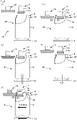
- a can 1P which is the intermediate formed body of the can 1, as shown in Fig. 3 or the like, is manufactured.
- the three-dimensionally shaped portion is formed on the shoulder 3P using a three-dimensionally shaped portion processing device 10 (or a apparatus for manufacturing the can).
- the three-dimensionally shaped portion processing device 10 has an inner roll 11 and an outer roll 12 as a tool set for manufacturing the can.
- a receiver 11a is provided at a bottom of the inner roll 11.
- a shaft 11b and the receiver 11a may be connected by screw clamping, for example.
- the receiver 11a is a part (step portion) which has the outside diameter larger than the diameter of the shaft 11b, and is provided on the inner roll 11 in a step form.
- the receiver 11a of the inner roll 11 is provided with a pattern of a concave (concave portion) or a convex (convex portion) corresponding to the three-dimensionally shaped portion in the range shown by hatching.
- the outer roll 12 is also provided with a pattern of a concave (concave portion) or a convex (convex portion) corresponding to the concave or the convex provided on the receiver 11a in the range shown by hatching.
- the concave of the receiver 11a of the inner roll 11 and the convex of the outer roll 12 corresponding to the depressed concave shape of the shoulder 3 shown in Fig. 2(a) has a form shown in Fig. 4(a) .
- the concave of the receiver 11a of the inner roll 11 and the convex of the outer roll 12 corresponding to the depressed concave shape of the shoulder 3 shown in Fig. 2(b) has a form shown in Fig. 4(b) .
- the receiver 11a of the inner roll 11 only needs to have at least one of the concave and the convex according to the shape of the shoulder 3 of the can 1. More specifically, when the shoulder 3 has the raised convex portion, the receiver 11a only needs to have the concave. When the shoulder 3 has the depressed concave portion and the raised convex portion, the receiver 11a only needs to have the concave and the convex. The same shall apply also to the concave or the convex of the outer roll 12.
- the shaft 11b serving as a rotating axis of the inner roll 11 is a solid or hollow shaft form having an outside diameter ⁇ D.
- a cylinder having ⁇ 10 mm or more is preferable in the case of the solid shaft, and a cylinder having a wall thickness of 5 mm or more is preferable in the case of the hollow shaft, in view of the strength, although the outside diameter depends on the material.
- a maximum outside diameter ⁇ E of the receiver 11a is smaller than the inside diameter ⁇ A of the mouth of the can 1P, whereby the inner roll 11 can be relatively inserted into or removed from the can 1P.
- the ratio of the maximum outside diameter ⁇ B of the shoulder to the inside diameter ⁇ A of the mouth of the can 1P is set to 1.05 to 1.58. Therefore, in the three-dimensionally shaped portion area 3a, an effective extent can be secured, and the receiver 11a of the inner roll 11 can firmly support the shoulder 3P of the can 1P. Further, the inner roll 11 can be inserted into or removed from the mouth 4, even if the shaft 11b sufficiently secures a thickness or a wall thickness in view of strength.
- An external shape of the receiver 11a of the inner roll 11 is preferably the shape along the shoulder 3P of the can 1P.
- the external shape of the receiver 11a of the inner roll 11 is formed into a bevel shape including a circular truncated cone side part along the shape of the shoulder 3P.
- the receiver 11a of the inner roll 11 can be formed into the shape closer to the shoulder 3P of the can 1P, and therefore can support the shoulder 3P of the can 1P further firmly in the rotating process described later (see Fig. 5(c) ).
- both the can 1P and the receiver 11a of the inner roll 11 have the circular truncated cone side part having a predetermined angle.
- processing force from the inner roll 11 and the outer roll 12 is further easily transmitted to the shoulder 3P, in comparison with side part having a spherical surface-like shape (shape having a convex curvature radius toward a longitudinal section outward direction) and therefore is further preferable.
- the external shape of the receiver 11a of the inner roll 11 may be the shape along the shoulder 3P of the can 1P thoroughly from the outside diameter of the shaft 11b to the maximum outer diameter part of the receiver 11a, as shown in Fig. 3 , Fig. 5(c) or the like.
- the external shape is not limited thereto, and the external shape of the receiver 11a may be the shape formed by allowing only part of the receiver 11a to align along the shoulder 3P as shown in Fig. 4(a) or Fig. 4(b) , as long as the thickness of the shaft 11b can be sufficiently secured.
- the inclination angle ⁇ of the shoulder 3 of the can 1P according to the present embodiment is set to 10° to 50°. Therefore, in the receiver 11a of the inner roll 11, an effective extent for processing the three-dimensionally shaped portion area 3a can be secured. Moreover, the inner roll 11 can be inserted into or removed from the mouth 4 even if the shaft 11b sufficiently secures the thickness or the wall thickness in view of the strength.
- the inclination of the shoulder 3 in a normal direction is not excessively steep relative to the direction (the radial direction of the can 1P) in which processing forming force of the can 1P works, and therefore the processing forming force is easily transmitted to the shoulder 3.
- angle ⁇ between the surface formed by extending the shaft 11b to a side of the receiver 11a, and the side surface of the receiver 11a is the same with the angle between the surface formed by extending the above-described shoulder 3 to the side of the body 2, and the body 2.
- An external shape of the outer roll 12 only needs to correspond to the receiver 11a of the inner roll 11, and formed into the shape capable of uneven rotating processing.
- the inner roll 11 and the outer roll 12 are formed into the bevel shape upside down with each other.
- a ratio of an outside diameter ⁇ 11a, in a center in the height direction, of the three-dimensionally shaped portion (hatched range), of the receiver 11a of the inner roll 11 to an outside diameter ⁇ G, in the center in the height range, of the three-dimensionally shaped portion of the shoulder 3P of the can 1P may be appropriately set to a smaller ratio (for example, approximately 4/5); however, it is preferably set to the ratio close to "1/natural number of 2 or more", and is set to approximately 1/2 in the present embodiment.
- an outside diameter ⁇ F of the three-dimensionally processing formed portion (hatched range) of the outer roll 12 in the center in the height direction may be arbitrarily adjusted to be larger than the outside diameter ⁇ G, as long as the outer roll 12 can respond to unevenness of the receiver 11a of the inner roll 11.
- the three-dimensionally shaped portion processing device 10 is equipped with a placing table 13 capable of placing the can 1P thereon, rotating with the can 1P and advancing or retracting the can 1P to or from a position before processing and a processing position.
- a rotating axis of the placing table 13 and the rotating axis of the inner roll 11 are in parallel to each other.
- a direction of a rotating axis of the outer roll 12 is not particularly limited as long as the outer roll 12 can follow the inner roll 11 or the shoulder 3P.
- each rotating axis of the placing table 13, the inner roll 11, and the outer roll 12 is arranged to be in parallel to each other.
- a rotational speed when the placing table 13 rotates to process the shoulder 3P of the can 1P is preferably 10 to 300 rpm in the case of low speed, and preferably 300 to 700 rpm in the case of high speed, although the rotational speed depends on the shape of the three-dimensionally shaped portion, a material of the can 1P, and other conditions.
- the rotational speed in the case of low speed, is set at 30 rpm, and in the case of high speed, the rotational speed is set at 400 rpm.
- the rotational speeds of the inner roll 11 and the outer roll 12 are, in view a relationship of a ratio of ⁇ 11a, ⁇ F, and ⁇ G, set to 60 rpm and 30 rpm in the case of low speed, respectively, and are set to 800 rpm and 400 rpm in the case of high speed, respectively, in the present embodiment.
- the inner roll 11 or the outer roll 12 is rotated by a rotating drive unit (rotating unit) of the three-dimensionally shaped portion processing device 10.
- the can 1P is placed on the placing table 13 by a conveyor (not shown).
- the placing table 13 is allowed to move to move the can 1P to the processing position.
- the inner roll 11 is inserted into the can 1P from the mouth 4.
- the shoulder 3P is clamped by the receiver 11a and the outer roll 12 by allowing the inner roll 11 and the outer roll 12 to relatively come close to the shoulder 3P of the can 1P. More specifically, the receiver 11a receives the shoulder 3P from inside, and on the other hand, the outer roll 12 presses the shoulder 3P from outside.
- the inner roll 11 and the outer roll 12 moves in the radial direction of the can 1P; however, without being limited thereto, the rolls may move along the direction according to a depressed direction of the concave portion of the three-dimensionally shaped portion, the raised direction of the convex portion, or the like.
- the shoulder 3P is processed by the receiver 11a of the inner roll 11 and the outer roll 12
- interference can be prevented between parts forming concave or convex patterns on the three-dimensionally shaped portion, or parts forming the concave or convex patterns on the receiver 11a of the inner roll 11, parts forming the concave or convex patterns on the outer roll 12, or the like.
- both may be moved along the direction depending on the depressed direction of the concave portion or the raised direction of the convex portion of the three-dimensionally shaped portion.
- the inner roll 11 and the outer roll 12 are rotated to integrally rotate the placing table 13 and the can 1P. Then, the can 1P rotates by a predetermined amount (for example, one rotation or more) to form the three-dimensionally shaped portion in the three-dimensionally shaped portion area 3a.
- the shoulder 3P is rotatingly processed in a state of being clamped to the inner roll 11 and the outer roll 12, while the shoulder 3P is reliably supported by the receiver 11a of the inner roll 11 from inside. Therefore, the shoulder 3P is hard to cause abnormal deformation, damage or the like, even if the shoulder 3P of the can 1P is thin-walled.
- the can 1P is relatively separated from the processing position by moving the placing table 13. As a result, the can 1P is retracted from the processing position.
- the inner roll 11 and the outer roll 12 move toward the side of the mouth 4 in the height direction to move relatively to the can 1P.
- the inner roll 11 moves to an outside of the can 1P from the mouth 4.
- the three-dimensional shape is formed on the shoulder 3P while the receiver 11a of the inner roll 11 receives the shoulder 3P from inside, damage onto the shoulder 3P can be suppressed.
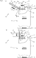
- each roll in the three-dimensionally shaped portion processing device according to the first embodiment is changed as described below.
- the rotating axis 12c of the outer roll 12 is not in parallel to the rotating axis of the inner roll 11 or the placing table 13, and is arranged to be in a crossed or twisted position. More specifically, the rotating axis 12c of the outer roll 12 and the rotating axis 11c of the inner roll 11 are in different directions, and not in parallel to each other.
- a processing portion of the outer roll 12 shown in Fig. 6(a) is a columnar member, and not in a circular truncated cone shape as in the first embodiment.
- the rotating axis 12c of the outer roll 12 and an inclined surface of the shoulder 3P are in parallel to each other. Therefore, the rotating axis 12c of the outer roll 12 and the rotating axis 11c of the inner roll 11 are crossed at the inclination angle ⁇ .
- a circumferential surface of the outer roll 12 is vertically pressed onto an outer surface of the shoulder 3P (see an arrow A12). Therefore, the circumferential surface of the outer roll 12 and the receiver 11a of the inner roll 11 can clamp the shoulder 3P with strong force. Thus, the outer roll 12 and the inner roll 11 can cause improvement in shapability onto the three-dimensionally shaped portion area 3a.
- the outer roll 12 in Fig. 6(b) has a circular truncated cone shape diameter reduced portion 12a having a shape corresponding to the receiver 11a of the inner roll 11. Moreover, the rotating axis 12c of the outer roll 12 is perpendicular to the rotating axis 11c of the inner roll 11 (see an angle ⁇ 12). Thus, the inner roll 11 and the outer roll 12 rotate in a bevel gear form in a state of pressing the shoulder 3P from inside and outside.
- both circumferential speeds in a part in which both clamp the shoulder 3P can be adjusted to an equivalent level or a difference between both the circumferential speeds can be reduced.
- friction between the shoulder 3P and the inner roll 11 and between the shoulder 3P and the outer roll 12 can be reduced, and therefore the damage or the like onto the shoulder 3P during processing can be suppressed.
- a degree of freedom of setting a direction of the rotating axis 11c or 12c of the inner roll 11 or the outer roll 12 can be increased.
- the can 1P may be a material after forming the shoulder 3P and before forming the flange 5.
- the shoulder 3P may be widened or expanded to an inside by further reducing the diameter of the mouth 4, whereby the can 1 may be formed into the can having a reduced diameter.
- the can 1P in Fig. 7 has a three-dimensionally shaped portion area 2a also on the body 2, in addition to the shoulder 3P.
- the inner roll 11 is provided with a body inner pressing portion 11d from the receiver 11a toward a downside.
- the body inner pressing portion 11d is a cylindrical member.
- the body inner pressing portion 11d has, in the range shown by hatching on a circumferential surface thereof, at least one of a concave portion and a convex portion having a shape corresponding to the three-dimensionally shaped portion of the three-dimensionally shaped portion area 2a, in a manner similar to the receiver 11a.
- the outer roll 12 is provided with a body outer pressing portion 12d from a circular truncated cone part toward the downside.
- the body outer pressing portion 12d is a cylindrical member.
- the body outer pressing portion 12d has, in the range shown by hatching on the circumferential surface thereof, at least one of a concave portion and a convex portion having a shape corresponding to the body inner pressing portion 11d.
- the body inner pressing portion 11d and the body outer pressing portion 12d clamp the body 2 from outside and inside.
- the body inner pressing portion 11d presses the body 2 from inside
- the body outer pressing portion 12d presses the body 2 from outside.
- the inner roll 11 and the outer roll 12 rotate relative to the can 1P, whereby the inner roll 11 and the outer roll 12 can simultaneously form the three-dimensionally shaped portion on the three-dimensionally shaped portion areas 2a and 3a of the body 2 and the shoulder 3P, respectively.
- the inner roll 11 and the outer roll 12 as shown in Fig. 7 can cause decoration of the body 2 and the shoulder 3P of the can 1P within the same process.
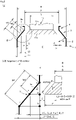
- Fig. 8(a) is an explanatory diagram schematically showing a cross-sectional view of an upper part of the can 1, and schematically showing the inner roll 11.
- Fig. 8(b) shows an enlarged view of B portion in Fig. 8(a) .
- the receiver 11a of the inner roll 11 in Fig. 8 has a most simple configuration, and formed only of a part corresponding to the three-dimensionally shaped portion area 3a of the can 1. Therefore, the circular truncated cone side surface of the receiver 11a is wholly in the range in which the convex or the concave corresponding to the three-dimensionally shaped portion of the three-dimensionally shaped portion area 3a can be formed.
- a thickness of the can 1 is not taken into consideration. If the thickness thereof is taken into consideration, the thickness can be appropriately set as "B: maximum outside diameter of the shoulder 3 of the can 1" and "A: inside diameter of the mouth 4 of the can 1", or the like.
- a radial length corresponding to each of the length W1 and W2 is a length L1 of a side bc of a triangle abc and a length L2 of a side de of a triangle ade, and the length L1 can be represented by the following formula.
- L 1 B ⁇ A / 2
- a protrusion length L3 of the receiver 11a is equal to the length L2 in the radial direction.
- L2 L 3
- L 2 A ⁇ 2 ⁇ C ⁇ D / 2
- the clearance C (mm) preferably satisfies a formula: "1 ⁇ C" in consideration of actual processability.
- the shaft diameter D (mm) preferably satisfies a formula: "10 ⁇ D”. Then, with respect to Formula 1, the following relational formula holds. 12 ⁇ A ⁇ B ⁇ A ⁇ W 2 / W 1
- the can 1 satisfying Formula 2 produces an effect of favorable processability because a sufficient clearance for inserting or removing the inner roll 12 into or from the mouth 4, and the strength of the shaft 11b can be sufficiently secured.
- the can 1 in which Formula 2 and a formula: "W2/W1 ⁇ 0.5" hold produces, in addition to the above-described effect, an effect of being capable of arranging the three-dimensionally shaped portion area 3a in a part up to a half of the shoulder 3 in the range from the root on the side of the mouth 4 of the shoulder 3 toward the side of the body 2.
- the can 1 in which Formula 2 and a formula: "W2/W1 ⁇ 1" hold produces, in addition to the above-described effect, an effect of being capable of arranging the three-dimensionally shaped portion area 3a in the whole range of the shoulder 3.
- a length W3 of an inclined surface of the circular truncated cone side surface of the receiver 11a is equal to the three-dimensionally shaped portion mountable length W2.
- the protrusion length L3 of the receiver 11a can be represented by the following formula.
- a receiver outside diameter E can be represented by the following formula.
- E D + 2 ⁇ L 3
- E D + 2 ⁇ W 2 ⁇ sin ⁇
- the inner roll 11 produces an effect of being capable of processing the shoulder 3 of the can 1 because the inner roll 11 can be inserted into or removed from the mouth 4 by satisfying Formula 3.
- the clearance C (mm) preferably satisfies the formula: 1 ⁇ C as described above. Therefore, in the inner roll 11, processability can be improved by satisfying the formula: 1 ⁇ C, in addition to Formula 3.
Landscapes
- Engineering & Computer Science (AREA)
- Mechanical Engineering (AREA)
- Ceramic Engineering (AREA)
- Containers Having Bodies Formed In One Piece (AREA)
- Shaping Metal By Deep-Drawing, Or The Like (AREA)
- Massaging Devices (AREA)
- Seasonings (AREA)
- Jellies, Jams, And Syrups (AREA)
- Light Receiving Elements (AREA)
Priority Applications (1)
| Application Number | Priority Date | Filing Date | Title |
|---|---|---|---|
| EP25181818.3A EP4592210A3 (de) | 2017-07-31 | 2018-07-31 | Dosenherstellungsvorrichtung, dose und dosenherstellungswerkzeugsatz |
Applications Claiming Priority (4)
| Application Number | Priority Date | Filing Date | Title |
|---|---|---|---|
| JP2017148630 | 2017-07-31 | ||
| JP2017177917A JP6662363B2 (ja) | 2017-07-31 | 2017-09-15 | 缶製造方法、缶の肩部に立体成形部を形成する装置、缶、缶製造工具セット |
| PCT/JP2018/028631 WO2019026898A1 (ja) | 2017-07-31 | 2018-07-31 | 缶製造方法、缶製造装置、缶、缶製造工具セット |
| EP18840891.8A EP3663013B1 (de) | 2017-07-31 | 2018-07-31 | Verfahren zur herstellung einer dose |
Related Parent Applications (2)
| Application Number | Title | Priority Date | Filing Date |
|---|---|---|---|
| EP18840891.8A Division EP3663013B1 (de) | 2017-07-31 | 2018-07-31 | Verfahren zur herstellung einer dose |
| EP18840891.8A Division-Into EP3663013B1 (de) | 2017-07-31 | 2018-07-31 | Verfahren zur herstellung einer dose |
Related Child Applications (1)
| Application Number | Title | Priority Date | Filing Date |
|---|---|---|---|
| EP25181818.3A Division EP4592210A3 (de) | 2017-07-31 | 2018-07-31 | Dosenherstellungsvorrichtung, dose und dosenherstellungswerkzeugsatz |
Publications (2)
| Publication Number | Publication Date |
|---|---|
| EP4035792A2 true EP4035792A2 (de) | 2022-08-03 |
| EP4035792A3 EP4035792A3 (de) | 2022-11-02 |
Family
ID=65232684
Family Applications (2)
| Application Number | Title | Priority Date | Filing Date |
|---|---|---|---|
| EP22161965.3A Pending EP4035792A3 (de) | 2017-07-31 | 2018-07-31 | Vorrichtung zur herstellung einer dose, dose und werkzeugsatz zur herstellung einer dose |
| EP25181818.3A Pending EP4592210A3 (de) | 2017-07-31 | 2018-07-31 | Dosenherstellungsvorrichtung, dose und dosenherstellungswerkzeugsatz |
Family Applications After (1)
| Application Number | Title | Priority Date | Filing Date |
|---|---|---|---|
| EP25181818.3A Pending EP4592210A3 (de) | 2017-07-31 | 2018-07-31 | Dosenherstellungsvorrichtung, dose und dosenherstellungswerkzeugsatz |
Country Status (4)
| Country | Link |
|---|---|
| EP (2) | EP4035792A3 (de) |
| CN (2) | CN114194556B (de) |
| ES (1) | ES2951558T3 (de) |
| WO (1) | WO2019026898A1 (de) |
Families Citing this family (2)
| Publication number | Priority date | Publication date | Assignee | Title |
|---|---|---|---|---|
| CN114178370A (zh) * | 2021-11-08 | 2022-03-15 | 苏州华源中鲈包装有限公司 | 一种用于罐体的刻筋结构 |
| JP7835549B2 (ja) * | 2021-11-09 | 2026-03-25 | 東洋製罐グループホールディングス株式会社 | 樹脂被覆アルミ合金製絞りしごき缶 |
Citations (8)
| Publication number | Priority date | Publication date | Assignee | Title |
|---|---|---|---|---|
| EP0377985A1 (de) | 1989-01-09 | 1990-07-18 | Cmb Foodcan Plc | Herstellung von Dosenkörpern |
| JP2003340539A (ja) | 2003-07-04 | 2003-12-02 | Toyo Seikan Kaisha Ltd | エンボス加工缶体の製造方法 |
| JP2004123231A (ja) | 2002-08-06 | 2004-04-22 | Mitsubishi Materials Corp | ボトル缶並びに金型及びボトル缶製造装置及びその製造方法 |
| JP2004168346A (ja) | 2002-11-19 | 2004-06-17 | Daiwa Can Co Ltd | 肩部にまで印刷模様が施された缶体の製造方法 |
| JP2011005512A (ja) | 2009-06-24 | 2011-01-13 | Toyo Seikan Kaisha Ltd | エンボス加工装置、エンボス加工方法、及び、エンボス缶 |
| CN103803145A (zh) | 2014-01-27 | 2014-05-21 | 广东欧亚包装有限公司 | 一种铝质变壁异形包装罐及其制造方法 |
| EP2835188A1 (de) | 2012-03-27 | 2015-02-11 | Universal Can Corporation | Verfahren und vorrichtung zur herstellung einer flaschendose mit gewinde |
| US20150360279A1 (en) | 2014-06-12 | 2015-12-17 | Ball Corporation | System for compression relief shaping |
Family Cites Families (17)
| Publication number | Priority date | Publication date | Assignee | Title |
|---|---|---|---|---|
| US1463073A (en) * | 1922-03-11 | 1923-07-24 | New England Metal Barrel Corp | Machine for shaping cylinders |
| JPH0411487Y2 (de) * | 1986-04-04 | 1992-03-23 | ||
| JPH084862B2 (ja) * | 1986-10-27 | 1996-01-24 | 武内プレス工業株式会社 | スムーズネックイン缶の製法および該方法に用いる装置 |
| JPH07102417B2 (ja) * | 1989-08-31 | 1995-11-08 | 東洋製罐株式会社 | 缶詰用缶及びその製造方法 |
| JPH0359686U (de) * | 1989-10-13 | 1991-06-12 | ||
| US5645190A (en) * | 1995-09-29 | 1997-07-08 | Goldberg; Norton Robert | Aluminum beverage can |
| JP3610653B2 (ja) * | 1995-12-26 | 2005-01-19 | 株式会社デンソー | 金属パイプの溝加工方法及び溝加工装置 |
| US5761942A (en) * | 1996-07-19 | 1998-06-09 | Aluminum Company Of America | Apparatus and method for the embossing of containers |
| GB9623364D0 (en) * | 1996-11-09 | 1997-01-08 | Metal Box Plc | Reshaping of drawn and wall ironed containers |
| JP2002256366A (ja) * | 2001-02-27 | 2002-09-11 | Kobe Steel Ltd | ボトル缶用アルミニウム板 |
| WO2006043347A1 (ja) * | 2004-10-20 | 2006-04-27 | Universal Can Corporation | ボトル缶の製造方法およびボトル缶 |
| JP2008126264A (ja) * | 2006-11-21 | 2008-06-05 | Kirin Brewery Co Ltd | 缶胴加工装置、その内側ロール及び外側ロール並びに凹凸加工された金属缶の製造方法 |
| US8297072B2 (en) * | 2007-10-16 | 2012-10-30 | Millercoors, Llc | Container incorporating integral cooling element |
| JP5483963B2 (ja) * | 2009-09-07 | 2014-05-07 | サントリーホールディングス株式会社 | 金属缶本体および金属缶 |
| CN101708525A (zh) * | 2009-09-23 | 2010-05-19 | 太平洋制罐(北京)有限公司 | 铝制两片易拉罐的铝材减薄方法及铝制两片易拉罐 |
| CN201553354U (zh) * | 2009-09-24 | 2010-08-18 | 太平洋制罐(北京)有限公司 | 500ml容量铝制两片易拉罐 |
| CN204776466U (zh) * | 2014-05-30 | 2015-11-18 | 环宇制罐株式会社 | 饮料罐 |
-
2018
- 2018-07-31 ES ES18840891T patent/ES2951558T3/es active Active
- 2018-07-31 CN CN202111514460.2A patent/CN114194556B/zh active Active
- 2018-07-31 WO PCT/JP2018/028631 patent/WO2019026898A1/ja not_active Ceased
- 2018-07-31 EP EP22161965.3A patent/EP4035792A3/de active Pending
- 2018-07-31 CN CN201880049783.9A patent/CN110997174B/zh active Active
- 2018-07-31 EP EP25181818.3A patent/EP4592210A3/de active Pending
Patent Citations (8)
| Publication number | Priority date | Publication date | Assignee | Title |
|---|---|---|---|---|
| EP0377985A1 (de) | 1989-01-09 | 1990-07-18 | Cmb Foodcan Plc | Herstellung von Dosenkörpern |
| JP2004123231A (ja) | 2002-08-06 | 2004-04-22 | Mitsubishi Materials Corp | ボトル缶並びに金型及びボトル缶製造装置及びその製造方法 |
| JP2004168346A (ja) | 2002-11-19 | 2004-06-17 | Daiwa Can Co Ltd | 肩部にまで印刷模様が施された缶体の製造方法 |
| JP2003340539A (ja) | 2003-07-04 | 2003-12-02 | Toyo Seikan Kaisha Ltd | エンボス加工缶体の製造方法 |
| JP2011005512A (ja) | 2009-06-24 | 2011-01-13 | Toyo Seikan Kaisha Ltd | エンボス加工装置、エンボス加工方法、及び、エンボス缶 |
| EP2835188A1 (de) | 2012-03-27 | 2015-02-11 | Universal Can Corporation | Verfahren und vorrichtung zur herstellung einer flaschendose mit gewinde |
| CN103803145A (zh) | 2014-01-27 | 2014-05-21 | 广东欧亚包装有限公司 | 一种铝质变壁异形包装罐及其制造方法 |
| US20150360279A1 (en) | 2014-06-12 | 2015-12-17 | Ball Corporation | System for compression relief shaping |
Also Published As
| Publication number | Publication date |
|---|---|
| CN110997174B (zh) | 2021-12-14 |
| WO2019026898A1 (ja) | 2019-02-07 |
| EP4035792A3 (de) | 2022-11-02 |
| CN114194556B (zh) | 2024-02-13 |
| EP4592210A2 (de) | 2025-07-30 |
| CN114194556A (zh) | 2022-03-18 |
| ES2951558T3 (es) | 2023-10-23 |
| EP4592210A3 (de) | 2025-10-08 |
| CN110997174A (zh) | 2020-04-10 |
Similar Documents
| Publication | Publication Date | Title |
|---|---|---|
| EP3663013B1 (de) | Verfahren zur herstellung einer dose | |
| CA2169743C (en) | Method of forming a metal container body | |
| KR101388292B1 (ko) | 미가공 메탈 피스 상에서 복잡한 구조를 가진 에지 또는 칼라 제조 공정 및 장치 | |
| WO2016192397A1 (en) | Irregular aluminum cup and method for manufacturing the same | |
| US5209099A (en) | Draw-process methods, systems and tooling for fabricating one-piece can bodies | |
| WO2006043347A1 (ja) | ボトル缶の製造方法およびボトル缶 | |
| US11858681B2 (en) | Can body and method of manufacturing thereof | |
| EP2859965B1 (de) | Tiefzugformungsverfahren und umformwerkzeug dafür | |
| EP4035792A2 (de) | Vorrichtung zur herstellung einer dose, dose und werkzeugsatz zur herstellung einer dose | |
| JPS6338020Y2 (de) | ||
| ES2903202T3 (es) | Un método para conformar un tapón de cierre de embutición profunda | |
| TWI788515B (zh) | 罐子製造方法、罐子製造裝置、罐子以及罐子製造工具組 | |
| JP4607690B2 (ja) | 絞り/しごき成形装置および成形方法 | |
| JP2025537564A (ja) | エアゾールドームの製造方法 | |
| JPH11169979A (ja) | アルミニウムdi缶の加工方法 | |
| PL90302B1 (de) |
Legal Events
| Date | Code | Title | Description |
|---|---|---|---|
| PUAI | Public reference made under article 153(3) epc to a published international application that has entered the european phase |
Free format text: ORIGINAL CODE: 0009012 |
|
| STAA | Information on the status of an ep patent application or granted ep patent |
Free format text: STATUS: THE APPLICATION HAS BEEN PUBLISHED |
|
| AC | Divisional application: reference to earlier application |
Ref document number: 3663013 Country of ref document: EP Kind code of ref document: P |
|
| AK | Designated contracting states |
Kind code of ref document: A2 Designated state(s): AL AT BE BG CH CY CZ DE DK EE ES FI FR GB GR HR HU IE IS IT LI LT LU LV MC MK MT NL NO PL PT RO RS SE SI SK SM TR |
|
| PUAL | Search report despatched |
Free format text: ORIGINAL CODE: 0009013 |
|
| AK | Designated contracting states |
Kind code of ref document: A3 Designated state(s): AL AT BE BG CH CY CZ DE DK EE ES FI FR GB GR HR HU IE IS IT LI LT LU LV MC MK MT NL NO PL PT RO RS SE SI SK SM TR |
|
| RIC1 | Information provided on ipc code assigned before grant |
Ipc: B65D 8/04 20060101ALI20220928BHEP Ipc: B21D 51/38 20060101ALI20220928BHEP Ipc: B21D 22/08 20060101ALI20220928BHEP Ipc: B21D 22/02 20060101ALI20220928BHEP Ipc: B21D 17/04 20060101ALI20220928BHEP Ipc: B21D 51/26 20060101AFI20220928BHEP |
|
| STAA | Information on the status of an ep patent application or granted ep patent |
Free format text: STATUS: REQUEST FOR EXAMINATION WAS MADE |
|
| 17P | Request for examination filed |
Effective date: 20230421 |
|
| RBV | Designated contracting states (corrected) |
Designated state(s): AL AT BE BG CH CY CZ DE DK EE ES FI FR GB GR HR HU IE IS IT LI LT LU LV MC MK MT NL NO PL PT RO RS SE SI SK SM TR |
|
| STAA | Information on the status of an ep patent application or granted ep patent |
Free format text: STATUS: EXAMINATION IS IN PROGRESS |
|
| 17Q | First examination report despatched |
Effective date: 20250319 |