EP4033531B1 - Procédé de fabrication d'une pluralité d'îlots semiconducteurs cristallins - Google Patents
Procédé de fabrication d'une pluralité d'îlots semiconducteurs cristallins Download PDFInfo
- Publication number
- EP4033531B1 EP4033531B1 EP22161925.7A EP22161925A EP4033531B1 EP 4033531 B1 EP4033531 B1 EP 4033531B1 EP 22161925 A EP22161925 A EP 22161925A EP 4033531 B1 EP4033531 B1 EP 4033531B1
- Authority
- EP
- European Patent Office
- Prior art keywords
- islands
- layer
- group
- relaxation
- substrate
- Prior art date
- Legal status (The legal status is an assumption and is not a legal conclusion. Google has not performed a legal analysis and makes no representation as to the accuracy of the status listed.)
- Active
Links
- 238000004519 manufacturing process Methods 0.000 title claims description 58
- 238000000034 method Methods 0.000 title claims description 54
- 239000004065 semiconductor Substances 0.000 title claims description 24
- 239000000758 substrate Substances 0.000 claims description 147
- 229910052738 indium Inorganic materials 0.000 claims description 26
- APFVFJFRJDLVQX-UHFFFAOYSA-N indium atom Chemical group [In] APFVFJFRJDLVQX-UHFFFAOYSA-N 0.000 claims description 26
- 230000005693 optoelectronics Effects 0.000 claims description 15
- 239000001963 growth medium Substances 0.000 claims description 12
- 239000007789 gas Substances 0.000 claims description 9
- 239000002243 precursor Substances 0.000 claims description 9
- QGZKDVFQNNGYKY-UHFFFAOYSA-N Ammonia Chemical compound N QGZKDVFQNNGYKY-UHFFFAOYSA-N 0.000 claims description 8
- 239000000203 mixture Substances 0.000 claims description 4
- 229910021529 ammonia Inorganic materials 0.000 claims description 2
- 239000010410 layer Substances 0.000 description 275
- VYPSYNLAJGMNEJ-UHFFFAOYSA-N Silicium dioxide Chemical compound O=[Si]=O VYPSYNLAJGMNEJ-UHFFFAOYSA-N 0.000 description 36
- 238000011282 treatment Methods 0.000 description 33
- 239000000463 material Substances 0.000 description 32
- 230000035882 stress Effects 0.000 description 28
- 238000010438 heat treatment Methods 0.000 description 23
- 229910002601 GaN Inorganic materials 0.000 description 19
- 238000012546 transfer Methods 0.000 description 19
- 230000015572 biosynthetic process Effects 0.000 description 17
- 230000008569 process Effects 0.000 description 16
- 235000012239 silicon dioxide Nutrition 0.000 description 16
- 239000000377 silicon dioxide Substances 0.000 description 16
- 230000005855 radiation Effects 0.000 description 15
- 229910052594 sapphire Inorganic materials 0.000 description 15
- 239000010980 sapphire Substances 0.000 description 15
- 239000011159 matrix material Substances 0.000 description 13
- 238000005516 engineering process Methods 0.000 description 12
- OAICVXFJPJFONN-UHFFFAOYSA-N Phosphorus Chemical compound [P] OAICVXFJPJFONN-UHFFFAOYSA-N 0.000 description 10
- 229910052581 Si3N4 Inorganic materials 0.000 description 10
- 238000005530 etching Methods 0.000 description 10
- HQVNEWCFYHHQES-UHFFFAOYSA-N silicon nitride Chemical compound N12[Si]34N5[Si]62N3[Si]51N64 HQVNEWCFYHHQES-UHFFFAOYSA-N 0.000 description 10
- 229910052698 phosphorus Inorganic materials 0.000 description 9
- 239000011574 phosphorus Substances 0.000 description 9
- ZOXJGFHDIHLPTG-UHFFFAOYSA-N Boron Chemical compound [B] ZOXJGFHDIHLPTG-UHFFFAOYSA-N 0.000 description 8
- 229910052796 boron Inorganic materials 0.000 description 8
- 239000005380 borophosphosilicate glass Substances 0.000 description 7
- 230000001747 exhibiting effect Effects 0.000 description 7
- 150000004767 nitrides Chemical class 0.000 description 7
- 239000003351 stiffener Substances 0.000 description 7
- 238000000151 deposition Methods 0.000 description 6
- 230000008021 deposition Effects 0.000 description 6
- 238000009826 distribution Methods 0.000 description 6
- 230000000873 masking effect Effects 0.000 description 6
- XUIMIQQOPSSXEZ-UHFFFAOYSA-N Silicon Chemical compound [Si] XUIMIQQOPSSXEZ-UHFFFAOYSA-N 0.000 description 5
- 238000006243 chemical reaction Methods 0.000 description 5
- 239000003086 colorant Substances 0.000 description 5
- 230000009477 glass transition Effects 0.000 description 5
- 238000010348 incorporation Methods 0.000 description 5
- 238000002360 preparation method Methods 0.000 description 5
- 229910052710 silicon Inorganic materials 0.000 description 5
- 239000010703 silicon Substances 0.000 description 5
- 230000008030 elimination Effects 0.000 description 4
- 238000003379 elimination reaction Methods 0.000 description 4
- 229910052814 silicon oxide Inorganic materials 0.000 description 4
- JMASRVWKEDWRBT-UHFFFAOYSA-N Gallium nitride Chemical compound [Ga]#N JMASRVWKEDWRBT-UHFFFAOYSA-N 0.000 description 3
- 230000008901 benefit Effects 0.000 description 3
- 238000000407 epitaxy Methods 0.000 description 3
- 230000036961 partial effect Effects 0.000 description 3
- RGGPNXQUMRMPRA-UHFFFAOYSA-N triethylgallium Chemical compound CC[Ga](CC)CC RGGPNXQUMRMPRA-UHFFFAOYSA-N 0.000 description 3
- IBEFSUTVZWZJEL-UHFFFAOYSA-N trimethylindium Chemical compound C[In](C)C IBEFSUTVZWZJEL-UHFFFAOYSA-N 0.000 description 3
- 229910002704 AlGaN Inorganic materials 0.000 description 2
- 239000012790 adhesive layer Substances 0.000 description 2
- 230000032683 aging Effects 0.000 description 2
- 238000013459 approach Methods 0.000 description 2
- 238000003491 array Methods 0.000 description 2
- 230000000295 complement effect Effects 0.000 description 2
- 230000001419 dependent effect Effects 0.000 description 2
- 238000013461 design Methods 0.000 description 2
- 238000001312 dry etching Methods 0.000 description 2
- 230000000694 effects Effects 0.000 description 2
- 229910052733 gallium Inorganic materials 0.000 description 2
- 238000002513 implantation Methods 0.000 description 2
- 238000003780 insertion Methods 0.000 description 2
- 230000037431 insertion Effects 0.000 description 2
- 230000000670 limiting effect Effects 0.000 description 2
- 229910000069 nitrogen hydride Inorganic materials 0.000 description 2
- 230000003287 optical effect Effects 0.000 description 2
- 238000000206 photolithography Methods 0.000 description 2
- 230000007704 transition Effects 0.000 description 2
- 238000000927 vapour-phase epitaxy Methods 0.000 description 2
- 230000003313 weakening effect Effects 0.000 description 2
- CURLTUGMZLYLDI-UHFFFAOYSA-N Carbon dioxide Chemical compound O=C=O CURLTUGMZLYLDI-UHFFFAOYSA-N 0.000 description 1
- GYHNNYVSQQEPJS-UHFFFAOYSA-N Gallium Chemical compound [Ga] GYHNNYVSQQEPJS-UHFFFAOYSA-N 0.000 description 1
- UFHFLCQGNIYNRP-UHFFFAOYSA-N Hydrogen Chemical compound [H][H] UFHFLCQGNIYNRP-UHFFFAOYSA-N 0.000 description 1
- 229910001199 N alloy Inorganic materials 0.000 description 1
- 229910000577 Silicon-germanium Inorganic materials 0.000 description 1
- 230000003679 aging effect Effects 0.000 description 1
- 229910052782 aluminium Inorganic materials 0.000 description 1
- XAGFODPZIPBFFR-UHFFFAOYSA-N aluminium Chemical compound [Al] XAGFODPZIPBFFR-UHFFFAOYSA-N 0.000 description 1
- 230000005587 bubbling Effects 0.000 description 1
- 229910002090 carbon oxide Inorganic materials 0.000 description 1
- 230000008859 change Effects 0.000 description 1
- 238000003486 chemical etching Methods 0.000 description 1
- 238000000576 coating method Methods 0.000 description 1
- 230000006835 compression Effects 0.000 description 1
- 238000007906 compression Methods 0.000 description 1
- 239000000470 constituent Substances 0.000 description 1
- 230000008602 contraction Effects 0.000 description 1
- 239000013078 crystal Substances 0.000 description 1
- 238000001514 detection method Methods 0.000 description 1
- 239000002019 doping agent Substances 0.000 description 1
- 229910052734 helium Inorganic materials 0.000 description 1
- 239000001307 helium Substances 0.000 description 1
- SWQJXJOGLNCZEY-UHFFFAOYSA-N helium atom Chemical compound [He] SWQJXJOGLNCZEY-UHFFFAOYSA-N 0.000 description 1
- 239000001257 hydrogen Substances 0.000 description 1
- 229910052739 hydrogen Inorganic materials 0.000 description 1
- 238000005286 illumination Methods 0.000 description 1
- 150000002500 ions Chemical class 0.000 description 1
- 238000002955 isolation Methods 0.000 description 1
- 229910052751 metal Inorganic materials 0.000 description 1
- 239000002184 metal Substances 0.000 description 1
- 238000004806 packaging method and process Methods 0.000 description 1
- 238000005498 polishing Methods 0.000 description 1
- 238000012545 processing Methods 0.000 description 1
- 230000009467 reduction Effects 0.000 description 1
- 230000002829 reductive effect Effects 0.000 description 1
- 239000011347 resin Substances 0.000 description 1
- 229920005989 resin Polymers 0.000 description 1
- 230000000284 resting effect Effects 0.000 description 1
- 230000002441 reversible effect Effects 0.000 description 1
- HBMJWWWQQXIZIP-UHFFFAOYSA-N silicon carbide Chemical compound [Si+]#[C-] HBMJWWWQQXIZIP-UHFFFAOYSA-N 0.000 description 1
- 229910010271 silicon carbide Inorganic materials 0.000 description 1
- 239000002356 single layer Substances 0.000 description 1
- 238000001179 sorption measurement Methods 0.000 description 1
- 239000000126 substance Substances 0.000 description 1
- 230000001629 suppression Effects 0.000 description 1
- 238000007669 thermal treatment Methods 0.000 description 1
- 229910052984 zinc sulfide Inorganic materials 0.000 description 1
Images


Classifications
-
- H—ELECTRICITY
- H01—ELECTRIC ELEMENTS
- H01L—SEMICONDUCTOR DEVICES NOT COVERED BY CLASS H10
- H01L33/00—Semiconductor devices having potential barriers specially adapted for light emission; Processes or apparatus specially adapted for the manufacture or treatment thereof or of parts thereof; Details thereof
- H01L33/005—Processes
- H01L33/0062—Processes for devices with an active region comprising only III-V compounds
- H01L33/0066—Processes for devices with an active region comprising only III-V compounds with a substrate not being a III-V compound
- H01L33/007—Processes for devices with an active region comprising only III-V compounds with a substrate not being a III-V compound comprising nitride compounds
-
- H—ELECTRICITY
- H01—ELECTRIC ELEMENTS
- H01L—SEMICONDUCTOR DEVICES NOT COVERED BY CLASS H10
- H01L25/00—Assemblies consisting of a plurality of individual semiconductor or other solid state devices ; Multistep manufacturing processes thereof
- H01L25/03—Assemblies consisting of a plurality of individual semiconductor or other solid state devices ; Multistep manufacturing processes thereof all the devices being of a type provided for in the same subgroup of groups H01L27/00 - H01L33/00, or in a single subclass of H10K, H10N, e.g. assemblies of rectifier diodes
- H01L25/04—Assemblies consisting of a plurality of individual semiconductor or other solid state devices ; Multistep manufacturing processes thereof all the devices being of a type provided for in the same subgroup of groups H01L27/00 - H01L33/00, or in a single subclass of H10K, H10N, e.g. assemblies of rectifier diodes the devices not having separate containers
- H01L25/075—Assemblies consisting of a plurality of individual semiconductor or other solid state devices ; Multistep manufacturing processes thereof all the devices being of a type provided for in the same subgroup of groups H01L27/00 - H01L33/00, or in a single subclass of H10K, H10N, e.g. assemblies of rectifier diodes the devices not having separate containers the devices being of a type provided for in group H01L33/00
- H01L25/0753—Assemblies consisting of a plurality of individual semiconductor or other solid state devices ; Multistep manufacturing processes thereof all the devices being of a type provided for in the same subgroup of groups H01L27/00 - H01L33/00, or in a single subclass of H10K, H10N, e.g. assemblies of rectifier diodes the devices not having separate containers the devices being of a type provided for in group H01L33/00 the devices being arranged next to each other
-
- H—ELECTRICITY
- H01—ELECTRIC ELEMENTS
- H01L—SEMICONDUCTOR DEVICES NOT COVERED BY CLASS H10
- H01L21/00—Processes or apparatus adapted for the manufacture or treatment of semiconductor or solid state devices or of parts thereof
- H01L21/70—Manufacture or treatment of devices consisting of a plurality of solid state components formed in or on a common substrate or of parts thereof; Manufacture of integrated circuit devices or of parts thereof
- H01L21/71—Manufacture of specific parts of devices defined in group H01L21/70
- H01L21/76—Making of isolation regions between components
- H01L21/762—Dielectric regions, e.g. EPIC dielectric isolation, LOCOS; Trench refilling techniques, SOI technology, use of channel stoppers
-
- H—ELECTRICITY
- H01—ELECTRIC ELEMENTS
- H01L—SEMICONDUCTOR DEVICES NOT COVERED BY CLASS H10
- H01L33/00—Semiconductor devices having potential barriers specially adapted for light emission; Processes or apparatus specially adapted for the manufacture or treatment thereof or of parts thereof; Details thereof
- H01L33/02—Semiconductor devices having potential barriers specially adapted for light emission; Processes or apparatus specially adapted for the manufacture or treatment thereof or of parts thereof; Details thereof characterised by the semiconductor bodies
- H01L33/16—Semiconductor devices having potential barriers specially adapted for light emission; Processes or apparatus specially adapted for the manufacture or treatment thereof or of parts thereof; Details thereof characterised by the semiconductor bodies with a particular crystal structure or orientation, e.g. polycrystalline, amorphous or porous
-
- H—ELECTRICITY
- H01—ELECTRIC ELEMENTS
- H01L—SEMICONDUCTOR DEVICES NOT COVERED BY CLASS H10
- H01L33/00—Semiconductor devices having potential barriers specially adapted for light emission; Processes or apparatus specially adapted for the manufacture or treatment thereof or of parts thereof; Details thereof
- H01L33/02—Semiconductor devices having potential barriers specially adapted for light emission; Processes or apparatus specially adapted for the manufacture or treatment thereof or of parts thereof; Details thereof characterised by the semiconductor bodies
- H01L33/20—Semiconductor devices having potential barriers specially adapted for light emission; Processes or apparatus specially adapted for the manufacture or treatment thereof or of parts thereof; Details thereof characterised by the semiconductor bodies with a particular shape, e.g. curved or truncated substrate
-
- H—ELECTRICITY
- H01—ELECTRIC ELEMENTS
- H01L—SEMICONDUCTOR DEVICES NOT COVERED BY CLASS H10
- H01L33/00—Semiconductor devices having potential barriers specially adapted for light emission; Processes or apparatus specially adapted for the manufacture or treatment thereof or of parts thereof; Details thereof
- H01L33/005—Processes
- H01L33/0093—Wafer bonding; Removal of the growth substrate
-
- H—ELECTRICITY
- H01—ELECTRIC ELEMENTS
- H01L—SEMICONDUCTOR DEVICES NOT COVERED BY CLASS H10
- H01L33/00—Semiconductor devices having potential barriers specially adapted for light emission; Processes or apparatus specially adapted for the manufacture or treatment thereof or of parts thereof; Details thereof
- H01L33/02—Semiconductor devices having potential barriers specially adapted for light emission; Processes or apparatus specially adapted for the manufacture or treatment thereof or of parts thereof; Details thereof characterised by the semiconductor bodies
- H01L33/025—Physical imperfections, e.g. particular concentration or distribution of impurities
Definitions
- the present invention relates to a method of using a growth substrate to collectively manufacture a plurality of optoelectronic devices comprising active layers of different compositions.
- the invention finds a very particular application in the field of display micro-screens.
- EP2151852 And EP2151856 disclose a technology providing for forming, on a substrate, islands of relaxed or partially relaxed crystalline semiconductor material. These islands can be used for the collective manufacture of light-emitting diodes (LEDs), as is for example detailed in the document EP2865021 .
- LEDs light-emitting diodes
- the document US2009045394 proposes to provide a strained layer of AlGaN and to form patterns therein in order, according to this document, to relax a surface part of this layer in a differentiated manner.
- LEDs emitting at different wavelengths to form a colored light point. This is particularly the case of display screens making it possible to form an image made up of pixels, each pixel associating a red, green and blue LED, the emission of which can be individually controlled in order to form, by combining the light emissions, a light point of a chosen color.
- the LEDs that are combined to form the pixel are generally not made from the same materials and the same technologies.
- blue or green LEDs can be formed from nitride (general formula InGaN), and red LEDs from phosphide (general formula AlGaInP).
- the manufacture of a screen involves the assembly, one by one, of the diodes to form the pixels of the final device, for example by a component insertion technique (“Pick and Place” according to the English terminology) .
- This conversion can be obtained by placing a phosphorescent material on the emission face of the LEDs.
- the conversion consumes light energy, which reduces the quantity of light emitted by each pixel and therefore the efficiency of the display device. It also requires dispensing the phosphorescent materials onto the emitting surfaces of the LEDs, which complicates the method of manufacturing these micropanels.
- the size of the grains of phosphorescent material can exceed the desired dimension of the luminous pixels, which does not always make it possible to use this solution.
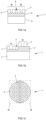
- the present description relates to a growth substrate 1 for the formation of optoelectronic devices.
- THE figures 1a and 1b schematically represent a section of two growth substrates. There figure 1c shows a top view of these substrates.
- Growth substrate 1 is intended to be placed in deposition equipment, such as an epitaxy frame, in order to form active layers of optoelectronic components on the exposed surface of substrate 1.
- This substrate 1 can also serve as a mechanical support allowing manipulation of the devices during the complementary manufacturing steps (formation of the electrical contacts, isolation of the devices from each other, etc.) leading to having a functional device.
- the growth substrate 1 comprises a growth support 2.
- This may be a circular wafer of materials, for example silicon or sapphire, of standardized size, for example 2 inches (50 mm), 4 inches ( 100 mm) or even 200 mm in diameter. But the growth substrate 1 is in no way limited to these dimensions or to this shape.
- the nature of the growth medium 2 is chosen to be able to withstand the treatments (such as deposits, heat treatments, etc.) implemented during the manufacture of the growth substrate 1 itself. and during production optoelectronic devices.
- the growth support 2 has a coefficient of thermal expansion similar or close to that of the materials which will form the useful layer of the optoelectronic device, in order to limit the significant stresses which could damage these devices at the end of their manufacture.
- the growth substrate 1 also comprises, arranged on the growth support 2, a plurality of crystalline semiconductor islands 3 (and designated more simply by the term “island(s)” in the remainder of this description).
- Each island 3 is intended to receive the active layers of an optoelectronic device, such as an LED, a laser or a photovoltaic cell.
- the islands 3 can be made of III-N materials.
- the islands 3 can consist of GaN or InGaN of wurtzite structure, whose axis c is perpendicular to the surface, and in which the proportion of indium can vary between 0% and 20%, and in particular between 1.5% and 8%.
- island is meant a block of material entirely separate from the other islands arranged on the growth support 2.
- crystalline is meant that the atoms constituting an island 3 are assembled in an orderly manner to form a block of monocrystalline material, this block may nevertheless include arrangement faults of the dislocation, slip plane or point fault type.
- the islands 3 are separated from each other via trenches 4. These trenches may have a lateral dimension, separating two islands 3, of between 0.1 and 50 microns, or 1 and 50 microns and typically of the order 2 microns or 20 microns. Each island has a relatively small size vis-à-vis the growth substrate, which can extend, in its largest dimension, for example between 1 micron to 1 mm, depending on the intended final application.
- the surface of the islands 3 can be between 1 ⁇ m 2 or 4 ⁇ m 2 and 1 mm 2 , and preferably between 25 ⁇ m 2 and 400 ⁇ m 2 .
- Each island 3 can have any shape, seen from above, for example circular, square, triangular, hexagonal or rectangular. Its thickness is typically less than 200 nm, in particular when it consists of InGaN.
- the islands 3 can all be of identical or different shapes and dimensions.
- the islands 3 do not all have the same mesh parameter.
- a first group of islands 3a has a first mesh parameter
- a second group of islands 3b has a second mesh parameter, different from the first.
- all the islands 3 are made of the same material.
- the materials of the islands 3 being identical to one another, the existence of a difference in lattice parameters denotes the existence of a different state of stress between the islands 3 constituting the two groups 3a, 3b.
- the materials of the islands 3 are not identical to each other from one group to another. Furthermore, the stress state of the islands 3 constituting the two groups 3a, 3b can also be different from one group to another. Consequently, the two groups of islands 3a, 3b have different lattice parameters.
- the variety of lattice parameters of the islands 3 of the growth substrate 1 will be used to collectively manufacture optoelectronic devices having distinct light properties, using a single manufacturing technology and on a single growth substrate.
- the first group of islands 3a which has the first lattice parameter
- a first LED emitting directly at a first wavelength for example in the green
- a second LED emitting directly at a second wavelength for example in the blue.
- directly emitting means that this emission corresponds to the light radiation emitted by the active layers (the quantum wells) of an LED, without requiring the use of conversion phosphorus.
- the growth substrate 1 can comprise at least a third group of islands, this third group having a third lattice parameter different from the first and from the second.
- the growth substrate can include any number of groups of islets, each group being formed of islets having a lattice parameter different from the islets belonging to the other groups. It will thus be possible to have a growth substrate 1 making it possible to form LEDs emitting in the field of red, green, blue and infrared wavelengths on the same substrate using a single technology.
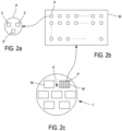
- the distribution and arrangement of the groups of islands 3a, 3b on the surface of the growth medium 2 is not a essential characteristic, and all possible distributions and arrangements are possible. They can sometimes be dictated by the intended application.
- first group of islands 3a occupies a first zone of the support 2 and the second group of islands 3b a second zone of the support 2, which are separate from each other and adjacent to each other.
- This arrangement is represented schematically in the figure 2a .
- Such a combination of LEDs constitutes a light pixel P whose emission color can be controlled.
- the islands 3, 3', 3" which will receive the constituent LEDs of these pixels P can be arranged in a regular manner on the surface of the growth support 2. It is thus possible to form monolithic pixels P, that is to say arranged on the same substrate and manipulated as a pixel, for example by a component insertion device, to be integrated into a functional device.
- the pixels P could for example be regularly distributed along rows and columns to form a matrix M, as shown in the figure 2b .
- a growth substrate 1 can comprise a plurality of such matrices M, as shown in the figure 2c .
- the growth substrate 1 also comprises at least one assembly layer 5 placed between the growth support 2 and the islands 3.
- the layer of assembly is directly in contact with the growth medium and with the islets 3, but the growth substrate could include other intermediate layers.
- This assembly layer 5 can comprise a dielectric such as a layer of silicon oxide or silicon nitride, or composed of a stack of such layers designed to, for example, facilitate subsequent removal of the growth support.
- the assembly layer 5 does not have a uniform thickness.
- the assembly layer has a first thickness in line with the islands 3 of the first group of islands 3a, and a second thickness, different of the first, to the right of the islets 3 of the second group of islets 3b. More generally, the assembly layer 5 has a distinct thickness in line with the islands of each of the groups of islands of the substrate 1.
- a strained crystalline semiconductor layer is first formed on a donor substrate. Then, this layer is transferred onto a substrate comprising a creep layer by bonding and by thinning and/or fracturing the donor substrate. Islands are then defined in the transferred layer, then the substrate and the islands are heat treated at a temperature above the viscous transition temperature of the creep layer, for example in BPSG, which leads to at least partial relaxation of the islets.
- the degree of relaxation obtained at the end of the thermal relaxation treatment can reach 70 to 80% or 95% of the maximum degree of relaxation corresponding to obtaining a perfectly relaxed layer. This degree of relaxation is dependent on the thickness of the islets, the duration and the amplitude of the heat treatment.
- the stiffener layer may be formed (or comprise) of a residue of the donor substrate which would have been preserved on the strained layer after its transfer to the creep layer. It may have been placed on the exposed face of the donor substrate to end up under the island at the end of the transfer of the strained layer and the formation of the islands.
- a relaxation substrate comprising a support 7, a creep layer 8 placed on the support 7 and, placed on the creep layer, a plurality of crystalline semiconductor islands 9 having a parameter of initial cell, at least part of this plurality of islands being constrained islands.
- a first group of islets 9a has a first lateral expansion potential and a second group of islets 9b has a second lateral expansion potential, different from the first.
- lateral expansion potential is meant the lateral expansion or contraction that an island 9 must undergo to reduce its elastic stress energy and balance it with the restraint energy of the creep layer 8 with which he is in touch.
- the methods also provide for thermal treatment of the relaxation substrate 6 at a relaxation temperature greater than or equal to the glass transition temperature of the creep layer 8 to cause the differentiated relaxation of the islands of the first and of the second group, the lattice parameter relaxed islands of the first group 3a and relaxed islets of the second group 3b then exhibiting different values
- a first manufacturing method comprises providing a relaxation substrate comprising a relaxation support 7, a creep layer 8 disposed on the support 7 and disposed on the creep layer 8, a plurality of semiconductor crystal islands constrained islands 9.
- the constrained islands 9 all have the same mesh parameter. Reference may be made to the cited documents of the state of the art to choose the nature of the relaxation support 7 and of the creep layer 8.
- the donor substrate may consist of a sapphire base support, a buffer layer of GaN formed on the base substrate and a strained layer of InGaN with an indium proportion between 1% or 1, 5% and 10% or 20% on the GaN buffer layer.
- Conventional steps of photolithography, resin deposition and etching may have been used to define, from the continuous layer of InGaN, the strained islands 9 of InGaN. These steps may have been applied before or after the transfer steps.
- the islands 3 can support a stiffening layer 10', residue of the donor substrate. It can thus act with a thickness comprised between 10 and 100 nm of GaN which initially formed the buffer layer of the donor substrate.
- the strained islands 9 of the relaxation substrate are selectively treated in a following stage of the manufacturing process so as to form a first group of strained islands 9a having a first potential for lateral expansion and a second group of constrained islands 9b presenting a second potential for lateral expansion, different from the first.
- the stress energy contained in an island of the first group 9a is different from the stress energy contained in an island of the second group 9b.
- Such a selective treatment may comprise the formation of a stiffening layer 10 having a first thickness on a first group of constrained islands 9a of the relaxation substrate 6 and a second thickness, different from the first, on a second group of islands 9b . This arrangement is shown on the figure 3c .
- This configuration of thickness of the stiffening layer 10 can be obtained by forming an initial stiffening layer of uniform thickness 10 'on all the islands 9, as shown in the figure 3b , then by selectively thinning this layer 10' to reduce its thickness on one of the two groups of islands 9a, 9b. It is again possible to use photolithographic masking steps to protect the stiffening layer 10 placed on one of the groups of islands from this thinning treatment. Alternatively to a thinning, it is also possible to choose to thicken the initial stiffening layer 10' on one of the two groups of islands 9a, 9b to achieve the configuration of the figure 3c . As we have seen, this stiffening layer 10' of uniform thickness can consist of a residue of the donor substrate.
- stiffening layer 10 can have a uniform thickness from one group of constrained islands 9a, 9b to the other.
- the stiffening layer 10 is typically made of a silicon oxide or a silicon nitride. But it can be any other material that is sufficiently rigid to modify the potential for lateral expansion of the island 9 on which it rests and, potentially, to avoid the warping of this island 9 during the thermal relaxation treatment that will follow. Depending on the nature of this layer, and the expected degree of relaxation of the island 9 on which it is placed, the stiffening layer 10 may have a thickness of between 10 nm and several hundred nm, such as 200 nm.
- the selective treatment aimed at differentially affecting the lateral expansion capacity of the islets 9 can also comprise the thinning of some of the islets 9, that is to say to reduce the thickness of the islets 9a of the first group of islets and/or the thickness of the islets 9b of the second group of islands so that these islands 9a, 9b, at the end of this treatment have different thicknesses. It may for example involve thinning at least one group of islets 9a, 9b from 10% to 50% of its initial thickness, in order to create a difference in thickness between these groups of islets which may be greater than 10 %.
- This variant is particularly useful when the stiffening layer has been formed between the flow layer 8 and the crystalline semiconductor island 9a, 9b, for example by placing a layer of stiffening material on the donor substrate, before the transfer of the layer stress on the relaxation support.
- the stiffening layer is formed under only some of the constrained islands 9.
- the stiffening layer can be formed beforehand, formed on the exposed surface of the donor substrate 11 and locally etched so as to selectively form islands with or without this layer. underlying, or with a variable thickness of this stiffener layer.
- the islands 9 having an underlying stiffening layer will have a lower lateral expansion potential than the islands without a stiffening layer, for an identical creep layer.
- the relaxation substrate 6 is heat treated at a temperature greater than or equal to the glass transition temperature of the creep layer 8.
- this heat treatment may comprise the exposure of the relaxation substrate to a temperature between 400°C and 900°C for a period of a few minutes to several hours. This is particularly the case when the creep layer is made of BPSG.
- the relaxation of the constrained islets 9 of the first and of the second group of islets 9a, 9b is caused to form at least partially relaxed islets 3, represented on the figure 3e .
- the degree of relaxation obtained during and at the end of the thermal relaxation treatment depends on the thickness of the island 9, the thickness and/or the nature of the stiffening layer 10 possibly covering this island 9.
- the constrained islets of the first group 9a and the constrained islets of the second group 9b having different characteristics and therefore a different lateral expansion potential, the heat treatment results in the initially constrained islets 9 of the first and second groups being relaxed to different degrees. 9a, 9b.
- the lattice parameter of the islets 3 of the first group 3a is different from the lattice parameter of the islets 3 of the second group 3b.
- a relaxation substrate 6 comprising a relaxation support 7, a creep layer 8 placed on the support 7 and, placed on the creep layer 8, a plurality of strained semiconductor crystalline islands 9.
- the strained islands 9 all initially have the same mesh parameter.
- the creep layer 8 is composed of a first group of blocks 8a and a second group of blocks 8b.
- each group 8a, 8b is made up of a single block for reasons of simplification of the description, but in general, a group of blocks can be made up of one or a plurality of blocks.
- the term “block” should be understood in a very broad sense, designating any block or combination of blocks of homogeneous material, this block defining any volume, which is not necessarily convex.
- the blocks of the first group 8a and the blocks of the second group 8b consist of different materials, which for a determined temperature, respectively have a first and a second viscosity which are different from each other.
- the constrained islands 9 arranged on the blocks 8a of the first group form a first group of constrained islands 9a and, similarly, the constrained islands 9 arranged on the blocks 8b of the second group form a second group of constrained islands 9b.
- the constrained islands 9 are likely to relax, at least partially, in a differentiated manner.
- the constrained islets of the first group 9a have a different relaxation potential from the relaxation potential of the constrained islets 9b of the second group.
- the strained islands 9 are all of the same size, the stress energy that they contain are also quite similar, but the nature of the blocks on which they rest being different, the islands 9 are likely to relax in a differentiated manner .
- the strained islands 9 may come from a donor substrate 11, and have been transferred to the flow layer 8 of the relaxation substrate 6 by steps identical or similar to those presented in relation to the description of the first method.
- THE figures 5a to 5d represent a sequence of possible steps to produce a creep layer 8 composed of blocks 8a, 8b of different viscosities.
- a first creep layer 8a is formed on the support 7. It may be a dielectric layer of silicon dioxide, or silicon nitride, comprising a determined proportion of boron and/or phosphorus to give it a first viscosity value.
- at least one recess 10 is provided by partial masking and etching of the first creep layer 8a.
- the recess 10 can be partial, as shown in the figure, or correspond to the entire thickness of the first creep layer 8a.
- the remaining first layer 8a and the recess 10 are covered with a second creep layer 8b.
- This second layer 8b preferably, has a sufficient thickness to completely fill the recess 10.
- the material constituting the second creep layer 8b is of a different nature from the first layer 8a so that the first and the second layer have a different viscosity. when exposed to a specified relaxation temperature.
- This different viscosity can be either higher or lower than that of the first layer 8a.
- the first layer is made of silicon dioxide or silicon nitride, which has particularly high viscosities, it will be possible to choose the material of the second layer 8b in BPSG, with a sufficient proportion by mass of boron and phosphorus, by example greater than 4%, to have a lower viscosity than that of the first layer.
- the exposed surface of the substrate is then planarized to eliminate the second creep layer outside the recesses 10 until the first creep layer 8a is exposed. In this way, the first blocks 8a and the second blocks 8b constituting the creep layer 8 are formed. .
- the relaxation substrate 6 is heat treated at a relaxation temperature greater than or equal to the glass transition temperature of the creep layer, that is to say of at least one of the first and second blocks 8a, 8b of the creep layer 8 to cause the differentiated relaxation of the islands 9a, 9b of the first and the second group.
- the heat treatment may comprise the exposure of the relaxation substrate 6 to a relaxation temperature of between 400° C. and 900° C. for a period of a few minutes to several hours. This causes the lateral expansion of the constrained islands 9 of the first and the second group of islets 9a, 9b to form at least partially relaxed islets 3, represented on the figure 4c .
- the constrained islets of the first group 9a and the constrained islets of the second group 9b resting on blocks having a different viscosity at the relaxation heat treatment temperature, and therefore having a different lateral expansion potential
- the heat treatment results in the initially constrained islands 9 of the first and second groups 9a, 9b being relaxed to different degrees, and in causing their differentiated lateral expansion. Consequently, at the end of the thermal relaxation treatment, the lattice parameter of the islets 3 of the first group 3a is different from the lattice parameter of the islets 3 of the second group 3b.
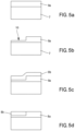
- This third method comprises the preparation of a donor substrate 11 comprising a plurality of strained elementary layers of crystalline semiconductors 12a, 12b forming a stack 12.
- the stack has at least a first zone 13a and a second zone 13b having levels different constraints.
- the first step of preparing the donor substrate 11 has been shown. It comprises supplying a base substrate 14, for example consisting of sapphire, silicon or silicon carbide.
- a stack 12 of elementary semiconductor and crystalline layers is formed on the base substrate 14, each layer of the stack having a different nature.
- two elementary crystalline semiconductor layers 12a, 12b have been formed.
- the first elementary layer 12a may be a layer of gallium nitride having a thickness of 2 microns or more, forming a buffer layer and whose upper part is essentially relaxed.
- the second elementary layer 12b may be a layer of InGaN with a thickness of around 100 nm and the proportion of indium of which is around 6%.
- the second elementary layer 12b of the stack 12, and in general each elementary layer of the stack 12, has a thickness less than its critical relaxation thickness. At least some of the layers are therefore stressed, in compression in the example taken above. In this way, the second elementary layer 12b (or each layer of the stack 12 formed on the first elementary layer 12a) is pseudomorphic and therefore has a lattice parameter identical to that of the first layer 12a of the stack 12.
- FIG. 6b a following step in the preparation of the donor substrate 11, consisting in locally eliminating the second elementary layer 12b to expose part of the first elementary layer 12a.
- This elimination step can implement traditional means of photolithographic masking and etching, for example dry etching.
- a first zone 13a in which the first layer 12a is exposed, and a second zone 13b where the second layer 12b of the stack is exposed, are defined in this way, on the exposed surface of the donor substrate 11.
- part of the stack 12 is locally eliminated so as to preserve, in respective zones 13, only part of the layers forming the stack 12.
- the zones 13 have different stress levels. one from the others, since each zone 13 is respectively formed from a different stack of one or a plurality of elementary layers, each in a different state of stress.
- zone 13a consists of first layer 12a and has a first reference stress level.
- Zone 13b consists of the stack formed of the first elementary layer 12a and the second elementary layer 12b strained. The second zone 13b therefore has a stress level higher than that of the first zone 13a.
- Zones 13a, 13b are not necessarily all in one piece, that is to say the local elimination of the elementary layers of the stack 12 to expose a particular layer can be carried out at a plurality of locations. distinct and not joined.
- the term "zone” will denote the collection of locations on the surface of the donor substrate 11 exhibiting the same stress level, for example for which the same layer 12a, 12b of the stack 12 is exposed at the end of this elimination step.
- the first and the second zone 13a, 13b of the donor substrate will each make it possible respectively to form the islets 3 of the first and of the second group of relaxed islets 3a, 3b of a growth substrate 1. It will therefore be sought to define these zones at the surface of the donor substrate 11 so that they correspond to the chosen arrangement of the islets 3 of the groups of islets 3a, 3b, as has been explained previously in relation to the figures 2a to 2c .
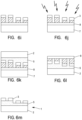
- the following stages of preparation of the donor substrate 11, represented on the figures 6c and 6d aim to prepare the transfer of the stack 12 thus defined on a relaxation support 7.
- an adhesive layer 15 having a flat and smooth exposed surface. It may be a layer of dielectric, for example silicon dioxide or silicon nitride. When it comes to silicon dioxide, the latter may include boron and/or phosphorus to give it creep properties when the bonding layer 15 is exposed to a temperature above its glass transition temperature.
- This bonding layer 15 is deposited with a sufficient thickness to make it possible to completely encapsulate the stack 12 and thus provide a flat surface. When its formation provides for the application of a polishing step, the removal of thickness which occurs during this treatment will be taken into account. By way of example, a thickness of 500 nm or more of the material can be deposited to form the bonding layer 15.
- light species such as hydrogen or helium
- the introduction of these species results in the formation of a fragile plane 16 making it possible to eliminate, in a later stage of the manufacturing process, the base substrate 14 and allowing the transfer of the stack 12 to the relaxation support 7.
- the plane fragile 16 can preferably be located in the base support 14 or in the first elementary layer 12a of the stack 12, so that the stack 12 is actually transferred onto the support 7.
- this third manufacturing method is in no way limited to a transfer implementing the formation of a weakening plane 16. It is possible to envisage carrying out the transfer on the support 7 by mechanical-chemical removal of the base support 14 especially when it is made of silicon. We can also consider its detachment by laser irradiation of the interface separating the base substrate 14 and the first elementary layer 12a, in particular when this base substrate is made of sapphire.
- the relaxation support 7 has been provided beforehand with a creep layer 8 so that after the operation of removing the base support 14, there is a relaxation substrate 6 comprising the relaxation support 7, the layer creep 8, bonding layer 15, and stack 12 of elementary layers of strained crystalline semiconductors defining areas 13 having different stress levels.
- trenches 4 are made in the stack 12 so as to define constrained islands 9.
- the trenches 14 are made in the stack 12 to define the islands 9 of a first group 9a in the first zone 13a, and the islands 9 of a second group of islands 9b in the second zone 13b.
- These trenches 4 can penetrate into the bonding layer 15 or even into the flow layer 8.
- This step of defining the islands 9 can be carried out after the transfer of at least part of the stack 12 as has been presented here , but it is also possible to envisage carrying out this step prior to the transfer of the stack 12, directly on the donor substrate 11. As we have seen, the formation of the trenches 4 can lead to defining islands 9 of shapes and dimensions very varied.
- a relaxation substrate 6 comprising a support 7, a creep layer 8 placed on the support and an adhesive layer 15 placed on the creep layer 8 is available.
- the creep layer 8 and the bonding layer 15 can both be made of BPSG and therefore have creep properties.
- the relaxation substrate 6 also comprises, on the creep layer 8, a plurality of crystalline semiconductor islands all having the same initial lattice parameter.
- a first group of islands 9a has a first level of constraints. These are the islands 9 which have been formed in the stack 12 at the level of the first zone 13a of this stack.
- a second group of islands 9b has a second level of constraint, different from the first. These islands 9 of the second group 9b are those which have been formed in the stack 12 at the level of the second zone 13b of this stack.
- the relaxation substrate 6 can comprise a plurality of groups of islands having between them different stress levels, each group of islands having been formed, in the stack 12, at the level of a zone 13 distinct from this stack 12.
- the constrained islands 9 of each group of islands have a different lateral expansion potential from one group to another.
- the stress energy contained in an island 9 of the first group 9a is different from the stress energy contained in an island 9 of the second group 9b.
- the relaxation substrate 6 may for example be a heat treatment bringing the substrate 6 to 800° C. for four hours. More generally, the relaxation temperature of this heat treatment will be chosen so that it exceeds the glass transition temperature of the creep layer 8, and possibly that of the bonding layer 15 when the latter has properties of creep. This relaxation temperature is typically between 400°C and 900°C. The heat treatment can last between 30 minutes and several hours.
- the islets forming the different groups of islets 9a, 9b initially exhibiting different stress levels the application of the thermal relaxation treatment leads to the relaxation and to the differentiated lateral expansion of the islets of a group to another.
- the relaxed islets 3 of the first group 3a and the islets 3 of the second group 3b then have different lattice parameters.
- the islets 3 can for example be transferred to a growth support 2 via an assembly layer 5.
- the islets 3 are covered with the assembly layer 5, this layer is assembled, which may have undergone treatments to facilitate this, to Growth Support 2 ( figure 6k ) and eliminates the relaxation support 7 by any appropriate means to obtain the structure of FIG. 3l.
- the flow layer 8 and the bonding layer 15 are then removed from the structure obtained. Additional etching steps can make it possible to remove the excess assembly layer 5, thus making it possible to have a growth substrate 1 ( figure 6m ) as previously described in relation to the figure 1b .
- the degree of relaxation obtained during and at the end of the thermal relaxation treatment depends, among other things, on the size of an island 9, its level of stress, and the nature of the creep layer 8 on which it rests, and more particularly the viscosity of the material which makes up this layer (or this block in the case of the second method).
- This transfer may include transferring the islets to an intermediate support, before transferring them to this other support.
- This provides a growth substrate that does not include a creep layer, which may be incompatible with the steps for manufacturing the active layers of optoelectronic devices.
- this transfer makes it possible, in the case where the islands consist of a polar material, to recover on the exposed face of the growth medium 1 the initial polarity of this material, as it had been formed on the donor substrate.
- a method for the collective manufacture of a plurality of optoelectronic devices is described.
- the invention relates to this method of using the growth substrate.
- These devices each comprise active layers which may be different from one device to another.
- the devices then have different optoelectronic properties from each other.
- collective fabrication it is meant that the fabrication of these devices employs a single technology applied to a single substrate to form the active layers.
- This method comprises the supply of a growth substrate 1, in accordance with the general description which has just been given. It therefore comprises at least a first group of crystalline semiconductor islands 3a having a first lattice parameter and a second group of crystalline semiconductor islands 3b having a second lattice parameter, different from the first.
- the next step aims to form the active layers by growth on the exposed face of these islands 3.
- the growth substrate is placed for this in a deposition chamber, for example that of a frame of epitaxy.
- a deposition chamber for example that of a frame of epitaxy.
- gases comprising the atomic elements constituting the active layers which it is desired to deposit on the islands 3.
- the precursor gases are brought to temperature above the substrate of growth 1 so as to release the atomic elements, and allow their adsorption on the surface of the growth substrate 1 and in particular on the surface of the islands 3.
- the relative concentration and the duration of circulation of these precursor gases it is possible control the nature and the thickness of the layers which are gradually formed on the crystalline semiconductor islands 3.
- dopants of p or n type
- the precursor gases may form, on the islands, active layers of electronic devices, such as quantum wells or heterostructures of LEDs.
- the precursor gases to form these active layers of LEDs can include trimethylegalium (TMGa), triethylgallium (TEGa), trimethylindium (TMIn) and ammonia (NH3).
- the incorporation of certain atomic elements of the precursor gases into the deposited layer is affected by the lattice parameter of this layer. This is particularly the case with regard to the incorporation of indium in an InGaN layer as reported in the document " Strain effects on indium incorporation and optical transitions in green-light InGaN heterostructures of different orientations. by MV Durnev et al, Phys. Status Solidi A 208, No. 11, 2671-2675 (2011 ). It appears that the solubility of indium in a material increases when the lattice parameter of this material increases. In other words, and all other things being equal, the incorporation of indium into a material during its formation by deposition increases with the lattice parameter of the material in which it is incorporated.
- the method implements a step of exposing the growth substrate 1 to an atmosphere comprising at least an initial concentration of an atomic element.
- the atomic element On the islands 3 of the first group 3a of the growth substrate 1, which has a first lattice parameter, the atomic element is incorporated into the active layer in a first concentration. On the islands 3 of the second group of islands 3b, which has a second lattice parameter different from the first, the atomic element is incorporated into the active layer according to a second concentration, different from the first. If the second lattice parameter is greater than the first, the second concentration will be greater than the first.
- the first and the second concentration are determined by the initial concentration of the atomic species in the chamber and by the first and the second lattice parameter of the islands.
- other parameters can also influence the nature of the layers that form, such as the pressure of the chamber, the temperature, the respective flow rate of the precursors, etc.
- the proportion of indium incorporated into the active layers of InGaN deposited on the islands of the first group of islands can lead to the formation of LEDs directly emitting radiation in the blue range.
- the proportion of indium incorporated into the active layers of InGaN deposited on the islands of the second group of islands can lead to the formation of LEDs directly emitting radiation in the green range.
- the process for manufacturing the electronic devices can be continued, in particular to form the electrical contacts and isolate the devices from each other, as described for example in the document US9478707 . It is also possible to transfer islands 3 provided with their active layers onto a support of LEDs, and to eliminate the growth support 2.
- a particular application of the growth substrate and of the collective manufacturing process which have just been described aims to manufacture a monolithic micro panel of LEDs.
- a micro panel consists of an arrangement of LEDs, generally all identical and of very small size, arranged at constant pitch in rows and columns on a panel support.
- the micro panel is said to be “monolithic”. This characteristic is advantageous, because the LEDs then have very similar properties (such as current and/or voltage behavior, evolution with aging, etc.), which facilitates the design and manufacture of the micro panel.
- a monolithic LED micro-panel will denote a micro-panel in which all the LEDs have been collectively manufactured and collectively extracted from the same manufacturing support to form the micro-panel; or a micro panel composed of monolithic pixels, i.e. each pixel is made up of collectively manufactured LEDs extracted from the same manufacturing support. In this case, the monolithic pixels are assembled together to form the micro panel.
- the monolithic micro-panel of LEDs can be assembled with a control circuit by direct chip transfer technology (often referred to by the Anglo-Saxon name "Flip Chip”) making it possible to electrically connect each LED of the micro-panel with a drive circuit of the driver circuit.
- This assembly may consist in assembling an entire monolithic micro panel to a driver circuit, each LED of the micro panel being after assembly associated with a driver circuit. Or the assembly may consist of successively assembling one or a plurality of monolithic pixels to the driver circuit to associate them with the driver circuit. Whichever approach is chosen, a monolithic display microscreen is thus formed.
- the drive circuits of the driver circuit can also have the same or similar electrical properties, which greatly facilitates the manufacture of the display microscreen.
- the known monolithic micropanels are all made up of LEDs directly emitting a single wavelength, thus allowing a monochrome display.
- the color display is obtained by means of conversion phosphor placed on the emission face of some of these LEDs, or by optically combining a plurality of micro panels each emitting radiation chosen in a combination of complementary colors, for example red, green and blue.
- the methods and substrates in accordance with the present description make it possible, on the contrary, to propose a monolithic micro panel of LEDs comprising a panel support and a plurality of LEDs arranged on this panel.
- the plurality of LEDs comprises a first group of LEDs capable of directly emitting light radiation exhibiting a first wavelength, and a second group of LEDs capable of directly emitting a second light radiation exhibiting a second wavelength different from the first one.
- a micro panel is therefore capable of emitting different colors without requiring optically combining a plurality of micro panels or applying conversion means.
- the micro panel comprises at least three groups of LEDs, each group emitting at a different wavelength from the others. It is for example possible to have a first group of LEDs emitting directly in the red, a second group of LEDs emitting radiation directly in the green and a third group of LEDs emitting radiation directly in the blue. It is also possible to envisage having a fourth group of LEDs emitting directly in the infrared, this illumination being able to be used to provide additional functionalities to the device integrating the micro panel (touch function, recognition of the iris of the eye, motion detection, etc.).
- the LEDs of each group are arranged regularly on the panel support, for example spaced apart at a constant pitch along rows and columns, in order to form a display matrix. They are also arranged to place side by side, or more precisely close to each other, an LED of each group, so as to form at each location of the matrix a light pixel whose color can be controlled.
- the size of the LEDs can vary according to the group in order to play on the distribution of the luminous intensities of the different colors of emission. For example, the red LEDs may be larger than the blue and green LEDs.
- the micro panel can be made up of LEDs making it possible to form a matrix of pixels of large dimensions, for example 50 pixels by 50 pixels, or 200 pixels by 200 pixels, or even more.
- the luminous pixels of the panel consist of LEDs emitting in different wavelengths
- these LEDs have been collectively formed from a single technology and on a single substrate. They therefore have properties, and in particular electrical and aging properties, which are very similar to each other, which makes it possible to associate them with a control circuit consisting of driver circuits which are all identical or very similar.
- a growth substrate 1 comprising on a growth support 2 provided with an assembly layer of silicon oxide 3 is first prepared.
- the growth support may for example consist of a wafer of 150 mm diameter sapphire.
- the growth substrate comprises three groups of islands 3a, 3b, 3c of InGaN comprising 8% indium.
- the islands 3a, 3b, 3c all have a thickness of 200 nm and a square shape with sides of 50 microns.
- the first group of islands 3a has a lattice parameter of 0.3190 nm
- the second group has a lattice parameter of 0.3200 nm
- the third group has a lattice parameter of 0.3205 nm.
- the islets 3 constituting each of these groups are distributed and arranged on the growth support 2 according to a matrix arrangement in accordance with what has been explained in relation to the description of the figures 2a to 2c .
- Three islands 3, 3', and 3" of each of the groups are therefore arranged close to each other so as to define a pixel; and these groupings of islands distributed in a matrix along rows and columns on the surface of the substrate growth 1. It is possible to provide panel trenches 4′ wider than the trenches 4 separating two islands to separate the matrices from each other, each matrix delimiting a set of islands 3, 3′, 3′′ intended to receive the LEDs of a micro panel.
- a relaxation substrate 6 is first prepared comprising a relaxation support 7, for example in sapphire also 150 mm, and a flow layer composed of BPSG.
- the relaxation substrate also comprises strained islands 9 of InGaN comprising 8% indium. These constrained islands 9 are arranged similarly to what has just been described for the relaxed islands 3 of the growth substrate 1.
- the parameter of the same for the constrained islands 9 is 0.3185 nanometer.
- the strained islands 9 are covered with an initial stiffening layer 10' of GaN 50 nm thick, the residue of a buffer layer of GaN from a donor substrate having been used to produce the relaxation substrate.
- a thermal relaxation treatment is carried out, for example at 800° C. for one hour. This treatment leads to the relaxation of the initially constrained islets 9, to form partially relaxed islets 3 which, at the end of the thermal relaxation treatment, have a lattice parameter close to 0.3190 nanometer. If this is not the case, the application of the thermal relaxation treatment can be repeated, possibly by thinning the initial stiffening layer to promote the relaxation of the islets 3.
- the stiffener layer 10' which covers the islands 3 of the second and third groups is then eliminated by etching, and the relaxation heat treatment is repeated. Provision can also be made to thin the islands 3 of the second and third group, for example by 40 nm, to promote their relaxation.
- the lattice parameter of the islands of the first group, covered by the layer of stiffener 10 has varied relatively little, close to 0.3190 nm.
- the lattice parameter of the islands of the second and the third group has grown to be close to 0.3200 nm.
- the islets of the third group are thinned, for example by 70 nm, and the thermal relaxation treatment is again applied.
- the lattice parameters of the islands of the first and second group remain relatively constant, and are in any case less affected by this heat treatment than the lattice parameter of the islands of the third group which is then close to 0.3205 nm.
- This final relaxation heat treatment can be repeated, possibly in combination with a thinning of the stiffener layer placed on the islands of the first group or a thinning of the islands of the second and second group, to make the mesh parameters of these islands converge towards their target mesh parameters.
- the repetition of these steps leads to the selective relaxation of the groups of islets and, at the end of these steps, the first group of islets 3a has a lattice parameter of, or close to 0, 3190 nanometer, the second group has a lattice parameter of or close to 3.200 nanometers and the third group has a lattice parameter of or close to 3.205 nm.
- the partially relaxed islands 3 of InGaN are then transferred by bonding to a growth support 2 provided with an assembly layer 5, for example a multilayer of silicon dioxide and nitride.
- TMGa precursor gas
- TEGa precursor gas
- TMIn precursor gases
- the lattice parameters of the islands of the first group, the second group and the third group of islands are different from each other, the incorporation of indium into the active layers of InGaN which form on the islands of these groups is also different.
- LEDs are obtained which directly emit radiation in the blue domain, on the islands of the second group LEDs which directly emit radiation in the green domain, and on the islands of the third group LEDs are formed. directly emitting radiation in the red range.
- an active layer of LEDs arranged at the level of a pixel and emitting colors in the red, green and blue range.
- the wafer on which the LEDs which have just been formed rest can be cut according to the trenches 4' defining the pixel matrices. Each of these matrices then constituting a micro panel.
- the wafer comprising the micro-panels to a second wafer on which pilot circuits consisting of a matrix of drive circuits have been formed.
- Each matrix is arranged on the surface of this wafer according to the same arrangement as the LEDs on the growth substrate.
- the assembly makes it possible to put each diode in electrical contact with a driver circuit.
- a plurality of display screens are formed in a single contacting step. It is then possible to choose to eliminate the growth medium 2, for example by laser irradiation, and the assembly layer 5, for example by chemical etching, so as to expose a light-emitting surface of the LEDs. These surfaces can be prepared with optical elements, coatings or surface protection to improve the quality and robustness of the screen.
- the wafer can be cut in a conventional manner so as to isolate the screens from each other for the purpose of packaging them.
- the second and third layer it is possible to provide an intermediate layer of AlGaN comprising between 0% and 10% aluminum and with a thickness of between 1 and 3 nm.
- This intermediate layer makes it possible to ensure that the stack 12, in particular the third elementary layer, is indeed pseudomorphic, that is to say that all the elementary layers all have the same lattice parameter. As the concentration of indium from one layer to another increases, the stress level of each layer also increases.
- the first, second and third elementary layers are exposed at three zones of the donor substrate. Each zone is respectively distributed on the surface of the donor substrate 11 according to the pixel and matrix distribution presented in relation to the figures 2a to 2c .
- a bonding layer 15 500 nm thick is prepared, comprising silicon dioxide and boron and phosphorus in a mass proportion of 4%.
- the bonding layer is polished to allow its assembly to a sapphire growth support 7.
- the stack 12 of the elementary layers is then transferred to a sapphire relaxation support 7, also 150 mm in diameter, for example according to the invoice implantation technique detailed in the general description of the process.
- the sapphire substrate 7 has previously been provided with a creep layer 8 of BPSG, that is to say comprising silicon dioxide and boron and phosphorus, here in a mass proportion of 4% phosphorus and 6 % boron.
- the islands 9a of the primer group of islands are defined in the first zone 13a
- the islands 9b of the second group are defined in the second zone
- the islands of the third group are defined in a third zone of the stack.
- the islands 9a, 9b are here all square and have a side of 10 microns.
- the islands 9 of the first group consist of a single layer of GaN, the first elementary layer which is essentially relaxed.
- the islands 9 of the second group consist of a stack formed of a GaN layer and an InGaN layer comprising 6% indium, the second strained elementary layer.
- the islands of the third group consist of a stack formed of a GaN layer, an InGaN layer comprising 8% indium (the second elementary layer) and an InGaN layer comprising 16% indium. indium (the third elementary layer).
- a first thermal relaxation treatment is carried out aimed at causing the creep layer 8 and the bonding layer 15 to flow and to release the stresses of the islands.
- the step is carried out at 800° C. for 4 hours.
- the islands 9 of the first group of islands are not constrained, their lattice parameter therefore does not change during this heat treatment.
- the islands of the second and the third group are composed of a stack of layers having different stress levels.
- the lattice parameter of these islands tends towards the equilibrium lattice parameter of the stack of layers which constitutes them.
- the parameter obtained will be close to the lattice parameter of the (In,Ga)N alloy of average composition over the thickness of the stack.
- the islets are partially etched to thin them.
- the etched thickness is typically around 100 nm.
- the thickness of the islands is then approximately 50 to 60 nm.
- the creep of the creep layer 8 and of the bonding layer 15 is again caused by applying a new thermal relaxation treatment to release the residual stresses of the islands of the second and third group.
- the conditions of the second heat treatment are identical to the conditions of the first.
- the thermal relaxation treatment can be renewed, optionally in combination with a thinning of the islets, to make their lattice parameters converge towards their target lattice parameters.
- the repetition of these steps leads to the differentiated relaxation of the groups of islets and, at the end of these steps, the first group of islets 3a has a lattice parameter typically between 3.180 A and 3.190 A, the second group has a lattice parameter between 3.210 A and 3.225 A, and the third group has a lattice parameter between 3.240 A and 3.255 A.
- the relaxed or partially relaxed islets 3 are then transferred by bonding to a growth support 2 provided with an assembly layer 5, for example a multilayer of silicon dioxide and nitride.
- a growth substrate 1 is thus formed. This process can be continued similarly to that of example 1, by growing active layers of nitride-based LEDs on each of the islands and by completing the manufacture of functional LEDs on the growth substrate, in particular by forming the LED contacts on either side of the active layers, or in the form of a monolithic panel.
- a growth substrate 1 is prepared comprising, on a growth support 2 provided with an assembly layer 5 composed of a stack of 500 nm of carbon oxide. silicon in contact with the sapphire support, 200nm of silicon nitride, and one micron of silicon dioxide.
- This stack is designed to allow the detachment by laser irradiation of the growth medium in a subsequent step of the process.
- This growth medium may for example consist of a sapphire wafer 150 mm in diameter.
- the growth substrate has three groups of islands of InGaN comprising 18% indium. The islands all have a thickness of 40 nm and a square shape with sides of 10 microns.
- the first group of islands has a lattice parameter of 0.3184 nm
- the second group has a lattice parameter of 0.3218 nm
- the third group has a lattice parameter of 0.3248 nm.
- the islets 3 constituting each of these groups are distributed and arranged on the growth support 2 according to a matrix arrangement in accordance with what has been explained in relation to the description of the figures 2a to 2c and the two previous examples.
- a relaxation substrate 6 is first prepared comprising a relaxation support 7, for example in sapphire also of 150 mm, to form a flow layer 8 thereon.
- the preparation of the flow layer firstly comprises the formation of a disassembly layer composed of a stack of 500 nm of silicon oxide in contact with the sapphire support and of 200 nm of silicon nitride.
- This disassembly stack is designed to allow detachment by laser irradiation of the relaxation support 7 in a later stage of the process.
- a first layer of one micron of silicon dioxide is formed on the dismantling layer.
- recesses are formed in the first layer arranged on the surface of the support to be in correspondence with the islands of the second group and reducing the thickness of the first layer of silicon dioxide to 100 nm.
- a second layer about one micron thick, this second layer consisting of silicon dioxide and a mass proportion of 3% of boron and 4% Phosphorus.
- Masking steps by photolithography and etching are repeated to form new recesses, this time arranged on the surface of the substrate to be matched with the islands of the third group.
- the etching is carried out to remove the entire thickness of the second layer of BPSG and preserve a thickness of 100 nm of the first layer of silicon dioxide.
- a third layer consisting of silicon dioxide and a mass proportion of 4% boron and 4% phosphorus is then deposited.
- the surface is planarized to partly eliminate the third and second layers so as to form the first, second and third group of blocks constituting the creep layer 8.
- the relaxation substrate also comprises strained islands 9 of square InGaN with sides of 10 microns comprising 18% indium transferred onto the creep layer 8 according to a layer transfer method detailed in the general description, and by producing sliced 4. These constrained islands 9 are arranged similarly to what has just been described for the relaxed islands 3 of the growth substrate 1.
- the lattice parameter of the constrained islands 9 is 0.3184 nanometer. Each constrained island 9 rests on a tile of one of the first, second and third groups, thus defining a first, a second and a third constrained island group.
- the strained islands 9 are covered with an initial stiffening layer of GaN 50 nm thick, residue of a buffer layer of GaN from a donor substrate having been used to produce the relaxation substrate.
- a thermal relaxation treatment is carried out, for example at 750° C. for one hour. This treatment leads to the lateral expansion of the initially constrained islands 9, to form partially relaxed islands 3.
- the viscosity of the blocks of the third group is estimated at 1E10 Nm -2 .s -1 approximately, that of the blocks of the second group is estimated at approximately 4E10 Nm -2 .s -1 , and that of the blocks of the first group, made of silicon dioxide, is not viscous, that is to say it has a viscosity greater than 1E12 Nm -2 .s -1 .
- the stress relaxation rate in the islets of the third group is 90%, so they have a lattice parameter of 3.246 ⁇ .
- the stress relaxation rate in the islets of the second group is about 50%, giving a lattice parameter of 3.218 ⁇ .
- the lattice parameter of the islets of the first group has not changed and remains at 3.184 ⁇ .
- the estimated viscosity values are given by way of example only.
- the heat treatment time can be adjusted so that the relaxation rate of the island placed on the block of intermediate viscosity is at the end of the process between 40 and 60%, and the relaxation rate of an island laid out on a pavement of lower viscosity is higher than 70%.
- the lattice parameters of the islands of the first, second and third group are respectively 3.184 ⁇ , 3.218 ⁇ and 3.248 ⁇ approximately, ie to within 0.005 ⁇ .
- the partially relaxed islands 3 of InGaN are then transferred by bonding to a growth support 2 provided with an assembly layer 5, for example a multilayer of silicon dioxide and nitride.
- assembly layer 5 for example a multilayer of silicon dioxide and nitride.
Landscapes
- Engineering & Computer Science (AREA)
- Power Engineering (AREA)
- Microelectronics & Electronic Packaging (AREA)
- Computer Hardware Design (AREA)
- Manufacturing & Machinery (AREA)
- Physics & Mathematics (AREA)
- Condensed Matter Physics & Semiconductors (AREA)
- General Physics & Mathematics (AREA)
- Recrystallisation Techniques (AREA)
- Led Devices (AREA)
- Crystals, And After-Treatments Of Crystals (AREA)
Applications Claiming Priority (5)
| Application Number | Priority Date | Filing Date | Title |
|---|---|---|---|
| FR1752230A FR3064108B1 (fr) | 2017-03-17 | 2017-03-17 | Substrat de croissance pour la formation de dispositifs optoelectroniques, procede de fabrication d'un tel susbstrat, et utilisation du susbtrat notamment dans le domaine des micro-ecrans d'affichage |
| FR1852156A FR3079071B1 (fr) | 2018-03-13 | 2018-03-13 | Procede de fabrication d'une pluralite d'ilots semi-conducteurs cristallins prensentant une variete de parametres de maille |
| FR1852155A FR3079070B1 (fr) | 2018-03-13 | 2018-03-13 | Procede de fabrication d'une pluralite d'ilots semi-conducteurs cristallins presentant une variete de parametres de maille |
| PCT/FR2018/050606 WO2018167426A2 (fr) | 2017-03-17 | 2018-03-14 | Substrat de croissance pour la formation de dispositifs optoelectroniques, procede de fabrication d'un tel substrat, et utilisation du substrat notamment dans le domaine des micro-ecrans d'affichage |
| EP18714309.4A EP3596756B1 (fr) | 2017-03-17 | 2018-03-14 | Procédé de fabrication d'une pluralité d'îlots semi-conducteurs cristallins présentant une variété de paramètres de maille |
Related Parent Applications (2)
| Application Number | Title | Priority Date | Filing Date |
|---|---|---|---|
| EP18714309.4A Division EP3596756B1 (fr) | 2017-03-17 | 2018-03-14 | Procédé de fabrication d'une pluralité d'îlots semi-conducteurs cristallins présentant une variété de paramètres de maille |
| EP18714309.4A Division-Into EP3596756B1 (fr) | 2017-03-17 | 2018-03-14 | Procédé de fabrication d'une pluralité d'îlots semi-conducteurs cristallins présentant une variété de paramètres de maille |
Publications (2)
| Publication Number | Publication Date |
|---|---|
| EP4033531A1 EP4033531A1 (fr) | 2022-07-27 |
| EP4033531B1 true EP4033531B1 (fr) | 2023-08-02 |
Family
ID=61827769
Family Applications (2)
| Application Number | Title | Priority Date | Filing Date |
|---|---|---|---|
| EP18714309.4A Active EP3596756B1 (fr) | 2017-03-17 | 2018-03-14 | Procédé de fabrication d'une pluralité d'îlots semi-conducteurs cristallins présentant une variété de paramètres de maille |
| EP22161925.7A Active EP4033531B1 (fr) | 2017-03-17 | 2018-03-14 | Procédé de fabrication d'une pluralité d'îlots semiconducteurs cristallins |
Family Applications Before (1)
| Application Number | Title | Priority Date | Filing Date |
|---|---|---|---|
| EP18714309.4A Active EP3596756B1 (fr) | 2017-03-17 | 2018-03-14 | Procédé de fabrication d'une pluralité d'îlots semi-conducteurs cristallins présentant une variété de paramètres de maille |
Country Status (8)
| Country | Link |
|---|---|
| US (1) | US20210210653A1 (ja) |
| EP (2) | EP3596756B1 (ja) |
| JP (2) | JP7053055B2 (ja) |
| KR (1) | KR102456048B1 (ja) |
| CN (1) | CN110447100B (ja) |
| SG (1) | SG11201908017RA (ja) |
| TW (1) | TWI740015B (ja) |
| WO (1) | WO2018167426A2 (ja) |
Families Citing this family (1)
| Publication number | Priority date | Publication date | Assignee | Title |
|---|---|---|---|---|
| FR3103627B1 (fr) * | 2019-11-25 | 2023-03-24 | Soitec Silicon On Insulator | Procede de production d'un substrat comprenant une etape de traitement thermique de relaxation |
Family Cites Families (18)
| Publication number | Priority date | Publication date | Assignee | Title |
|---|---|---|---|---|
| JP2751963B2 (ja) * | 1992-06-10 | 1998-05-18 | 日亜化学工業株式会社 | 窒化インジウムガリウム半導体の成長方法 |
| DE69425383T2 (de) * | 1994-10-11 | 2001-02-15 | International Business Machines Corp., Armonk | Monoelektrische anordnung von lichtemittierenden dioden zur lichterzeugung mehrerer wellenlängen und deren anwendung für mehrfarben-anzeigevorrichtungen |
| US20020136932A1 (en) * | 2001-03-21 | 2002-09-26 | Seikoh Yoshida | GaN-based light emitting device |
| JP2004022969A (ja) | 2002-06-19 | 2004-01-22 | Nippon Telegr & Teleph Corp <Ntt> | 半導体発光素子 |
| JP4706204B2 (ja) * | 2004-08-06 | 2011-06-22 | セイコーエプソン株式会社 | 半導体基板の製造方法および半導体装置の製造方法 |
| US7888197B2 (en) * | 2007-01-11 | 2011-02-15 | International Business Machines Corporation | Method of forming stressed SOI FET having doped glass box layer using sacrificial stressed layer |
| GB2451884A (en) * | 2007-08-16 | 2009-02-18 | Sharp Kk | A Semiconductor Device and a Method of Manufacture Thereof |
| CN101540357B (zh) * | 2008-03-19 | 2010-09-01 | 中国科学院半导体研究所 | 控制自组织铟镓砷量子点成核的生长方法 |
| EP2151852B1 (en) | 2008-08-06 | 2020-01-15 | Soitec | Relaxation and transfer of strained layers |
| EP2151856A1 (en) * | 2008-08-06 | 2010-02-10 | S.O.I. TEC Silicon | Relaxation of strained layers |
| TWI457984B (zh) * | 2008-08-06 | 2014-10-21 | Soitec Silicon On Insulator | 應變層的鬆弛方法 |
| FR2936903B1 (fr) | 2008-10-07 | 2011-01-14 | Soitec Silicon On Insulator | Relaxation d'une couche de materiau contraint avec application d'un raidisseur |
| CN102203904B (zh) * | 2008-10-30 | 2013-11-20 | S.O.I.探测硅绝缘技术公司 | 形成具有减小的晶格应变的半导体材料层、半导体结构、装置的方法及包含具有减小的晶格应变的半导体材料层、半导体结构、装置的工程衬底 |
| KR101081169B1 (ko) * | 2010-04-05 | 2011-11-07 | 엘지이노텍 주식회사 | 발광 소자 및 그 제조방법, 발광 소자 패키지, 조명 시스템 |
| JP5789782B2 (ja) | 2010-05-20 | 2015-10-07 | パナソニックIpマネジメント株式会社 | 窒化物半導体発光素子および窒化物半導体発光素子の製造方法 |
| FR2992465B1 (fr) | 2012-06-22 | 2015-03-20 | Soitec Silicon On Insulator | Procede de fabrication collective de leds et structure pour la fabrication collective de leds |
| FR2992466A1 (fr) | 2012-06-22 | 2013-12-27 | Soitec Silicon On Insulator | Procede de realisation de contact pour led et structure resultante |
| DE112014001423T5 (de) | 2013-03-15 | 2015-12-24 | Soitec | Halbleiterstrukturen mit InGaN umfassenden Aktivbereichen, Verfahren zum Bilden derartiger Halbleiterstrukturen und aus derartigen Halbleiterstrukturen gebildete Licht emittierende Vorrichtungen |
-
2018
- 2018-03-14 CN CN201880018523.5A patent/CN110447100B/zh active Active
- 2018-03-14 JP JP2019541084A patent/JP7053055B2/ja active Active
- 2018-03-14 EP EP18714309.4A patent/EP3596756B1/fr active Active
- 2018-03-14 EP EP22161925.7A patent/EP4033531B1/fr active Active
- 2018-03-14 KR KR1020197030303A patent/KR102456048B1/ko active IP Right Grant
- 2018-03-14 US US16/069,469 patent/US20210210653A1/en not_active Abandoned
- 2018-03-14 WO PCT/FR2018/050606 patent/WO2018167426A2/fr active Application Filing
- 2018-03-14 SG SG11201908017R patent/SG11201908017RA/en unknown
- 2018-03-15 TW TW107108791A patent/TWI740015B/zh active
-
2022
- 2022-03-24 JP JP2022048947A patent/JP7322329B2/ja active Active
Also Published As
| Publication number | Publication date |
|---|---|
| JP7053055B2 (ja) | 2022-04-12 |
| WO2018167426A2 (fr) | 2018-09-20 |
| EP4033531A1 (fr) | 2022-07-27 |
| JP2022087136A (ja) | 2022-06-09 |
| JP2020512684A (ja) | 2020-04-23 |
| JP7322329B2 (ja) | 2023-08-08 |
| TW201903830A (zh) | 2019-01-16 |
| CN110447100A (zh) | 2019-11-12 |
| US20210210653A1 (en) | 2021-07-08 |
| KR20190123347A (ko) | 2019-10-31 |
| TWI740015B (zh) | 2021-09-21 |
| SG11201908017RA (en) | 2019-10-30 |
| EP3596756A2 (fr) | 2020-01-22 |
| KR102456048B1 (ko) | 2022-10-19 |
| CN110447100B (zh) | 2023-07-18 |
| WO2018167426A3 (fr) | 2018-11-22 |
| EP3596756B1 (fr) | 2023-02-15 |
Similar Documents
| Publication | Publication Date | Title |
|---|---|---|
| EP1354346B1 (fr) | Procede de realisation d'une couche mince impliquant l'implantation d'especes gazeuses | |
| EP2342744B1 (fr) | Procede de formation d'une couche monocristalline dans le domaine micro-electronique | |
| EP3590129B1 (fr) | Procede de fabrication d'un substrat donneur pour la formation de dispositifs optoelectroniques | |
| EP4033531B1 (fr) | Procédé de fabrication d'une pluralité d'îlots semiconducteurs cristallins | |
| FR3064110A1 (fr) | Substrat de croissance pour la formation de dispositifs optoelectroniques, procede de fabrication d'un tel substrat, et utilisation du substrat notamment dans le domaine des micro-ecrans d'affichage | |
| EP3520132B1 (fr) | Structure comprenant des ilots semi-conducteurs monocristallins, procede de fabrication d'une telle structure | |
| FR3079070A1 (fr) | Procede de fabrication d'une pluralite d'ilots semi-conducteurs cristallins presentant une variete de parametres de maille | |
| EP4105999B1 (fr) | Procede de fabrication d'une matrice a emission native | |
| FR3079071A1 (fr) | Procede de fabrication d'une pluralite d'ilots semi-conducteurs cristallins prensentant une variete de parametres de maille | |
| FR3097681A1 (fr) | Procédé de réalisation de vignettes de nitrure destinées chacune à former un dispositif électronique ou optoélectronique | |
| EP4268266A1 (fr) | Procédé de réalisation d'une couche à base de matériaux iii-n | |
| EP3853882B1 (fr) | Procédé de fabrication d'un dispositif électronique | |
| WO2024134081A1 (fr) | Procede de porosification de mésa facilitant la reprise de contact | |
| WO2023274828A1 (fr) | Dispositif optoélectronique et procédé de fabrication | |
| EP4379800A1 (fr) | Procede de fabrication par porosification electrochimique differenciee d'un substrat de croissance comportant des mesas presentant differents niveaux de porosification | |
| EP4102579A1 (fr) | Procédé pour fabriquer un substrat comprenant une couche d'ingan relaxée et substrat ainsi obtenu pour la reprise de croissance d'une structure led | |
| EP4020525A1 (fr) | Procédé de réalisation d'une couche de nitrure | |
| EP4362101A1 (fr) | Substrat de croissance de matrice de diodes, comportant des mesas presentant differents niveaux de porosification | |
| WO2020094944A1 (fr) | Procede de fabrication collective d'une pluralite de structures semi-conductrices | |
| FR3103627A1 (fr) | Procede de production d'un substrat comprenant une etape de traitement thermique de relaxation | |
| WO1993011562A1 (fr) | Procede de realisation de composants semiconducteurs avec recuperation du substrat par voie electrochimique |
Legal Events
| Date | Code | Title | Description |
|---|---|---|---|
| PUAI | Public reference made under article 153(3) epc to a published international application that has entered the european phase |
Free format text: ORIGINAL CODE: 0009012 |
|
| STAA | Information on the status of an ep patent application or granted ep patent |
Free format text: STATUS: REQUEST FOR EXAMINATION WAS MADE |
|
| 17P | Request for examination filed |
Effective date: 20220314 |
|
| AC | Divisional application: reference to earlier application |
Ref document number: 3596756 Country of ref document: EP Kind code of ref document: P |
|
| AK | Designated contracting states |
Kind code of ref document: A1 Designated state(s): AL AT BE BG CH CY CZ DE DK EE ES FI FR GB GR HR HU IE IS IT LI LT LU LV MC MK MT NL NO PL PT RO RS SE SI SK SM TR |
|
| RIC1 | Information provided on ipc code assigned before grant |
Ipc: H01L 33/02 20100101ALN20230202BHEP Ipc: H01L 33/00 20060101ALN20230202BHEP Ipc: H01L 21/02 20060101ALI20230202BHEP Ipc: H01L 25/075 20060101AFI20230202BHEP |
|
| GRAP | Despatch of communication of intention to grant a patent |
Free format text: ORIGINAL CODE: EPIDOSNIGR1 |
|
| RIC1 | Information provided on ipc code assigned before grant |
Ipc: H01L 33/02 20100101ALN20230203BHEP Ipc: H01L 33/00 20060101ALN20230203BHEP Ipc: H01L 21/02 20060101ALI20230203BHEP Ipc: H01L 25/075 20060101AFI20230203BHEP |
|
| STAA | Information on the status of an ep patent application or granted ep patent |
Free format text: STATUS: GRANT OF PATENT IS INTENDED |
|
| RIC1 | Information provided on ipc code assigned before grant |
Ipc: H01L 33/02 20100101ALN20230216BHEP Ipc: H01L 33/00 20060101ALN20230216BHEP Ipc: H01L 21/02 20060101ALI20230216BHEP Ipc: H01L 25/075 20060101AFI20230216BHEP |
|
| INTG | Intention to grant announced |
Effective date: 20230316 |
|
| GRAS | Grant fee paid |
Free format text: ORIGINAL CODE: EPIDOSNIGR3 |
|
| GRAA | (expected) grant |
Free format text: ORIGINAL CODE: 0009210 |
|
| STAA | Information on the status of an ep patent application or granted ep patent |
Free format text: STATUS: THE PATENT HAS BEEN GRANTED |
|
| AC | Divisional application: reference to earlier application |
Ref document number: 3596756 Country of ref document: EP Kind code of ref document: P |
|
| AK | Designated contracting states |
Kind code of ref document: B1 Designated state(s): AL AT BE BG CH CY CZ DE DK EE ES FI FR GB GR HR HU IE IS IT LI LT LU LV MC MK MT NL NO PL PT RO RS SE SI SK SM TR |
|
| REG | Reference to a national code |
Ref country code: GB Ref legal event code: FG4D Free format text: NOT ENGLISH |
|
| REG | Reference to a national code |
Ref country code: CH Ref legal event code: EP |
|
| REG | Reference to a national code |
Ref country code: DE Ref legal event code: R096 Ref document number: 602018054862 Country of ref document: DE |
|
| REG | Reference to a national code |
Ref country code: IE Ref legal event code: FG4D Free format text: LANGUAGE OF EP DOCUMENT: FRENCH |
|
| REG | Reference to a national code |
Ref country code: LT Ref legal event code: MG9D |
|
| REG | Reference to a national code |
Ref country code: NL Ref legal event code: MP Effective date: 20230802 |
|
| REG | Reference to a national code |
Ref country code: AT Ref legal event code: MK05 Ref document number: 1595793 Country of ref document: AT Kind code of ref document: T Effective date: 20230802 |
|
| PG25 | Lapsed in a contracting state [announced via postgrant information from national office to epo] |
Ref country code: GR Free format text: LAPSE BECAUSE OF FAILURE TO SUBMIT A TRANSLATION OF THE DESCRIPTION OR TO PAY THE FEE WITHIN THE PRESCRIBED TIME-LIMIT Effective date: 20231103 |
|
| PG25 | Lapsed in a contracting state [announced via postgrant information from national office to epo] |
Ref country code: IS Free format text: LAPSE BECAUSE OF FAILURE TO SUBMIT A TRANSLATION OF THE DESCRIPTION OR TO PAY THE FEE WITHIN THE PRESCRIBED TIME-LIMIT Effective date: 20231202 |
|
| PG25 | Lapsed in a contracting state [announced via postgrant information from national office to epo] |
Ref country code: SE Free format text: LAPSE BECAUSE OF FAILURE TO SUBMIT A TRANSLATION OF THE DESCRIPTION OR TO PAY THE FEE WITHIN THE PRESCRIBED TIME-LIMIT Effective date: 20230802 Ref country code: RS Free format text: LAPSE BECAUSE OF FAILURE TO SUBMIT A TRANSLATION OF THE DESCRIPTION OR TO PAY THE FEE WITHIN THE PRESCRIBED TIME-LIMIT Effective date: 20230802 Ref country code: PT Free format text: LAPSE BECAUSE OF FAILURE TO SUBMIT A TRANSLATION OF THE DESCRIPTION OR TO PAY THE FEE WITHIN THE PRESCRIBED TIME-LIMIT Effective date: 20231204 Ref country code: NO Free format text: LAPSE BECAUSE OF FAILURE TO SUBMIT A TRANSLATION OF THE DESCRIPTION OR TO PAY THE FEE WITHIN THE PRESCRIBED TIME-LIMIT Effective date: 20231102 Ref country code: NL Free format text: LAPSE BECAUSE OF FAILURE TO SUBMIT A TRANSLATION OF THE DESCRIPTION OR TO PAY THE FEE WITHIN THE PRESCRIBED TIME-LIMIT Effective date: 20230802 Ref country code: LV Free format text: LAPSE BECAUSE OF FAILURE TO SUBMIT A TRANSLATION OF THE DESCRIPTION OR TO PAY THE FEE WITHIN THE PRESCRIBED TIME-LIMIT Effective date: 20230802 Ref country code: LT Free format text: LAPSE BECAUSE OF FAILURE TO SUBMIT A TRANSLATION OF THE DESCRIPTION OR TO PAY THE FEE WITHIN THE PRESCRIBED TIME-LIMIT Effective date: 20230802 Ref country code: IS Free format text: LAPSE BECAUSE OF FAILURE TO SUBMIT A TRANSLATION OF THE DESCRIPTION OR TO PAY THE FEE WITHIN THE PRESCRIBED TIME-LIMIT Effective date: 20231202 Ref country code: HR Free format text: LAPSE BECAUSE OF FAILURE TO SUBMIT A TRANSLATION OF THE DESCRIPTION OR TO PAY THE FEE WITHIN THE PRESCRIBED TIME-LIMIT Effective date: 20230802 Ref country code: GR Free format text: LAPSE BECAUSE OF FAILURE TO SUBMIT A TRANSLATION OF THE DESCRIPTION OR TO PAY THE FEE WITHIN THE PRESCRIBED TIME-LIMIT Effective date: 20231103 Ref country code: FI Free format text: LAPSE BECAUSE OF FAILURE TO SUBMIT A TRANSLATION OF THE DESCRIPTION OR TO PAY THE FEE WITHIN THE PRESCRIBED TIME-LIMIT Effective date: 20230802 Ref country code: AT Free format text: LAPSE BECAUSE OF FAILURE TO SUBMIT A TRANSLATION OF THE DESCRIPTION OR TO PAY THE FEE WITHIN THE PRESCRIBED TIME-LIMIT Effective date: 20230802 |
|
| PG25 | Lapsed in a contracting state [announced via postgrant information from national office to epo] |
Ref country code: PL Free format text: LAPSE BECAUSE OF FAILURE TO SUBMIT A TRANSLATION OF THE DESCRIPTION OR TO PAY THE FEE WITHIN THE PRESCRIBED TIME-LIMIT Effective date: 20230802 |
|
| PGFP | Annual fee paid to national office [announced via postgrant information from national office to epo] |
Ref country code: IE Payment date: 20240209 Year of fee payment: 7 |
|
| PG25 | Lapsed in a contracting state [announced via postgrant information from national office to epo] |
Ref country code: ES Free format text: LAPSE BECAUSE OF FAILURE TO SUBMIT A TRANSLATION OF THE DESCRIPTION OR TO PAY THE FEE WITHIN THE PRESCRIBED TIME-LIMIT Effective date: 20230802 |
|
| PG25 | Lapsed in a contracting state [announced via postgrant information from national office to epo] |
Ref country code: SM Free format text: LAPSE BECAUSE OF FAILURE TO SUBMIT A TRANSLATION OF THE DESCRIPTION OR TO PAY THE FEE WITHIN THE PRESCRIBED TIME-LIMIT Effective date: 20230802 Ref country code: RO Free format text: LAPSE BECAUSE OF FAILURE TO SUBMIT A TRANSLATION OF THE DESCRIPTION OR TO PAY THE FEE WITHIN THE PRESCRIBED TIME-LIMIT Effective date: 20230802 Ref country code: ES Free format text: LAPSE BECAUSE OF FAILURE TO SUBMIT A TRANSLATION OF THE DESCRIPTION OR TO PAY THE FEE WITHIN THE PRESCRIBED TIME-LIMIT Effective date: 20230802 Ref country code: EE Free format text: LAPSE BECAUSE OF FAILURE TO SUBMIT A TRANSLATION OF THE DESCRIPTION OR TO PAY THE FEE WITHIN THE PRESCRIBED TIME-LIMIT Effective date: 20230802 Ref country code: DK Free format text: LAPSE BECAUSE OF FAILURE TO SUBMIT A TRANSLATION OF THE DESCRIPTION OR TO PAY THE FEE WITHIN THE PRESCRIBED TIME-LIMIT Effective date: 20230802 Ref country code: CZ Free format text: LAPSE BECAUSE OF FAILURE TO SUBMIT A TRANSLATION OF THE DESCRIPTION OR TO PAY THE FEE WITHIN THE PRESCRIBED TIME-LIMIT Effective date: 20230802 Ref country code: SK Free format text: LAPSE BECAUSE OF FAILURE TO SUBMIT A TRANSLATION OF THE DESCRIPTION OR TO PAY THE FEE WITHIN THE PRESCRIBED TIME-LIMIT Effective date: 20230802 |
|
| PGFP | Annual fee paid to national office [announced via postgrant information from national office to epo] |
Ref country code: DE Payment date: 20240206 Year of fee payment: 7 Ref country code: GB Payment date: 20240201 Year of fee payment: 7 |
|
| REG | Reference to a national code |
Ref country code: DE Ref legal event code: R097 Ref document number: 602018054862 Country of ref document: DE |
|
| PG25 | Lapsed in a contracting state [announced via postgrant information from national office to epo] |
Ref country code: IT Free format text: LAPSE BECAUSE OF FAILURE TO SUBMIT A TRANSLATION OF THE DESCRIPTION OR TO PAY THE FEE WITHIN THE PRESCRIBED TIME-LIMIT Effective date: 20230802 |
|
| PGFP | Annual fee paid to national office [announced via postgrant information from national office to epo] |
Ref country code: FR Payment date: 20240213 Year of fee payment: 7 |
|
| PLBE | No opposition filed within time limit |
Free format text: ORIGINAL CODE: 0009261 |
|
| STAA | Information on the status of an ep patent application or granted ep patent |
Free format text: STATUS: NO OPPOSITION FILED WITHIN TIME LIMIT |
|
| 26N | No opposition filed |
Effective date: 20240503 |
|
| PG25 | Lapsed in a contracting state [announced via postgrant information from national office to epo] |
Ref country code: SI Free format text: LAPSE BECAUSE OF FAILURE TO SUBMIT A TRANSLATION OF THE DESCRIPTION OR TO PAY THE FEE WITHIN THE PRESCRIBED TIME-LIMIT Effective date: 20230802 |