EP4026751A2 - Zusammenklappbarer kinderwagen, zusammenklappbare wiege, zusammenklappbarer sitz, kinderwagen sowie ein kinderwagen- und gepäcksystem - Google Patents
Zusammenklappbarer kinderwagen, zusammenklappbare wiege, zusammenklappbarer sitz, kinderwagen sowie ein kinderwagen- und gepäcksystem Download PDFInfo
- Publication number
- EP4026751A2 EP4026751A2 EP21215303.5A EP21215303A EP4026751A2 EP 4026751 A2 EP4026751 A2 EP 4026751A2 EP 21215303 A EP21215303 A EP 21215303A EP 4026751 A2 EP4026751 A2 EP 4026751A2
- Authority
- EP
- European Patent Office
- Prior art keywords
- stroller
- foldable
- frame
- luggage
- bassinet
- Prior art date
- Legal status (The legal status is an assumption and is not a legal conclusion. Google has not performed a legal analysis and makes no representation as to the accuracy of the status listed.)
- Granted
Links
Images


Classifications
-
- B—PERFORMING OPERATIONS; TRANSPORTING
- B62—LAND VEHICLES FOR TRAVELLING OTHERWISE THAN ON RAILS
- B62B—HAND-PROPELLED VEHICLES, e.g. HAND CARTS OR PERAMBULATORS; SLEDGES
- B62B7/00—Carriages for children; Perambulators, e.g. dolls' perambulators
- B62B7/04—Carriages for children; Perambulators, e.g. dolls' perambulators having more than one wheel axis; Steering devices therefor
- B62B7/06—Carriages for children; Perambulators, e.g. dolls' perambulators having more than one wheel axis; Steering devices therefor collapsible or foldable
- B62B7/064—Carriages for children; Perambulators, e.g. dolls' perambulators having more than one wheel axis; Steering devices therefor collapsible or foldable the handle bar being parallel to the front leg
- B62B7/066—Carriages for children; Perambulators, e.g. dolls' perambulators having more than one wheel axis; Steering devices therefor collapsible or foldable the handle bar being parallel to the front leg the handle bar moves in parallel relation during folding
-
- B—PERFORMING OPERATIONS; TRANSPORTING
- B62—LAND VEHICLES FOR TRAVELLING OTHERWISE THAN ON RAILS
- B62B—HAND-PROPELLED VEHICLES, e.g. HAND CARTS OR PERAMBULATORS; SLEDGES
- B62B7/00—Carriages for children; Perambulators, e.g. dolls' perambulators
- B62B7/04—Carriages for children; Perambulators, e.g. dolls' perambulators having more than one wheel axis; Steering devices therefor
- B62B7/06—Carriages for children; Perambulators, e.g. dolls' perambulators having more than one wheel axis; Steering devices therefor collapsible or foldable
-
- A—HUMAN NECESSITIES
- A47—FURNITURE; DOMESTIC ARTICLES OR APPLIANCES; COFFEE MILLS; SPICE MILLS; SUCTION CLEANERS IN GENERAL
- A47D—FURNITURE SPECIALLY ADAPTED FOR CHILDREN
- A47D9/00—Cradles ; Bassinets
- A47D9/005—Cradles ; Bassinets foldable
-
- A—HUMAN NECESSITIES
- A47—FURNITURE; DOMESTIC ARTICLES OR APPLIANCES; COFFEE MILLS; SPICE MILLS; SUCTION CLEANERS IN GENERAL
- A47D—FURNITURE SPECIALLY ADAPTED FOR CHILDREN
- A47D9/00—Cradles ; Bassinets
- A47D9/016—Cradles ; Bassinets capable of being suspended from, or attached to, other articles or structures, e.g. adult's bed
-
- B—PERFORMING OPERATIONS; TRANSPORTING
- B62—LAND VEHICLES FOR TRAVELLING OTHERWISE THAN ON RAILS
- B62B—HAND-PROPELLED VEHICLES, e.g. HAND CARTS OR PERAMBULATORS; SLEDGES
- B62B7/00—Carriages for children; Perambulators, e.g. dolls' perambulators
- B62B7/04—Carriages for children; Perambulators, e.g. dolls' perambulators having more than one wheel axis; Steering devices therefor
- B62B7/06—Carriages for children; Perambulators, e.g. dolls' perambulators having more than one wheel axis; Steering devices therefor collapsible or foldable
- B62B7/08—Carriages for children; Perambulators, e.g. dolls' perambulators having more than one wheel axis; Steering devices therefor collapsible or foldable in the direction of, or at right angles to, the wheel axis
-
- B—PERFORMING OPERATIONS; TRANSPORTING
- B62—LAND VEHICLES FOR TRAVELLING OTHERWISE THAN ON RAILS
- B62B—HAND-PROPELLED VEHICLES, e.g. HAND CARTS OR PERAMBULATORS; SLEDGES
- B62B7/00—Carriages for children; Perambulators, e.g. dolls' perambulators
- B62B7/04—Carriages for children; Perambulators, e.g. dolls' perambulators having more than one wheel axis; Steering devices therefor
- B62B7/06—Carriages for children; Perambulators, e.g. dolls' perambulators having more than one wheel axis; Steering devices therefor collapsible or foldable
- B62B7/10—Carriages for children; Perambulators, e.g. dolls' perambulators having more than one wheel axis; Steering devices therefor collapsible or foldable by folding down the body to the wheel carriage or by retracting projecting parts into the box-shaped body
-
- B—PERFORMING OPERATIONS; TRANSPORTING
- B62—LAND VEHICLES FOR TRAVELLING OTHERWISE THAN ON RAILS
- B62B—HAND-PROPELLED VEHICLES, e.g. HAND CARTS OR PERAMBULATORS; SLEDGES
- B62B7/00—Carriages for children; Perambulators, e.g. dolls' perambulators
- B62B7/04—Carriages for children; Perambulators, e.g. dolls' perambulators having more than one wheel axis; Steering devices therefor
- B62B7/14—Carriages for children; Perambulators, e.g. dolls' perambulators having more than one wheel axis; Steering devices therefor with detachable or rotatably-mounted body
- B62B7/142—Means for securing the body to the frame
-
- B—PERFORMING OPERATIONS; TRANSPORTING
- B62—LAND VEHICLES FOR TRAVELLING OTHERWISE THAN ON RAILS
- B62B—HAND-PROPELLED VEHICLES, e.g. HAND CARTS OR PERAMBULATORS; SLEDGES
- B62B9/00—Accessories or details specially adapted for children's carriages or perambulators
-
- B—PERFORMING OPERATIONS; TRANSPORTING
- B62—LAND VEHICLES FOR TRAVELLING OTHERWISE THAN ON RAILS
- B62B—HAND-PROPELLED VEHICLES, e.g. HAND CARTS OR PERAMBULATORS; SLEDGES
- B62B9/00—Accessories or details specially adapted for children's carriages or perambulators
- B62B9/10—Perambulator bodies; Equipment therefor
- B62B9/102—Perambulator bodies; Equipment therefor characterized by details of the seat
- B62B9/104—Perambulator bodies; Equipment therefor characterized by details of the seat with adjustable or reclining backrests
-
- B—PERFORMING OPERATIONS; TRANSPORTING
- B62—LAND VEHICLES FOR TRAVELLING OTHERWISE THAN ON RAILS
- B62B—HAND-PROPELLED VEHICLES, e.g. HAND CARTS OR PERAMBULATORS; SLEDGES
- B62B9/00—Accessories or details specially adapted for children's carriages or perambulators
- B62B9/10—Perambulator bodies; Equipment therefor
- B62B9/12—Perambulator bodies; Equipment therefor involving parts that are adjustable, attachable or detachable
-
- B—PERFORMING OPERATIONS; TRANSPORTING
- B62—LAND VEHICLES FOR TRAVELLING OTHERWISE THAN ON RAILS
- B62B—HAND-PROPELLED VEHICLES, e.g. HAND CARTS OR PERAMBULATORS; SLEDGES
- B62B9/00—Accessories or details specially adapted for children's carriages or perambulators
- B62B9/26—Securing devices for bags or toys ; Arrangements of racks, bins, trays or other devices for transporting articles
-
- B—PERFORMING OPERATIONS; TRANSPORTING
- B62—LAND VEHICLES FOR TRAVELLING OTHERWISE THAN ON RAILS
- B62B—HAND-PROPELLED VEHICLES, e.g. HAND CARTS OR PERAMBULATORS; SLEDGES
- B62B2205/00—Hand-propelled vehicles or sledges being foldable or dismountable when not in use
- B62B2205/003—Hand-propelled vehicles or sledges being foldable or dismountable when not in use with actuation mechanisms which drive the folding or unfolding operation
-
- B—PERFORMING OPERATIONS; TRANSPORTING
- B62—LAND VEHICLES FOR TRAVELLING OTHERWISE THAN ON RAILS
- B62B—HAND-PROPELLED VEHICLES, e.g. HAND CARTS OR PERAMBULATORS; SLEDGES
- B62B2205/00—Hand-propelled vehicles or sledges being foldable or dismountable when not in use
- B62B2205/04—Hand-propelled vehicles or sledges being foldable or dismountable when not in use box-shaped in folded position
-
- B—PERFORMING OPERATIONS; TRANSPORTING
- B62—LAND VEHICLES FOR TRAVELLING OTHERWISE THAN ON RAILS
- B62B—HAND-PROPELLED VEHICLES, e.g. HAND CARTS OR PERAMBULATORS; SLEDGES
- B62B2205/00—Hand-propelled vehicles or sledges being foldable or dismountable when not in use
- B62B2205/12—Collapsible wheels
-
- B—PERFORMING OPERATIONS; TRANSPORTING
- B62—LAND VEHICLES FOR TRAVELLING OTHERWISE THAN ON RAILS
- B62B—HAND-PROPELLED VEHICLES, e.g. HAND CARTS OR PERAMBULATORS; SLEDGES
- B62B2205/00—Hand-propelled vehicles or sledges being foldable or dismountable when not in use
- B62B2205/20—Catches; Locking or releasing an articulation
- B62B2205/22—Catches; Locking or releasing an articulation remotely controlled, e.g. from the handlebar
-
- B—PERFORMING OPERATIONS; TRANSPORTING
- B62—LAND VEHICLES FOR TRAVELLING OTHERWISE THAN ON RAILS
- B62B—HAND-PROPELLED VEHICLES, e.g. HAND CARTS OR PERAMBULATORS; SLEDGES
- B62B2205/00—Hand-propelled vehicles or sledges being foldable or dismountable when not in use
- B62B2205/20—Catches; Locking or releasing an articulation
- B62B2205/24—Catches; Locking or releasing an articulation to hold in the folded position
-
- B—PERFORMING OPERATIONS; TRANSPORTING
- B62—LAND VEHICLES FOR TRAVELLING OTHERWISE THAN ON RAILS
- B62B—HAND-PROPELLED VEHICLES, e.g. HAND CARTS OR PERAMBULATORS; SLEDGES
- B62B2205/00—Hand-propelled vehicles or sledges being foldable or dismountable when not in use
- B62B2205/26—Arrangements for standing up in folded position
-
- B—PERFORMING OPERATIONS; TRANSPORTING
- B62—LAND VEHICLES FOR TRAVELLING OTHERWISE THAN ON RAILS
- B62B—HAND-PROPELLED VEHICLES, e.g. HAND CARTS OR PERAMBULATORS; SLEDGES
- B62B2301/00—Wheel arrangements; Steering; Stability; Wheel suspension
- B62B2301/04—Wheel arrangements; Steering; Stability; Wheel suspension comprising a wheel pivotable about a substantially vertical axis, e.g. swivelling castors
-
- B—PERFORMING OPERATIONS; TRANSPORTING
- B62—LAND VEHICLES FOR TRAVELLING OTHERWISE THAN ON RAILS
- B62B—HAND-PROPELLED VEHICLES, e.g. HAND CARTS OR PERAMBULATORS; SLEDGES
- B62B7/00—Carriages for children; Perambulators, e.g. dolls' perambulators
- B62B7/04—Carriages for children; Perambulators, e.g. dolls' perambulators having more than one wheel axis; Steering devices therefor
- B62B7/14—Carriages for children; Perambulators, e.g. dolls' perambulators having more than one wheel axis; Steering devices therefor with detachable or rotatably-mounted body
- B62B7/145—Carriages for children; Perambulators, e.g. dolls' perambulators having more than one wheel axis; Steering devices therefor with detachable or rotatably-mounted body the body being a rigid seat, e.g. a shell
-
- B—PERFORMING OPERATIONS; TRANSPORTING
- B62—LAND VEHICLES FOR TRAVELLING OTHERWISE THAN ON RAILS
- B62B—HAND-PROPELLED VEHICLES, e.g. HAND CARTS OR PERAMBULATORS; SLEDGES
- B62B9/00—Accessories or details specially adapted for children's carriages or perambulators
- B62B9/20—Handle bars; Handles
Definitions
- the present invention relates to a foldable stroller, foldable bassinet, foldable seat, stroller and stroller and luggage system.
- Strollers provide a convenient means for a parent or other carer to transport a child (whether a new born, toddler or small child). Strollers are however typically relatively large and bulky. Foldable stroller designs have therefore been put forward, to permit the stroller to be folded and therefore occupy less space and generally be more manageable by a user e.g. for storage or transport of the folded stroller.
- foldable strollers are known in which a foldable bassinet or seat is mounted on a foldable wheeled chassis frame. When both bassinet and wheeled chassis frame are unfolded, a user may safely transport an infant using the stroller. After use the stroller may be folded e.g. for storage or transport.
- a folding bassinet is provided on a folding chassis, but it is not necessary to remove the bassinet to move to the folded state of the stroller. Rather, the user first folds the bassinet, still mounted on the frame, and then folds the frame, to lead to a single folded bassinet/frame entity.
- the first problem above i.e. transport and stowage of two separate items
- the second problem remains - in moving the stroller from its unfolded state to its folded state, the user is still required to perform two separate operations i.e. folding the bassinet and then folding the frame.
- a foldable stroller comprising:
- the stroller further comprises a second locking mechanism which when engaged prevents the foldable chassis from moving from its unfolded condition to its folded condition and which when released permits the foldable chassis to move from its unfolded condition to its folded condition.
- the foldable chassis comprises a first chassis subframe and a second chassis subframe which are pivotally mounted relative to each other such that tilting the foldable stroller in a predetermined tilting direction with the second locking mechanism released causes the first chassis subframe to move under gravity relative to the second chassis subframe so as to move the foldable chassis to its folded condition and release the first locking mechanism.
- the foldable bassinet or seat is configured such that tilting the stroller in the predetermined tilting direction also causes the foldable bassinet or seat to move under gravity from its unfolded condition to its folded condition when the first locking mechanism is released.
- the stroller further comprises a handle attached to the foldable chassis, wherein the handle is movable between an extended condition and a compact condition, and wherein moving the handle from its extended condition towards its compact condition releases the second locking mechanism.
- the stroller further comprises a third locking mechanism which when engaged prevents the handle from moving from its extended condition towards its compact condition and which when released permits the handle to move from its extended condition towards its compact condition, and wherein a control mechanism is provided on the handle for actuation by a user to release the third locking mechanism.
- the handle is provided with a movable element which is configured to be moved to protrude from a part of the handle by user actuation of the control mechanism to contact and release the second locking mechanism as the handle is moved from its extended condition towards its compact condition.
- the foldable stroller further comprises a fourth locking mechanism which when engaged prevents the handle from moving from its compact condition to its extended condition and which when released permits the handle to move from its compact condition to its extended condition, and wherein the control mechanism provided on the handle is configured to release the fourth locking mechanism.
- the foldable stroller further comprises a fifth locking mechanism which is movable between a first position which lies at an intermediate point on a path taken by a part of the handle in moving to its compact condition, such that movement to the compact condition is prevented, and a second position not lying on the path of the handle such that movement of the handle to its compact condition is enabled, and wherein a part of the fifth locking mechanism is in contact with a surface of the foldable chassis, such that movement of the foldable chassis from its unfolded condition towards its folded condition moves the fourth locking mechanism to its second position.
- the foldable stroller further comprises an actuator which is configured to move with the folding movement of the foldable chassis to contact and release the first locking mechanism.
- the actuator comprises a lever having a first end in contact with a surface of the foldable chassis and a second end for contacting the locking mechanism.
- the chassis further comprises a chassis stand which is movable between a retracted condition and an extended condition, and wherein movement of the foldable chassis from its unfolded condition towards its folded condition results in the chassis stand moving to its extended condition, to assist in supporting the stroller during its folding and after it has been folded.
- a chassis stand which is movable between a retracted condition and an extended condition, and wherein movement of the foldable chassis from its unfolded condition towards its folded condition results in the chassis stand moving to its extended condition, to assist in supporting the stroller during its folding and after it has been folded.
- the foldable stroller further comprises a biasing element to bias the chassis stand into its extended condition, wherein the stand is connected to a part of the foldable chassis which moves when the foldable chassis is being folded, wherein the connection holds the stand in its retracted condition, against the bias of the biasing element, when the foldable chassis is in its unfolded condition, and wherein the stand is released to move under the bias of the biasing element when the foldable chassis is moved towards its unfolded condition.
- a biasing element to bias the chassis stand into its extended condition, wherein the stand is connected to a part of the foldable chassis which moves when the foldable chassis is being folded, wherein the connection holds the stand in its retracted condition, against the bias of the biasing element, when the foldable chassis is in its unfolded condition, and wherein the stand is released to move under the bias of the biasing element when the foldable chassis is moved towards its unfolded condition.
- the foldable stroller further comprises a sixth locking mechanism which when engaged prevents the foldable chassis from moving from its folded condition to its unfolded condition and which when released permits the foldable chassis to move from its folded condition to its unfolded condition.
- the foldable bassinet or seat is removably mounted on the foldable chassis.
- the foldable bassinet or seat comprises a foldable frame which may be moved between an unfolded condition corresponding to the unfolded condition of the foldable bassinet or seat and a folded condition corresponding to the folded condition of the foldable bassinet or seat, wherein the support surface is provided on the foldable frame, and wherein the locking mechanism, when engaged, prevents the foldable frame from moving from its unfolded condition to its folded condition and, when released, permits the foldable frame of the bassinet or seat to move from its unfolded condition to its folded condition.
- a foldable bassinet comprising a foldable frame which may be moved between an unfolded condition and a folded condition and a support surface on which a passenger may recline or sit when the foldable frame is in its unfolded condition
- the foldable frame comprises a base frame on which the support surface is provided, an upper frame which is spaced from the base frame when the foldable frame is in its unfolded condition, and at least one connecting arm which is pivotally connected relative to the base frame and to the upper frame to permit the foldable frame to be moved to its folded condition, and wherein the pivotal connection of the connecting arm relative to the base frame and/or the upper frame is a movable connection which is itself movable relative to the foldable frame.
- the foldable bassinet is elongate to define a longitudinal axis, and wherein the movable connection is movable relative to the foldable frame in a direction which is parallel to the longitudinal axis.
- the movable connection is provided on a joint for mounting the foldable bassinet on to a stroller chassis.
- the joint is slidably mounted to the foldable frame.
- the foldable bassinet further comprises a locking mechanism which when engaged prevents the connecting arm from pivoting relative to the base frame and upper frame and prevents the movable connection from moving relative to the foldable frame and which when released enables the connecting arm to pivot relative to the base frame and upper frame and permits the movable connection to move relative to the foldable frame.
- a locking mechanism which when engaged prevents the connecting arm from pivoting relative to the base frame and upper frame and prevents the movable connection from moving relative to the foldable frame and which when released enables the connecting arm to pivot relative to the base frame and upper frame and permits the movable connection to move relative to the foldable frame.
- the locking mechanism has a button which when pressed releases the locking mechanism.
- a foldable seat comprising a seat base and seat back joined by a joint provided on a lateral side of the seat base, wherein the joint comprises a locking mechanism which when engaged fixes the seat back in position relative to the joint and which when released permits the seat back to move relative to the joint, wherein the locking mechanism is released by pressing a button located on a lateral end face of the joint.
- the seat base is planar and the lateral end face of the joint lies in a plane which is perpendicular to the plane of the seat base.
- the joint is configured to mount the foldable seat on a stroller.
- the button is located centrally on the lateral end face of the joint.
- a stroller comprising:
- the mounting portion comprises an elongate stem defining a longitudinal stem axis which is angled at non-zero angle relative to vertical when the second frame portion is supported by its at least one wheel with the foldable chassis in its unfolded condition.
- the angle is any non-zero, acute angle less than 90 degrees, preferably any acute angle greater than or equal to 10 degrees and less than or equal to 60 degrees, more preferably any acute angle greater than or equal to 20 degrees and less than or equal to 50 degrees, further more preferably any acute angle greater than or equal to 30 degrees and less than or equal to 40 degrees, and most preferably an angle of 35 degrees.
- the stand is movable between a retracted condition and an extended condition and has a connection to the first frame portion such that the relative movement of the first frame portion towards the second frame portion results in the stand moving to its extended condition.
- the stroller further comprises a biasing element to bias the stand into its extended condition, and wherein the connection between the stand and the first frame portion holds the stand in its retracted condition, against the bias of the biasing element, when the foldable chassis is in its unfolded condition, and releases the stand to move under the bias of the biasing element when the foldable chassis is moved towards its folded condition.
- a stroller and luggage system comprising:
- the releasable attachment between the at least one first and at least one second releasable attachment elements comprises a magnetic attachment.
- the stroller further comprises a handle provided at a rear end of the stroller for a user to move the stroller, and wherein the releasable attachment between the article of luggage and the stroller mounts the article of luggage at one end of the luggage storage area, being an end proximal the rear end of the stroller.
- the wheeled frame of the stroller comprises a front frame portion and a rear frame portion which are hingedly connected to enable the wheeled frame to fold, and wherein the releasable attachment between the article of luggage and the stroller mounts the article of luggage to the rear frame portion of the stroller such that the article of luggage is still accessible to a user when the stroller is folded.
- the article of luggage when placed on the luggage storage area, provides a retaining surface which acts to retain other articles on the luggage storage area.
- the wheeled frame comprises two laterally-spaced legs, and the article of luggage bridges the gap between the two laterally-spaced legs when the article of luggage is placed on the luggage storage area.
- the article of luggage is expandable to increase the load carrying capacity of a compartment of the article of luggage, and to increase the size of an opening leading to the compartment.
- the article of luggage comprises a pair of panels joined by at least one further panel so that the pair of panels are spaced apart from each other and wherein a first of the pair of panels is movable relative to the second such that the first of the pair of panels may be moved to lie flat on a surface of the luggage storage area while the second of the pair of panels protrudes from the surface of the luggage storage area.
- the foldable chassis of the foldable stroller of the first aspect is provided.
- a seventh aspect of the present invention there is provided the foldable bassinet or seat of the foldable stroller of the first aspect.
- a foldable stroller comprising:
- a foldable stroller comprising three main components, the three main components being:
- a foldable stroller comprising three main components, the three main components being:
- Fig. 1 show an embodiment of a foldable stroller 1 according to an aspect of the present invention.
- the foldable stroller 1 comprises a wheeled chassis 3 and an interchangeable seat 5 and bassinet 7 which permit the stroller 1 to be placed into three main configurations, namely: i) stroller with seat facing world (seat facing forwardly/outwardly) configuration - see Fig. 1A , ii) stroller with seat facing parent/caregiver (seat facing rearwardly/inwardly) configuration - see Fig. 1B and iii) stroller with bassinet configuration - see Fig. 1C .
- the bassinet 7 may also be placed into both facing world and facing parent/caregiver configurations, it is envisaged that the facing parent/caregiver configuration would almost invariably be employed by a user.
- the stroller 1 may be folded in a simple and convenient fashion, without the need to remove the seat/bassinet from the stroller 1, and with the folding processes of the wheeled chassis 3 and bassinet/seat 5, 7 linked into a single folding process, thus increasing user convenience as the user is not required to perform separate operations to a) fold the bassinet/seat 5, 7 and b) fold the chassis frame.
- this overcomes the drawbacks with the prior art noted above.
- the configuration of the present embodiment increases user convenience still further, as a user may employ a simple one-handed user process to fold the stroller 1 of the present embodiment, leaving the other hand of the user free e.g. to hold the hand of an infant previously the passenger of the stroller 1.
- a car seat may be mounted to the wheeled chassis 3 via suitable mounting adaptors which e.g. interface with ISOFIX-type connectors on the car seat to permit it to be mounted to the wheeled chassis 3.
- the stroller 1 of the present embodiment will first be described with reference to the stroller and bassinet configuration of Fig. 1C , which is shown in greater detail in Fig. 2 , before going on to discuss the seat facing world/facing parent configurations.
- the wheeled chassis 3 of the stroller 1 supports the bassinet 5 and comprises, in outline, a foldable chassis 9 in the form of a foldable, wheeled base frame, a telescopic handle 11 for both moving (e.g. pushing, pulling and steering) and folding the stroller 1 and a pair of joints 13 on each lateral side of the foldable chassis 9, to enable the foldable chassis 9 to fold and also to make releasable connections with cooperating folding joints 15 on each lateral side of the bassinet 7.
- the foldable chassis 9 and bassinet 7 are foldable independently of each other. Conveniently, however, the foldable chassis 9 and bassinet 7 may also be folded together in a single cooperative process, resulting in the overall stroller 1 being placed into a compact folded condition, and without the need to remove the bassinet 7 from the foldable chassis 9.
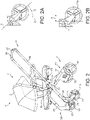
- the following gives an overview of the folding process, with reference to the various parts of Fig. 3 .
- the folding process involves the following sequence of steps:
- the present embodiment provides a stroller 1 capable of a convenient folding process in which both the foldable chassis 9 and bassinet 7 (or seat 3) may be folded without need to remove the bassinet 7 (or seat 5) from the foldable chassis 9, and in which the folding of the foldable chassis 9 and bassinet 7 (or seat 5) is performed in a single, integrated process. Additionally, the present embodiment further increases user convenience as the entire folding process may be conducted in a single-handed operation by the user, leaving the other hand free e.g. to hold the hand of an infant previously the passenger of the stroller 1.
- the bassinet 7 being also one embodiment of an independent foldable bassinet aspect of the present invention, is shown in greater detail in Figs. 4A and 4B and comprises a cushioned base plate 17, on which an infant may be placed, surrounded by peripheral side walls 18 formed from a foldable frame 19 covered by inner and outer layers of fabric 21, 23 (the fabric layers being shown in phantom in Fig. 4A ).
- the foldable frame 19 itself comprises a base frame 25 on which the base plate 17 is provided (the base frame 25 and the base plate 17 may be integrally formed as a single piece, such that the base frame 25 may be considered as part of the base plate 17) and to which bassinet joints 15 are slidably mounted on each lateral side by slotted mounting plates 27 (see Fig.
- first and second connecting arms 31, 33 on each lateral side of the bassinet 7.
- First (upper) ends of the connecting arms of each pair are pivotally mounted to a respective mounting sleeve 35 fixed to each lateral side of the upper frame 29 (see Fig. 5D ); second (lower) ends of the connecting arms 31, 33 are mounted to the joints 15.
- Feet 36 are provided on the underside of the base frame 25 to stabilise the bassinet 7 on the floor (or other support surface) when the bassinet 7 is used independently of the foldable chassis 9.
- Parasol, canopy and carry handle interfaces 37, 39, 41 are also provided on the upper frame 29 of the bassinet 7, and to which a parasol, canopy and carry handle (not shown) may be removably attached by a user.
- the joint 15 on a first lateral side of the frame 19 is shown in greater detail in Fig. 5 ; the joint 15 on the second lateral side of the frame 19 takes a corresponding configuration and hence is not described further.
- the joint 15 comprises a joint body 43 having on its outer surface a mounting portion 45, which in the present embodiment comprises a generally triangular-shaped recess with a rounded apex uppermost, which co-operates with a mounting portion on the corresponding joint of the foldable chassis (described below) to mount the bassinet 7 on the foldable chassis.
- Protrusions are provided on the reverse surface of the joint body 43, which fit into the laterally-extending slot 27a in the mounting plate 27, to slidably mount the joint body 43 relative to the bassinet frame 19.
- the second (lower) end of the first connecting arm 31 is pivotally mounted to the joint body 43 at pivot point 47.
- the second connecting arm is pivotally mounted to the joint body at pivot point 49.
- a bassinet locking lever 51 is biased into locking engagement with the second connecting arm 33, preventing the second connecting arm 33 from pivoting relative to the joint body 43.
- the bassinet locking lever 51 is provided with two laterally-extending protrusions 52a, 52b.
- the first of these protrusions 52a (see Fig. 5C ) is located at a first end 51a of the lever 51, distal from a pivotally mounted second end 51b, and is biased by a biasing element such as a spring (not shown) to protrude through and thus engage with an aperture 33a formed at the second (lower) end of the second connecting arm 33.
- the second of these protrusions 52b (see Fig. 5A ) is provided between the first and second ends of the lever 51, and extends through and thus engages with an aperture 43a in the joint body 43.
- the second connecting arm 33 is fixed in place relative to the joint body 43, as shown in Figs. 5A and 5B . Because the second connecting arm 33 is fixed in place relative to the joint body 43, the first connecting arm 31 and joint body 43 are likewise held in a fixed position relative to the other parts of the bassinet frame 19, meaning that the bassinet 7 is rigidly held in the unfolded condition shown in Fig. 4A .
- the bassinet locking lever 51 and the apertures in the second connecting arm and the joint body 33a, 43a may therefore together be seen as a bassinet locking mechanism, which acts to prevent unintended folding of the bassinet 7.
- the second laterally-extending protrusion 52b of the bassinet locking lever 51 defines a bassinet unlocking button 53 located to coincide with the position of the mounting portion 45. Pressing this button 53 causes the lever 51 to rotate in the direction of the arrow shown in Fig. 5C , against the bias of its associated biasing element, to move inwardly of the joint body 43. Sufficient pressure on the bassinet unlocking button 53 therefore disengages the second connecting arm 33 from the bassinet locking lever 51 and thus enables both the first and second connecting arms 31, 33 to pivot relative to the joint 15 and thus for the bassinet 7 to fold (see Figs. 5D and 5E ).
- the bassinet unlocking button 53 may be pressed either a) by a moving part of the foldable chassis 9 (specifically, the secondary fold actuator lever described below) when the bassinet 7 is mounted on the foldable chassis 9 - this corresponds to the folding process of Fig. 3 , or b) by a user, employing their finger or an appropriate tool, when the bassinet 7 is used independently of the foldable chassis 9 - this is the folding process of Fig. 6 , also discussed below.
- a bassinet-to-chassis mounting lock 55 and corresponding release button 57 are further provided on the joint body 43, as shown in Fig. 5A .
- the bassinet-to-chassis mounting lock 55 automatically engages with a corresponding part of the foldable chassis joint 13 when the bassinet 7 is mounted on the foldable chassis 9, to lock the bassinet 7 in place and prevent its inadvertent release. This locking engagement is released by pressing the release button 57, when it is desired to remove the bassinet 7 from the foldable chassis 9.
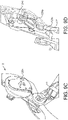
- the base frame of the foldable chassis 9 comprises front and rear frame portions 59, 61 which are hingedly connected to each other at pivot points 63 provided in each chassis joint 13, thus allowing the overall foldable chassis to fold. Locking mechanisms (described further below) are provided in each joint 13, to prevent inadvertent folding of the foldable chassis 9.
- the front frame portion 59 has a generally "U"-shaped configuration and is formed by two parallel front frame arms 65 joined in the vicinity of their forward ends (i.e. the ends distal of the pivot points 63) by a transverse strut 67.
- a "self stand” 69 employed during the folding process, is located centrally on the transverse strut 67.
- the forward ends of the front frame arms 65 each serve as a mounting point for a respective one of a pair of front wheels 71 of the stroller 1.
- the front wheels 71 are connected to the front frame arms 65 by stems 73, which are themselves pivotally mounted to forward ends of the front frame arms 65 by swivel joints 75, to allow the front wheels 71 to turn relative to the central longitudinal axis of the stroller 1 and thus give steerage.
- the stems 73 are configured to offset the hub 71a of each front wheel 71 (and therefore the centre of gravity of the wheel/stem combination) from its associated swivel joint 75, in the horizontal plane - this horizontal offset is labelled "X" in Fig. 2B .
- the hub 71a of each front wheel 71 is observed at a different location from the swivel joint 75 associated with that wheel 71, because the hubs 71a are not positioned directly underneath their respective swivel joints 75, but are instead horizontally offset from the swivel joints 75.
- the stems 73 are configured such that when the stroller 1 is pushed forward, the hub 71a of each front wheel 71 adopts a position which is horizontally offset to be rearward (closer to the rear wheels) than the swivel joint 75.
- the stems 73 may be shaped and/or configured in various ways to achieve this horizontally offset relationship between the centre of gravity of the wheel/stem combination and the swivel joint 75 of the stem 73, and the precise manner in which this relationship is achieved is not important, but in the present embodiment this relationship is achieved by providing elongate stems 73 each defining a longitudinal stem axis A (see inset Fig. 2A ) which is angled at non-zero angle ⁇ , relative to vertical Z, on the ground/lower side of the stem 73.
- this angle is not particularly important as long as the foregoing relationship is observed, but may for example be any non-zero, acute angle less than 90 degrees, preferably any acute angle greater than or equal to 10 degrees and less than or equal to 60 degrees, more preferably any acute angle greater than or equal to 20 degrees and less than or equal to 50 degrees, further more preferably any acute angle greater than or equal to 30 degrees and less than or equal to 40 degrees, and most preferably an angle of around 35 degrees.
- the rear frame portion 61 takes a generally "U"-shaped configuration formed by two parallel rear frame arms 77 joined in the vicinity of their rearward ends (i.e. the ends distal of the pivot points 63) by a transverse strut 79.
- the rearward ends of the rear frame arms 77 each serve as a mounting point for a respective one of a pair of rear wheels 81 of the stroller 1.
- a luggage storage area is provided underneath the bassinet/seat mounting area -this luggage storage area is shown in Fig. 21 and discussed in greater detail below.
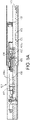
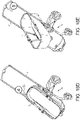
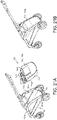
- the telescopic handle 11 comprises a pair of outer tubes 83 fixed relative to the front frame arms 65 and within which a pair of inner tubes 85 are slidable upon appropriate actuation of buttons located within a button housing 87 mounted centrally on a handle crossbar 89 which joins the two inner tubes, and which buttons are used in the present embodiment to initiate both handle height adjustment and folding of the stroller 1.
- the outer tubes 83 are fixed to and open into the (hollow) front frame arms 65, to permit the forward ends of the inner tubes 85 to penetrate forwards into the front frame arms 65 as the telescopic handle 11 is collapsed, before eventually exiting through apertures 91 in the front frame arms 65 when the handle 11 is fully collapsed, where they act to support the stroller 1 in its folded state (see Fig. 3E ).
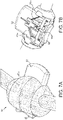
- the button housing 87 of the handle 11 is shown in greater detail in the various parts of Fig. 7 , in which an outer casing 87a of the housing 87 is shown in phantom in Fig. 7A , and omitted entirely in the remaining parts, for clarity of illustration.
- Housed within the button housing 87 are a primary handle adjustment button 93 and a secondary handle adjustment button 95, as well as a pair of movable sliding elements 97 which ride on respective angled inner faces 93a of the primary handle adjustment button 93.
- Each of the sliding elements 97 is attached via a cable (not shown) to a respective one of a pair of handle locking systems, one of which is shown generally at 101 in Fig. 8A .
- the handle locking system 101 is located within the handle 11 and is distributed over the outer/inner tube pair 83, 85 on one side of the handle 11.
- the other handle locking system is distributed over the other outer/inner tube pair on the other side of the handle 11 and is identical to that shown in the various parts of Fig. 8 .
- the handle locking system 101 chiefly comprises a series of indents 103 on the inner surface of the (fixed position) outer tube 83, as well as a movable locking height adjustment tab 105, a chassis fold tab 107 and chassis fold tab actuator 109 all provided on the (movable) inner tube 85 of the handle 11.
- the indents 103 correspond to a plurality of predetermined handle heights with which the locking height adjustment tab 105 may be selectively engaged, so as to fix the handle 11 at the desired height.
- the chassis fold tab 107 and chassis fold tab actuator 109 are used when the stroller 1 is being folded.
- the primary and secondary handle adjustment buttons 93, 95 and the sliding elements 97 are biased by respective biasing elements such as springs (not shown) into their initial positions shown in Figs. 7A and 7B
- the locking height adjustment tab 105 is similarly biased by a locking height adjustment tab biasing element such as a spring (not shown) to protrude outwardly into engagement with an initial position indent 103a, corresponding to an initial predetermined handle height, as shown in Fig. 8A .
- a user presses the primary handle adjustment button 93 into the button housing 87, which moves the sliding elements 97 towards each other as they slide on the angled inner faces of the primary handle adjustment button 93 (see Fig. 7C ).
- This movement of the sliding elements 97 pulls on the cables within the handle 11, which in turn results in the locking height adjustment tab 105 being retracted from engagement with the initial position indent 103a, thus releasing the handle 11 from fixture at its initial height position.
- the user may then move the handle 11 to another of the predetermined handle height positions and release the primary handle adjustment button 93, causing the sliding elements 97 to return to their initial positions under bias of their respective biasing elements (not shown).
- the extent of movement of the primary handle adjustment button 93 into the button housing 87 (and therefore the amount by which the cables are pulled by the sliding elements 97) is limited by a projection 95a of the secondary handle adjustment button 95, which acts as an end stop by coming into contact with a corresponding projection 93b provided on the primary adjustment handle 93.
- the user When folding the stroller 1, the user additionally actuates the secondary handle adjustment button 95, by sliding it laterally to a position at which the projections 93a, 95a are not aligned and so do not come into contact, as shown in Figs. 7D and 7E .
- This increases the range of movement of the primary handle adjustment button 93 into the button housing 87, and therefore increases the amount by which the cables are pulled by the sliding elements 97.
- This further pulling of the cables causes an inclined face 109a of the chassis fold tab actuator 109 to contact the chassis fold tab 107, forcing it to protrude outwardly from the inner tube 85 (as shown in Figs. 8B and 8C , discussed below).
- the protruding chassis fold tabs 107 of the handle locking systems 101 are then used to unlock locking mechanisms in each of the chassis frame joints 13 (described in greater detail hereinafter), which then allows the foldable chassis 9 to start folding. It will therefore be understood that, by governing this operation, the secondary handle adjustment button 95 acts as a safety mechanism which prevents inadvertent folding of the stroller 1.
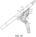
- Figs. 9 to 13 show a first of the two chassis frame joints 13, which is located on a first side of the foldable chassis 9; the second of the two joints 13, on the other side of the foldable chassis 9, takes the same configuration.
- Each joint 13 comprises a joint housing 111 fixed to the outer tube 83 of the handle 11 (and therefore also fixed relative to the front frame potion 59 of the foldable chassis 9) and in which various joint components are contained, as well as the above-mentioned pivot point 63 which serves as the hinged connection between the front and rear frame portions 59, 61.
- a mounting portion 115 which in the present embodiment takes the form of a generally triangular-shaped protrusion with a rounded apex uppermost, is formed on the outer surface of the joint housing 111 for co-operation with the mounting portion 45 of the corresponding bassinet joint 15, to support and secure the bassinet 7 in place on the foldable chassis 9.
- An aperture 117 is located to coincide with the position of the mounting portion 115, and in particular to coincide with the location of the bassinet unlocking button 53 in the bassinet joint 15 when the bassinet 7 is supported on the foldable chassis 9. As discussed further below, this enable the bassinet unlocking button 53 to be pressed automatically when the foldable chassis 9 is being folded, thus allowing the bassinet 7 to fold also.
- a pivotally-mounted chassis unlocking lever 119 (see figs. 10 and 11 ), a locking beam 121 (see Fig. 10 ), a locking beam track 123 formed on an internal face of the joint housing 111 (see Fig. 10 ), and a secondary fold actuator lever 125 which rides on a cam surface 127 formed on the rear frame portion 61 (see Figs. 9B and 9D ).
- the locking beam 121 has a floating first end 121a provided with a protrusion 121b and a second end 121c which is pivotally mounted to the upper end of the rear frame portion 61.
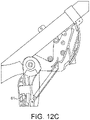
- the locking beam 121 adopts the initial position shown in Fig. 12A .
- the protrusion 121b seats within an unfolded condition locking indent 123A at a first (upper) end of the locking beam track 123, thus fixing the rear frame portion 61 in position relative to the handle 11 and front frame portion 59.
- the locking beam 121 and locking beam track 123 therefore act as a chassis locking mechanism, holding the foldable chassis 9 in its unfolded state until a user choses to fold the stroller 1.
- the locking beam 121 is additionally connected to the self stand 69 by a cable 129 (see Figs. 13B and 13D ).
- the self stand 69 is movable between a retracted condition (see figs. 13A and 13B ) and an extended condition (see Figs. 13C and 13D ).
- a biasing element such as a spring (not shown) acts to bias the self stand 69 into the extended condition.
- tension is applied to the cable when the locking beam 121 is in its initial position of Fig. 12A , meaning that the self stand 69 is held in its retracted condition when the stroller 1 is unfolded.
- a user In order to fold the stroller 1, a user first actuates the secondary handle adjustment button 95 in the button housing 87, by sliding it laterally to the position shown in Fig. 7D , and depresses the primary handle adjustment button 93 to the extended position shown in Fig. 7E .
- This is the initial step shown in Fig. 3A , discussed earlier.
- these actions disengage the locking height adjustment tab 105 from the indents 103 on the outer tube 83, enabling the telescopic handle 11 to start to collapse (see fig. 3B ), and cause the chassis fold tab 107 to protrude outwardly from the inner tube 85.
- the downward force applied by the chassis fold tab 107 causes the chassis unlocking lever 119 to pivot such that it contacts the first (upper) end of the locking beam 121 (see Fig. 11B ).
- This contact unseats the locking beam 121 from the unfolded condition locking indent 123a, thus releasing the rear frame portion 61 from its fixed position relative to the telescopic handle 11 and front frame portion 59.
- the user now simply tilts the stroller 1 forward using the handle 11 (see arrow in Fig. 3C ), thus lifting the rear end of the stroller 1 such that the (unlocked) rear frame portion 61 swings forward under gravity, towards the front frame portion 59, and so starting to fold the foldable chassis 9.
- the second (lower) end of the locking beam 121 is pivotally mounted to the rear frame portion 61, it is pulled downwardly along the locking beam track 123 by the folding movement of the rear frame portion 61 (see Figs. 12B and 12C ).
- This downward movement of the locking beam 121 releases the tension on the cable 129, enabling the self stand 69 to adopt its extended condition (see Figs. 13C and 13D ).
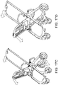
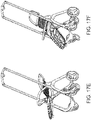
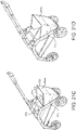
- the self stand 69 extends and comes into contact with the ground surface, resulting in the front wheels 71 being lifted from the ground surface, as shown in the folding sequence in Figs. 17F to 171 (albeit there shown with the seat 5 attached to the foldable chassis 9 in place of the bassinet 7). Friction between the self stand 69 and the ground surface assists with tilting the stroller 1 further forward.
- the front wheels 71 are free to rotate around their respective swivel mounts 75 (see Figs. 17F to 171 ).
- the initial horizontal offset X of the centre of gravity of each front wheel/stem combination from its associated swivel mount 75 gives rise to a turning moment about the swivel mount 75 as the stroller 1 is tilted forward and the front wheels 71 are lifted from the ground. This causes the wheel/stem combinations to flop forwardly under gravity (see Figs.
- the folding of the foldable chassis 9 also unlocks the bassinet 7 from its unfolded condition.
- the secondary fold actuator lever 125 (and more specifically, a first end 125a thereof) rides on a cam surface 127 formed on the rear frame portion 61. It will therefore be appreciated that the forward movement of the rear frame portion 61, as it folds forwardly, results in movement of the secondary fold actuator lever 125 governed by contact between the first end 125a of the secondary fold actuator lever 125 and the cam surface 127.
- the movement of the secondary fold actuator lever 125 results from the folding movement of the rear frame portion 61 (and the rear wheels 81 mounted to the rear frame portion 61), as it swings forward under gravity.
- the rear frame portion 61 and rear wheels 81 are relatively heavy, a significant motive force is therefore transmitted to the secondary fold actuator lever 125 via the cam surface 127, readily overcoming any friction between the cam surface 127 and the secondary fold actuator lever 125 and providing a firm and reliable actuation of the bassinet unlock button 53.
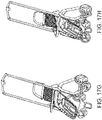
- the user applies further downward pressure on the telescopic handle 11, resulting in the stroller 1 adopting its fully folded condition as shown in Fig. 3E , ready e.g. for convenient transport or storage of the folded package.
- the stroller 1 is stabilised in its folded condition by the forward ends of the telescopic handle 11, which protrude through apertures in the lower side of the folded foldable chassis 9 to support the stroller 1 on the floor (or other support) surface, in tandem with the rear wheels 81 of the stroller 1.
- a user need only perform the following actions to fully collapse the stroller 1, including the foldable chassis 9 and the bassinet 7 mounted on the foldable chassis 9: (i) actuate the primary and secondary buttons 93, 95 of the button housing 87 to release the handle 11 (ii) depress the handle 11 while tilting the stroller 1 forward, causing both foldable chassis 9 and bassinet 7 to fold under gravity and iii) continue to press downwardly on the handle 11 until it is fully collapsed.
- Similar considerations apply also to the collapse of the stroller when in the "seat facing world" or “seat facing parent” configurations.
- the present embodiment is further convenient as a user may simply and readily perform each of the three operations i) to iii) discussed above (and thus fully collapse the stroller 1, from any of the three configurations shown in Fig. 1 ) by grasping the handle 11 and operating the button housing 87 with a single hand, leaving the other hand of the user free e.g. to hold the hand of a child previously the passenger of the stroller 1.
- the stroller 1 of the present embodiment additionally includes releasable locking mechanisms associated with both the handle 11 and the foldable chassis 9 which advantageously retain the stroller 1 in its folded condition until a user wants to unfold it.
- the present embodiment also includes a handle locking mechanism to ensure that the handle 11 is prevented from full collapse until an appropriate time in the folding process.
- the latter handle locking mechanism is more relevant to the stroller with (forward/reverse facing) seat configurations, and hence is described further below in connection with those configurations.
- the releasable locking mechanisms used to retain the stroller 1 in its folded condition are described in the following.
- each of the handle locking mechanisms 101 provided within the handle 11 further comprises a handle locking tab 131 mounted on the (slidable) inner tube 85 of the handle 11.
- the handle locking tab 131 is the same in each case, and hence only one is described here.
- the handle locking tab 131 is biased to protrude outwardly by spring-loaded resilient element 133.
- the handle locking tab 131 engages with an end stop indent 135 provided on the (fixed) outer tube side - see fig. 14B .
- the handle 11 is now locked in its fully collapsed condition, and the user can conveniently lift and move the folded stroller 1 using the handle 11 in this state, without the stroller 1 unfolding.
- the user simply need actuate the primary handle adjustment button 93 of the button housing 87, which pulls on the cables (not shown) within the handle 11 and acts to lift the handle locking tab 131 out of engagement with the end stop indent 135, against the bias provided by the spring-loaded resilient element.
- the user may then extend the handle 11 once more to unfold the stroller 1 (the full unfolding process is further discussed below).
- the locking beam track 123 in addition to the unfolded condition locking indent 123a at its upper end, also includes a pair of folded condition locking indents 123b, 123c at its lower end.
- the first of these (123b) is slightly higher up the track 123 than the second, and is for use when luggage or articles present in a storage area of the stroller 1 underneath the bassinet/seat prevents the stroller 1 from being placed into its most folded compact condition, which corresponds to the lowest folded condition locking indent 123c.
- the chassis joint 13 is further provided with a folded chassis release lever 137, shown in the various parts of Fig. 15 .
- a folded chassis release lever 137 shown in the various parts of Fig. 15 .
- the bassinet 7 is usable independently of the foldable chassis 9.
- a user may disengage the bassinet 7 from the foldable chassis 9 and use it in a nursery or other room, locating the bassinet 7 on the floor or other suitable support surface instead of on the foldable chassis 9.
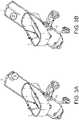
- a user With the bassinet 7 empty, a user first presses the bassinet unlocking button 53 of each bassinet joint 15, using either their fingers or a suitable pressing tool, to release the locking engagement of the bassinet frame 19 and joints 13 (see Fig. 6A ). The user then presses downwardly and forwardly on the upper frame 25 (see arrow in Fig. 6B ), to encourage the first and second connecting arm pairs 31, 33 of the bassinet frame 19 to start to pivot. Continued vertical downward pressure on the upper frame 29 (see arrow in Fig.
- the bassinet 7 collapses the bassinet 7 entirely, with the bassinet joints 15 sliding rearwardly to absorb longitudinal movement of the pivoting connecting arms 31, as described above, to allow the upper frame 29 to collapse directly downward onto the base frame 25 and provide a compact folded footprint.
- the feet 36 on the underside of the base frame provide sufficient ground clearance for the joints 15 and pivoting connecting arms 31, 33 to move freely throughout the fold process, without touching the floor surface (or other support surface e.g. table top).
- a user need simply lift the upper frame 29, causing the joints 15 and first and second connecting arm pairs 31, 33 to move back towards their initial positions, until the bassinet locking lever 51 of each joint re-engages with its corresponding second connecting arm, preferably with an audible "click", to hold the bassinet 7 in its unfolded condition once more.
- bassinet aspect of the present invention may equally be applied to bassinets which are not adapted to be mounted on strollers and are instead solely intended for stand-alone use. Therefore, embodiments of the independent bassinet aspect of the present invention extend beyond stroller-mountable bassinets to stand-alone bassinets not being configured for mounting on a stroller frame or similar.
- the stroller with seat facing world/facing parent configurations will now be described, which similarly may be folded without removing the seat from the chassis frame in a single interconnected process, and in the present embodiment may advantageously be folded with a one-handed user operation.
- Figs. 17 an 18 show the stroller 1 being placed into the folded condition from its "seat facing parent" and “seat facing world” configurations, respectively.
- the folding process is similar to that for the "stroller with bassinet" configuration, in that folding of the foldable chassis 9 of the wheeled chassis 3 results in the secondary fold actuator levers 125 of the frame joints 13 disengaging locking mechanisms within the joints on either side of the seat 5, which in turn enables the seat 5 to fold under gravity as the stroller 1 is tilted forward.
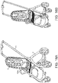
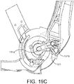
- the following discussion focusses on the joint of the seat 5, which is shown in the various parts of Fig. 19 ; as with the bassinet 7, the joints on either side of the seat 5 are identical to each other and hence only one of them will be described.
- the seat 5 comprises a squab or base frame 139 (of which only the part closest to the joint is shown in the figure), a reclinable seat back frame 141 (of which again only the part closest to the joint is shown in the figure) and a "bumper bar" socket 143, all joined by a central seat joint 145.
- the seat back frame 141 is releasably engageable with the joint 145, either to rotate around the central seat joint 145 when released to enable the seat 5 to be folded, or to be held in fixed position relative to the seat joint 145 when engaged, so as to place the seat 5 into a fixed upright or reclining position for a child to sit or recline on.
- the bumper bar socket 143 is initially connected to the seat back frame 141 by a releasable connection (not shown), and so rotates with movement of the seat back frame 141.
- the base frame 139 is free to rotate around the joint 145, but is supported in its generally horizontal position shown in Figs. 19A to 19C , when the stroller 1 is unfolded, by resting on the horizontal upper surface 146a of a boss 146 formed on each side of the rear frame portion 61 - see Fig. 11A .
- a seating portion (whether cushioned surface, netting or similar) is provided on the base frame 139, for the stroller passenger to sit on.
- the seat back frame 141 similarly mounts a seat back (whether cushioned surface, netting or otherwise) for the stroller passenger to lean back on.
- the bumper bar socket 143 allows a bumper bar to be removably attached to the seat 5.
- the bumper bar is omitted in the present figures, for clarity, but an example of a bumper bar 143a is shown mounted to the seat 5 in the various parts of Figs. 17 and 18 .
- this bar 143a provides an element of safety by helping retain a child in the seat 5 (in addition to any seat harnesses (not shown) which may be provided), gives a child a rail to hold on to when the stroller is in use, and further provides a user with an additional handle to assist in manipulating the stroller e.g. when loading the folded stroller into a vehicle after use.
- the seat joint 145 externally the seat joint 145 comprises a generally cylindrical joint housing 146 having on its circular end face surface a mounting portion 147, which in the present embodiment comprises a generally triangular-shaped recess with a rounded apex uppermost, for co-operation with the mounting portion 115 on the corresponding joint 13 of the foldable chassis 9 to mount the seat 5 on the foldable chassis 9.
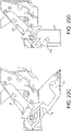
- An aperture 149 is located at the centre of the circular end face of the joint housing 146. As further explained below, this enables the secondary fold actuator lever 125 of the foldable chassis joint 13 to contact a first end 151a of a seat locking element 151 located within the seat joint 145 and thus release the seat 5 for folding.
- the seat locking element 151 is shown in Fig.
- Each of the apertures 153a of the seat recline position selector 153 corresponds to a predetermined recline position of the seat back 141.
- the engagement between the protrusion 151b and the seat recline position selector 153 holds the seat back 141 in fixed position relative to the joint 145, at one of the predetermined recline positions.
- a handle (not shown) is provided at the top of the seat back frame 141, and is connected to the second end of the seat locking element 151 by a cable (not shown).
- a user simply pulls on the handle to disengage the protrusion 151b from the aperture 153a in the seat recline position selector 153; the seat back may then be rotated relative to the joint 145 to another of the predetermined seat back recline positions, where the protrusion 151b will engage once more with the seat recline position selector 153 at the aperture 153b corresponding to the new seat back position.
- the secondary fold actuator lever 125 of the chassis joint 13 is able to contact the first end 151a of the seat locking element 151 via the aperture 149. This contact also releases the seat back frame 141 to rotate around the seat joint 145 as part of the seat folding process, as pressing the first end 151a of the seat locking element 151 causes the seat locking element 151 as a whole to move inwardly of the joint housing 146, thus disengaging the protrusion from the seat recline position selector 153.
- the seat locking element 151 and the seat recline position selector 153 may therefore together be considered as a seat joint locking mechanism.
- the aperture 149 and the first end of the seat locking element 151 are centrally located on the end face of the joint housing 146.
- the actuation mechanism is kept simple, without need for different actuation processes depending upon the seat orientation.
- the stroller folding process is similar, mutatis mutandis, to that for the bassinet configuration - by suitably manipulating the buttons 93, 95 of the button housing 87, a user starts to collapse the stroller frame handle 11 with the chassis fold tabs 107 protruding outwardly from the inner tubes 85 of the handle 11, which in turn actuates the chassis unlocking levers 119 of each chassis joint 13 (see Figs. 11A and 11B ) to unseat the locking beam 121 from the unfolded condition locking indent 123a, thus releasing the rear frame portion 61 from its fixed position relative to the telescopic handle 11 and front frame portion 59.
- the folding of the rear frame portion 61 towards the front frame portion 59 again causes the secondary fold actuator lever 125 to move, as governed by contact between the first end of the secondary fold actuator lever 125 and the cam surface 127 on the rear frame portion 61, such that the second end of the secondary fold actuator lever 125 moves towards and ultimately protrudes through the aperture 117 formed in the joint housing 111, this time to press the first end 151a of the seat locking element 151 and thus release the seat back frame 141 to rotate freely around the joint under gravity, as the stroller 1 is tilted forward by the user.
- the seat back frame 141 is free to rotate both clockwise and anticlockwise around the joint 145. Therefore, in the "facing parent" configuration of Fig.
- the reclined seat back falls back (see Figs. 17C to 171 ) to adopt a generally downwardly facing condition in the folded stroller (see Fig. 17J ).
- the reclined seat back rotates forward, again to adopt a generally downwardly facing condition in the folded stroller.
- a releasable connection (not shown) is initially present between the bumper bar socket 143 and the seat back frame 141, meaning that the bumper bar socket 143 (and hence the bumper bar mounted in the socket) initially rotates around the seat joint 145 together with the seat back frame 141.
- This releasable connection is released (e.g. by a projection, not shown) when the seat back frame 141 is close to its final downward facing position, meaning that the bumper bar socket 143 can then rotate further around the seat joint 145, relative to the seat back frame 141, to adopt a position closer to the seat back frame 141 (i.e. reducing the angle ⁇ shown in Fig. 19A ), reducing the dimensions of the folded seat still further.
- the folding movement of the rear frame portion 61 means that the upper surface 146a of the boss 146, which initially supports the seat base frame 139 to be horizontal (see fig. 12A ), moves downwardly (see Fig. 12B ), allowing the seat base frame to rotate around the joint to eventually point generally vertically downward, as shown in Fig. 18H .
- the foldable stroller 1 may also be conveniently folded by a user from either of its "seat facing parent" or “seat facing world” configurations, without need to remove the seat 5 from the foldable chassis frame 9 and without the user having to perform separate folding operations for the foldable chassis frame 9 and the seat 5.
- the stroller 1 of the present embodiment is further beneficial in that it may be placed into its folded condition with a simple one-handed operation from the user, leaving their other hand free e.g. to hold the hand of a child previously the passenger of the stroller 1.
- the present embodiment further includes a handle locking mechanism to ensure that the handle 11 is prevented from full collapse until an appropriate time in the stroller folding process.
- a handle locking mechanism to ensure that the handle 11 is prevented from full collapse until an appropriate time in the stroller folding process.
- the seat base frame 139 and bumper bar carried by the bumper bar socket 143 rotate around the seat joint 145 to move from one side of the handle 11 to the other, passing under the cross bar 89 of the handle 11 as they do so (see Figs. 17E to 171 ).
- the handle locking mechanism is primarily intended to prohibit the handle 11 from interfering with this rotation of the seat back 141 or seat base 139 i.e. to avoid trapping the seat back or base on the "wrong" side of the handle 11, before they have adopted their fully folded conditions. It will however be appreciated that this mechanism may also be useful e.g. in preventing interference between the handle and the folding bassinet 7, particularly where the bassinet 7 has high side walls.
- the handle locking mechanism is shown generally at 155 and comprises a generally "T"-shaped movable handlebar locking element 157 which is pivotally mounted to the chassis frame joint 13 at a first end 157a and has a blocking protrusion 157b and a contact protrusion 157c at opposed extremities of its second end.
- the contact protrusion 157c rides on a curved surface 159 formed on the rear frame portion 61.
- the foldable chassis 9 is itself nearly or fully in its folded condition, meaning that the seat 5 (or bassinet 7) supported on the foldable chassis 9 can also be assumed to be nearly or fully in its folded condition. Hence, full collapse of the handle 11 (which could otherwise interfere with folding of the seat 5 or bassinet 7) it prevented until an appropriate point in the folding process.
- the wheeled chassis 3 of the above embodiment includes a luggage storage area 161 underneath the seat/bassinet mounting point (seat and bassinet omitted in Fig. 21 for clarity of illustration of luggage storage area).
- the luggage storage area 161 comprises a generally horizontal support surface 161a on which luggage or other items may be placed and two lateral side walls 161b to help retain the luggage/items on the support surface 161a, all extending between the front and rear frame portions 59, 61 of the foldable chassis 9 at a position below the seat/bassinet mounting point.
- the transverse strut 79 of the rear frame portion 61 also helps retain items on the support surface 161a, and hence also forms part of the luggage storage area 161.
- the luggage storage area 161 is foldable in sympathy with the foldable chassis 9. In the present embodiment, this is achieved by forming the horizontal support surface 161a and lateral side walls 161b of the luggage storage area 161 from a flexible material e.g. foldable cloth fabric or netting, although other examples are possible e.g. the luggage storage area 161 may comprise suitably hinged panels, so as not to interfere with the folding of the foldable chassis 9.
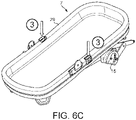
- a luggage item 163 configured for placement on the luggage storage area 161 and which in the present embodiment takes the form of a bag.
- the bag 163 has front and rear panels 165, side panels 167 and one or more openings 169 to provide one or more cavities or compartments for storing articles within the bag 163.
- the bag 163 further preferably comprises carry handles 171.
- the bag 163 of the present embodiment may be understood as a generally conventional "tote" style bag.
- the bag 163 further comprises non-conventional features.
- connection elements 172a (of which only one is shown in fig. 21A ; a second is provided at a corresponding position on the other side of the bag 163) are provided on either lateral side of the bag 163, for forming a releasable connection with corresponding connection elements 172b (again, only one shown) provided on either lateral side at the rear of the foldable chassis 9.
- the connection elements 172 a,b comprise co-operating magnetic pieces.
- the co-operating connection elements 172a,b may comprise a pair of magnets which are attracted towards each other, or one of the pair of co-operating connection elements 172a,b (for example, each of the connection elements 172b on the foldable chassis 9) may be a magnet and the other (each of the connection elements 172a provided on the bag 163) may comprise a portion of magnetic material e.g. a piece of ferromagnetic material such as iron or steel which is strongly attracted to the magnet.
- the magnetic connection element 172a is provided on the exterior of the bag 163 of the present embodiment, it may be covered e.g. hidden under the fabric of the side panel of the bag 163, so long as the force of magnetic attraction between the connection elements 172a, 172b remains strong enough to form a reliable, releasable connection between the bag 163 and foldable chassis 9.
- connection elements 172a of the bag 163 may also take other forms e.g. co-operating popper and socket, patches of hook and loop material (e.g. Velcro (RTM)), or any other suitable releasable attachment means.
- connection elements may also take other forms e.g. co-operating popper and socket, patches of hook and loop material (e.g. Velcro (RTM)), or any other suitable releasable attachment means.
- connection element Regardless of the type of connection element used, it will be appreciated that releasably attaching the luggage bag 163 to the rear of the foldable chassis 9 is beneficial, as this means that the bag 163 (and hence its contents) is still accessible to a user when the stroller 1 is folded - as shown in figs. 3E and 17G , the rear frame portion 61 is rearmost when the stroller 1 is folded, hence keeping the bag 163 accessible at the rear of the folded stroller 1. It will also be appreciated that mounting the bag 163 to the rear frame portion 61 beneficially also enables ready access to the bag 163 and its contents when the stroller 1 is in its unfolded condition, as shown in Figs. 21B to 21D .
- the bag 163 is specifically configured (sized and shaped) to co-operate with the foldable chassis 9 and luggage area 161, and in particular is of a suitable width to bridge the gap between the lateral sides of the rear frame portion 61. This is beneficial, as when the bag 163 is placed on the luggage storage area 161 it acts as an additional rear retaining wall, helping to retain other items or luggage present on the horizontal support surface 161a. Additionally, the co-operating bag width ensures that the connection elements 172a on the bag 163 are automatically and conveniently positioned in close proximity with the corresponding connection elements 172b on the chassis 9 when the bag 163 is placed on the luggage storage area 161.
- the side panels 167 of the bag 163 are provided with additional material 173 (see Figs. 21C, 21D ) at the join between the side panels 167 and the front panel 165a, which allows the bag (and hence its storage capacity) to be expanded.
- the bag 163 is further provided with releasable attachments such as poppers, zips or the like (not shown) which provide a releasable connection between the unexpanded side panels 167 and the front panel 165a.
- the releasable attachments When fastened, the releasable attachments keep the front panel 165a in fixed position relative to the unexpanded side panel 167, with the extra material of the side panel 167 kept folded within the body of the bag 163; a user simply releases the attachments to allow the bag 163 to be expanded.
- expanding the bag 163 creates a larger opening and hence facilitates placement and removal of items into/from the bag 163, when the bag 163 is mounted on the foldable chassis 9.
- vertical zips 175 (of which one is shown in fig. 21C ) are used to connect the side panels 167 to the rear panel 165b of the bag.
- these zips are kept fastened, thus keeping the side 167 and rear 165b panels in fixed relation.
- the user may undo these zips to lower the rear panel 165b of the bag to lie flat on the horizontal support surface 161a, such that the luggage storage area 161 effectively extends into and includes the luggage storage area provided by the bag 163.
- This is particularly beneficial when the side panels 167 of the bag 163 are in their extended condition, as shown in Fig. 21D , as this maximises the available luggage storage area.
- luggage item 163 is described in connection with the folding stroller 1 of the foregoing embodiment, it will be appreciated that the luggage item 163 may be applied also to non-folding strollers having an underslung luggage storage area.
- the stroller 1 may be placed into the various configurations of Fig. 1 by providing a wheeled chassis 3 with a removable and repositionable seat 5 and bassinet 7.
- the stroller need not be provided with this level of adaptability, particularly where a simpler or lower-cost device is preferred.
- the stroller may be provided with just one of a seat or bassinet, and further, that seat or bassinet may or may not be removable from the wheeled chassis.
- the chassis locking mechanism is contained within the chassis joint housing 111, and the bassinet and seat locking mechanisms are contained within the bassinet and seat joints 15, 145, respectively.
- the chassis locking mechanism may be provided in whole or in part by components carried by the bassinet or seat or other part of the stroller, including by the chassis handle, and similarly the bassinet and seat locking mechanisms may be provided in whole or in part by components carried by the foldable chassis or other part of the stroller, including by the chassis handle.
- movement (collapse) of the handle 11 releases the foldable chassis 9 to fold, and the folding movement of the chassis 9 releases the seat 5 or bassinet 7 to fold.
- movement (collapse) of the handle instead releases a bassinet/seat locking mechanism, to permit the bassinet/seat to fold under gravity as the stroller is tilted forward.
- the folding of the bassinet/seat in turn releases a chassis locking mechanism to then also allow the chassis frame to fold under gravity; it will therefore be understood that in this modification the action of the joint between the bassinet/seat and the chassis frame is effectively reversed such that the folding action of the bassinet/seat is what releases the locking mechanism of the chassis frame.
- the embodiment described above may be modified such that movement of a first of any one of the chassis frame, bassinet/seat or handle from its unfolded/extended condition towards its folded/collapsed condition releases the locking mechanism of a second of those components, to enable the second of those components to move towards its folded/collapsed condition, and movement of the second of those components towards its folded/collapsed condition releases the locking mechanism of the third of those components to enable the third of those components to move to its folded/collapsed condition.
- movement of a first of any one of the chassis frame, bassinet/seat or handle from its unfolded/extended condition towards its folded/collapsed condition releases the locking mechanisms of both the second and third of those components, either simultaneously or sequentially, to enable the second and third of those components to also move to their folded/collapsed conditions.
- a user first collapses the handle, which movement simultaneously or sequentially releases the chassis locking mechanism and bassinet/seat locking mechanism, to permit chassis and bassinet/seat to fold under gravity as stroller is tilted.
- references to a "stroller” are to be interpreted as including prams, buggies and pushchairs. Also, although a stroller embodiment intended for a child or infant is described above, it will be appreciated that aspects of the present invention may be applied to a wheelchair for a child or adult. References to a "stroller” are therefore also to be interpreted as including wheelchairs for children or adults.
- the side panels may be provided with additional material at their joint with the rear panel to allow the rear panel to move downwardly into the luggage storage area to lie flat on the horizontal support surface.
- this modification also results in the luggage storage area effectively extending into and including the luggage storage area provided by the bag.
- the additional material at the sides, linking to the rear panel may beneficially assist in retaining items laterally on the luggage storage area.
Landscapes
- Engineering & Computer Science (AREA)
- Chemical & Material Sciences (AREA)
- Combustion & Propulsion (AREA)
- Transportation (AREA)
- Mechanical Engineering (AREA)
- Health & Medical Sciences (AREA)
- Public Health (AREA)
- Carriages For Children, Sleds, And Other Hand-Operated Vehicles (AREA)
Applications Claiming Priority (1)
| Application Number | Priority Date | Filing Date | Title |
|---|---|---|---|
| NL2027160A NL2027160B1 (en) | 2020-12-18 | 2020-12-18 | Foldable stroller, foldable bassinet, foldable seat, stroller and stroller and luggage system |
Publications (3)
| Publication Number | Publication Date |
|---|---|
| EP4026751A2 true EP4026751A2 (de) | 2022-07-13 |
| EP4026751A3 EP4026751A3 (de) | 2022-09-21 |
| EP4026751B1 EP4026751B1 (de) | 2024-07-03 |
Family
ID=74125653
Family Applications (2)
| Application Number | Title | Priority Date | Filing Date |
|---|---|---|---|
| EP21215288.8A Active EP4015347B1 (de) | 2020-12-18 | 2021-12-16 | Zusammenklappbarer kinderwagen, zusammenklappbare wiege, zusammenklappbarer sitz, kinderwagen sowie ein kinderwagen- und gepäcksystem |
| EP21215303.5A Active EP4026751B1 (de) | 2020-12-18 | 2021-12-16 | Zusammenklappbarer kinderwagen mit zusammenklappbarer wiege |
Family Applications Before (1)
| Application Number | Title | Priority Date | Filing Date |
|---|---|---|---|
| EP21215288.8A Active EP4015347B1 (de) | 2020-12-18 | 2021-12-16 | Zusammenklappbarer kinderwagen, zusammenklappbare wiege, zusammenklappbarer sitz, kinderwagen sowie ein kinderwagen- und gepäcksystem |
Country Status (5)
| Country | Link |
|---|---|
| US (2) | US12337891B2 (de) |
| EP (2) | EP4015347B1 (de) |
| CN (2) | CN114715250B (de) |
| ES (2) | ES2986995T3 (de) |
| NL (3) | NL2032195B1 (de) |
Cited By (1)
| Publication number | Priority date | Publication date | Assignee | Title |
|---|---|---|---|---|
| WO2025161241A1 (zh) * | 2023-12-12 | 2025-08-07 | 昆山威凯儿童用品有限公司 | 一种可快速打开收合的折叠提篮 |
Families Citing this family (4)
| Publication number | Priority date | Publication date | Assignee | Title |
|---|---|---|---|---|
| CN114348097B (zh) * | 2020-10-13 | 2023-06-16 | 明门(中国)幼童用品有限公司 | 菜篮避让机构与婴儿车架 |
| US20240017759A1 (en) | 2020-12-21 | 2024-01-18 | Wonderland Switzerland Ag | Child carriage with linkage for transitioning the child carriage to a folded configuration |
| CN116176680B (zh) * | 2021-11-29 | 2025-04-25 | 明门(中国)幼童用品有限公司 | 乘用装置 |
| KR102804584B1 (ko) * | 2023-05-18 | 2025-05-09 | 조남희 | 탈착식 펫전용 다목적함 |
Family Cites Families (104)
| Publication number | Priority date | Publication date | Assignee | Title |
|---|---|---|---|---|
| CA636176A (en) * | 1962-02-06 | Alfred N. Alsop | Sliding catch locking means for baby carriages | |
| NL3285C (de) * | 1916-09-30 | 1919-06-02 | ||
| GB306989A (en) * | 1927-11-30 | 1929-02-28 | Walter Lines | Improvements relating to folding perambulators, baby carriages and the like |
| GB376159A (en) * | 1931-11-24 | 1932-07-07 | George Horatio Curzon | Improvements in perambulators |
| US2174268A (en) * | 1938-07-11 | 1939-09-26 | Kroll Samuel | Carriage |
| US2488450A (en) * | 1944-10-09 | 1949-11-15 | Underwoods Patents Ltd | Collapsible perambulator |
| DE1580196A1 (de) * | 1967-04-13 | 1971-03-04 | Peggy Muenchner Kinderwagenfab | Kinderwagen |
| IT951443B (it) * | 1972-04-15 | 1973-06-30 | Kinder Baby Sas | Culla porta bambino elasticamente posizionabile in posizioni di lavoro |
| ES227893Y (es) * | 1977-03-31 | 1977-12-16 | Coche-silla infantil plegable, mejorado. | |
| DE8418222U1 (de) * | 1984-06-15 | 1984-10-25 | Hauck KG, 8625 Sonnefeld | Faltkinderwagen |
| FR2566357B1 (fr) * | 1984-06-22 | 1988-04-08 | Ampafrance | Poussette pliante pour enfant |
| DE3935108A1 (de) * | 1989-10-21 | 1991-04-25 | Hofmann Josef Metallwaren Kg | Kinderwagengestell |
| US5472224A (en) * | 1992-04-04 | 1995-12-05 | Jane, S.A. | Foldable baby carriage frame and cradle seat couplable to same |
| FR2780932B1 (fr) * | 1998-07-08 | 2000-09-22 | Ampafrance | Poussette pliante pour enfant, a memorisation de l'inclinaison du hamac |
| US6375213B1 (en) * | 1999-09-27 | 2002-04-23 | Combi Corporation | Stroller |
| CN2507335Y (zh) * | 2001-11-28 | 2002-08-28 | 秦正江 | 拆装折叠式儿童床 |
| GB0315684D0 (en) * | 2003-07-04 | 2003-08-13 | Cooper Howard L | A child support arrangement |
| GB2419520B (en) * | 2004-09-28 | 2008-04-09 | Armon Ltd | Convertible seat for a baby buggy |
| DE202005014143U1 (de) * | 2005-09-07 | 2005-12-01 | Joh. Georg Hartan | Tragetasche für ein Kind oder eine Puppe sowie Kinder- oder Puppenwagen |
| DE202005019191U1 (de) * | 2005-12-08 | 2006-02-16 | Beger, Udo | Umwandelbarer Sitz-Liegeeinsatz für Kinder- oder Puppenwagen |
| SE0601301L (sv) * | 2006-06-14 | 2007-10-23 | Europ Nursery Group Sweden Ab | Ligginsats |
| US8128119B2 (en) * | 2007-07-31 | 2012-03-06 | Graco Children's Products Inc. | Stroller with foldable frame and adjustable handle |
| CN101224753A (zh) * | 2007-12-19 | 2008-07-23 | 沈被久 | 儿童推车 |
| SE532037C2 (sv) * | 2008-02-29 | 2009-10-06 | Brio Ab | Barnvagn med hopfällbart chassi |
| FR2931432B1 (fr) * | 2008-05-22 | 2011-01-07 | Dorel France Sa | Poussette pliante a pliage assiste par elements roulants |
| CN101306695B (zh) | 2008-05-30 | 2010-11-10 | 好孩子儿童用品有限公司 | 可折叠童车的自立机构及具有该自立机构的可折叠童车 |
| DE102008039599A1 (de) * | 2008-08-25 | 2010-03-04 | Pouyan Anvari | Komfort-Kinderwagen |
| GB0820153D0 (en) * | 2008-11-04 | 2008-12-10 | Step Ahead Corp Ltd | Collapsible pushchair |
| CN102101491B (zh) * | 2009-12-18 | 2013-10-16 | 明门香港股份有限公司 | 可折叠式婴儿承载装置 |
| DE102010004979B4 (de) * | 2010-01-18 | 2014-01-09 | Tungtzu Industrial Co., Ltd | Kinderwagen |
| US8157286B2 (en) * | 2010-02-19 | 2012-04-17 | Chin-I Lai | Stroller |
| NL2005002C2 (en) | 2010-06-30 | 2012-01-03 | Maxi Miliaan Bv | A collapsible cot. |
| CN201822387U (zh) * | 2010-09-30 | 2011-05-11 | 好孩子儿童用品有限公司 | 儿童睡篮 |
| CN201905579U (zh) * | 2010-11-23 | 2011-07-27 | 好孩子儿童用品有限公司 | 儿童睡篮 |
| JP5963394B2 (ja) * | 2011-03-03 | 2016-08-03 | アップリカ・チルドレンズプロダクツ合同会社 | 折畳式乳母車 |
| GB2489488B (en) * | 2011-03-31 | 2015-07-08 | Step Ahead Corp Ltd | Collapsible pushchair |
| JP5889551B2 (ja) * | 2011-06-27 | 2016-03-22 | アップリカ・チルドレンズプロダクツ合同会社 | 乳母車 |
| CN202225900U (zh) | 2011-08-23 | 2012-05-23 | 好孩子儿童用品有限公司 | 儿童睡篮及具有该儿童睡篮的儿童推车 |
| CN102975757B (zh) * | 2011-09-05 | 2016-03-30 | 明门香港股份有限公司 | 可收合婴儿承载装置 |
| EP2572957A3 (de) * | 2011-09-26 | 2017-04-05 | Graco Children's Products, Inc. | Faltbarer Kinderwagen |
| GB2496225A (en) * | 2011-11-07 | 2013-05-08 | Unique Product & Design Co Ltd | A stroller with a folding and rotatable seat |
| KR20130051302A (ko) * | 2011-11-09 | 2013-05-20 | 주식회사 진승교역 | 유모차용 시트장치 |
| CN202518320U (zh) | 2012-02-29 | 2012-11-07 | 好孩子儿童用品有限公司 | 用于童车的折叠睡篮 |
| CN202686428U (zh) | 2012-06-14 | 2013-01-23 | 好孩子儿童用品有限公司 | 儿童推车 |
| WO2014071987A1 (de) * | 2012-11-09 | 2014-05-15 | Abc Design Gmbh | Zusammenlegbare baby- oder kleinkindtransportwanne |
| GB201312097D0 (en) * | 2013-07-05 | 2013-08-21 | Univ Manchester | Improved pushchair |
| CN104512448B (zh) | 2013-09-29 | 2016-09-07 | 珠海阳光儿童用品有限公司 | 儿童推车的收合关节以及儿童推车车架 |
| CN203698382U (zh) | 2013-12-17 | 2014-07-09 | 好孩子儿童用品有限公司 | 带有车兜的推车 |
| CN203681622U (zh) | 2014-01-02 | 2014-07-02 | 浙江晨辉婴宝儿童用品有限公司 | 一种婴儿推车 |
| DE102014110215A1 (de) * | 2014-06-16 | 2015-12-17 | Cybex Gmbh | Kinderwagengestell und Kinderwagen |
| GB201411264D0 (en) * | 2014-06-25 | 2014-08-06 | Innovationmakers Ltd | Foldable stroller |
| ES2663808T3 (es) * | 2014-06-30 | 2018-04-17 | Wonderland Switzerland Ag | Cochecito para niño |
| US10787188B2 (en) * | 2014-07-23 | 2020-09-29 | Endepro Gmbh | Baby carriage |
| CN105564489B (zh) * | 2014-10-10 | 2018-04-13 | 明门香港股份有限公司 | 婴儿承载装置及婴儿推车 |
| CN204432728U (zh) | 2015-01-07 | 2015-07-01 | 好孩子儿童用品有限公司 | 一种儿童推车 |
| CN105857381B (zh) * | 2015-01-21 | 2018-03-13 | 明门香港股份有限公司 | 具有锁定机构的婴儿承载装置 |
| DE102015102538A1 (de) * | 2015-02-23 | 2016-08-25 | Cybex Gmbh | Zusammenklappbarer Kindersitz sowie Kinderwagen mit einem solchen Kindersitz |
| CN204599959U (zh) | 2015-04-10 | 2015-09-02 | 明门(中国)幼童用品有限公司 | 睡箱 |
| ITUB20155203A1 (it) * | 2015-10-19 | 2017-04-19 | Peg Perego Spa | Carrello convertibile, ripiegabile a libro e utilizzabile come telaio di spinta di passeggini per bambini |
| CN205327141U (zh) | 2015-12-23 | 2016-06-22 | 好孩子儿童用品有限公司 | 儿童推车 |
| IL244465A0 (en) * | 2016-03-07 | 2016-07-31 | Tamooz C S Ltd | A multi-mode stroller |
| CN107284506B (zh) | 2016-04-13 | 2019-11-19 | 明门香港股份有限公司 | 折叠座椅组及婴儿车 |
| CN205801207U (zh) | 2016-07-14 | 2016-12-14 | 方伟 | 一种折叠式婴童推车 |
| CN106428182B (zh) | 2016-08-15 | 2019-02-12 | 广东乐美达集团有限公司 | 联动折叠分体式童车 |
| GB2553802B (en) * | 2016-09-14 | 2019-08-07 | Stroller Tech Ltd | A stroller |
| CN106394644B (zh) * | 2016-09-30 | 2018-08-31 | 好孩子儿童用品有限公司 | 可摇摆的儿童座兜及具有其的儿童推车 |
| CN206384007U (zh) | 2016-11-22 | 2017-08-08 | 明门瑞士股份有限公司 | 可收合式婴儿车 |
| CN206374785U (zh) | 2016-12-22 | 2017-08-04 | 好孩子儿童用品有限公司 | 一种婴儿推车 |
| DE102017100974B4 (de) * | 2017-01-19 | 2020-12-31 | Emmaljunga Barnvagnsfabrik Ab | Rahmen eines Kinderwagens |
| FR3063965B1 (fr) * | 2017-03-14 | 2023-07-14 | Dorel France Sa | Voiture d'enfant pliante a chariots coulissants |
| CN206734378U (zh) | 2017-03-24 | 2017-12-12 | 好孩子儿童用品有限公司 | 儿童推车 |
| GB2561891B (en) * | 2017-04-27 | 2022-10-12 | Rsg Innovations Ltd | Child carrier |
| CN107472344B (zh) * | 2017-07-19 | 2023-06-02 | 上海乐瑞婴童用品有限公司 | 座椅可以调整方向的婴儿车骨架 |
| WO2019126570A1 (en) | 2017-12-21 | 2019-06-27 | Pidyon Controls Inc. | Stroller |
| KR20200094796A (ko) * | 2018-01-19 | 2020-08-07 | 도렐 주버나일 (중산) 프로덕트 컴퍼니 리미티드 | 유모차용 수용 장치 및 이를 가지는 유모차 |
| US10766517B2 (en) * | 2018-03-16 | 2020-09-08 | Strova, Inc. | Stroller assembly |
| CN208198538U (zh) * | 2018-03-28 | 2018-12-07 | 好孩子儿童用品有限公司 | 一种儿童推车 |
| CN110386178A (zh) | 2018-04-17 | 2019-10-29 | 育晋兴业股份有限公司 | 婴幼儿车车架收合站立装置 |
| EP4344980B1 (de) * | 2018-04-19 | 2026-02-25 | Wonderland Switzerland AG | Kinderwagen mit durch einen kinderträger ausgelöstem klappmechanismus |
| CN108433443B (zh) * | 2018-05-02 | 2024-08-27 | 好孩子儿童用品有限公司 | 一种婴儿睡篮 |
| CN209202562U (zh) | 2018-05-07 | 2019-08-06 | 好孩子儿童用品有限公司 | 一种儿童睡篮 |
| CN208602553U (zh) | 2018-05-15 | 2019-03-15 | 育晋兴业股份有限公司 | 婴幼儿车手把兼具伸缩与收车的装置 |
| CN110626414B (zh) | 2018-06-22 | 2022-04-29 | 明门瑞士股份有限公司 | 车架收折连动机构及其婴儿车架 |
| NL2021678B1 (en) * | 2018-09-20 | 2020-05-07 | Mutsy Bv | Child seat and device for transporting a child comprising the same |
| CN211154782U (zh) | 2018-10-10 | 2020-08-04 | 昆山威凯儿童用品有限公司 | 婴儿提篮的撑开收合结构 |
| CN109131520B (zh) | 2018-10-28 | 2023-12-08 | 东莞市森王婴儿用品有限公司 | 一种收合操作简便的儿童推车 |
| CN209535174U (zh) * | 2018-11-27 | 2019-10-25 | 昆山倍凯斯儿童用品有限公司 | 一种带坐兜可折叠的婴儿推车 |
| CN115042851B (zh) | 2019-01-29 | 2024-11-26 | 明门(中国)幼童用品有限公司 | 枢转座机构及包含该枢转座机构的儿童推车 |
| CN110108280B (zh) | 2019-03-18 | 2023-04-07 | 大连海事大学 | 一种基于ais轨迹操纵单元拼接的船舶轨迹规划方法 |
| CN210882282U (zh) | 2019-05-15 | 2020-06-30 | 好孩子儿童用品有限公司 | 一种折叠儿童推车 |
| NL2023260B1 (en) | 2019-06-04 | 2020-12-11 | Milk Holding B V | A backrest structure and a buggy, stroller or pushchair |
| NL2023257B1 (en) * | 2019-06-04 | 2020-12-11 | Milk Holding B V | A foldable cot and a buggy |
| CN210961210U (zh) | 2019-07-15 | 2020-07-10 | 东莞贯新幼童用品有限公司 | 一种可折叠婴儿睡篮 |
| CN210810170U (zh) * | 2019-07-17 | 2020-06-23 | 中山市臻隆婴童用品有限公司 | 一种婴儿床架 |
| CN210680885U (zh) | 2019-07-19 | 2020-06-05 | 好孩子儿童用品有限公司 | 解锁装置及童车 |
| CN211731519U (zh) * | 2019-11-27 | 2020-10-23 | 育晋兴业股份有限公司 | 婴儿车折收站立装置 |
| CN111086549B (zh) * | 2019-11-28 | 2025-07-04 | 中山市特凯斯婴童用品有限公司 | 座椅可联动收折的童车 |
| DE202019106759U1 (de) | 2019-12-04 | 2019-12-16 | Jinhua Lanbo Baby Items Co.,Ltd | Klappbarer Kinderwagen |
| CN110710828A (zh) * | 2019-12-05 | 2020-01-21 | 昆山威凯儿童用品有限公司 | 一种婴儿睡篮 |
| CN211324040U (zh) | 2019-12-05 | 2020-08-25 | 昆山威凯儿童用品有限公司 | 一种婴儿睡篮 |
| CN211324039U (zh) | 2019-12-05 | 2020-08-25 | 昆山威凯儿童用品有限公司 | 一种婴儿睡篮结构 |
| GB2589642B (en) * | 2019-12-06 | 2024-02-14 | Mamas & Papas Holdings Ltd | Collapsible carry cot |
| CN113616042B (zh) * | 2020-05-06 | 2024-11-05 | 明门瑞士股份有限公司 | 防侧翻结构及婴儿载具 |
| CN114532798A (zh) * | 2020-11-26 | 2022-05-27 | 明门瑞士股份有限公司 | 卡合结构 |
-
2020
- 2020-12-18 NL NL2032195A patent/NL2032195B1/en active
- 2020-12-18 NL NL2027160A patent/NL2027160B1/en active
- 2020-12-18 NL NL2032196A patent/NL2032196B1/en active
-
2021
- 2021-12-16 EP EP21215288.8A patent/EP4015347B1/de active Active
- 2021-12-16 EP EP21215303.5A patent/EP4026751B1/de active Active
- 2021-12-16 ES ES21215303T patent/ES2986995T3/es active Active
- 2021-12-16 ES ES21215288T patent/ES3045970T3/es active Active
- 2021-12-17 US US17/554,224 patent/US12337891B2/en active Active
- 2021-12-17 CN CN202111556794.6A patent/CN114715250B/zh active Active
- 2021-12-17 US US17/554,270 patent/US11851099B2/en active Active
- 2021-12-17 CN CN202311513531.6A patent/CN117302328A/zh active Pending
Cited By (1)
| Publication number | Priority date | Publication date | Assignee | Title |
|---|---|---|---|---|
| WO2025161241A1 (zh) * | 2023-12-12 | 2025-08-07 | 昆山威凯儿童用品有限公司 | 一种可快速打开收合的折叠提篮 |
Also Published As
| Publication number | Publication date |
|---|---|
| US12337891B2 (en) | 2025-06-24 |
| NL2032195A (en) | 2022-07-21 |
| CN117302328A (zh) | 2023-12-29 |
| US20220194457A1 (en) | 2022-06-23 |
| CN114715250A (zh) | 2022-07-08 |
| EP4026751A3 (de) | 2022-09-21 |
| NL2032196B1 (en) | 2023-05-15 |
| EP4015347A2 (de) | 2022-06-22 |
| EP4015347B1 (de) | 2025-07-09 |
| NL2027160A (en) | 2022-07-15 |
| ES3045970T3 (en) | 2025-12-01 |
| EP4015347A3 (de) | 2023-05-10 |
| EP4026751B1 (de) | 2024-07-03 |
| US20220194456A1 (en) | 2022-06-23 |
| NL2032195B1 (en) | 2023-07-17 |
| CN114715250B (zh) | 2024-01-30 |
| NL2032196A (en) | 2023-01-18 |
| NL2027160B1 (en) | 2022-07-22 |
| US11851099B2 (en) | 2023-12-26 |
| ES2986995T3 (es) | 2024-11-13 |
Similar Documents
| Publication | Publication Date | Title |
|---|---|---|
| EP4015347B1 (de) | Zusammenklappbarer kinderwagen, zusammenklappbare wiege, zusammenklappbarer sitz, kinderwagen sowie ein kinderwagen- und gepäcksystem | |
| US11945492B2 (en) | Rolling folding frame with simultaneously deployable handle and wheelbase | |
| US6409205B1 (en) | Infant car seat stroller | |
| JP3560612B2 (ja) | 折りたたみ乳母車 | |
| US5590896A (en) | Stroller | |
| CN103313903B (zh) | 儿童手推车框架组件 | |
| CN107813858A (zh) | 手推车 | |
| KR20110114571A (ko) | 개선된 접이식 유모차 | |
| CN1173442A (zh) | 折叠式座椅装置 | |
| CN105899418A (zh) | 具有可伸展的货物区的手推车 | |
| EP4186393A1 (de) | Zusammenklappbare wiege und zusammenklappbarer kinderwagen mit der zusammenklappbaren wiege | |
| CN212313659U (zh) | 一种婴儿车架和婴儿车 | |
| CN213534819U (zh) | 一种儿童推车 | |
| TWI896982B (zh) | 可收合載具、兒童承載裝置的載具架體及兒童承載裝置 | |
| HK40075393A (en) | Foldable stroller, foldable bassinet, foldable seat, stroller and stroller and luggagesystem | |
| HK40098137A (zh) | 折叠式婴儿车、折叠式摇篮、折叠式座椅、婴儿车、婴儿车和行李系统 | |
| HK40075393B (zh) | 折叠式婴儿车、折叠式摇篮、折叠式座椅、婴儿车、婴儿车和行李系统 | |
| CN107428356A (zh) | 具有第二车座的婴儿车 | |
| CN112046593B (zh) | 一种婴儿车架和婴儿车 | |
| CN222892055U (zh) | 一种儿童推车骨架 | |
| CN223045811U (zh) | 一种儿童推车骨架 | |
| CN222022745U (zh) | 一种儿童推车骨架 | |
| US20260116453A1 (en) | Wagon with detachable folding chairs | |
| CN119018221A (zh) | 一种儿童推车骨架 | |
| CN121822608A (zh) | 毂组件和婴儿推车 |
Legal Events
| Date | Code | Title | Description |
|---|---|---|---|
| PUAI | Public reference made under article 153(3) epc to a published international application that has entered the european phase |
Free format text: ORIGINAL CODE: 0009012 |
|
| STAA | Information on the status of an ep patent application or granted ep patent |
Free format text: STATUS: THE APPLICATION HAS BEEN PUBLISHED |
|
| AK | Designated contracting states |
Kind code of ref document: A2 Designated state(s): AL AT BE BG CH CY CZ DE DK EE ES FI FR GB GR HR HU IE IS IT LI LT LU LV MC MK MT NL NO PL PT RO RS SE SI SK SM TR |
|
| PUAL | Search report despatched |
Free format text: ORIGINAL CODE: 0009013 |
|
| AK | Designated contracting states |
Kind code of ref document: A3 Designated state(s): AL AT BE BG CH CY CZ DE DK EE ES FI FR GB GR HR HU IE IS IT LI LT LU LV MC MK MT NL NO PL PT RO RS SE SI SK SM TR |
|
| RIC1 | Information provided on ipc code assigned before grant |
Ipc: B62B 9/20 20060101ALN20220817BHEP Ipc: A47D 1/02 20060101ALI20220817BHEP Ipc: A47D 13/02 20060101ALI20220817BHEP Ipc: A47D 9/00 20060101ALI20220817BHEP Ipc: B62B 9/26 20060101ALI20220817BHEP Ipc: B62B 9/12 20060101ALI20220817BHEP Ipc: B62B 7/14 20060101ALI20220817BHEP Ipc: B62B 7/08 20060101AFI20220817BHEP |
|
| STAA | Information on the status of an ep patent application or granted ep patent |
Free format text: STATUS: REQUEST FOR EXAMINATION WAS MADE |
|
| 17P | Request for examination filed |
Effective date: 20230113 |
|
| RBV | Designated contracting states (corrected) |
Designated state(s): AL AT BE BG CH CY CZ DE DK EE ES FI FR GB GR HR HU IE IS IT LI LT LU LV MC MK MT NL NO PL PT RO RS SE SI SK SM TR |
|
| REG | Reference to a national code |
Ref country code: DE Ref legal event code: R079 Free format text: PREVIOUS MAIN CLASS: B62B0007080000 Ipc: B62B0007060000 Ref country code: DE Ref legal event code: R079 Ref document number: 602021015110 Country of ref document: DE Free format text: PREVIOUS MAIN CLASS: B62B0007080000 Ipc: B62B0007060000 |
|
| RIC1 | Information provided on ipc code assigned before grant |
Ipc: B62B 9/20 20060101ALN20231221BHEP Ipc: A47D 9/00 20060101ALI20231221BHEP Ipc: B62B 9/26 20060101ALI20231221BHEP Ipc: B62B 9/12 20060101ALI20231221BHEP Ipc: B62B 9/10 20060101ALI20231221BHEP Ipc: B62B 7/14 20060101ALI20231221BHEP Ipc: B62B 7/08 20060101ALI20231221BHEP Ipc: B62B 7/06 20060101AFI20231221BHEP |
|
| GRAP | Despatch of communication of intention to grant a patent |
Free format text: ORIGINAL CODE: EPIDOSNIGR1 |
|
| STAA | Information on the status of an ep patent application or granted ep patent |
Free format text: STATUS: GRANT OF PATENT IS INTENDED |
|
| INTG | Intention to grant announced |
Effective date: 20240129 |
|
| GRAS | Grant fee paid |
Free format text: ORIGINAL CODE: EPIDOSNIGR3 |
|
| GRAA | (expected) grant |
Free format text: ORIGINAL CODE: 0009210 |
|
| STAA | Information on the status of an ep patent application or granted ep patent |
Free format text: STATUS: THE PATENT HAS BEEN GRANTED |
|
| AK | Designated contracting states |
Kind code of ref document: B1 Designated state(s): AL AT BE BG CH CY CZ DE DK EE ES FI FR GB GR HR HU IE IS IT LI LT LU LV MC MK MT NL NO PL PT RO RS SE SI SK SM TR |
|
| REG | Reference to a national code |
Ref country code: CH Ref legal event code: EP |
|
| REG | Reference to a national code |
Ref country code: DE Ref legal event code: R096 Ref document number: 602021015110 Country of ref document: DE |
|
| P01 | Opt-out of the competence of the unified patent court (upc) registered |
Free format text: CASE NUMBER: APP_37094/2024 Effective date: 20240620 |
|
| REG | Reference to a national code |
Ref country code: LT Ref legal event code: MG9D |
|
| REG | Reference to a national code |
Ref country code: NL Ref legal event code: MP Effective date: 20240703 |
|
| REG | Reference to a national code |
Ref country code: ES Ref legal event code: FG2A Ref document number: 2986995 Country of ref document: ES Kind code of ref document: T3 Effective date: 20241113 |
|
| PG25 | Lapsed in a contracting state [announced via postgrant information from national office to epo] |
Ref country code: PT Free format text: LAPSE BECAUSE OF FAILURE TO SUBMIT A TRANSLATION OF THE DESCRIPTION OR TO PAY THE FEE WITHIN THE PRESCRIBED TIME-LIMIT Effective date: 20241104 |
|
| REG | Reference to a national code |
Ref country code: AT Ref legal event code: MK05 Ref document number: 1699543 Country of ref document: AT Kind code of ref document: T Effective date: 20240703 |
|
| PG25 | Lapsed in a contracting state [announced via postgrant information from national office to epo] |
Ref country code: NL Free format text: LAPSE BECAUSE OF FAILURE TO SUBMIT A TRANSLATION OF THE DESCRIPTION OR TO PAY THE FEE WITHIN THE PRESCRIBED TIME-LIMIT Effective date: 20240703 |
|
| PG25 | Lapsed in a contracting state [announced via postgrant information from national office to epo] |
Ref country code: PT Free format text: LAPSE BECAUSE OF FAILURE TO SUBMIT A TRANSLATION OF THE DESCRIPTION OR TO PAY THE FEE WITHIN THE PRESCRIBED TIME-LIMIT Effective date: 20241104 Ref country code: NL Free format text: LAPSE BECAUSE OF FAILURE TO SUBMIT A TRANSLATION OF THE DESCRIPTION OR TO PAY THE FEE WITHIN THE PRESCRIBED TIME-LIMIT Effective date: 20240703 |
|
| PG25 | Lapsed in a contracting state [announced via postgrant information from national office to epo] |
Ref country code: NO Free format text: LAPSE BECAUSE OF FAILURE TO SUBMIT A TRANSLATION OF THE DESCRIPTION OR TO PAY THE FEE WITHIN THE PRESCRIBED TIME-LIMIT Effective date: 20241003 |
|
| PG25 | Lapsed in a contracting state [announced via postgrant information from national office to epo] |
Ref country code: GR Free format text: LAPSE BECAUSE OF FAILURE TO SUBMIT A TRANSLATION OF THE DESCRIPTION OR TO PAY THE FEE WITHIN THE PRESCRIBED TIME-LIMIT Effective date: 20241004 Ref country code: FI Free format text: LAPSE BECAUSE OF FAILURE TO SUBMIT A TRANSLATION OF THE DESCRIPTION OR TO PAY THE FEE WITHIN THE PRESCRIBED TIME-LIMIT Effective date: 20240703 Ref country code: PL Free format text: LAPSE BECAUSE OF FAILURE TO SUBMIT A TRANSLATION OF THE DESCRIPTION OR TO PAY THE FEE WITHIN THE PRESCRIBED TIME-LIMIT Effective date: 20240703 |
|
| PG25 | Lapsed in a contracting state [announced via postgrant information from national office to epo] |
Ref country code: BG Free format text: LAPSE BECAUSE OF FAILURE TO SUBMIT A TRANSLATION OF THE DESCRIPTION OR TO PAY THE FEE WITHIN THE PRESCRIBED TIME-LIMIT Effective date: 20240703 |
|
| PG25 | Lapsed in a contracting state [announced via postgrant information from national office to epo] |
Ref country code: LV Free format text: LAPSE BECAUSE OF FAILURE TO SUBMIT A TRANSLATION OF THE DESCRIPTION OR TO PAY THE FEE WITHIN THE PRESCRIBED TIME-LIMIT Effective date: 20240703 |
|
| PG25 | Lapsed in a contracting state [announced via postgrant information from national office to epo] |
Ref country code: IS Free format text: LAPSE BECAUSE OF FAILURE TO SUBMIT A TRANSLATION OF THE DESCRIPTION OR TO PAY THE FEE WITHIN THE PRESCRIBED TIME-LIMIT Effective date: 20241103 Ref country code: AT Free format text: LAPSE BECAUSE OF FAILURE TO SUBMIT A TRANSLATION OF THE DESCRIPTION OR TO PAY THE FEE WITHIN THE PRESCRIBED TIME-LIMIT Effective date: 20240703 |
|
| PG25 | Lapsed in a contracting state [announced via postgrant information from national office to epo] |
Ref country code: HR Free format text: LAPSE BECAUSE OF FAILURE TO SUBMIT A TRANSLATION OF THE DESCRIPTION OR TO PAY THE FEE WITHIN THE PRESCRIBED TIME-LIMIT Effective date: 20240703 Ref country code: CZ Free format text: LAPSE BECAUSE OF FAILURE TO SUBMIT A TRANSLATION OF THE DESCRIPTION OR TO PAY THE FEE WITHIN THE PRESCRIBED TIME-LIMIT Effective date: 20240703 |
|
| PG25 | Lapsed in a contracting state [announced via postgrant information from national office to epo] |
Ref country code: RS Free format text: LAPSE BECAUSE OF FAILURE TO SUBMIT A TRANSLATION OF THE DESCRIPTION OR TO PAY THE FEE WITHIN THE PRESCRIBED TIME-LIMIT Effective date: 20241003 |
|
| PG25 | Lapsed in a contracting state [announced via postgrant information from national office to epo] |
Ref country code: RS Free format text: LAPSE BECAUSE OF FAILURE TO SUBMIT A TRANSLATION OF THE DESCRIPTION OR TO PAY THE FEE WITHIN THE PRESCRIBED TIME-LIMIT Effective date: 20241003 Ref country code: PL Free format text: LAPSE BECAUSE OF FAILURE TO SUBMIT A TRANSLATION OF THE DESCRIPTION OR TO PAY THE FEE WITHIN THE PRESCRIBED TIME-LIMIT Effective date: 20240703 Ref country code: NO Free format text: LAPSE BECAUSE OF FAILURE TO SUBMIT A TRANSLATION OF THE DESCRIPTION OR TO PAY THE FEE WITHIN THE PRESCRIBED TIME-LIMIT Effective date: 20241003 Ref country code: LV Free format text: LAPSE BECAUSE OF FAILURE TO SUBMIT A TRANSLATION OF THE DESCRIPTION OR TO PAY THE FEE WITHIN THE PRESCRIBED TIME-LIMIT Effective date: 20240703 Ref country code: IS Free format text: LAPSE BECAUSE OF FAILURE TO SUBMIT A TRANSLATION OF THE DESCRIPTION OR TO PAY THE FEE WITHIN THE PRESCRIBED TIME-LIMIT Effective date: 20241103 Ref country code: HR Free format text: LAPSE BECAUSE OF FAILURE TO SUBMIT A TRANSLATION OF THE DESCRIPTION OR TO PAY THE FEE WITHIN THE PRESCRIBED TIME-LIMIT Effective date: 20240703 Ref country code: GR Free format text: LAPSE BECAUSE OF FAILURE TO SUBMIT A TRANSLATION OF THE DESCRIPTION OR TO PAY THE FEE WITHIN THE PRESCRIBED TIME-LIMIT Effective date: 20241004 Ref country code: FI Free format text: LAPSE BECAUSE OF FAILURE TO SUBMIT A TRANSLATION OF THE DESCRIPTION OR TO PAY THE FEE WITHIN THE PRESCRIBED TIME-LIMIT Effective date: 20240703 Ref country code: CZ Free format text: LAPSE BECAUSE OF FAILURE TO SUBMIT A TRANSLATION OF THE DESCRIPTION OR TO PAY THE FEE WITHIN THE PRESCRIBED TIME-LIMIT Effective date: 20240703 Ref country code: BG Free format text: LAPSE BECAUSE OF FAILURE TO SUBMIT A TRANSLATION OF THE DESCRIPTION OR TO PAY THE FEE WITHIN THE PRESCRIBED TIME-LIMIT Effective date: 20240703 Ref country code: AT Free format text: LAPSE BECAUSE OF FAILURE TO SUBMIT A TRANSLATION OF THE DESCRIPTION OR TO PAY THE FEE WITHIN THE PRESCRIBED TIME-LIMIT Effective date: 20240703 |
|
| REG | Reference to a national code |
Ref country code: DE Ref legal event code: R097 Ref document number: 602021015110 Country of ref document: DE |
|
| PG25 | Lapsed in a contracting state [announced via postgrant information from national office to epo] |
Ref country code: SM Free format text: LAPSE BECAUSE OF FAILURE TO SUBMIT A TRANSLATION OF THE DESCRIPTION OR TO PAY THE FEE WITHIN THE PRESCRIBED TIME-LIMIT Effective date: 20240703 Ref country code: RO Free format text: LAPSE BECAUSE OF FAILURE TO SUBMIT A TRANSLATION OF THE DESCRIPTION OR TO PAY THE FEE WITHIN THE PRESCRIBED TIME-LIMIT Effective date: 20240703 Ref country code: DK Free format text: LAPSE BECAUSE OF FAILURE TO SUBMIT A TRANSLATION OF THE DESCRIPTION OR TO PAY THE FEE WITHIN THE PRESCRIBED TIME-LIMIT Effective date: 20240703 |
|
| PG25 | Lapsed in a contracting state [announced via postgrant information from national office to epo] |
Ref country code: EE Free format text: LAPSE BECAUSE OF FAILURE TO SUBMIT A TRANSLATION OF THE DESCRIPTION OR TO PAY THE FEE WITHIN THE PRESCRIBED TIME-LIMIT Effective date: 20240703 |
|
| PG25 | Lapsed in a contracting state [announced via postgrant information from national office to epo] |
Ref country code: SK Free format text: LAPSE BECAUSE OF FAILURE TO SUBMIT A TRANSLATION OF THE DESCRIPTION OR TO PAY THE FEE WITHIN THE PRESCRIBED TIME-LIMIT Effective date: 20240703 Ref country code: IT Free format text: LAPSE BECAUSE OF FAILURE TO SUBMIT A TRANSLATION OF THE DESCRIPTION OR TO PAY THE FEE WITHIN THE PRESCRIBED TIME-LIMIT Effective date: 20240703 |
|
| PLBE | No opposition filed within time limit |
Free format text: ORIGINAL CODE: 0009261 |
|
| STAA | Information on the status of an ep patent application or granted ep patent |
Free format text: STATUS: NO OPPOSITION FILED WITHIN TIME LIMIT |
|
| 26N | No opposition filed |
Effective date: 20250404 |
|
| PG25 | Lapsed in a contracting state [announced via postgrant information from national office to epo] |
Ref country code: MC Free format text: LAPSE BECAUSE OF FAILURE TO SUBMIT A TRANSLATION OF THE DESCRIPTION OR TO PAY THE FEE WITHIN THE PRESCRIBED TIME-LIMIT Effective date: 20240703 |
|
| REG | Reference to a national code |
Ref country code: CH Ref legal event code: PL |
|
| PG25 | Lapsed in a contracting state [announced via postgrant information from national office to epo] |
Ref country code: LU Free format text: LAPSE BECAUSE OF NON-PAYMENT OF DUE FEES Effective date: 20241216 |
|
| PG25 | Lapsed in a contracting state [announced via postgrant information from national office to epo] |
Ref country code: SE Free format text: LAPSE BECAUSE OF FAILURE TO SUBMIT A TRANSLATION OF THE DESCRIPTION OR TO PAY THE FEE WITHIN THE PRESCRIBED TIME-LIMIT Effective date: 20240703 |
|
| REG | Reference to a national code |
Ref country code: BE Ref legal event code: MM Effective date: 20241231 |
|
| PG25 | Lapsed in a contracting state [announced via postgrant information from national office to epo] |
Ref country code: BE Free format text: LAPSE BECAUSE OF NON-PAYMENT OF DUE FEES Effective date: 20241231 |
|
| PG25 | Lapsed in a contracting state [announced via postgrant information from national office to epo] |
Ref country code: FR Free format text: LAPSE BECAUSE OF NON-PAYMENT OF DUE FEES Effective date: 20241231 |
|
| PG25 | Lapsed in a contracting state [announced via postgrant information from national office to epo] |
Ref country code: CH Free format text: LAPSE BECAUSE OF NON-PAYMENT OF DUE FEES Effective date: 20241231 |
|
| PG25 | Lapsed in a contracting state [announced via postgrant information from national office to epo] |
Ref country code: IE Free format text: LAPSE BECAUSE OF NON-PAYMENT OF DUE FEES Effective date: 20241216 |
|
| PGFP | Annual fee paid to national office [announced via postgrant information from national office to epo] |
Ref country code: GB Payment date: 20251006 Year of fee payment: 5 |
|
| PGFP | Annual fee paid to national office [announced via postgrant information from national office to epo] |
Ref country code: ES Payment date: 20260122 Year of fee payment: 5 |
|
| PGFP | Annual fee paid to national office [announced via postgrant information from national office to epo] |
Ref country code: DE Payment date: 20251229 Year of fee payment: 5 |