EP4007125A1 - Moteur électrique et appareil électroménager - Google Patents
Moteur électrique et appareil électroménager Download PDFInfo
- Publication number
- EP4007125A1 EP4007125A1 EP19946787.9A EP19946787A EP4007125A1 EP 4007125 A1 EP4007125 A1 EP 4007125A1 EP 19946787 A EP19946787 A EP 19946787A EP 4007125 A1 EP4007125 A1 EP 4007125A1
- Authority
- EP
- European Patent Office
- Prior art keywords
- iron core
- rotor
- sector
- motor
- shaped
- Prior art date
- Legal status (The legal status is an assumption and is not a legal conclusion. Google has not performed a legal analysis and makes no representation as to the accuracy of the status listed.)
- Pending
Links
Images


Classifications
-
- H—ELECTRICITY
- H02—GENERATION; CONVERSION OR DISTRIBUTION OF ELECTRIC POWER
- H02K—DYNAMO-ELECTRIC MACHINES
- H02K1/00—Details of the magnetic circuit
- H02K1/06—Details of the magnetic circuit characterised by the shape, form or construction
- H02K1/22—Rotating parts of the magnetic circuit
- H02K1/27—Rotor cores with permanent magnets
- H02K1/2706—Inner rotors
- H02K1/272—Inner rotors the magnetisation axis of the magnets being perpendicular to the rotor axis
- H02K1/274—Inner rotors the magnetisation axis of the magnets being perpendicular to the rotor axis the rotor consisting of two or more circumferentially positioned magnets
- H02K1/2753—Inner rotors the magnetisation axis of the magnets being perpendicular to the rotor axis the rotor consisting of two or more circumferentially positioned magnets the rotor consisting of magnets or groups of magnets arranged with alternating polarity
- H02K1/276—Magnets embedded in the magnetic core, e.g. interior permanent magnets [IPM]
- H02K1/2766—Magnets embedded in the magnetic core, e.g. interior permanent magnets [IPM] having a flux concentration effect
- H02K1/2773—Magnets embedded in the magnetic core, e.g. interior permanent magnets [IPM] having a flux concentration effect consisting of tangentially magnetized radial magnets
-
- H—ELECTRICITY
- H02—GENERATION; CONVERSION OR DISTRIBUTION OF ELECTRIC POWER
- H02K—DYNAMO-ELECTRIC MACHINES
- H02K1/00—Details of the magnetic circuit
- H02K1/06—Details of the magnetic circuit characterised by the shape, form or construction
- H02K1/22—Rotating parts of the magnetic circuit
- H02K1/28—Means for mounting or fastening rotating magnetic parts on to, or to, the rotor structures
-
- H—ELECTRICITY
- H02—GENERATION; CONVERSION OR DISTRIBUTION OF ELECTRIC POWER
- H02K—DYNAMO-ELECTRIC MACHINES
- H02K1/00—Details of the magnetic circuit
- H02K1/06—Details of the magnetic circuit characterised by the shape, form or construction
- H02K1/12—Stationary parts of the magnetic circuit
- H02K1/14—Stator cores with salient poles
- H02K1/146—Stator cores with salient poles consisting of a generally annular yoke with salient poles
-
- H—ELECTRICITY
- H02—GENERATION; CONVERSION OR DISTRIBUTION OF ELECTRIC POWER
- H02K—DYNAMO-ELECTRIC MACHINES
- H02K1/00—Details of the magnetic circuit
- H02K1/06—Details of the magnetic circuit characterised by the shape, form or construction
- H02K1/22—Rotating parts of the magnetic circuit
- H02K1/27—Rotor cores with permanent magnets
- H02K1/2706—Inner rotors
- H02K1/272—Inner rotors the magnetisation axis of the magnets being perpendicular to the rotor axis
- H02K1/274—Inner rotors the magnetisation axis of the magnets being perpendicular to the rotor axis the rotor consisting of two or more circumferentially positioned magnets
- H02K1/2753—Inner rotors the magnetisation axis of the magnets being perpendicular to the rotor axis the rotor consisting of two or more circumferentially positioned magnets the rotor consisting of magnets or groups of magnets arranged with alternating polarity
- H02K1/276—Magnets embedded in the magnetic core, e.g. interior permanent magnets [IPM]
-
- H—ELECTRICITY
- H02—GENERATION; CONVERSION OR DISTRIBUTION OF ELECTRIC POWER
- H02K—DYNAMO-ELECTRIC MACHINES
- H02K1/00—Details of the magnetic circuit
- H02K1/06—Details of the magnetic circuit characterised by the shape, form or construction
- H02K1/22—Rotating parts of the magnetic circuit
- H02K1/28—Means for mounting or fastening rotating magnetic parts on to, or to, the rotor structures
- H02K1/30—Means for mounting or fastening rotating magnetic parts on to, or to, the rotor structures using intermediate parts, e.g. spiders
-
- H—ELECTRICITY
- H02—GENERATION; CONVERSION OR DISTRIBUTION OF ELECTRIC POWER
- H02K—DYNAMO-ELECTRIC MACHINES
- H02K15/00—Methods or apparatus specially adapted for manufacturing, assembling, maintaining or repairing of dynamo-electric machines
- H02K15/12—Impregnating, heating or drying of windings, stators, rotors or machines
-
- H—ELECTRICITY
- H02—GENERATION; CONVERSION OR DISTRIBUTION OF ELECTRIC POWER
- H02K—DYNAMO-ELECTRIC MACHINES
- H02K21/00—Synchronous motors having permanent magnets; Synchronous generators having permanent magnets
- H02K21/12—Synchronous motors having permanent magnets; Synchronous generators having permanent magnets with stationary armatures and rotating magnets
- H02K21/14—Synchronous motors having permanent magnets; Synchronous generators having permanent magnets with stationary armatures and rotating magnets with magnets rotating within the armatures
- H02K21/16—Synchronous motors having permanent magnets; Synchronous generators having permanent magnets with stationary armatures and rotating magnets with magnets rotating within the armatures having annular armature cores with salient poles
-
- H—ELECTRICITY
- H02—GENERATION; CONVERSION OR DISTRIBUTION OF ELECTRIC POWER
- H02K—DYNAMO-ELECTRIC MACHINES
- H02K29/00—Motors or generators having non-mechanical commutating devices, e.g. discharge tubes or semiconductor devices
- H02K29/03—Motors or generators having non-mechanical commutating devices, e.g. discharge tubes or semiconductor devices with a magnetic circuit specially adapted for avoiding torque ripples or self-starting problems
-
- H—ELECTRICITY
- H02—GENERATION; CONVERSION OR DISTRIBUTION OF ELECTRIC POWER
- H02K—DYNAMO-ELECTRIC MACHINES
- H02K5/00—Casings; Enclosures; Supports
- H02K5/24—Casings; Enclosures; Supports specially adapted for suppression or reduction of noise or vibrations
-
- H—ELECTRICITY
- H02—GENERATION; CONVERSION OR DISTRIBUTION OF ELECTRIC POWER
- H02K—DYNAMO-ELECTRIC MACHINES
- H02K1/00—Details of the magnetic circuit
- H02K1/06—Details of the magnetic circuit characterised by the shape, form or construction
- H02K1/12—Stationary parts of the magnetic circuit
- H02K1/14—Stator cores with salient poles
- H02K1/146—Stator cores with salient poles consisting of a generally annular yoke with salient poles
- H02K1/148—Sectional cores
-
- H—ELECTRICITY
- H02—GENERATION; CONVERSION OR DISTRIBUTION OF ELECTRIC POWER
- H02K—DYNAMO-ELECTRIC MACHINES
- H02K2201/00—Specific aspects not provided for in the other groups of this subclass relating to the magnetic circuits
- H02K2201/03—Machines characterised by aspects of the air-gap between rotor and stator
-
- H—ELECTRICITY
- H02—GENERATION; CONVERSION OR DISTRIBUTION OF ELECTRIC POWER
- H02K—DYNAMO-ELECTRIC MACHINES
- H02K2201/00—Specific aspects not provided for in the other groups of this subclass relating to the magnetic circuits
- H02K2201/09—Magnetic cores comprising laminations characterised by being fastened by caulking
-
- H—ELECTRICITY
- H02—GENERATION; CONVERSION OR DISTRIBUTION OF ELECTRIC POWER
- H02K—DYNAMO-ELECTRIC MACHINES
- H02K2213/00—Specific aspects, not otherwise provided for and not covered by codes H02K2201/00 - H02K2211/00
- H02K2213/03—Machines characterised by numerical values, ranges, mathematical expressions or similar information
Definitions
- the present application relates to the field of motor technology, in particular, to a motor and household appliances.
- One purpose of the embodiments of the present application is to provide a motor and a household appliance, aiming at solving the problems of low power density and large vibration and noise.
- a motor including a rotor iron core and a stator iron core.
- the rotor iron core includes a collar portion and a plurality of sector-shaped portions surrounding the collar portion and arranged at intervals, and an accommodating groove formed between two adjacent sector-shaped portions.
- a stator iron core sleeved on the rotor iron core, including a plurality of stator units enclosed in a ring shape.
- a pole slot factor of the motor is an absolute value of the difference between a number of the stator units and a number of the sector-shaped portions, and a P-S coefficient of the motor is a sum of a reciprocal of the pole slot factor and a reciprocal of a positive adjacent natural number of pole slot factor; the P-S coefficient ranges from 0.4 to 0.5 and 0.8 to 1; a number of slots per pole and phase of the motor is greater than or equal to 0.35 and less than or equal to 0.5.
- a household appliance including the above motor is provided.
- the beneficial effects of the motor and the household appliance provided by the embodiments of the present application are that the vibration and noise of the motor can be reduced, the power density and efficiency of the motor can be high, and the cost of the motor can be effectively reduced.
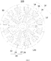
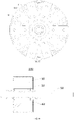
- FIG. 1 is a schematic cross-sectional view of an embodiment of a motor provided by the present application along the axis perpendicular to the axial direction
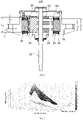
- FIG. 2 is a schematic cross-sectional view of the motor shown in FIG. 1 along the axial direction.
- the motor 100 includes a rotor and a stator.
- the rotor includes a rotor iron core 10, a plurality of magnets 30, an overmold 40 and a rotor shaft 50, wherein a plurality of magnet 30 are embedded on the rotor iron core 10, and the overmold 40 is covered on the rotor iron core 10, so that the rotor iron core 10 and the plurality of magnets 30 are combined to form a rotor, and the rotor shaft 50 is connected to the rotor iron core 10.
- the shaft hole 120 on the rotor iron core 10 is assembled to output power through the rotor shaft 50.
- the stator is wound around the outer periphery of the rotor, and includes a stator iron core 20, a winding 26, a bobbin 60 and a plastic package 70.
- the winding 26 is wound on the stator iron core 20, and the winding 26 generates an alternating magnetic field when being powered on, thereby driving the rotor to rotate.
- the bobbin 60 covers the inner surface of the stator slot 24 on the stator iron core 20 to isolate the winding 26.
- the plastic package 70 is wrapped on the stator iron core 20 to encapsulate the stator iron core 20, the winding 26 and the bobbin 60, so as to prevent impurities and the like from entering the stator iron core 20.
- the rotor iron core 10 specifically includes a collar portion 12 and a plurality of sector-shaped portions 14 surrounding the collar portion 12 and arranged at intervals, and an accommodating groove 16 is formed between two adjacent sector-shaped portions 14, so that a plurality of accommodating grooves 16 are formed at intervals along the circumferential direction of the collar portion 12 on the rotor iron core 10.
- Each accommodating groove 16 is provided with a magnet 30.
- the shaft hole 120 is provided on the collar portion 12, and the rotor shaft 50 is assembled with the shaft hole 120, such as interference fit or gap fit.
- the N pole and the S pole of the magnet 30 are respectively attached to the side surfaces of the two adjacent sector-shaped portions 14, and the opposite surfaces on the adjacent magnet 30 have the same polarity, that is, the same S pole or N pole. Therefore, the sector-shaped portions 14 sandwiched by the adjacent two magnets 30 exhibit S or N magnetic polarity correspondingly, while the adjacent two sector-shaped portions 14 exhibit opposite magnetic polarities.
- the rotor iron core 10 includes an even number of sector-shaped portions 14, and the even number of sector-shaped portions 14 alternately exhibit opposite magnetic polarities of S and N poles in turn in the circumferential direction, and form a closed magnetic circuit.
- the plurality of accommodating grooves 16 are uniformly distributed along the circumferential direction of the collar portion 12.
- the magnet 30 is, for example, a ferrite-based sintered magnet, a neodymium magnet, or the like.
- the magnet 30 has a cuboid structure, and the magnet 30 is arranged in the accommodating groove 16 and penetrates the rotor iron core 10 along the axial direction of the rotor iron core 10.
- the magnet 30 may also be a structure such as a trapezoid, which is not limited in this application.
- the overmold 40 is a resin material and is formed on the rotor iron core10 and the magnet 30 by injection molding. The overmold 40 is further filled in the gap between the magnet 30 and the rotor iron core 10.
- the stator iron core 20 includes a plurality of stator units 22 enclosed in a ring shape, and each stator unit 22 is provided with a winding 26.
- Stator slots 24 are formed between adjacent stator units 22, and the windings 26 are wound on the corresponding stator units 22 and arranged in the stator slots 24.
- the winding 26 is a three-phase winding, and the windings of each phase are wound on the stator unit 22 at intervals in turn, and the alternating magnetic field is generated by sequentially energizing the windings of each phase according to a rule.
- the present application provides an embodiment for optimizing the motor from the perspective of the number of stator slots and the number of rotor poles of the motor 100.
- the pole slot factors of the motor 100 are defined as the absolute value of the difference between the number of stator units 22 and the number of sector-shaped portions 14, and the P-S coefficient k P-S of the motor 100 is t a sum of a reciprocal of the pole slot factor and a reciprocal of a positive adjacent natural number of pole slot factor, and the P-S coefficient k P-S is limited in the range of 0.4 to 0.5 and 0.8 to 1, the range includes the endpoint values 0.4, 0.5, 0.8 and 1, and the number of slots per pole and phase of motor 100 is limited to be greater than or equal to 0.35 and less than or equal to 0.5.
- the number of slots per pole and phase is the ratio of the number of slots to the product of the number of poles multiplied by the number of phases.
- , P-S coefficient k P-S [s+(s +1)]/[s ⁇ (s+1)], the expression for the number of slots per pole and phase is: z/(2p ⁇ 3).
- the number of magnet 30 when the number of rotor poles is relatively small, the number of magnet 30 is also small, and the magnetic flux on the rotor is low, so it passes between the rotor and the stator.
- the magnetic flux involved in the electromechanical energy conversion of the air gap is also lower, and the power density of the motor 100 is also lower.
- the radial dimension of the magnet 30 needs to be relatively increased to increase the magnetic flux on the rotor, and the radial dimension of the rotor iron core 10 will also increase, so the cost of the motor 100 will increase.
- the number of poles 2p and the number of slots z have a great impact on the efficiency, performance and cost of the motor 100.
- the number of poles 2p and the number of slots z also have a great impact on the electromagnetic vibration amplitude of the motor 100.
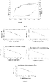
- FIG. 3 is a schematic diagram of the efficiency of the motor 100 as a function of the number of poles 2p, the number of slots z
- FIG. 4 is a schematic diagram of the motor efficiency as a function of the P-S coefficient of the motor k P-S
- FIG. 5 is a schematic diagram of a percentage of electromagnetic vibration amplitude as a function of the P-S coefficient of the motor k P-S .
- the efficiency of motor 100 first increases and then decreases with the increase of the number of slots z, and the efficiency of motor 100 also increases first and then decreases with the increase of the number of poles 2p.
- the number 2p is not conducive to maximizing the efficiency of the motor 100, and the peak efficiency of the motor 100 occurs in the range of the slot number z from 5 to 15 and the pole number 2p from 0 to 20.
- FIG. 4 and FIG. 5 are drawn on the premise that the number of slots per pole per phase is greater than or equal to 0.35 and less than or equal to 0.5. Specifically, the higher the motor efficiency and the lower the electromagnetic vibration effect of the motor, the better the performance of the motor.
- the motor efficiency forms two peaks with the increase of the P-S coefficient of the motor k P-S , and it can be concluded from FIG. 4 that the local peak of the motor efficiency appears when the P-S coefficient of the motor k P-S is between 0.4 and 0.5 and 0.8 and 1 within the segment.
- FIG. 4 the motor efficiency forms two peaks with the increase of the P-S coefficient of the motor k P-S , and it can be concluded from FIG. 4 that the local peak of the motor efficiency appears when the P-S coefficient of the motor k P-S is between 0.4 and 0.5 and 0.8 and 1 within the segment.
- the percentage of electromagnetic vibration amplitude appears two valleys with the increase of the P-S coefficient of the motor k P-S , and it can be concluded from FIG. 5 that the local trough value of the percentage of electromagnetic vibration amplitude appears when the P-S coefficient of the motor k P-S is 0.4 to 0.5 and within the range between 0.8 and 1.
- this application selects two ranges of P-S coefficient k P-S greater than or equal to 0.4 and less than or equal to 0.5 or greater than or equal to 0.8 and less than or equal to 1.
- the number of slots is greater than or equal to 0.35 and less than or equal to 0.5.
- the above motor efficiency and electromagnetic vibration amplitude percentage are greatly improved compared to existing products.
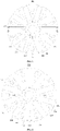
- the present application in order to improve the efficiency of the motor 100 and reduce the vibration and noise of the motor, the present application also provides an optimization method for the motor 100 from the perspective of the air gap between the stator and the rotor of the motor 100 and the outer diameter of the rotor. implementation.
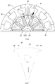
- the design of the uneven air gap is adopted between the stator iron core 20 and the rotor iron core 10, and the uneven air gap changes periodically along the outer circumference of the rotor iron core 10.
- an uneven air gap is formed between each sector-shaped portion 14 and the stator teeth 24, so the uneven air gap between the stator iron core 20 and the rotor iron core 10 changes periodically along the outer circumference of the rotor iron core 10.
- the radial distance between the outer peripheral side of the rotor iron core 10 and the inner peripheral side of the stator iron core 20 is also uneven, and this The unevenness of the radial spacing also changes periodically along the outer circumference of the rotor iron core 10.
- the size of the air gap between any part of the stator unit 22 and the sector-shaped portion 14 may increase first and then decrease with the rotation of the rotor iron core 10 repeatedly, or may also decrease first and then increase with the rotation of the rotor iron core 10 repeatedly.
- the collar portion 12 has a shaft hole 120
- the outer edges of the sector-shaped portion 14 include a first arc segment 141 concentric with the shaft hole 120 and respectively connected to the two second arc segments 143 at both ends of the first arc segment 141, wherein the second arc segments 143 and the first arc segments 141 are not concentric. That is, the second arc segments 143 are not concentric with the shaft hole 120, but are eccentric relative to the shaft hole 120.
- the rotor and the stator are arranged concentrically, so that an even air gap can be formed between the second arc segments 143 on both sides and the stator teeth 24.
- the air gap between the second arc segments 143 and the stator unit 22 is gradually increased or gradually decreased, so as to reduce the harmonic ratio of the back EMF of the motor 100 and improve the efficiency of the motor.
- the radial air gap between the first arc segment 141 and the stator unit 22 constitutes the minimum air gap ⁇ 1 of the uneven air gap.
- the outer edge of the sector-shaped portion 14 further includes two straight line segments 145 respectively connected to the two second arc segments 143.
- the straight line segments 145 are arranged at the outer end of the outer contour of the sector-shaped portion 14, so when the rotor iron core 10 is plastic-sealed, part of the plastic at the accommodating groove 16 can flow to the arc surface of the outer contour of the rotor iron core 10 through the straight line segments 145, so that the rotor iron core 10 can better prevent flashing, that is, to prevent the plastic from protruding out of the second arc segments 143, thereby avoiding friction between the rotor and the stator.
- the outline of the inner peripheral surface of the stator iron core 20 is a regular circular inner surface
- the outline of the outer peripheral surface of the rotor iron core 10 is an irregular circular outer surface, so that an uneven air is formed between the rotor iron core 10 and the stator iron core 20.
- the contour of the inner peripheral surface of the stator iron core 20 and the contour of the outer peripheral surface of the rotor iron core 10 are both irregular circular surfaces, and an uneven air gap may also be formed between the rotor iron core 10 and the stator iron core 20.
- the uneven air gap is optimized from the minimum air gap and the ratio of the minimum air gap to the maximum air gap, so that the uneven air gap can improve the efficiency of the motor 100 and reduce the vibration and noise of the motor 100.
- the size of the air gap 8 along the radial direction and the side area of the rotor determine the magnetic field distribution and the magnetic flux conversion efficiency between the rotor and the stator.
- FIG. 8 is a schematic diagram illustrating the motor efficiency as a function of the air gap of the motor and the outer diameter of the rotor.
- the air gap 8 corresponds to the outer diameter D one-to-one
- the present application takes the minimum air gap ⁇ 1 of the even air gap and the corresponding outer diameter D r of the rotor iron core 10 as an example for description.
- the motor efficiency decreases with the increase of the outer diameter D; when the air gap ⁇ is 0.35 mm, the motor efficiency increases first and then decreases with the increase of the outer diameter D; when the air gap ⁇ is 0.4 mm, 0.45 mm and 0.5 mm, the motor efficiency increases with the increase of the outer diameter D.
- the outer diameter D is 45mm, the motor efficiency decreases with the increase of the air gap ⁇ ; when the outer diameter D is 47mm, 49mm, 51mm, 53mm and 55mm, the motor efficiency first increases and then decreases with the increase of the air gap ⁇ .
- the reason for the first increase in the motor efficiency is that when the outer diameter D of the rotor iron core 10 is large.
- the rotor power density is high, and as the air gap increases, the air gap reluctance increases, the corresponding magnetic flux on the rotor decreases, and the iron loss decreases.
- the magnetic load on the motor is higher than the electrical load, and in the process of increasing the air gap ⁇ , the magnetic load gradually decreases, while the electrical load gradually increases until an equilibrium point is reached, the efficiency of the corresponding motor reaches the maximum, after which the magnetic load is smaller than the electrical load, and the motor efficiency gradually decreases.
- the motor efficiency shows a trend of first increasing and then decreasing.
- the side area of the rotor decreases, and the air-gap reluctance increases.
- the magnetic load on the motor in this interval is higher than the electrical load, and in the process of reducing the outer diameter of the rotor, the magnetic load increases. It gradually decreases, while the electrical load gradually increases until the two reach a balance, which corresponds to the maximum motor efficiency. After that, the magnetic load is smaller than the electrical load, and the motor efficiency gradually decreases.
- the size of the air gap ⁇ and the rotor outer diameter D are arranged to satisfy the following condition: the quotient obtained by dividing the product of the minimum air gap ⁇ 1 of the even air gap and the number 2p of the sector-shaped portion 14 by the corresponding circumference of the rotor iron core 10 is greater than or equal to 0.01 and less than or equal to 0.05. Under this condition, the motor efficiency can be optimized.
- ⁇ D r is the circumference of the rotor iron core 10 corresponding to the minimum air gap ⁇ 1
- D r is the outer diameter of the rotor iron core 10 corresponding to the minimum air gap ⁇ 1 .
- the air gap width ⁇ 1 is selected as 0.35mm and the outer diameter D r of rotor iron core10 is 50.2mm
- the air gap aspect ratio is 0.022.
- the above design method achieves the purpose of improving the efficiency and power density of the motor 100 by limiting the range of the air gap aspect ratio.
- the ratio of the minimum air gap to the maximum air gap of the uneven air gap is further optimized to reduce the vibration noise of the motor 100.
- the harmonic content of the motor 100 is relatively high, and the interaction of the harmonic magnetic fields of the stator and the rotor during the operation of the motor 100 is likely to generate ripple torque and radial force waves. In turn, torque fluctuation and radial vibration are generated, which brings noise problems to the operation of the motor 100.
- the harmonic magnetic field is improved, thereby avoiding or reducing the vibration and noise of the motor 100.
- the air gap magnetic resistance should be sinusoidally distributed as much as possible, so that the content of the harmonic components contained in it should be reduced as much as possible. It is also necessary to optimize the design of the outer contour of the rotor iron core 10.
- the present application further optimizes the uneven air gap under the premise of optimizing the aspect ratio of the air gap, so as to minimize the harmonic content of the motor magnetic field.
- the minimum air gap between stator iron core 20 and rotor iron core 10 is ⁇ 1
- the maximum air gap is ⁇ 2
- the maximum air gap ⁇ 2 and the minimum air gap ⁇ 1 and their transition process are optimized.
- the specific design process should satisfy the balance between the motor efficiency and the magnetic field distortion rate, and the magnetic field distortion rate and performance of the motor should be optimally analyzed to obtain the variation trend of the motor efficiency and distortion rate with the ratio k of the maximum air gap and the minimum air gap, as shown in FIG. 9 .
- the motor efficiency drops significantly.
- the provided magnetic flux area decreases, thereby reducing the power density of the rotor, and at the same time, the Carter coefficient of the air gap increases, and the performance and efficiency of the motor 100 decrease in the overall trend.
- the maximum air gap ⁇ 2 is too narrow, and the motor efficiency is higher. This is because the magnet 30 has a larger radial dimension and length, which can provide a larger magnetic energy product.
- the Carter coefficient of the air gap is small, and the motor efficiency increases, but due to the gap between the maximum air gap ⁇ 2 and the minimum air gap ⁇ 1 is small, and the sinusoidal fluctuation of the air gap reluctance has little effect on the overall magnetic circuit, so the magnetic field distortion rate is high, and the goal of optimizing the air gap magnetic field cannot be achieved.
- the motor efficiency can be guaranteed to be high.
- its magnetic field distortion rate is low.
- the minimum air gap ⁇ 1 is designed to be 0.3mm, and it is reasonable to determine the maximum air gap ⁇ 2 to be between 0.37-0.6.
- the air gap ratio coefficient k is selected to be 0.65, and the maximum air gap ⁇ 2 is determined to be 0.46 mm.
- the present application in order to improve the efficiency of the motor 100 and reduce the cost of the motor, also provides an optimization method for the motor 100 from the perspective of the rotor outer diameter D of the motor 100 and the radial length l PM of the magnet 30 implementation.
- the motor efficiency decreases with the increase of the radial length l PM.
- the magnetic load of the motor is more than the electrical load, and then the magnetic load is related to the electrical load.
- the gap between the loads gradually increases, the degree of magnetic supersaturation of the motor is high, the iron loss gradually increases, and the motor efficiency gradually decreases.
- the motor efficiency increases first and then decreases with the increase of the radial length l PM.
- the magnetic load of the motor increases with the increase of the radial length l PM increase, and the electrical load gradually decreases until the two reach a balance, and the motor efficiency also reaches a local peak. After that, the magnetic load exceeds the electrical load, and the motor efficiency gradually decreases.
- the motor efficiency increases with the increase of the radial length l PM.
- the magnetic load of the motor increases with the increase of the radial length l PM , and the difference between the magnetic load and the electrical load increases. The gap is gradually narrowing, and the motor efficiency is gradually improving.
- the radial length l PM and the rotor outer diameter D r of the magnet30 with the best efficiency should meet the following conditions: the quotient obtained by dividing the circumference of the largest circumference formed by the outer circumference of the rotor iron core10 by the number of sector-shaped portions 14 and the radial length l PM of the magnet 30 of the rotor iron core 10 is greater than or equal to 1 and less than or equal to 1.4.
- the circumference determined by the outer diameter D r corresponding to the minimum air gap ⁇ 1 is the maximum circumference, that is, 1 ⁇ ( ⁇ D r )/((2p l PM ) ⁇ 1.4).
- the outer diameter D r of the rotor is selected to be 50 mm, and a suitable size range of the radial length l PM of the magnet 30 can be obtained, and a regular value can be selected within this range.
- the present application also provides an implementation manner for optimizing the motor 100 from the perspective of the axial dimensions of the stator iron core 20 , the rotor iron core 10 and the magnet 30 of the motor 100.
- the main parts of the materials that are beneficial to motor performance are the cost of copper (winding 26), the cost of steel/iron (stator iron core 20 and rotor iron core 10), and the cost of magnet (magnet30).
- magnet 30 is combined with rotor iron core 10 and then magnetized, magnet 30 cannot reach saturation. Therefore, if you want to maintain better efficiency performance of the motor, you must increase the cost of copper, and copper is a precious metal, so increase the amount of copper used will increase the cost of motor 100. If the motor performance is improved by increasing the amount of magnet 30, there will be a certain marginal effect.
- the amount of magnet 30 exceeds a certain threshold, the improvement of motor performance is not obvious, but the cost of the motor increases significantly. If the level of magnet 30 is increased, for example, the original use of 6 series is changed to 9 series, then the price of magnet 30 will double, the cost of the motor 100 will be higher. For motor 100, the price of steel/iron material is lower than that of copper and magnet 30. Therefore, increasing the length of the rotor iron core10 along the axial direction to improve the motor performance is relatively preferred, that is, the motor 100 solution provided in the present application can improve the performance of motor 100 with relatively small cost.
- the axial length L3 of the magnet 30 is set to be greater than or equal to the axial length L1 of the rotor iron core 10.
- the collar portion 12 has a shaft hole 120, and the axial direction is the axis direction of the shaft hole 120.
- the two end surfaces of the magnet 30 can be set to be aligned with the two end surfaces of the rotor iron core 10, or one end surface of the magnet 30 can be aligned with one end surface of the rotor iron core 10, and the other end surface of the magnet 30 protrudes from the other end surface of the rotor iron core 10.
- the two end surfaces of the magnet 30 respectively protrude from the two end surfaces of the rotor iron core 10, and the protruding lengths of the two end surfaces of the magnet 30 relative to the two end surfaces of the rotor iron core 10 may be equal or different.
- the above setting method can generate a relatively saturated magnetic field in the rotor iron core 10, improve the magnetic density on the rotor iron core 10, and then improve the power density of the motor 100, so as to improve the performance efficiency of the motor 100.
- the length L 1 of the rotor iron core 10 in the axial direction of the shaft hole 120 can also be set to be greater than or equal to the length L 2 of the stator iron core 20 in the axial direction.
- the length L 1 of the rotor iron core 10 in the axial direction is equal to the length L 2 of the stator iron core 20 in the axial direction, and the two end surfaces of the rotor iron core 10 are aligned with the two end surfaces of the stator iron core 20, so that the side surfaces of the rotor iron core 10 are at least aligned with the inner side of stator iron core 20 to facilitate magnetic field distribution and flux conversion in the air gap interval.
- the length L 1 of the rotor iron core 10 in the axial direction is greater than the length L 2 of the stator iron core 20 in the axial direction, and the first end surface of the rotor iron core 10 is relatively protruding or aligned with the first end of the stator iron core 20 in the axial direction. surface, the second end surface of the rotor iron core10 protrudes relatively from the second end surface of the stator iron core 20.
- the protruding end magnetic field of the rotor iron core 10 can be used to make up for the performance loss caused by the unsaturated magnetization of the magnet 30, which improve the performance of motor 100 with small cost.
- the ratio of the length L 1 of the rotor iron core 10 to the length L 2 of the stator iron core 20 is greater than or equal to 1.0 and less than or equal to 1.25, and this size range will compensate for the magnetization unsaturated effect of the magnet 30 with a higher axial end magnetization effect.
- the resulting performance loss is used to increase the power density of the motor 100 to improve the efficiency performance of the motor 100.
- the first end surface of the rotor iron core 10 is aligned with the first end surface of the stator iron core 20, the second end surface of the rotor iron core 10 protrudes from the second end surface of the stator iron core 20, and the two ends of the magnet 30 protrude in the axial direction relative to the rotor iron core 10, and then use the protruding ends of the magnet 30 from the rotor iron core 10 to generate a magnetic field entering the rotor iron core 10 due to the end effect, and use the end of the magnet 30 protruding from the rotor iron core 10 to generate magnetic field contacted with the stator iron core 10 to improve the efficiency of the motor 100.
- the protruding lengths of both ends of the magnet 30 relative to the two ends of the rotor iron core 10 are the same, so that the magnetic densities generated by the magnet 30 in the rotor iron core 10 are the same, and the performance of the rotor iron core 10 is more balanced, which is favorable to improve the motor 100 performance.
- the quotient obtained by dividing the difference between the length L 3 of the magnet 30 in the axial direction and the length L 1 of the rotor iron core 10 by the length L 2 of the stator iron core 20 is greater than or equal to 0.15 and less than or equal to 0.45.
- the magnetic concentration effect produces a higher end magnetic field to improve the performance of the motor 100.
- the two end surfaces of the magnet 30 can also protrude asymmetrically in the axial direction relative to the two end faces of the stator iron core 20, that is, the protruding lengths of the magnet 30 from the two end surfaces of the stator iron core 20 are different, wherein the magnet 30 protrudes from the end surface of the stator iron core 20.
- the end with the longer protruding length is used to install the sensor to monitor the running state of the motor 100.
- the end of the magnet 30 protruding from the end surface of the stator iron core 20 with the shorter length can produce a higher end magnetic field with the magnetization effect at the end to improve the performance of the motor 100.
- the first length L 4 of the magnet 30 protruding from the first end surface of the stator iron core 20 is greater than or equal to 2 mm and less than or equal to 6 mm
- the second length L 5 of the magnet 30 protruding from the second end surface of the stator iron core 20 is greater than or equal to 4 mm and less than or equal to 8 mm.
- the size range of the first length L 4 can not only facilitate the installation of sensors to detect the running state of the motor 100, but also cooperate with the size range of the second length L 5 to improve the performance of the motor 100 with a higher end magnetic field generated by the end magnetic concentration effect.
- the present application also provides an optimization method for the rotor from the perspective of the rotor, so as to reduce the influence on the motor performance, noise and reliability caused by foreign objects such as iron filings in the air gap.
- a debris adsorption groove 41 is provided on the overmold 40.
- the overmold 40 covers the magnet 30 and is formed on the two end surfaces and the side of the rotor iron core 10.
- the part of the overmold 40 formed on the side of the rotor iron core 20 is provided with a debris adsorption groove 41.
- the debris adsorption groove 41 is used to absorb the rotor during the operation.
- the adsorbed tiny foreign objects reduce the risk of friction between the rotor and the stator when the rotor is rotated due to foreign objects such as metal chips being adsorbed on the surface of the rotor, which is beneficial to improve the performance of the motor.
- the overmold 40 specifically includes an end surface covering portion 42 and a side filling portion 44.
- the end surface covering portion 42 covers the magnet 30 on the end face of the rotor iron core 10 and exposes the collar portion 12 and the sector-shaped portion 14 on the end surface of the rotor iron core 10. That is, the end surface covering portion 42 covers at least the magnet 30 on the end surface of the rotor iron core 10 and exposes at least part of the collar portion12 and part of the sector-shaped portion 14.
- the end surface covering portion 42 covers and wraps the protruding portion of the magnet 30 from the end surface of the rotor iron core 10, and plays an axial fixing role for the magnet 30. Further, positioning holes may be provided on two opposite sides of the magnet 30 for positioning the axial length of the end surface of the magnet 30 protruding from the rotor iron core 10.
- At least one positioning hole 424 is formed on the end surface covering portion 42 corresponding to each magnet 30.
- two positioning holes 424 are formed on the end surface covering portion 42 corresponding to each magnet 30.
- the positioning hole 424 is used for positioning the magnet 30, and can reduce the material used for the end surface covering portion 42, and further, fill the positioning hole 424 to perform dynamic balance correction on the rotor.
- the end surface covering portion 42 includes a collar covering sub-portion 420 and a plurality of magnet covering sub-portion 422, the plurality of magnet covering sub-portion 422 are radially connected to the collar covering sub-portion 420, the collar covering sub-portion 420 covers at least part of the collar portion 12, and each magnet covering sub-portion 422 covers at least a magnet 30 correspondingly, a space is formed between the magnet covering sub-portion 422 and the sector-shaped portion 14 is exposed.
- a balance hole 146 may be provided on a portion of the sector-shaped portion 14 exposed from the end surface covering portion 42, and the balance hole 146 penetrates the sector-shaped portion 14.
- the arrangement of the balance hole 146 can not only reduce the weight of the rotor iron core 10, but also can dissipate heat to the rotor iron core 10, and can also perform dynamic balance correction of the rotor by filling the balance hole 146 with material to increase the weight.
- each sector-shaped portion 14 is provided with a balance hole 146.
- the balance hole 146 may be provided only on part of the sector-shaped portion 14.
- a retaining ring 426 may also be arranged between two adjacent magnet covering sub-portions 422, the retaining ring 326 is arranged at the outer periphery of the sector-shaped portion 14, and thus the balance hole 146 is arranged an area enclosed by the retaining ring 426 , the magnet covering sub-portion 422 and the collar covering sub-portion 420, the retaining ring 426 can prevent the filler from overflowing to the side of the rotor iron core 10 when filling the balance hole 146, and can also increase the reliability of the filler being fixed on the rotor iron core 10, and prevent the centrifugal force from causing throwing off of the filler when the rotor rotates at high speed. It is also easy to handle the packing quickly and reduce the risk of quality problems.
- the side filling portion 44 is connected to the end surface covering portion 42, covers the magnet 30 on the side of the rotor iron core 10, and exposes the sector-shaped portion 14 on the side of the rotor iron core 10; the debris adsorption groove 41 is formed in the side filling portion 44.
- the debris adsorption groove 41 is formed in the side filling portion 44 extending along the axial direction of the rotor iron core 10.
- the debris adsorption groove 41 is arranged in the side filling portion 44 with an angle relative to the axial direction.
- a plurality of debris adsorption grooves 41 are arranged in the side filling portion 44, and a debris adsorption groove 41 is formed on the side filling portion 44 corresponding to each magnet 30.
- a debris adsorption groove 41 is formed on the side filling portion 44 corresponding to every two magnets 30.
- a plurality of debris adsorption grooves 41 are formed on the side filling portion 44 corresponding to each magnet 30, and the plurality of debris adsorption grooves 41 are distributed along the axial direction.
- the side filling portion 44 is connected to the side surface of the rotor iron core 10 in alignment, that is, the connection is smoothly transitioned, so as to reduce the wind resistance suffered by the rotor when it rotates.
- the sector-shaped portion 14 protrudes away from the outer edge of the collar portion 12 toward the accommodating groove 16 to form a stopper 140, and the magnet 30 abuts against the stopper 140; the two opposite stoppers 140 between two adjacent sector-shaped portions 14 form a gap 142, and the existence of the gap 142 is beneficial to greatly reduce the magnetic flux leakage of the rotor iron core 10.
- the side filling portion 44 is filled in the gap 142, and the side filling portion 44 is connected to the side surfaces of the rotor iron core 10 in alignment, and the side filling portion 44 is connected to the magnet covering sub-portion 422 on both end surfaces of the rotor iron core 10.
- the magnet 30 is provided with a debris adsorption groove 32.
- the main difference is that one side of the magnet 30 is exposed from the side of the rotor iron core 10 and the debris adsorption grooves 32 are arranged thereon, and then a plurality of debris adsorption grooves 32 are exposed from the side of the rotor iron core 10.
- the debris adsorption groove 32 is exposed from the gap 142 formed by the two stoppers 140, and foreign objects such as iron filings can enter the debris adsorption groove 32 from the gap 142 and be magnetically absorbed by the debris adsorption groove 32, so as to avoid the foreign matter such as iron filings from affecting the motor's performance, noise and reliability.
- the overmold 40 is not filled in the gap 142, that is, the overmold 40 does not include the above-mentioned side filling portion 44, the overmold 40 includes the end surface covering portion 42, and the debris adsorption groove 32 is exposed from the gap 142.
- the overmold 40 is also filled in part of the gap 142, so that the overmold 40 can also be formed on the side of the rotor iron core 10, and the debris adsorption groove 32 is exposed from the gap 142 that is not filled with the overmold 40.
- the debris adsorption groove 32 is formed on the magnet 30 along the axial direction of the rotor iron core 22, that is, a debris adsorption groove 32 is formed on the magnet 30 along the axial direction.
- a plurality of debris adsorption grooves 32 are distributed along the side of one magnet 30 in the axial direction.
- a debris adsorption groove 32 is formed on one of the adjacent two, three, etc. of magnets 30.
- the simulation analysis shows that the magnet part of the magnet 30 exposed in the gap 142 has the lowest magnetic induction intensity, and the magnetic induction intensity of the part of the magnet that is covered by the stopper 140 is the highest on both sides adjacent to the lowest magnetic induction intensity.
- a debris adsorption groove 32 is opened at the low magnetic field of the magnet 30, and the debris adsorption groove 32 is exposed from the gap 142 to the rotor.
- the side of the iron core 10 to attract foreign objects such as iron filings into it, so as to avoid the impact of iron filings on motor performance, noise and reliability.
- the rotor iron core 10 is provided with the debris adsorption groove 144.
- the main difference is that the side of the sector-shaped portion 14 away from the collar portion 12 is provided with a debris adsorption groove 144.
- the debris groove adsorption 144 may be provided anywhere on the sidewall of the sector-shaped portion 14 away from the collar portion 12.
- a side of the stopper 140 away from the collar portion 12 is provided with a debris adsorption groove 144.
- the magnetic flux passing through the stopper 140 is greatly greater than the magnetic flux passing through the same size cross-sectional area of the sector-shaped portion 14, even the stopper 140 is in a state of magnetic saturation, that is, the magnetic induction intensity at the stopper 140 is high.
- the electromagnetic simulation analysis of the rotor iron core10 also shows that the magnetic induction intensity at the connection of the stopper 140 is high, so it can absorb the iron filings and other small foreign objects outside the rotor iron core10. and choose to arrange debris adsorption groove144 on stopper 140.
- the magnetic field distribution on the rotor iron core 10 is fully and effectively used, and the debris adsorption groove 144 is arranged on the stopper 140 to absorb impurities such as iron filings, and at the same time, the performance of the rotor iron core 10 is not adversely affected, and due to the location of the debris adsorption groove 144, the magnetic field strength at the rotor iron core 10 is stronger than that at other positions on the side of the rotor iron core 10, so the debris adsorption groove 144 can effectively adsorb tiny foreign objects such as iron filings.
- the two stoppers 140 with the gap 142 can also be connected into one body, that is, the outer peripheries of the adjacent sector-shaped portions 14 are connected to each other, so that the overmold 40 only includes the end surface covering portion 42 , and the debris adsorption groove 144 can also be arranged in the sector-shaped portion 14 away from any position on the side wall of the collar portion 12.
- the above debris adsorption grooves (41, 32, 144) can exist at the same time, one of the three, or two of the three, which can effectively prevent foreign objects such as iron filings from affecting motor's performance, noise and reliability.
- the present application in order to reduce the shaft voltage on the rotor shaft 50, the present application also provides an embodiment optimized for the rotor from the perspective of the rotor shaft 50 and the shaft hole 120 to electrostatically isolate the rotor iron core 10 and the rotor shaft 50.
- the rotor shaft 50 and shaft hole 120 may be fitted with interference.
- the diameter of the shaft hole 120 is larger than the diameter of the rotor shaft 50 , the rotor shaft 50 and the shaft hole 120 are coaxially arranged to keep the rotor in dynamic balance as a whole, and the rotor shaft 50 and the rotor iron core 10 are combined into one piece through the overmold 40.
- the overmold 40 is filled between the rotor shaft 50 and the inner wall of the shaft hole 120 to isolate and insulate the rotor iron core 10 and the rotor shaft 50, and to fix the rotor shaft 50 and the rotor iron core 10, thereby changing the electrostatic capacity of the rotor side, so that the electrostatic capacity of one side of the rotor and the electrostatic capacity of the matched stator side are easily balanced, thereby reducing the shaft voltage on the rotor shaft 50 and improving the electrical corrosion of the bearing.
- the rotor shaft 50 includes a shaft body 52 and a shaft groove 54 provided on the shaft body 52, and the outer diameter of the shaft groove 54 is smaller than the outer diameter of the shaft body 52.
- the portion corresponding to the shaft groove 54 is arranged in the shaft hole 120, and the overmold 40 is filled between the shaft groove 54 and the inner wall of the shaft hole 120.
- the shaft body 52 may further be provided with a plurality of shaft grooves 54, the plurality of shaft grooves 54 are distributed on the shaft body 52 at intervals along the axial direction, and the plurality of shaft grooves 54 are all arranged in the shaft hole 120, so that the overmold 40 is filled in the shaft hole 120. Between the plurality of shaft grooves 54 and the inner side wall of the shaft hole 120, the rotational torque between the rotor shaft 50 and the rotor iron core 10 can be increased to prevent the rotor shaft 50 and the rotor iron core 10 from loosening.
- the surface of the shaft groove 54 is protruded or recessed to form a disengagement prevention portion 540 for increasing the rotational torque between the rotor shaft 50 and the rotor iron core 10, preventing falling off between the rotor shaft 50 and the iron core10 during use.
- a groove-shaped disengagement prevention portion 540 is formed on the surface of the shaft groove 54, or a boss-shaped disengagement prevention portion 540 is formed on the surface of the shaft groove 54, and the combination of the overmold 40 and the disengagement prevention portion 540 can increase the rotation torque between the rotor shaft 50 and the rotor iron core 10.
- the overmold 40 is made of elastic material, so as to absorb and buffer the tangential moment fluctuation of the rotor iron core 10 and the rotor shaft 50 during the rotation process, so as to reduce abnormal vibration transmitted through the rotor shaft 50 and reduce vibration noise.
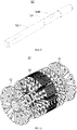
- the present application in order to reduce the magnetic flux leakage of the motor 100, the present application also proposes an implementation method for optimizing the rotor iron core 10 from the perspective of the rotor iron core structure.
- the rotor iron core 10 includes a first rotor punching group 11, a second rotor punching group 13 and a third rotor punching group 15 which are stacked in sequence.
- both the first rotor punching group 11 and the third rotor punching group 15 are formed by stacking a plurality of first rotor punching plates 110, and the first rotor punching plate 110 includes a first ring plate 112 and a plurality of first sector-shaped plates 113 arranged at intervals around the first ring plate 112, a plurality of first sector-shaped plates 113 in each first rotor punching plate 110 are connected to the first ring plate 112.
- the second rotor punching group 13 is formed by stacking a plurality of second rotor punching plates 130.
- the second rotor punching plate 130 includes a second ring plate 132 and a plurality of second sector-shaped plates 133 arranged at intervals around the second ring plate 132.
- the second sector-shaped plate133 and the second ring plate132 are connected and disconnected alternately.
- the first ring plate 112 and the second ring plate 132 are stacked to form the collar portion 12, and the first sector-shaped plate 113 and the second sector-shaped plate 132 are stacked to form the sector-shaped portion 14.
- connection and disconnection of the second sector-shaped plate 133 and the second ring plate132 in the second rotor punching plate130 are staggered, so part of the second sector-shaped plate 133 is not connected to the second ring plate 132, that is, part of the second sector-shaped plate 133 is independent of the second ring plate 132.
- second sector-shaped plates 133 It is fixed by other second sector-shaped plates 133 stacked adjacent to each other, that is, there is an air gap magnetic resistance between the second sector-shaped plate 133 and the second ring plate 132, so that magnetic leakage can be reduced; the second sector-shaped plate 133 is connected to the second ring plate 132, so that the overall strength of the second rotor punching group 13 can be ensured, thereby ensuring the overall strength of the rotor iron core 10.
- the first sector-shaped plate 113 and the second sector-shaped plate 133 are provided with riveting points 116 at the same positions, and two adjacent rotor punches are connected by the riveting points 116, that is, they are arranged adjacent to each other in the axial direction.
- the two first rotor punching plates 110, the two second rotor punching plates 130, and the first rotor punching plates 110 and the second rotor punching plates 130 are all connected by riveting points 116.
- the second sector-shaped plates 133 connected to the second ring plates 132 and the second sector-shaped plates 133 not connected to the second ring plates 132 are stacked.
- the plurality of second rotor punching plates 130 in the second rotor punching group 13 may also have other arrangements.
- half of the second rotor punching plates 130 are stacked on each other, and a second sector-shaped plate 133 is deflected relative to the other half of the second rotor punching plates 130 stacked on each other to form the second rotor punching group 13.
- the second rotor punching group 13 further includes a first rotor punching plate 110, and the first rotor punching plates 110 are distributed among the plurality of second rotor punching plates 130.
- the above is only an example, and the present application does not limit the specific arrangement of the second rotor punching group 13.
- This structural arrangement of the second rotor punching group 13 can reduce the magnetic flux leakage and improve the back EMF coefficient of the rotor iron core 10, thereby improving the performance of the motor 100, ensuring the strength of the rotor iron core 10 itself, and helping to reduce the centrifugal force caused by the rotation during rotation. risk of strength failure.
- a side of the first ring plate 112 facing the first sector-shaped plate 113 is formed with a plurality of spaced first limiting posts 117, and the first limiting post 117 is arranged between two adjacent first sector-shaped plates 113.
- a plurality of second limiting posts 137 are formed on the side of the second ring plate 132 facing the second sector-shaped plate 133, and the second limiting posts 137 are arranged between two adjacent second sector-shaped plates 133.
- the length of the first limiting post 117 in the radial direction of the first ring plate 112 is greater than the length of the second limiting post 137 in the radial direction of the second ring plate 132.
- the number of the first limiting post 117 and the second limiting post 137 are plural, and they are stacked to each other correspondingly.
- the longer first limiting post 117 is used to limit the magnet 30 in the accommodating groove 16, and the shorter second limiting post 137 is guaranteed not to be in contact with the magnet 30 and not to be in contact with the magnet 30.
- balance holes 146 are provided at the same positions of the first sector-shaped plate 113 and the second sector-shaped plate 133, each of the balance holes 146 is correspondingly stacked, and the balance holes 146 penetrate the sector-shaped portion 14.
- a connecting bridge structure is provided between the first sector-shaped plate 113 and the first ring plate 112 and between the second sector-shaped plate 133 and the second ring plate 132. Specifically, the plurality of first sector-shaped plates 113 are connected to the first ring plate 112 through the first connecting bridge 119.
- the second rotor punching plate 13 is provided with a second connecting bridge 135 and a breaking connecting bridge 136 in a staggered manner, wherein a part of the second sector-shaped plate 133 is connected to the second ring plate 132 through the second connecting bridge 135, and another part of the second sector-shaped plate 133 and the second ring plate 132 are arranged at intervals through the breaking connecting bridge 136, the gap between the second sector-shaped plate 133 and the second ring plate 132 arranged at intervals is as the breaking connecting bridge 136.
- the ratio of the width of the first connecting bridge 119, the second connecting bridge 135 and the breaking connecting bridge 136 along the circumferential direction of the rotor iron core 10 to the thickness of the punching plate is 0.8 to 1.5.
- the thickness of the punching plate is the punching plate thickness of the first rotor punching plate 11 and the second rotor punching plate 13, and the widths of the first connecting bridge 119, the second connecting bridge 135 and the breaking connecting bridge 136 are all the same.
- the first connecting bridge119 and the second connecting bridge135 have sufficient strength, and the breaking connecting bridge 136 can better reduce the magnetic flux leakage of the rotor iron core 10.
- the ratio of the length l in the radial direction of the breaking connecting bridge 136 to the width w in the circumferential direction is greater than or equal to a set value.
- the set value is the quotient obtained by dividing the product of the minimum air gap ⁇ 1 of the uneven air gap and the number of sector-shaped portions 2p by 1% of the circumference of the maximum circumference ⁇ D r formed by the outer circumference of the rotor iron core 10.
- the relationship between the length l and the width w is expressed as l/w ⁇ (200p ⁇ 1 )/( ⁇ D r ).
- the length l should be increased and the width w should be reduced as much as possible.
- a smaller length 1 and a larger width w will result in too large magnetic flux leakage of rotor iron core10, and poor performance of the motor.
- too large length l and too small width w will affect the mechanical strength of the rotor iron core 10 and cause safety hazards.
- the length l is greater than or equal to 2.5 mm
- the width w is greater than or equal to 0.3 mm and less than or equal to 1 mm.
- the length l and width w are both the length and width of the first connecting bridge and the second connecting bridge.
- selecting an appropriate length l and width w and making them meet l/w ⁇ (200p ⁇ 1 )/( ⁇ D r ) can reduce the magnetic flux leakage of the rotor iron core 10 as much as possible, improve the power density of the rotor iron core 10, and also ensure the mechanical strength of the rotor iron core 10, improving the power density and efficiency of the motor 100.
- the present application in order to improve the material utilization rate of the motor, also proposes an implementation method for optimizing the stator iron core from the perspective of the structure of the stator iron core.
- the stator unit 22 is generally T-shaped, the stator unit 22 includes a yoke portion 220, a tooth portion 222 and a tooth shoulder 224, the tooth portion 222 is connected between the yoke portion220 and the tooth shoulder 224, and the plurality of yoke portions 220 of the plurality of stator units 22 are connected in sequence, Furthermore, stator slots 24 are formed between adjacent tooth portions 222 to form a plurality of stator slots 24.
- the tooth portions 222 are provided with windings 26, and there is a gap between two adjacent tooth shoulders 224.
- stator iron core 20 includes 12 T-shaped stator units 22, which can be matched with rotors with 8 or 10 poles.
- the outer surface 221 of the yoke portion 220 is flat, forming the polygonal outer surface of the stator iron core 20; the inner surface of the tooth shoulder 224 is arc-shaped, forming the circular inner surface of the stator iron core 20, so that the rotor rotates relatively to the stator iron core 20.
- a plurality of stator units 22 are arranged to engage and connect in sequence and form a ring to form a stator iron core 20, and when the stator units 22 are not combined into a stator iron core 20, each stator unit 22 is independent of each other, thus improving the quality of the materials used to make the stator units 22.
- materials of smaller size can also be used and made into the stator unit 22.
- the outer surface 221 of the yoke portion 220 is arranged to be flat, so that the area occupied by the arc-shaped stator unit on the outer surface of the stator unit 22 relative to the yoke portion is smaller, which further improves the utilization rate of materials, thereby reducing the production cost of stator iron core 20.
- one end of the yoke portion 220 is provided with a protrusion 227, and the other end thereof is provided with a groove 228; a plurality of the yoke portions 220 are sequentially engaged and connected through the protrusion 227 and the groove 228.
- the protrusion 227 is in a semicircular shape
- the groove 228 is in a semicircular groove
- the semi-cylindrical shape is engaged with the semicircular groove to connect two adjacent yoke portions 220.
- the root of the protrusion 227 is provided with a snap groove 2271, and the end of the groove 228 on the yoke portion 220 is provided with a snap 2281 correspondingly.
- the snap 2281 is snap-fitted with the snap groove 2271, thereby the strength of the meshing connection between the stator units 22 can be further enhanced. Referring to FIGS.
- the inner surface 223 of the yoke portion 220 is further flat and parallel to the outer surface 221 of the yoke portion 220, and the tooth portion 222 is perpendicular to the inner surface 223, so that the wires can be attached to the inner surface 223 and start winding from the inner surface 223, so that the wiring on the tooth portion 222 is neat and the full rate of the winding groove is high.
- the inner surface of the yoke portion is a stator iron core with a curved surface, and the maximum slot filling rate of its winding is 65%, while the winding slot filling rate of the stator iron core 20 provided by this application can reach a maximum of 70%, which relatively improves the full rate of the winding slot of the stator iron core 20.
- the inner surface 223 is flat, which can further improve the utilization rate of the material for making the stator unit 22, and the outer surface 221 and the inner surface 223 are both flat, the mold structure for making the stator iron core 20 will become simpler, thereby reducing the mold's cost. The cost further reduces the production cost of stator iron core 20.
- the tooth shoulder 224 is configured as a sloping shoulder, which can effectively improve the magnetic saturation at the connection with the tooth portion 222 compared to the straight shoulder.
- the yoke portion 220 is provided with a first rivet point 225
- the tooth shoulder 224 is provided with a second rivet point 226, and the area of the second rivet point 226 is smaller than that of the first rivet point 225.
- the present application moves the second riveting point 226 down to the tooth shoulder 224 and further reduces the size of the second riveting point 226 relative to the first riveting point 225.
- the size and area can effectively improve the magnetic saturation on the tooth portion 222 and the tooth shoulder 224, and improve the power density of the stator iron core 20.
- first riveting point 225 and the second riveting point 226 are: when the stator iron core 20 is formed by a plurality of stator punching plates are stacked, the first riveting point 225 and the second riveting point 226 are provided.
- the stator iron core 20 is formed by stacking riveted buckles on a plurality of stator punching plates through the first riveting point 225 and the second riveting point 226.
- the motor 100 further includes a bobbin 60, and the bobbin 60 is an insulating bobbin, which is made of, for example, a resin-based insulating material.
- the bobbin 60 covers the inner surface 223 of the yoke portion 220, the inner surface of the tooth portion 222 and the tooth shoulder 224 to isolate the windings 26.
- the motor 100 further includes a plastic package 70 , and the plastic package 70 covers the outer periphery and both end surfaces of the stator iron core 20 to encapsulate the stator iron core 20, the winding 26 and the bobbin 60 to avoid impurities Waiting to enter the stator iron core 20.
- the present application discloses a motor and a household appliance.
- the number of slots per pole and phase of the motor is greater than or equal to 0.35 and less than or equal to 0.5
- the number of slots and poles of the motor is optimized to ensure the motor's harmonic component of the tangential electromagnetic force wave is low, which can reduce the vibration and noise of the motor, and at the same time, it can also make the power density and efficiency of the motor high, and the cost of the motor can be effectively reduced.
- the motor 100 described above can be used as a power source for home appliances or other fields.
Landscapes
- Engineering & Computer Science (AREA)
- Power Engineering (AREA)
- Manufacturing & Machinery (AREA)
- Iron Core Of Rotating Electric Machines (AREA)
- Permanent Magnet Type Synchronous Machine (AREA)
Applications Claiming Priority (2)
| Application Number | Priority Date | Filing Date | Title |
|---|---|---|---|
| CN201910919342.6A CN111384804B (zh) | 2019-09-26 | 2019-09-26 | 电机和家用电器 |
| PCT/CN2019/129350 WO2021056902A1 (fr) | 2019-09-26 | 2019-12-27 | Moteur électrique et appareil électroménager |
Publications (2)
| Publication Number | Publication Date |
|---|---|
| EP4007125A1 true EP4007125A1 (fr) | 2022-06-01 |
| EP4007125A4 EP4007125A4 (fr) | 2022-10-05 |
Family
ID=71218458
Family Applications (1)
| Application Number | Title | Priority Date | Filing Date |
|---|---|---|---|
| EP19946787.9A Pending EP4007125A4 (fr) | 2019-09-26 | 2019-12-27 | Moteur électrique et appareil électroménager |
Country Status (5)
| Country | Link |
|---|---|
| EP (1) | EP4007125A4 (fr) |
| JP (1) | JP7387877B2 (fr) |
| KR (1) | KR20220041193A (fr) |
| CN (4) | CN114598075A (fr) |
| WO (1) | WO2021056902A1 (fr) |
Cited By (1)
| Publication number | Priority date | Publication date | Assignee | Title |
|---|---|---|---|---|
| EP4293881A1 (fr) * | 2022-06-15 | 2023-12-20 | Vorwerk & Co. Interholding GmbH | Moteur électrique, robot de cuisine et procédé de fabrication |
Families Citing this family (3)
| Publication number | Priority date | Publication date | Assignee | Title |
|---|---|---|---|---|
| CN111900811B (zh) * | 2020-08-10 | 2021-11-19 | 广东威灵电机制造有限公司 | 转子、电机及家用电器 |
| CN114039435B (zh) * | 2021-11-04 | 2023-10-03 | 广东美芝精密制造有限公司 | 转子结构、电机结构、压缩机结构和制冷设备 |
| WO2024106841A1 (fr) * | 2022-11-17 | 2024-05-23 | 삼성전자 주식회사 | Moteur |
Family Cites Families (28)
| Publication number | Priority date | Publication date | Assignee | Title |
|---|---|---|---|---|
| DE10100717C1 (de) * | 2001-01-10 | 2002-07-25 | Miele & Cie | Permanentmagnet-Rotor für eine elektrische Maschine |
| JP2006158008A (ja) * | 2004-11-25 | 2006-06-15 | Asmo Co Ltd | 永久磁石埋め込み型ロータ及び回転電機 |
| JP4559831B2 (ja) * | 2004-11-29 | 2010-10-13 | 日本電産シバウラ株式会社 | モータのロータ |
| US7683518B2 (en) * | 2007-02-28 | 2010-03-23 | Panasonic Corporation | Motor |
| CN201398140Y (zh) * | 2009-05-15 | 2010-02-03 | 陈友林 | 一种永磁同步电机定子 |
| DE102009048116A1 (de) * | 2009-10-02 | 2011-04-07 | Brose Fahrzeugteile GmbH & Co. Kommanditgesellschaft, Würzburg | Bürstenloser Synchronmotor |
| CN103023255A (zh) * | 2011-09-26 | 2013-04-03 | 辐射通量实验室私人有限公司 | 电磁机 |
| JP5888490B2 (ja) | 2011-11-10 | 2016-03-22 | 日本電産株式会社 | モータ |
| CN102684434A (zh) * | 2012-06-09 | 2012-09-19 | 重庆市乐尔佳机械有限公司 | 超节能5500瓦6极三相异步电动机 |
| JP6135967B2 (ja) * | 2012-08-07 | 2017-05-31 | 日本電産株式会社 | ロータ、モータ、およびロータの製造方法 |
| FR2997807B1 (fr) * | 2012-11-06 | 2016-10-21 | Valeo Equip Electr Moteur | Moteur electrique synchrone a aimants permanents et compresseur electrique comportant un tel moteur electrique |
| CN103516165A (zh) * | 2013-04-09 | 2014-01-15 | 广东美芝精密制造有限公司 | 电机和具有该电机的压缩机 |
| CN104753188B (zh) * | 2013-12-30 | 2018-01-23 | 丹佛斯(天津)有限公司 | 电机、压缩机及控制电机或压缩机的方法 |
| JP6327446B2 (ja) * | 2014-03-18 | 2018-05-23 | 日本電産株式会社 | モータ |
| CN104702025A (zh) * | 2015-04-01 | 2015-06-10 | 哈尔滨工业大学 | 径向磁路多级单极不等齿宽减速型电机保护器 |
| US20160329760A1 (en) * | 2015-05-07 | 2016-11-10 | Nidec Motor Corporation | Stator and motor shell interconnection |
| US20160329789A1 (en) * | 2015-05-08 | 2016-11-10 | Johnson Electric S.A. | Single-phase Outer-rotor Motor And Rotor Thereof |
| DE112016007296T5 (de) * | 2016-09-30 | 2019-06-13 | Nidec Corporation | Verfahren zum herstellen eines rotors, rotor und motor |
| DE102017208280A1 (de) * | 2017-05-17 | 2018-11-22 | BSH Hausgeräte GmbH | Elektrischer Antriebsmotor mit verringerter Geräuschentwicklung sowie diesen enthaltendes Haushaltsgerät |
| CN107342667B (zh) * | 2017-05-24 | 2019-05-31 | 江苏大学 | 一种永磁同步电机高效率区域调节方法 |
| CN207368769U (zh) * | 2017-08-09 | 2018-05-15 | 珠海格力节能环保制冷技术研究中心有限公司 | 切向电机及切向电机转子 |
| CN109546832B (zh) * | 2017-09-21 | 2021-08-10 | 德昌电机(深圳)有限公司 | 无刷直流电机及其双离合变速器 |
| CN207184192U (zh) * | 2017-09-29 | 2018-04-03 | 广东威灵电机制造有限公司 | 转子、电机、水泵和洗碗机 |
| CN108718124B (zh) * | 2018-05-31 | 2020-06-30 | 广东威灵电机制造有限公司 | 转子铁芯、转子和电机 |
| CN108808922B (zh) * | 2018-05-31 | 2020-06-30 | 广东威灵电机制造有限公司 | 转子铁芯和电机 |
| CN108923553A (zh) * | 2018-05-31 | 2018-11-30 | 广东威灵电机制造有限公司 | 一种高功率密度永磁电机 |
| CN108599420A (zh) * | 2018-05-31 | 2018-09-28 | 广东威灵电机制造有限公司 | 转子和电机 |
| CN109245394A (zh) * | 2018-09-14 | 2019-01-18 | 珠海格力电器股份有限公司 | 密封结构、轴密封装置及电机 |
-
2019
- 2019-09-26 CN CN202210299579.0A patent/CN114598075A/zh active Pending
- 2019-09-26 CN CN202110349857.4A patent/CN113098171B/zh active Active
- 2019-09-26 CN CN202210299865.7A patent/CN114598076A/zh active Pending
- 2019-09-26 CN CN201910919342.6A patent/CN111384804B/zh active Active
- 2019-12-27 KR KR1020227006993A patent/KR20220041193A/ko not_active Application Discontinuation
- 2019-12-27 EP EP19946787.9A patent/EP4007125A4/fr active Pending
- 2019-12-27 JP JP2022513593A patent/JP7387877B2/ja active Active
- 2019-12-27 WO PCT/CN2019/129350 patent/WO2021056902A1/fr unknown
Cited By (1)
| Publication number | Priority date | Publication date | Assignee | Title |
|---|---|---|---|---|
| EP4293881A1 (fr) * | 2022-06-15 | 2023-12-20 | Vorwerk & Co. Interholding GmbH | Moteur électrique, robot de cuisine et procédé de fabrication |
Also Published As
| Publication number | Publication date |
|---|---|
| CN114598076A (zh) | 2022-06-07 |
| JP7387877B2 (ja) | 2023-11-28 |
| CN113098171A (zh) | 2021-07-09 |
| CN111384804B (zh) | 2022-03-15 |
| CN111384804A (zh) | 2020-07-07 |
| JP2022547444A (ja) | 2022-11-14 |
| KR20220041193A (ko) | 2022-03-31 |
| CN114598075A (zh) | 2022-06-07 |
| WO2021056902A1 (fr) | 2021-04-01 |
| EP4007125A4 (fr) | 2022-10-05 |
| CN113098171B (zh) | 2022-07-19 |
Similar Documents
| Publication | Publication Date | Title |
|---|---|---|
| EP4007125A1 (fr) | Moteur électrique et appareil électroménager | |
| KR101911978B1 (ko) | 토크 리플을 감소시킨 스포크 영구 자석 머신 및 그 제조 방법 | |
| US8714948B2 (en) | Permanent magnet motor, hermetic compressor, and fan motor | |
| CN201286055Y (zh) | 凸极永磁同步电机 | |
| WO2010150492A1 (fr) | Moteur axial | |
| CN103180611B (zh) | 用于车辆的电动马达驱动式压缩机 | |
| CN106602825B (zh) | 旋转电机 | |
| WO2015097767A1 (fr) | Machine électrique rotative de type à aimant permanent | |
| CN208489707U (zh) | 转子和具有其的电机 | |
| CN113162350A (zh) | 高扭矩电动机 | |
| CN111384791B (zh) | 电机和家用电器 | |
| US20140001909A1 (en) | Rotating electrical machine | |
| KR20100069792A (ko) | 동기모터의 회전자 | |
| CN113315286B (zh) | 电机、家用电器及电机的制造方法 | |
| CN219875220U (zh) | 一种电机和电动设备 | |
| CN109450124B (zh) | 定子铁心挂线骨架、定子铁心及高速电机 | |
| KR100944897B1 (ko) | 자속역전식 평판형 기기 | |
| CN116566083A (zh) | 一种电机和电动设备 | |
| KR101218678B1 (ko) | 자기 착자 모터 및 그 자기 착자 모터의 고정자 | |
| JP2023089319A (ja) | 回転子及び電動機 | |
| CN116545139A (zh) | 一种永磁同步电机 | |
| KR20150054226A (ko) | 계자권선형 동기모터 | |
| KR19980083325A (ko) | 영구자석 매립형 회전자 구조 | |
| KR19980083327A (ko) | 영구자석 매립형 회전자 구조 | |
| KR19980083329A (ko) | 영구자석 매립형 모터의 회전자 구조 |
Legal Events
| Date | Code | Title | Description |
|---|---|---|---|
| STAA | Information on the status of an ep patent application or granted ep patent |
Free format text: STATUS: THE INTERNATIONAL PUBLICATION HAS BEEN MADE |
|
| PUAI | Public reference made under article 153(3) epc to a published international application that has entered the european phase |
Free format text: ORIGINAL CODE: 0009012 |
|
| STAA | Information on the status of an ep patent application or granted ep patent |
Free format text: STATUS: REQUEST FOR EXAMINATION WAS MADE |
|
| 17P | Request for examination filed |
Effective date: 20220228 |
|
| AK | Designated contracting states |
Kind code of ref document: A1 Designated state(s): AL AT BE BG CH CY CZ DE DK EE ES FI FR GB GR HR HU IE IS IT LI LT LU LV MC MK MT NL NO PL PT RO RS SE SI SK SM TR |
|
| A4 | Supplementary search report drawn up and despatched |
Effective date: 20220907 |
|
| RIC1 | Information provided on ipc code assigned before grant |
Ipc: H02K 15/12 20060101ALI20220901BHEP Ipc: H02K 29/03 20060101ALI20220901BHEP Ipc: H02K 21/16 20060101ALI20220901BHEP Ipc: H02K 1/27 20220101AFI20220901BHEP |
|
| DAV | Request for validation of the european patent (deleted) | ||
| DAX | Request for extension of the european patent (deleted) |