EP4006318B1 - Steuergerät, fahrzeug, speichermedium und betriebsverfahren eines steuergeräts - Google Patents
Steuergerät, fahrzeug, speichermedium und betriebsverfahren eines steuergeräts Download PDFInfo
- Publication number
- EP4006318B1 EP4006318B1 EP21197972.9A EP21197972A EP4006318B1 EP 4006318 B1 EP4006318 B1 EP 4006318B1 EP 21197972 A EP21197972 A EP 21197972A EP 4006318 B1 EP4006318 B1 EP 4006318B1
- Authority
- EP
- European Patent Office
- Prior art keywords
- amount
- controller
- event
- oil
- control unit
- Prior art date
- Legal status (The legal status is an assumption and is not a legal conclusion. Google has not performed a legal analysis and makes no representation as to the accuracy of the status listed.)
- Active
Links
Images



Classifications
-
- F—MECHANICAL ENGINEERING; LIGHTING; HEATING; WEAPONS; BLASTING
- F01—MACHINES OR ENGINES IN GENERAL; ENGINE PLANTS IN GENERAL; STEAM ENGINES
- F01M—LUBRICATING OF MACHINES OR ENGINES IN GENERAL; LUBRICATING INTERNAL COMBUSTION ENGINES; CRANKCASE VENTILATING
- F01M11/00—Component parts, details or accessories, not provided for in, or of interest apart from, groups F01M1/00 - F01M9/00
- F01M11/10—Indicating devices; Other safety devices
- F01M11/12—Indicating devices; Other safety devices concerning lubricant level
-
- F—MECHANICAL ENGINEERING; LIGHTING; HEATING; WEAPONS; BLASTING
- F01—MACHINES OR ENGINES IN GENERAL; ENGINE PLANTS IN GENERAL; STEAM ENGINES
- F01M—LUBRICATING OF MACHINES OR ENGINES IN GENERAL; LUBRICATING INTERNAL COMBUSTION ENGINES; CRANKCASE VENTILATING
- F01M11/00—Component parts, details or accessories, not provided for in, or of interest apart from, groups F01M1/00 - F01M9/00
- F01M11/10—Indicating devices; Other safety devices
-
- F—MECHANICAL ENGINEERING; LIGHTING; HEATING; WEAPONS; BLASTING
- F01—MACHINES OR ENGINES IN GENERAL; ENGINE PLANTS IN GENERAL; STEAM ENGINES
- F01M—LUBRICATING OF MACHINES OR ENGINES IN GENERAL; LUBRICATING INTERNAL COMBUSTION ENGINES; CRANKCASE VENTILATING
- F01M11/00—Component parts, details or accessories, not provided for in, or of interest apart from, groups F01M1/00 - F01M9/00
- F01M11/04—Filling or draining lubricant of or from machines or engines
-
- F—MECHANICAL ENGINEERING; LIGHTING; HEATING; WEAPONS; BLASTING
- F02—COMBUSTION ENGINES; HOT-GAS OR COMBUSTION-PRODUCT ENGINE PLANTS
- F02D—CONTROLLING COMBUSTION ENGINES
- F02D29/00—Controlling engines, such controlling being peculiar to the devices driven thereby, the devices being other than parts or accessories essential to engine operation, e.g. controlling of engines by signals external thereto
- F02D29/02—Controlling engines, such controlling being peculiar to the devices driven thereby, the devices being other than parts or accessories essential to engine operation, e.g. controlling of engines by signals external thereto peculiar to engines driving vehicles; peculiar to engines driving variable pitch propellers
-
- B—PERFORMING OPERATIONS; TRANSPORTING
- B60—VEHICLES IN GENERAL
- B60K—ARRANGEMENT OR MOUNTING OF PROPULSION UNITS OR OF TRANSMISSIONS IN VEHICLES; ARRANGEMENT OR MOUNTING OF PLURAL DIVERSE PRIME-MOVERS IN VEHICLES; AUXILIARY DRIVES FOR VEHICLES; INSTRUMENTATION OR DASHBOARDS FOR VEHICLES; ARRANGEMENTS IN CONNECTION WITH COOLING, AIR INTAKE, GAS EXHAUST OR FUEL SUPPLY OF PROPULSION UNITS IN VEHICLES
- B60K35/00—Instruments specially adapted for vehicles; Arrangement of instruments in or on vehicles
-
- B—PERFORMING OPERATIONS; TRANSPORTING
- B60—VEHICLES IN GENERAL
- B60K—ARRANGEMENT OR MOUNTING OF PROPULSION UNITS OR OF TRANSMISSIONS IN VEHICLES; ARRANGEMENT OR MOUNTING OF PLURAL DIVERSE PRIME-MOVERS IN VEHICLES; AUXILIARY DRIVES FOR VEHICLES; INSTRUMENTATION OR DASHBOARDS FOR VEHICLES; ARRANGEMENTS IN CONNECTION WITH COOLING, AIR INTAKE, GAS EXHAUST OR FUEL SUPPLY OF PROPULSION UNITS IN VEHICLES
- B60K35/00—Instruments specially adapted for vehicles; Arrangement of instruments in or on vehicles
- B60K35/20—Output arrangements, i.e. from vehicle to user, associated with vehicle functions or specially adapted therefor
- B60K35/21—Output arrangements, i.e. from vehicle to user, associated with vehicle functions or specially adapted therefor using visual output, e.g. blinking lights or matrix displays
- B60K35/22—Display screens
-
- B—PERFORMING OPERATIONS; TRANSPORTING
- B60—VEHICLES IN GENERAL
- B60R—VEHICLES, VEHICLE FITTINGS, OR VEHICLE PARTS, NOT OTHERWISE PROVIDED FOR
- B60R16/00—Electric or fluid circuits specially adapted for vehicles and not otherwise provided for; Arrangement of elements of electric or fluid circuits specially adapted for vehicles and not otherwise provided for
- B60R16/02—Electric or fluid circuits specially adapted for vehicles and not otherwise provided for; Arrangement of elements of electric or fluid circuits specially adapted for vehicles and not otherwise provided for electric constitutive elements
-
- G—PHYSICS
- G07—CHECKING-DEVICES
- G07C—TIME OR ATTENDANCE REGISTERS; REGISTERING OR INDICATING THE WORKING OF MACHINES; GENERATING RANDOM NUMBERS; VOTING OR LOTTERY APPARATUS; ARRANGEMENTS, SYSTEMS OR APPARATUS FOR CHECKING NOT PROVIDED FOR ELSEWHERE
- G07C5/00—Registering or indicating the working of vehicles
- G07C5/08—Registering or indicating performance data other than driving, working, idle, or waiting time, with or without registering driving, working, idle or waiting time
- G07C5/0841—Registering performance data
- G07C5/085—Registering performance data using electronic data carriers
-
- B—PERFORMING OPERATIONS; TRANSPORTING
- B60—VEHICLES IN GENERAL
- B60S—SERVICING, CLEANING, REPAIRING, SUPPORTING, LIFTING, OR MANOEUVRING OF VEHICLES, NOT OTHERWISE PROVIDED FOR
- B60S5/00—Servicing, maintaining, repairing, or refitting of vehicles
-
- F—MECHANICAL ENGINEERING; LIGHTING; HEATING; WEAPONS; BLASTING
- F01—MACHINES OR ENGINES IN GENERAL; ENGINE PLANTS IN GENERAL; STEAM ENGINES
- F01M—LUBRICATING OF MACHINES OR ENGINES IN GENERAL; LUBRICATING INTERNAL COMBUSTION ENGINES; CRANKCASE VENTILATING
- F01M11/00—Component parts, details or accessories, not provided for in, or of interest apart from, groups F01M1/00 - F01M9/00
- F01M11/10—Indicating devices; Other safety devices
- F01M2011/14—Indicating devices; Other safety devices for indicating the necessity to change the oil
- F01M2011/1453—Indicating devices; Other safety devices for indicating the necessity to change the oil by considering oil quantity
-
- F—MECHANICAL ENGINEERING; LIGHTING; HEATING; WEAPONS; BLASTING
- F16—ENGINEERING ELEMENTS AND UNITS; GENERAL MEASURES FOR PRODUCING AND MAINTAINING EFFECTIVE FUNCTIONING OF MACHINES OR INSTALLATIONS; THERMAL INSULATION IN GENERAL
- F16N—LUBRICATING
- F16N2260/00—Fail safe
- F16N2260/02—Indicating
- F16N2260/04—Oil level
Definitions
- the present disclosure relates to a controller, a vehicle, a storage medium, and an operation method of the controller.
- Japanese Unexamined Patent Application Publication (Translation of PCT application) No. 2004-522888 discloses a device that measures oil pressure of an engine to determine whether an oil filter is replaced.
- US 4 706 193 and US 2004/093150 disclose oil degradation warning systems of motor vehicles.
- JP H05 171911 discloses an oil deterioration detection apparatus.
- JP S61 272410 discloses a vehicle lubricant replacement timing warning device.
- a first aspect of the present invention relates to a controller as defined in claim 1.
- a second aspect of the present invention relates to a vehicle.
- the vehicle includes the controller according to the first aspect.
- a third aspect of the present invention relates to a non-transitory storage medium.
- the non-transitory storage medium stores commands that are executable by one or more processors and that cause the one or more processors to perform functions.
- the functions include causing a computer to operate as the controller according to the first aspect.
- a fourth aspect of the present invention relates to an operation method of a controller as defined in claim 9.
- the aspects of the present disclosure make it possible to support management of a history of oil change.
- FIG. 1 shows a configuration example of a controller in an embodiment.
- a controller 10 is an information processing device mounted on a vehicle 1 operated by an internal combustion engine.
- the controller 10 is communicably connected to various sensors 16 mounted on various places of the vehicle 1 and to other onboard equipment.
- the controller 10 is an electronic control unit (ECU) that is connected to the sensors 16 and other onboard equipment through an in-vehicle network that conforms to standards such as a controller area network (CAN) standard.
- the controller 10 may be an information terminal device, such as navigation devices, smartphones, tablet terminal devices, and personal computers, having a communication interface supporting the in-vehicle network.
- the sensors 16 include an oil level sensor to detect a remaining amount of engine oil, a suspension sensor to detect an extension amount of a suspension, and a hood sensor to detect when the hood is opened or closed.
- the controller 10 operates upon reception of electric power from a vehicle battery via an electric power source circuit 14.
- the electric power source circuit 14 may be incorporated in the controller 10 or may be provided outside the controller 10.
- the electric power source circuit 14 is configured to supply electric power to the controller 10 in response to a signal sent from the hood sensor to indicate that the vehicle hood is opened. Even when the ignition of the vehicle 1 is in an off state, the controller 10 is configured to be started so as to be operable with the electric power supplied via the electric power source circuit 14 when the hood is opened.
- the controller 10 includes a communication unit 11, a control unit 13, and a storage unit 12.
- the communication unit 11 receives information from equipment including the sensors 16 mounted on the vehicle 1.
- the control unit 13 determines, based on the information received by the communication unit 11, whether oil change is executed when a first event indicating that engine oil is discharged from an engine of the vehicle 1 (hereinafter referred to as a discharge indication event for convenience) and a second event indicating that the engine is replenished with engine oil (hereinafter, referred to as a replenishment indication event for convenience) are detected.
- the storage unit 12 stores the history of oil change.
- the change of engine oil for the vehicle 1 is executed in various ways.
- oil change is executed in facilities of a sales agent of the vehicle 1 by a worker of the sales agent.
- the worker in the sales agent can keep track of the history of oil change for the vehicle 1.
- oil change may be executed by a third party worker at a third party service facility, or by a user of the vehicle 1 at the user's home or the like. In these cases, it is difficult for the sales agent to keep track of the history of oil change for the vehicle 1.
- the oil level sensor which is standard equipment of the vehicle 1, can detect a momentary value of the remaining amount of oil, though it is hard to detect whether oil change, that is, discharge and replenishment of oil, is executed based on the remaining amount of the oil.
- the controller 10 of the present embodiment stores the history of oil change by detecting at least one of the discharge indication event that indicates oil discharge at a high probability and the replenishment indication event that indicates oil replenishment at a high probability.
- the controller 10 of the present embodiment can support management of the history of oil change without the need for additional component members for directly detecting one of oil discharge and oil replenishment. Specific examples of the discharge indication event and the replenishment indication event will be described in detail below.
- the communication unit 11 has a communication module that conforms to one or more wired or wireless standards used for connecting to an in-vehicle network of the vehicle 1.
- the communication unit 11 is connected to the in-vehicle network through a communication module that conforms to standards such as controller area network (CAN) standards.
- the communication unit 11 receives information indicating detection results from the sensors 16 of the vehicle 1 and transfers the information to the control unit 13.
- the communication unit 11 also includes one or more global navigation satellite system (GNSS) receivers or a communication module that can communicate with the GNSS receivers.
- the GNSS includes, for example, at least one of global positioning system (GPS), quasi-zenith satellite system (QZSS), BeiDou, global navigation satellite system (GLONASS), and Galileo.
- the communication unit 11 receives GNSS signals, and transfers the signals to the control unit 13.
- the storage unit 12 include a semiconductor memory, a magnetic memory, or an optical memory.
- the storage unit 12 functions as a main storage, an auxiliary storage, or a cache memory.
- the storage unit 12 stores any information that is used for operation of the control unit 13, such as control and processing programs that are commands for causing the controller 10 to execute control and processing functions.
- the storage unit 12 also stores the history of oil change determined by the control unit 13.
- the control unit 13 includes one or more general-purpose processors, such as central processing units (CPUs), or one or more specialized processors specialized in specific processing. Alternatively, the control unit 13 may include one or more dedicated circuits such as field-programmable gate arrays (FPGAs), and application specific integrated circuits (ASICs).
- the control unit 13 executes the operations according to the present embodiment by operating in accordance with the control and processing programs or by operating according to operation procedures that are implemented as a circuit.
- the control unit 13 determines whether oil change is executed by, for example, acquiring information from the sensors 16 of the vehicle 1 via the communication unit 11 or by detecting the current position of the vehicle 1 upon reception of GNSS signals.
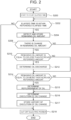
- FIG. 2 is a flowchart describing an example of the operation procedures of the controller 10 in the present embodiment.
- the operating procedures in FIG. 2 are carried out by the control unit 13, when the electric power source circuit 14 supplies electric power to the controller 10 upon reception of a signal indicating that the hood is opened from the hood sensor, and thereby the controller 10 is started.
- the procedures in FIG. 2 are the procedures in the case of determining that oil change is executed by detecting a decrease in remaining oil amount as a discharge indication event and detecting an increase in remaining oil amount as a replenishment indication event.
- step S200 the control unit 13 starts to count elapsed time. Then, when the elapsed time is within reference elapsed time (Yes in step S202), the control unit 13 proceeds to step S204.
- the reference elapsed time is typically the time required for oil change operation.
- the reference elapsed time is preset and stored in the storage unit 12.
- step S218 the control unit 13 cuts off electric power to the controller 10, and ends the procedures in FIG. 2 .
- step S204 the control unit 13 detects the remaining oil amount, and stores it in the storage unit 12.
- the control unit 13 detects the remaining oil amount based on information received from the oil level sensor via the communication unit 11 and stores information on the detected remaining oil amount in the storage unit 12. Then, when it is determined that there is change in remaining oil amount (Yes in step S206), the control unit 13 proceeds to step S210.
- the control unit 13 calculates a difference corresponding to any elapsed time from the information on the remaining oil amount stored in the storage unit 12. When the difference is equal to or more than a reference amount that is optionally set in advance, the control unit 13 determines that there is change in remaining oil amount. When the difference is less than the reference amount, the control unit 13 determines that there is no change in remaining oil amount. When it is determined that there is no change in remaining oil amount (No in step S206), the control unit 13 returns to step S202.
- step S210 the control unit 13 determines whether the remaining oil amount is equal to or less than a decrease reference amount.
- the decrease reference amount is a reference amount indicating that there is a high probability that an oil tank is empty or close to empty when the remaining oil amount is equal to or less than the pertinent amount.
- the decrease reference amount is set to values close to a lower limit of the remaining oil amount that can be detected.
- step S214 determines in step S214 whether the remaining oil amount is equal to or more than an increase reference amount.
- the increase reference amount is a reference amount indicating that there is a high probability that the oil tank is replenished with oil when the remaining oil amount reaches the pertinent amount.
- the increase reference amount is optionally set.
- the increase reference amount may be identical to or different from the decrease reference amount.
- step S216 when the remaining oil amount decreases below the decrease reference amount, that is, when the discharge indication event indicating that oil is discharged with a high probability is detected, or when the remaining oil amount increases beyond the increase reference amount, that is, when the replenishment indication event indicating that oil is replenished with a high probability is detected, the control unit 13 determines that oil change is executed. Alternatively, when it is detected that the remaining oil amount decreases below the decrease reference amount and then the remaining oil amount recovers to the increase reference amount or higher, that is, when both the discharge indication event and the replenishment indication event are detected, the control unit 13 determines that oil change is executed, and creates information that is weighted with the certainty of execution of oil change.
- the oil change is indicated with a higher probability than when each event is detected solely.
- the information weighted with the certainty of execution of oil change is a score, or the like, indicating the certainty in numerical magnitude.
- the control unit 13 stores in the storage unit 12 the history of oil change, or the information indicating the weighted certainty in addition to the history of oil change.
- the history of oil change includes the date and time when execution of the oil change is determined.
- step S218 the control unit 13 cuts off electric power to the controller 10, and ends the procedures in FIG. 2 .
- the controller 10 can determine the execution of oil change and store the history of oil change by detecting a decrease in remaining oil amount as the discharge indication event and an increase in remaining oil amount as the replenishment indication event. In short, it becomes possible to support management of the history of oil change without the need for additional component members for directly detecting one of oil discharge and oil replenishment. Moreover, the increase reference amount corresponding to the increase in remaining oil amount may be set higher than the decrease reference amount corresponding to the decrease in remaining oil amount.
- the controller 10 may be configured such that when the control unit 13 receives a signal indicating that the ignition is turned off via the communication unit 11, minimum required electric power is continuously provided to the controller 10 in accordance with the state of the vehicle 1 at the time. For example, when the control unit 13 receives information indicating engine friction from an engine management ECU via the communication unit 11, and the degree of the friction is large enough to indicate deterioration of engine oil, the control unit 13 performs control to continuously receive electric power supply.
- control unit 13 When the control unit 13 receives a travel distance from an ECU for controlling a travel distance meter via the communication unit 11, and the travel distance is long enough that oil change is recommended (e.g. 5000 km), the control unit 13 also performs control to continuously receive electric power supply. The control unit 13 also performs control to continuously receive electric power supply, when receiving via the communication unit 11 an alert indicating that the remaining oil amount is too small from an ECU for alert control of an engine oil system. Alternatively, when the control unit 13 derives its current position based on the GNSS signals received via the communication unit 11 and map information read from the storage unit 12, and the vehicle 1 is located in a service facility where vehicle maintenance is available, the control unit 13 performs control to continuously receive electric power supply. This makes it possible to bypass the electric power source circuit 14 that controls electric power supply in response to a signal from the hood sensor. In this case, step S200 is executed in response to, for example, ignition turned off.
- FIG. 3 is a flowchart describing an example of the operation procedures of the controller 10 in a first modification.
- the procedures in FIG. 3 is intended to be used in the case of executing oil change for the vehicle 1 at a sales agent of the vehicle 1 or a third party service facility.
- oil change is executed at a service facility, the vehicle 1 is lifted up by a jack or other equipment, and a container is disposed under the body of the vehicle 1 for collecting the oil to be discharged. In this state, discharge of the oil is carried out.
- the weight of the vehicle 1 applied to the suspension of the vehicle 1 is temporarily reduced. Consequently, when the vehicle 1 is returned to the ground, the suspension is in a state of being partially extended.
- the control unit 13 detects the extension of the suspension as the discharge indication event.
- the vehicle 1 staying at a service facility indicates that maintenance of the vehicle body is carried out.
- the time required for oil change tends to be shorter than the time required for tire change, for example. Therefore, by using the typical time required for oil change as a reference stay time, execution of oil replenishment can be determined when the stay time is within the reference stay time, and execution of tire change or the like can be determined when the stay time exceeds the reference stay time. Accordingly, the control unit 13 detects staying at a service facility without exceeding the reference time as the replenishment indication event.
- the control unit 13 determines the execution of oil change by detecting extension of the suspension of the vehicle 1 as the discharge indication event, and detecting staying at a service facility without exceeding the reference stay time as the replenishment indication event.
- the operation procedures in FIG. 3 is executed by the control unit 13 when the service facility finishes maintenance of the vehicle 1, the ignition is turned on, and electric power is supplied to the controller 10 to start the controller 10.
- the vehicle 1 receives maintenance service at a service facility, the ignition is temporarily turned off.
- the control unit 13 stores the current time and date in the storage unit 12 using a spare electric power source, and then ends the operation. Then, when the ignition is turned on and the controller 10 is started after the maintenance service is finished, the control unit 13 executes step S300.
- step S300 the control unit 13 detects the current position, current time and date, and the extension amount of the suspension.
- the control unit 13 receives GNSS signals from the communication unit 11, reads map information from the storage unit 12, and derives the current position using the GNSS signals and the map information.
- the control unit 13 also receives a detection result from a suspension sensor via the communication unit 11 to detect the extension amount of the suspension.
- step S302 the control unit 13 determines whether the current position is in a service facility. Information on service facilities where oil change is available is previously included in the map information. The control unit 13 determines whether the current position matches the position of a service facility. When the current position is in the service facility (Yes in step S302), the control unit 13 proceeds to step S304. When the current position is not in the service facility (No in step S302), the control unit 13 proceeds to S306 without executing steps S304, S305.
- step S304 the control unit 13 determines whether the stay time is within the reference time.
- the control unit 13 calculates the stay time by calculating a difference between ignition-off time stored in the storage unit 12 and the current time.
- the reference stay time is typically the time required for oil change.
- the reference stay time is optionally set (for example, 10 minutes to 20 minutes) and stored in the storage unit 12 in advance.
- the control unit 13 reads the reference stay time from the storage unit 12 and compares it with the calculated stay time. When the stay time is within the reference stay time (Yes in step S304), the control unit 13 proceeds to step S305.
- step S305 the control unit 13 determines that oil is replenished, and proceeds to step S306.
- the stay time exceeds the reference stay time (No in step S304)
- the control unit 13 proceeds to step S306 without executing step S305.
- step S306 the control unit 13 determines whether the extension amount of the suspension is equal to or more than a reference extension amount.
- the reference extension amount is the amount of extension that can be used to indicate that the vehicle body of the vehicle is once lifted up and then lowered to the ground based on a standard extension amount when the wheels of the vehicle 1 are on the ground.
- the reference extension amount is optionally set and stored in the storage unit 12 in advance.
- the control unit 13 reads the reference extension amount from the storage unit 12 and compares it with a detected extension amount of the suspension.
- step S307 the control unit 13 determines that oil is discharged, and proceeds to step S308.
- the extension amount of the suspension is less than the reference extension amount (No in step S306), the control unit 13 proceeds to step S308 without executing step S307.
- step S308 the control unit 13 determines execution of oil change when detecting, as the discharge indication event, that the suspension is extended beyond the reference extension amount or when detecting, as the replenishment indication event, that the vehicle 1 is staying at a service facility without exceeding the reference stay time.
- the control unit 13 determines execution of oil change, and creates information that is weighted with certainty of the execution of oil change.
- step S310 the control unit 13 stores in the storage unit 12 the history of oil change, or information indicating the certainty in addition to the history of oil change.
- step S312 the control unit 13 cuts off electric power to the controller 10, and ends the procedures in FIG. 3 .
- the controller 10 detects extension of the suspension of the vehicle 1 as the discharge indication event, and detects staying at a service facility without exceeding the reference stay time as the replenishment indication event. This makes it possible to support management of the history of oil change without the need for additional component members for directly detecting one of oil discharge and oil replenishment.
- the current date belonging to a reference period is determined as the discharge indication event.
- the reference period is a period (for example, from April to October in Japan) when there is a low probability of needing to fit snow tires.
- the reference period is optionally set.
- the control unit 13 determines that the current date belongs to the reference period as the discharge indication event.
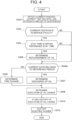
- FIG. 4 is a flowchart describing an example of the operation procedures of the controller 10 in the second modification.
- the procedures in FIG. 4 is intended to be used in the case of executing oil change for the vehicle 1 at a sales agent of the vehicle 1 or a third party service facility.
- the steps identical to the procedures in FIG. 3 are denoted by identical signs.
- step S306a is executed after step S305.
- step S309 is added.
- step S306a the control unit 13 determines whether the current date belongs to a reference period.
- the reference period is optionally set and stored in the storage unit 12 in advance.
- the control unit 13 reads the reference period from the storage unit 12.
- the control unit 13 proceeds to step S307.
- the procedures subsequent to step S307 are the same as the procedures in FIG. 3 .
- the control unit 13 determines execution of tire change in step S309, and proceeds to step S308.
- the controller 10 detects, as the discharge indication even, that the current date belongs to the reference period and the vehicle 1 is staying at a service facility for replenishment of oil rather than for tire change and detects, as the replenishment indication event, that the vehicle 1 is staying at the service facility without exceeding the reference stay time.
- the trip meter of the vehicle 1 may be cleared and reset when oil change for the vehicle 1 is executed.
- the storage unit 12 stores a history of trip meter clear when the trip meter of the vehicle is cleared, together with the history of oil change.
- the control unit 13 determines execution of oil change even without detection of the discharge indication event and the replenishment indication event.
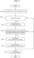
- FIG. 5 is a flowchart describing an example of the operation procedures of the controller 10 in a third modification.
- the control unit 13 executes the procedures at any interval (every few seconds to several hours).
- step S500 the control unit 13 acquires a trip meter value, and stores it in the storage unit 12. For example, the control unit 13 receives a current trip meter value at the point of time from the trip meter or a drive control ECU via the communication unit 11. The control unit 13 stores the received trip meter value in the storage unit 12.
- step S502 the control unit 13 determines whether the trip meter is cleared.
- the control unit 13 reads a recent past trip meter value from the storage unit 12 and compares it with the trip meter value acquired in step S500.
- the control unit 13 determines that the trip meter is cleared when the acquired trip meter value is zero or less than the recent trip meter value.
- the control unit 13 proceeds to step S504 and stores a history of trip meter clear in the storage unit 12.
- the history of trip meter clear includes, for example, the date and time when the trip meter clear is determined.
- the control unit 13 proceeds to step S512.
- step S512 the control unit 13 cuts off electric power to the controller 10, and ends the procedures in FIG. 5 .
- step S506 the control unit 13 determines whether simultaneous execution of the trip meter clear and oil change is performed at a reference frequency or more.
- the simultaneous execution induces execution of the trip meter clear and oil change on the same date.
- the frequency is, for example, a ratio of the number of simultaneous execution to the number of execution of oil change.
- the control unit 13 reads the history of trip meter clear and the history of oil change in the past from the storage unit 12, and counts the number of simultaneous execution of the trip meter clear and oil change on the same date.
- the control unit 13 then calculates the frequency of the simultaneous execution, and compares the frequency of the simultaneous execution with a reference frequency.
- the reference frequency is the frequency (e.g.
- step S506 the control unit 13 proceeds to step S508 to determine execution of oil change.
- step S510 the control unit 13 stores the history of oil change in the storage unit 12.
- step S512 the control unit 13 proceeds to step S512 to cut off electric power to the controller 10, and ends the procedures in FIG. 5 .
- the controller 10 can determine the execution of oil change without detecting the discharge indication event and the replenishment indication event.
- the controller 10 detects a decrease in remaining oil amount as the discharge indication event, and detects an increase after a decrease in remaining oil amount as the replenishment indication event. Therefore, the controller 10 determine the execution of oil change based on detection of a relatively direct event such as increase or decrease of the remaining oil amount.
- the controller 10 determines oil change based on a relatively indirect event as compared with the increase or decrease in remaining oil amount. Therefore, when the procedures in FIG. 2 is compared with the procedures in FIGS 3 to 5 , there is a difference in certainty of determination regarding oil change.
- the certainty of determination regarding oil change is enhanced by combing the procedures in FIGS. 3 to 5 .
- the procedures in FIG. 6 are a combination of the procedures in FIGS. 3 to 5 .
- Subroutines in steps S600, S602, S604 correspond to the procedures in FIGS. 3 to 5 , respectively.
- the control unit 13 adds an evaluation point indicating the certainty of oil change instead of determining the oil change.
- the evaluation point is any discrete number.
- the evaluation points may be different in magnitude.
- the control unit 13 may add an evaluation point the magnitude of which corresponds to the frequency of simultaneous execution of trip meter clear and oil change.
- the control unit 13 executes steps S600, S602, S604 in sequence. Furthermore in step S606, the control unit 13 determines whether the magnitude of engine friction is within a reference friction value.
- the control unit 13 acquires information indicating the magnitude of torque from the engine control ECU via the communication unit 11, and calculates the engine friction from the magnitude of torque.
- the engine friction is small when the engine oil is fresh.
- the reference value is set to any friction value when oil change is executed and the engine is filled with new engine oil.
- the reference value is stored in the storage unit 12 in advance.
- the control unit 13 reads a reference friction value from the storage unit 12, and compares it with the detected engine friction.
- step S606 When the engine friction is within the reference friction value (Yes in step S606), the control unit 13 proceeds to step S608 to add an evaluation point indicating the certainty of oil change. When the engine friction exceeds the reference friction value (No in step S606), the control unit 13 omits step S608.
- step S610 the control unit 13 determines execution of oil change based on the evaluation point. For example, the control unit 13 determines that oil change is executed when a sum of the added evaluation points exceeds a preset reference evaluation point, and when the sum of the added evaluation points is equal to or less than the reference evaluation point, the control unit 13 determines that oil change is not executed. Alternatively, the control unit 13 may determine execution of oil change with information indicating the certainty corresponding to the evaluation point. For example, the evaluation points may be ranked into A, B, C in order of certainty, and execution of oil change is determined with reservation by ranking. Then, in step S612, the control unit 13 stores the history of oil change in the storage unit 12.
- step S614 the control unit 13 cuts off electric power to the controller 10, and ends the procedures in FIG. 6 .
- steps S600, S602, S604, S606 are exemplary. It is possible to execute one or more of the steps in any order.
- the procedures shown in FIGS. 2 to 5 can be executed in any appropriate combination, or can be executed with the order of the steps in the respective procedures being changed.
- the history of oil change stored in the storage unit 12, or information indicating the certainty of the execution of oil change in addition to the history of oil change can be read as appropriate using any user interface.
- the user can read the history of oil change from the storage unit 12 of the controller 10 via the in-vehicle network of the vehicle 1 by operating a terminal device that can be connected to the in-vehicle network.
- the controller 10 is constituted of a navigation device or other information processing devices including a user interface
- the user can read the history of oil change from the storage unit 12 attached thereto by operating the user interface of the information processing device.
- a cloud server may be configured to include part of the storage unit 12.
- control unit 13 of the controller 10 sends the history of oil change or the like to the cloud server via the communication unit 11, and the history is centrally stored on the cloud server.
- the user can read the history of oil change from the cloud server by operating an information processing device such as personal computers connected to the cloud server via the network.
- Processing and control programs are commands that define the operation of the controller 10 and cause the controller 10 to execute control and processing functions.
- the processing and control programs may be stored in the storage unit of any server device and be downloaded to the controller 10, or may be stored in a portable, non-transitory recording and storage medium that is readable by the controller 10, and the controller 10 may read them from the medium.
Landscapes
- Engineering & Computer Science (AREA)
- Mechanical Engineering (AREA)
- General Engineering & Computer Science (AREA)
- Chemical & Material Sciences (AREA)
- Combustion & Propulsion (AREA)
- Transportation (AREA)
- Physics & Mathematics (AREA)
- General Physics & Mathematics (AREA)
- Lubrication Details And Ventilation Of Internal Combustion Engines (AREA)
- Combined Controls Of Internal Combustion Engines (AREA)
- Time Recorders, Dirve Recorders, Access Control (AREA)
Claims (14)
- Steuergerät (10), umfassend:eine Steuereinheit (13), die dazu ausgestaltet ist, basierend auf Informationen von einem Sensor (16), der an einem Fahrzeug (1) montiert ist, ein erstes Ereignis, das angibt, dass Motoröl von einem Motor des Fahrzeugs (1) abgelassen wird, oder ein zweites Ereignis zu erfassen, das angibt, das der Motor mit Motoröl aufgefüllt wird, undeine Speichereinheit (12), die dazu ausgestaltet ist, ein Ergebnis der Erfassung durch die Steuereinheit (13) als einen Verlauf eines Ölwechsels zu speichern, wobei:das Steuergerät (10) gestartet wird, wenn die Motorhaube des Fahrzeugs geöffnet wird, unddie Steuereinheit (13) dazu ausgestaltet ist, wenn eine Referenz-Ablaufzeit nach dem Starten des Steuergeräts (10) abläuft, den elektrischen Strom zu dem Steuergerät (10) selbst ohne Erfassung des ersten Ereignisses oder des zweiten Ereignisses abzuschalten.
- Steuergerät (10) nach Anspruch 1, wobei:das erste Ereignis eine Abnahme der Menge des Motoröls beinhaltet, unddas zweite Ereignis eine Zunahme der Menge des Motoröls beinhaltet.
- Steuergerät (10) nach Anspruch 2, wobei:das zweite Ereignis eine Zunahme nach einer Abnahme der Menge des Motoröls beinhaltet,
unddie Steuereinheit (13) dazu ausgestaltet ist, wenn das zweite Ereignis erfasst wird, Informationen zu speichern, die eine Gewissheit des Verlaufs des Ölwechsels in der Speichereinheit (12) angeben. - Steuergerät (10) nach Anspruch 2 oder 3, wobei:die Abnahme der Menge des Motoröls in dem ersten Ereignis unter der Bedingung stattfindet, dass die Menge des Motoröls gleich wie oder weniger als eine erste Referenzmenge wird, unddie Zunahme der Menge des Motoröls in dem zweiten Ereignis unter der Bedingung stattfindet, dass die Menge des Motoröls gleich wie oder mehr als eine zweite Referenzmenge wird.
- Steuergerät (10) nach Anspruch 4, wobei die zweite Referenzmenge größer ist als die erste Referenzmenge.
- Steuergerät (10) nach einem der Ansprüche 1 bis 5, wobei:die Speichereinheit (12) dazu ausgestaltet ist, ein Löschen des Tageskilometerzählerverlaufes, wenn ein Tageskilometerzähler des Fahrzeugs (1) gelöscht wird, zusammen mit dem Verlauf des Ölwechsels zu speichern, unddie Steuereinheit (13) dazu ausgestaltet ist, den Verlauf des Ölwechsels in der Speichereinheit (12) selbst ohne Erfassung des ersten Ereignisses oder des zweiten Ereignisses zu speichern, wenn das Löschen des Tageskilometerzählers erfasst wird und der Verlauf des Löschens des Tageskilometerzählers dem Verlauf des Ölwechsels bei einer Referenzfrequenz oder mehr in der Vergangenheit zugeordnet ist.
- Fahrzeug, umfassend das Steuergerät (10) nach einem der Ansprüche 1 bis 6.
- Nichtflüchtiges Speichermedium zum Speichern von Befehlen, die von einem oder mehreren Prozessoren ausführbar sind und die bewirken, dass der eine oder die mehreren Prozessoren Funktionen durchführen, die das Bewirken umfassen, dass ein Computer als das Steuergerät (10) nach einem der Ansprüche 1 bis 6 arbeitet.
- Betriebsverfahren eines Steuergeräts (10), umfassend:Empfangen von Informationen von Vorrichtungen, die einen Sensor (16) beinhalten, der an einem Fahrzeug (1) montiert ist,Erfassen, basierend auf den Informationen, eines ersten Ereignisses, das angibt, dass Motoröl von einem Motor des Fahrzeugs (1) abgelassen wird, oder eines zweiten Ereignisses, das angibt, dass der Motor mit Motoröl aufgefüllt wird, undSpeichern eines Ergebnisses der Erfassung als einen Verlauf eines Ölwechsels, wobei das Verfahren ferner umfasst:Starten des Steuergeräts (10), wenn die Motorhaube des Fahrzeugs (1) geöffnet wird, undAbschalten, wenn eine Referenz-Ablaufzeit nach dem Starten des Steuergeräts (10) abläuft, des elektrischen Stroms zu dem Steuergerät (10) selbst ohne Erfassung des ersten Ereignisses oder des zweiten Ereignisses.
- Betriebsverfahren nach Anspruch 9, wobei:das erste Ereignis eine Abnahme der Menge des Motoröls beinhaltet, unddas zweite Ereignis eine Zunahme der Menge des Motoröls beinhaltet.
- Betriebsverfahren nach Anspruch 10, wobei:das zweite Ereignis eine Zunahme nach einer Abnahme der Menge des Motoröls beinhaltet,
und,wenn das zweite Ereignis erfasst wird, das Betriebsverfahren ferner das Speichern von Informationen beinhaltet, die eine Gewissheit des Verlaufes des Ölwechsels angeben. - Betriebsverfahren nach Anspruch 10 oder 11, wobei:die Abnahme der Menge des Motoröls in dem ersten Ereignis unter der Bedingung stattfindet, dass die Menge des Motoröls gleich wie oder weniger als eine erste Referenzmenge wird, unddie Zunahme der Menge des Motoröls in dem zweiten Ereignis unter der Bedingung stattfindet, dass die Menge des Motoröls gleich wie oder mehr als eine zweite Referenzmenge wird.
- Betriebsverfahren nach Anspruch 12, wobei die zweite Referenzmenge größer ist als die erste Referenzmenge.
- Betriebsverfahren nach Anspruch 9. wobei:das erste Ereignis beinhaltet, dass ein Umfang einer Unterbrechung, wenn eine Zündung des Fahrzeugs (1) eingeschaltet wird, gleich wie oder größer als ein Referenzumfang ist, unddas zweite Ereignis beinhaltet, dass das Fahrzeug (1) an einem vorgeschriebenen Platz verweilt, ohne eine Referenzverweilzeit zu überschreiten.
Applications Claiming Priority (1)
| Application Number | Priority Date | Filing Date | Title |
|---|---|---|---|
| JP2020199038A JP7359132B2 (ja) | 2020-11-30 | 2020-11-30 | 制御装置、車両、プロブラム及び制御装置の動作方法 |
Publications (2)
| Publication Number | Publication Date |
|---|---|
| EP4006318A1 EP4006318A1 (de) | 2022-06-01 |
| EP4006318B1 true EP4006318B1 (de) | 2024-01-31 |
Family
ID=77864501
Family Applications (1)
| Application Number | Title | Priority Date | Filing Date |
|---|---|---|---|
| EP21197972.9A Active EP4006318B1 (de) | 2020-11-30 | 2021-09-21 | Steuergerät, fahrzeug, speichermedium und betriebsverfahren eines steuergeräts |
Country Status (6)
| Country | Link |
|---|---|
| US (1) | US11624301B2 (de) |
| EP (1) | EP4006318B1 (de) |
| JP (1) | JP7359132B2 (de) |
| KR (1) | KR20220076292A (de) |
| CN (1) | CN114576019B (de) |
| BR (1) | BR102021020158A2 (de) |
Families Citing this family (1)
| Publication number | Priority date | Publication date | Assignee | Title |
|---|---|---|---|---|
| JP7359132B2 (ja) * | 2020-11-30 | 2023-10-11 | トヨタ自動車株式会社 | 制御装置、車両、プロブラム及び制御装置の動作方法 |
Family Cites Families (30)
| Publication number | Priority date | Publication date | Assignee | Title |
|---|---|---|---|---|
| US4706193A (en) * | 1985-02-12 | 1987-11-10 | Nissan Motor Company, Limited | Oil degradation warning system |
| JPH0756208B2 (ja) * | 1985-09-05 | 1995-06-14 | 日産自動車株式会社 | 車両用潤滑油交換警告装置 |
| JPS61272410A (ja) * | 1985-05-28 | 1986-12-02 | Nissan Motor Co Ltd | 車両用潤滑油交換時期警告装置 |
| JPH05171911A (ja) | 1991-12-24 | 1993-07-09 | Calsonic Corp | オイル劣化検出装置 |
| US5749339A (en) * | 1996-02-28 | 1998-05-12 | Cummins Engine Company, Inc. | Electronically controlled continuous lubricating oil replacement system |
| US6484127B1 (en) | 2000-11-27 | 2002-11-19 | Volvo Trucks North America, Inc. | Oil maintenance indicator |
| US6853954B2 (en) | 2002-09-24 | 2005-02-08 | John K. Apostolides | Methods and systems for collecting and processing data in association with machine operation and maintenance |
| JP2004150375A (ja) * | 2002-10-31 | 2004-05-27 | Honda Motor Co Ltd | エンジンオイルの劣化判定装置 |
| US6977583B2 (en) * | 2003-09-09 | 2005-12-20 | General Motors Corporation | Automatic reset of lubricating fluid life monitoring system |
| US8746408B2 (en) * | 2006-09-01 | 2014-06-10 | GM Global Technology Operations LLC | Engine oil change detection systems and methods |
| US7614284B2 (en) * | 2007-01-08 | 2009-11-10 | Gm Global Technology Operations, Inc. | Oil life monitoring system for a diesel engine |
| US7900507B2 (en) * | 2007-09-28 | 2011-03-08 | University Of Dayton | Device and method for monitoring the quality of an oil change and condition of engine oil from an oil change |
| US8126607B2 (en) * | 2008-10-30 | 2012-02-28 | International Business Machines Corporation | Vehicle fluid replacement tracking |
| JP5609185B2 (ja) * | 2010-03-18 | 2014-10-22 | トヨタ自動車株式会社 | オイル異常診断装置 |
| FR2961252B1 (fr) * | 2010-06-09 | 2015-10-16 | Peugeot Citroen Automobiles Sa | Procede de detection de la realisation d'une vidange pour un moteur a combustion interne |
| US8707773B2 (en) * | 2010-08-17 | 2014-04-29 | GM Global Technology Operations LLC | Method of monitoring oil in a vehicle |
| US9388716B2 (en) * | 2012-06-20 | 2016-07-12 | GM Global Technology Operations LLC | Systems and methods for accurately compensating for a change in amount of unwanted fluid diluted in engine oil resulting from a recent long trip |
| CN106927416B (zh) * | 2015-12-29 | 2019-08-02 | 长城汽车股份有限公司 | 一种油液加注系统及方法 |
| US9984514B2 (en) * | 2016-01-29 | 2018-05-29 | Toyota Motor Engineering & Manufacturing North America, Inc. | Vehicle fluid replacement monitoring system and method |
| CN106801636B (zh) * | 2017-02-10 | 2019-04-09 | 百发动力(无锡)有限公司 | 一种自动补给更换机油的方法 |
| JP6717241B2 (ja) * | 2017-03-09 | 2020-07-01 | 株式会社オートネットワーク技術研究所 | 車両消耗品管理システム、端末装置、コンピュータプログラム及び車両消耗品管理方法 |
| US10573094B2 (en) * | 2017-04-25 | 2020-02-25 | International Business Machines Corporation | Capturing vehicle fluid change history |
| CN208871320U (zh) * | 2018-09-14 | 2019-05-17 | 李明权 | 一种机油自动加注装置 |
| CN109184853B (zh) * | 2018-09-19 | 2020-12-25 | 中北大学 | 汽车机油的自动测量控制装置 |
| JP7213107B2 (ja) | 2019-03-06 | 2023-01-26 | 本田技研工業株式会社 | 車両位置分析装置及び車両位置分析方法 |
| CN110173324A (zh) * | 2019-07-12 | 2019-08-27 | 山东职业学院 | 一种机油液位高度测量装置及方法 |
| CN111042893A (zh) | 2019-12-20 | 2020-04-21 | 中联重科股份有限公司 | 用于发动机的机油自动加注控制方法、系统及工程机械 |
| JP7272292B2 (ja) * | 2020-01-27 | 2023-05-12 | いすゞ自動車株式会社 | オイル交換案内装置及びオイル交換案内方法 |
| CN111664905A (zh) * | 2020-06-20 | 2020-09-15 | 河南柴油机重工有限责任公司 | 一种柴油机机油消耗量测量装置、测量方法及应用 |
| JP7359132B2 (ja) * | 2020-11-30 | 2023-10-11 | トヨタ自動車株式会社 | 制御装置、車両、プロブラム及び制御装置の動作方法 |
-
2020
- 2020-11-30 JP JP2020199038A patent/JP7359132B2/ja active Active
-
2021
- 2021-09-17 US US17/478,286 patent/US11624301B2/en active Active
- 2021-09-21 EP EP21197972.9A patent/EP4006318B1/de active Active
- 2021-09-27 CN CN202111136540.9A patent/CN114576019B/zh active Active
- 2021-09-28 KR KR1020210127639A patent/KR20220076292A/ko not_active Withdrawn
- 2021-10-07 BR BR102021020158-4A patent/BR102021020158A2/pt not_active IP Right Cessation
Also Published As
| Publication number | Publication date |
|---|---|
| JP7359132B2 (ja) | 2023-10-11 |
| KR20220076292A (ko) | 2022-06-08 |
| US20220172526A1 (en) | 2022-06-02 |
| US11624301B2 (en) | 2023-04-11 |
| BR102021020158A2 (pt) | 2023-01-31 |
| JP2022086813A (ja) | 2022-06-09 |
| CN114576019A (zh) | 2022-06-03 |
| EP4006318A1 (de) | 2022-06-01 |
| CN114576019B (zh) | 2024-08-23 |
Similar Documents
| Publication | Publication Date | Title |
|---|---|---|
| US11041734B2 (en) | Systems and methods for optimizing a travel route of a hybrid-electric vehicle inside an emissions-free zone | |
| US11187753B2 (en) | System and method for determining a status of a vehicle battery | |
| US20110046842A1 (en) | Satellite enabled vehicle prognostic and diagnostic system | |
| CN112622881A (zh) | 一种智能泊车方法、装置、系统、存储介质及车辆 | |
| US20100063717A1 (en) | Methods and systems for monitoring fuel status of vehicles | |
| US20030117273A1 (en) | On-vehicle emergency report apparatus, emergency communication apparatus and emergency report system | |
| JP5929444B2 (ja) | 車載用報知装置 | |
| CN111275940B (zh) | 车载定位设备被恶意拆除的识别方法以及终端设备 | |
| US10145881B1 (en) | Autonomous vehicle maintenance self-charge | |
| EP4006318B1 (de) | Steuergerät, fahrzeug, speichermedium und betriebsverfahren eines steuergeräts | |
| US20200160407A1 (en) | Server apparatus and information providing method | |
| US20070126559A1 (en) | Vehicular abnormality notification system, method and apparatus, and vehicle-mounted apparatus | |
| US20020133271A1 (en) | Virtual odometer system and method | |
| CN117435889B (zh) | 一种电力电缆在线故障监测预警方法以及系统 | |
| CN117561527A (zh) | 修理地点发送装置及修理地点发送方法 | |
| US20200159199A1 (en) | Server apparatus and information providing method | |
| WO2004086332A1 (ja) | 車両情報提供方法、車両情報提供システム、情報端末装置およびセンター | |
| JP2002211217A (ja) | タイヤ空気圧警報システム | |
| EP3974267B1 (de) | System und verfahren zur positionsschätzung | |
| JP6308633B2 (ja) | 充電要否判定システム、車載装置及び電気自動車 | |
| JP4266949B2 (ja) | 輸送品質サポートシステム | |
| EP1398748B1 (de) | Kommunikationsendgerät für Fahrzeuge | |
| JP4466554B2 (ja) | 車載無線通信装置および車載端末装置 | |
| US20230298392A1 (en) | Replacement time calculation system and replacement time calculation method | |
| US12202494B2 (en) | Information processing apparatus, method, and storage medium |
Legal Events
| Date | Code | Title | Description |
|---|---|---|---|
| PUAI | Public reference made under article 153(3) epc to a published international application that has entered the european phase |
Free format text: ORIGINAL CODE: 0009012 |
|
| STAA | Information on the status of an ep patent application or granted ep patent |
Free format text: STATUS: REQUEST FOR EXAMINATION WAS MADE |
|
| 17P | Request for examination filed |
Effective date: 20210921 |
|
| AK | Designated contracting states |
Kind code of ref document: A1 Designated state(s): AL AT BE BG CH CY CZ DE DK EE ES FI FR GB GR HR HU IE IS IT LI LT LU LV MC MK MT NL NO PL PT RO RS SE SI SK SM TR |
|
| STAA | Information on the status of an ep patent application or granted ep patent |
Free format text: STATUS: EXAMINATION IS IN PROGRESS |
|
| 17Q | First examination report despatched |
Effective date: 20230307 |
|
| GRAP | Despatch of communication of intention to grant a patent |
Free format text: ORIGINAL CODE: EPIDOSNIGR1 |
|
| STAA | Information on the status of an ep patent application or granted ep patent |
Free format text: STATUS: GRANT OF PATENT IS INTENDED |
|
| INTG | Intention to grant announced |
Effective date: 20230907 |
|
| GRAS | Grant fee paid |
Free format text: ORIGINAL CODE: EPIDOSNIGR3 |
|
| GRAA | (expected) grant |
Free format text: ORIGINAL CODE: 0009210 |
|
| STAA | Information on the status of an ep patent application or granted ep patent |
Free format text: STATUS: THE PATENT HAS BEEN GRANTED |
|
| AK | Designated contracting states |
Kind code of ref document: B1 Designated state(s): AL AT BE BG CH CY CZ DE DK EE ES FI FR GB GR HR HU IE IS IT LI LT LU LV MC MK MT NL NO PL PT RO RS SE SI SK SM TR |
|
| REG | Reference to a national code |
Ref country code: GB Ref legal event code: FG4D Ref country code: CH Ref legal event code: EP |
|
| REG | Reference to a national code |
Ref country code: DE Ref legal event code: R096 Ref document number: 602021008920 Country of ref document: DE |
|
| REG | Reference to a national code |
Ref country code: IE Ref legal event code: FG4D |
|
| REG | Reference to a national code |
Ref country code: LT Ref legal event code: MG9D |
|
| P01 | Opt-out of the competence of the unified patent court (upc) registered |
Effective date: 20240419 |
|
| REG | Reference to a national code |
Ref country code: NL Ref legal event code: MP Effective date: 20240131 |
|
| REG | Reference to a national code |
Ref country code: DE Ref legal event code: R084 Ref document number: 602021008920 Country of ref document: DE |
|
| PG25 | Lapsed in a contracting state [announced via postgrant information from national office to epo] |
Ref country code: IS Free format text: LAPSE BECAUSE OF FAILURE TO SUBMIT A TRANSLATION OF THE DESCRIPTION OR TO PAY THE FEE WITHIN THE PRESCRIBED TIME-LIMIT Effective date: 20240531 |
|
| PG25 | Lapsed in a contracting state [announced via postgrant information from national office to epo] |
Ref country code: LT Free format text: LAPSE BECAUSE OF FAILURE TO SUBMIT A TRANSLATION OF THE DESCRIPTION OR TO PAY THE FEE WITHIN THE PRESCRIBED TIME-LIMIT Effective date: 20240131 |
|
| PG25 | Lapsed in a contracting state [announced via postgrant information from national office to epo] |
Ref country code: GR Free format text: LAPSE BECAUSE OF FAILURE TO SUBMIT A TRANSLATION OF THE DESCRIPTION OR TO PAY THE FEE WITHIN THE PRESCRIBED TIME-LIMIT Effective date: 20240501 |
|
| REG | Reference to a national code |
Ref country code: AT Ref legal event code: MK05 Ref document number: 1654011 Country of ref document: AT Kind code of ref document: T Effective date: 20240131 |
|
| PG25 | Lapsed in a contracting state [announced via postgrant information from national office to epo] |
Ref country code: HR Free format text: LAPSE BECAUSE OF FAILURE TO SUBMIT A TRANSLATION OF THE DESCRIPTION OR TO PAY THE FEE WITHIN THE PRESCRIBED TIME-LIMIT Effective date: 20240131 Ref country code: NL Free format text: LAPSE BECAUSE OF FAILURE TO SUBMIT A TRANSLATION OF THE DESCRIPTION OR TO PAY THE FEE WITHIN THE PRESCRIBED TIME-LIMIT Effective date: 20240131 Ref country code: RS Free format text: LAPSE BECAUSE OF FAILURE TO SUBMIT A TRANSLATION OF THE DESCRIPTION OR TO PAY THE FEE WITHIN THE PRESCRIBED TIME-LIMIT Effective date: 20240430 |
|
| PG25 | Lapsed in a contracting state [announced via postgrant information from national office to epo] |
Ref country code: ES Free format text: LAPSE BECAUSE OF FAILURE TO SUBMIT A TRANSLATION OF THE DESCRIPTION OR TO PAY THE FEE WITHIN THE PRESCRIBED TIME-LIMIT Effective date: 20240131 |
|
| PG25 | Lapsed in a contracting state [announced via postgrant information from national office to epo] |
Ref country code: AT Free format text: LAPSE BECAUSE OF FAILURE TO SUBMIT A TRANSLATION OF THE DESCRIPTION OR TO PAY THE FEE WITHIN THE PRESCRIBED TIME-LIMIT Effective date: 20240131 |
|
| PG25 | Lapsed in a contracting state [announced via postgrant information from national office to epo] |
Ref country code: RS Free format text: LAPSE BECAUSE OF FAILURE TO SUBMIT A TRANSLATION OF THE DESCRIPTION OR TO PAY THE FEE WITHIN THE PRESCRIBED TIME-LIMIT Effective date: 20240430 Ref country code: NO Free format text: LAPSE BECAUSE OF FAILURE TO SUBMIT A TRANSLATION OF THE DESCRIPTION OR TO PAY THE FEE WITHIN THE PRESCRIBED TIME-LIMIT Effective date: 20240430 Ref country code: NL Free format text: LAPSE BECAUSE OF FAILURE TO SUBMIT A TRANSLATION OF THE DESCRIPTION OR TO PAY THE FEE WITHIN THE PRESCRIBED TIME-LIMIT Effective date: 20240131 Ref country code: LT Free format text: LAPSE BECAUSE OF FAILURE TO SUBMIT A TRANSLATION OF THE DESCRIPTION OR TO PAY THE FEE WITHIN THE PRESCRIBED TIME-LIMIT Effective date: 20240131 Ref country code: IS Free format text: LAPSE BECAUSE OF FAILURE TO SUBMIT A TRANSLATION OF THE DESCRIPTION OR TO PAY THE FEE WITHIN THE PRESCRIBED TIME-LIMIT Effective date: 20240531 Ref country code: HR Free format text: LAPSE BECAUSE OF FAILURE TO SUBMIT A TRANSLATION OF THE DESCRIPTION OR TO PAY THE FEE WITHIN THE PRESCRIBED TIME-LIMIT Effective date: 20240131 Ref country code: GR Free format text: LAPSE BECAUSE OF FAILURE TO SUBMIT A TRANSLATION OF THE DESCRIPTION OR TO PAY THE FEE WITHIN THE PRESCRIBED TIME-LIMIT Effective date: 20240501 Ref country code: FI Free format text: LAPSE BECAUSE OF FAILURE TO SUBMIT A TRANSLATION OF THE DESCRIPTION OR TO PAY THE FEE WITHIN THE PRESCRIBED TIME-LIMIT Effective date: 20240131 Ref country code: ES Free format text: LAPSE BECAUSE OF FAILURE TO SUBMIT A TRANSLATION OF THE DESCRIPTION OR TO PAY THE FEE WITHIN THE PRESCRIBED TIME-LIMIT Effective date: 20240131 Ref country code: BG Free format text: LAPSE BECAUSE OF FAILURE TO SUBMIT A TRANSLATION OF THE DESCRIPTION OR TO PAY THE FEE WITHIN THE PRESCRIBED TIME-LIMIT Effective date: 20240131 Ref country code: AT Free format text: LAPSE BECAUSE OF FAILURE TO SUBMIT A TRANSLATION OF THE DESCRIPTION OR TO PAY THE FEE WITHIN THE PRESCRIBED TIME-LIMIT Effective date: 20240131 |
|
| PG25 | Lapsed in a contracting state [announced via postgrant information from national office to epo] |
Ref country code: PL Free format text: LAPSE BECAUSE OF FAILURE TO SUBMIT A TRANSLATION OF THE DESCRIPTION OR TO PAY THE FEE WITHIN THE PRESCRIBED TIME-LIMIT Effective date: 20240131 Ref country code: PT Free format text: LAPSE BECAUSE OF FAILURE TO SUBMIT A TRANSLATION OF THE DESCRIPTION OR TO PAY THE FEE WITHIN THE PRESCRIBED TIME-LIMIT Effective date: 20240531 |
|
| PG25 | Lapsed in a contracting state [announced via postgrant information from national office to epo] |
Ref country code: SE Free format text: LAPSE BECAUSE OF FAILURE TO SUBMIT A TRANSLATION OF THE DESCRIPTION OR TO PAY THE FEE WITHIN THE PRESCRIBED TIME-LIMIT Effective date: 20240131 Ref country code: PT Free format text: LAPSE BECAUSE OF FAILURE TO SUBMIT A TRANSLATION OF THE DESCRIPTION OR TO PAY THE FEE WITHIN THE PRESCRIBED TIME-LIMIT Effective date: 20240531 Ref country code: PL Free format text: LAPSE BECAUSE OF FAILURE TO SUBMIT A TRANSLATION OF THE DESCRIPTION OR TO PAY THE FEE WITHIN THE PRESCRIBED TIME-LIMIT Effective date: 20240131 Ref country code: LV Free format text: LAPSE BECAUSE OF FAILURE TO SUBMIT A TRANSLATION OF THE DESCRIPTION OR TO PAY THE FEE WITHIN THE PRESCRIBED TIME-LIMIT Effective date: 20240131 |
|
| PG25 | Lapsed in a contracting state [announced via postgrant information from national office to epo] |
Ref country code: DK Free format text: LAPSE BECAUSE OF FAILURE TO SUBMIT A TRANSLATION OF THE DESCRIPTION OR TO PAY THE FEE WITHIN THE PRESCRIBED TIME-LIMIT Effective date: 20240131 |
|
| PG25 | Lapsed in a contracting state [announced via postgrant information from national office to epo] |
Ref country code: SM Free format text: LAPSE BECAUSE OF FAILURE TO SUBMIT A TRANSLATION OF THE DESCRIPTION OR TO PAY THE FEE WITHIN THE PRESCRIBED TIME-LIMIT Effective date: 20240131 |
|
| PG25 | Lapsed in a contracting state [announced via postgrant information from national office to epo] |
Ref country code: CZ Free format text: LAPSE BECAUSE OF FAILURE TO SUBMIT A TRANSLATION OF THE DESCRIPTION OR TO PAY THE FEE WITHIN THE PRESCRIBED TIME-LIMIT Effective date: 20240131 Ref country code: EE Free format text: LAPSE BECAUSE OF FAILURE TO SUBMIT A TRANSLATION OF THE DESCRIPTION OR TO PAY THE FEE WITHIN THE PRESCRIBED TIME-LIMIT Effective date: 20240131 |
|
| PG25 | Lapsed in a contracting state [announced via postgrant information from national office to epo] |
Ref country code: SK Free format text: LAPSE BECAUSE OF FAILURE TO SUBMIT A TRANSLATION OF THE DESCRIPTION OR TO PAY THE FEE WITHIN THE PRESCRIBED TIME-LIMIT Effective date: 20240131 |
|
| PG25 | Lapsed in a contracting state [announced via postgrant information from national office to epo] |
Ref country code: SM Free format text: LAPSE BECAUSE OF FAILURE TO SUBMIT A TRANSLATION OF THE DESCRIPTION OR TO PAY THE FEE WITHIN THE PRESCRIBED TIME-LIMIT Effective date: 20240131 Ref country code: SK Free format text: LAPSE BECAUSE OF FAILURE TO SUBMIT A TRANSLATION OF THE DESCRIPTION OR TO PAY THE FEE WITHIN THE PRESCRIBED TIME-LIMIT Effective date: 20240131 Ref country code: RO Free format text: LAPSE BECAUSE OF FAILURE TO SUBMIT A TRANSLATION OF THE DESCRIPTION OR TO PAY THE FEE WITHIN THE PRESCRIBED TIME-LIMIT Effective date: 20240131 Ref country code: EE Free format text: LAPSE BECAUSE OF FAILURE TO SUBMIT A TRANSLATION OF THE DESCRIPTION OR TO PAY THE FEE WITHIN THE PRESCRIBED TIME-LIMIT Effective date: 20240131 Ref country code: DK Free format text: LAPSE BECAUSE OF FAILURE TO SUBMIT A TRANSLATION OF THE DESCRIPTION OR TO PAY THE FEE WITHIN THE PRESCRIBED TIME-LIMIT Effective date: 20240131 Ref country code: CZ Free format text: LAPSE BECAUSE OF FAILURE TO SUBMIT A TRANSLATION OF THE DESCRIPTION OR TO PAY THE FEE WITHIN THE PRESCRIBED TIME-LIMIT Effective date: 20240131 |
|
| REG | Reference to a national code |
Ref country code: DE Ref legal event code: R097 Ref document number: 602021008920 Country of ref document: DE |
|
| PG25 | Lapsed in a contracting state [announced via postgrant information from national office to epo] |
Ref country code: IT Free format text: LAPSE BECAUSE OF FAILURE TO SUBMIT A TRANSLATION OF THE DESCRIPTION OR TO PAY THE FEE WITHIN THE PRESCRIBED TIME-LIMIT Effective date: 20240131 |
|
| PLBE | No opposition filed within time limit |
Free format text: ORIGINAL CODE: 0009261 |
|
| STAA | Information on the status of an ep patent application or granted ep patent |
Free format text: STATUS: NO OPPOSITION FILED WITHIN TIME LIMIT |
|
| PG25 | Lapsed in a contracting state [announced via postgrant information from national office to epo] |
Ref country code: IT Free format text: LAPSE BECAUSE OF FAILURE TO SUBMIT A TRANSLATION OF THE DESCRIPTION OR TO PAY THE FEE WITHIN THE PRESCRIBED TIME-LIMIT Effective date: 20240131 |
|
| 26N | No opposition filed |
Effective date: 20241101 |
|
| PG25 | Lapsed in a contracting state [announced via postgrant information from national office to epo] |
Ref country code: SI Free format text: LAPSE BECAUSE OF FAILURE TO SUBMIT A TRANSLATION OF THE DESCRIPTION OR TO PAY THE FEE WITHIN THE PRESCRIBED TIME-LIMIT Effective date: 20240131 Ref country code: MC Free format text: LAPSE BECAUSE OF FAILURE TO SUBMIT A TRANSLATION OF THE DESCRIPTION OR TO PAY THE FEE WITHIN THE PRESCRIBED TIME-LIMIT Effective date: 20240131 |
|
| REG | Reference to a national code |
Ref country code: CH Ref legal event code: PL |
|
| PG25 | Lapsed in a contracting state [announced via postgrant information from national office to epo] |
Ref country code: LU Free format text: LAPSE BECAUSE OF NON-PAYMENT OF DUE FEES Effective date: 20240921 |
|
| REG | Reference to a national code |
Ref country code: BE Ref legal event code: MM Effective date: 20240930 |
|
| PG25 | Lapsed in a contracting state [announced via postgrant information from national office to epo] |
Ref country code: BE Free format text: LAPSE BECAUSE OF NON-PAYMENT OF DUE FEES Effective date: 20240930 |
|
| PG25 | Lapsed in a contracting state [announced via postgrant information from national office to epo] |
Ref country code: FR Free format text: LAPSE BECAUSE OF NON-PAYMENT OF DUE FEES Effective date: 20240930 |
|
| PG25 | Lapsed in a contracting state [announced via postgrant information from national office to epo] |
Ref country code: CH Free format text: LAPSE BECAUSE OF NON-PAYMENT OF DUE FEES Effective date: 20240930 |
|
| PG25 | Lapsed in a contracting state [announced via postgrant information from national office to epo] |
Ref country code: IE Free format text: LAPSE BECAUSE OF NON-PAYMENT OF DUE FEES Effective date: 20240921 |
|
| PGFP | Annual fee paid to national office [announced via postgrant information from national office to epo] |
Ref country code: DE Payment date: 20250730 Year of fee payment: 5 |
|
| PG25 | Lapsed in a contracting state [announced via postgrant information from national office to epo] |
Ref country code: CY Free format text: LAPSE BECAUSE OF FAILURE TO SUBMIT A TRANSLATION OF THE DESCRIPTION OR TO PAY THE FEE WITHIN THE PRESCRIBED TIME-LIMIT; INVALID AB INITIO Effective date: 20210921 |
|
| PG25 | Lapsed in a contracting state [announced via postgrant information from national office to epo] |
Ref country code: HU Free format text: LAPSE BECAUSE OF FAILURE TO SUBMIT A TRANSLATION OF THE DESCRIPTION OR TO PAY THE FEE WITHIN THE PRESCRIBED TIME-LIMIT; INVALID AB INITIO Effective date: 20210921 |