EP3993138B1 - Flexible display device - Google Patents
Flexible display device Download PDFInfo
- Publication number
- EP3993138B1 EP3993138B1 EP21810268.9A EP21810268A EP3993138B1 EP 3993138 B1 EP3993138 B1 EP 3993138B1 EP 21810268 A EP21810268 A EP 21810268A EP 3993138 B1 EP3993138 B1 EP 3993138B1
- Authority
- EP
- European Patent Office
- Prior art keywords
- heat dissipation
- dissipation sheet
- flexible display
- flexible
- display device
- Prior art date
- Legal status (The legal status is an assumption and is not a legal conclusion. Google has not performed a legal analysis and makes no representation as to the accuracy of the status listed.)
- Active
Links
Images




Classifications
-
- H—ELECTRICITY
- H01—ELECTRIC ELEMENTS
- H01M—PROCESSES OR MEANS, e.g. BATTERIES, FOR THE DIRECT CONVERSION OF CHEMICAL ENERGY INTO ELECTRICAL ENERGY
- H01M10/00—Secondary cells; Manufacture thereof
- H01M10/60—Heating or cooling; Temperature control
- H01M10/61—Types of temperature control
- H01M10/613—Cooling or keeping cold
-
- G—PHYSICS
- G09—EDUCATION; CRYPTOGRAPHY; DISPLAY; ADVERTISING; SEALS
- G09F—DISPLAYING; ADVERTISING; SIGNS; LABELS OR NAME-PLATES; SEALS
- G09F9/00—Indicating arrangements for variable information in which the information is built-up on a support by selection or combination of individual elements
- G09F9/30—Indicating arrangements for variable information in which the information is built-up on a support by selection or combination of individual elements in which the desired character or characters are formed by combining individual elements
- G09F9/301—Indicating arrangements for variable information in which the information is built-up on a support by selection or combination of individual elements in which the desired character or characters are formed by combining individual elements flexible foldable or roll-able electronic displays, e.g. thin LCD, OLED
-
- G—PHYSICS
- G06—COMPUTING OR CALCULATING; COUNTING
- G06F—ELECTRIC DIGITAL DATA PROCESSING
- G06F1/00—Details not covered by groups G06F3/00 - G06F13/00 and G06F21/00
- G06F1/16—Constructional details or arrangements
- G06F1/1613—Constructional details or arrangements for portable computers
- G06F1/1633—Constructional details or arrangements of portable computers not specific to the type of enclosures covered by groups G06F1/1615 - G06F1/1626
- G06F1/1635—Details related to the integration of battery packs and other power supplies such as fuel cells or integrated AC adapter
-
- G—PHYSICS
- G06—COMPUTING OR CALCULATING; COUNTING
- G06F—ELECTRIC DIGITAL DATA PROCESSING
- G06F1/00—Details not covered by groups G06F3/00 - G06F13/00 and G06F21/00
- G06F1/16—Constructional details or arrangements
- G06F1/1613—Constructional details or arrangements for portable computers
- G06F1/1633—Constructional details or arrangements of portable computers not specific to the type of enclosures covered by groups G06F1/1615 - G06F1/1626
- G06F1/1637—Details related to the display arrangement, including those related to the mounting of the display in the housing
-
- G—PHYSICS
- G06—COMPUTING OR CALCULATING; COUNTING
- G06F—ELECTRIC DIGITAL DATA PROCESSING
- G06F1/00—Details not covered by groups G06F3/00 - G06F13/00 and G06F21/00
- G06F1/16—Constructional details or arrangements
- G06F1/1613—Constructional details or arrangements for portable computers
- G06F1/1633—Constructional details or arrangements of portable computers not specific to the type of enclosures covered by groups G06F1/1615 - G06F1/1626
- G06F1/1637—Details related to the display arrangement, including those related to the mounting of the display in the housing
- G06F1/1641—Details related to the display arrangement, including those related to the mounting of the display in the housing the display being formed by a plurality of foldable display components
-
- G—PHYSICS
- G06—COMPUTING OR CALCULATING; COUNTING
- G06F—ELECTRIC DIGITAL DATA PROCESSING
- G06F1/00—Details not covered by groups G06F3/00 - G06F13/00 and G06F21/00
- G06F1/16—Constructional details or arrangements
- G06F1/1613—Constructional details or arrangements for portable computers
- G06F1/1633—Constructional details or arrangements of portable computers not specific to the type of enclosures covered by groups G06F1/1615 - G06F1/1626
- G06F1/1637—Details related to the display arrangement, including those related to the mounting of the display in the housing
- G06F1/1652—Details related to the display arrangement, including those related to the mounting of the display in the housing the display being flexible, e.g. mimicking a sheet of paper, or rollable
-
- G—PHYSICS
- G06—COMPUTING OR CALCULATING; COUNTING
- G06F—ELECTRIC DIGITAL DATA PROCESSING
- G06F1/00—Details not covered by groups G06F3/00 - G06F13/00 and G06F21/00
- G06F1/16—Constructional details or arrangements
- G06F1/20—Cooling means
- G06F1/203—Cooling means for portable computers, e.g. for laptops
-
- H—ELECTRICITY
- H01—ELECTRIC ELEMENTS
- H01M—PROCESSES OR MEANS, e.g. BATTERIES, FOR THE DIRECT CONVERSION OF CHEMICAL ENERGY INTO ELECTRICAL ENERGY
- H01M10/00—Secondary cells; Manufacture thereof
- H01M10/60—Heating or cooling; Temperature control
- H01M10/62—Heating or cooling; Temperature control specially adapted for specific applications
-
- H—ELECTRICITY
- H01—ELECTRIC ELEMENTS
- H01M—PROCESSES OR MEANS, e.g. BATTERIES, FOR THE DIRECT CONVERSION OF CHEMICAL ENERGY INTO ELECTRICAL ENERGY
- H01M10/00—Secondary cells; Manufacture thereof
- H01M10/60—Heating or cooling; Temperature control
- H01M10/62—Heating or cooling; Temperature control specially adapted for specific applications
- H01M10/623—Portable devices, e.g. mobile telephones, cameras or pacemakers
-
- H—ELECTRICITY
- H01—ELECTRIC ELEMENTS
- H01M—PROCESSES OR MEANS, e.g. BATTERIES, FOR THE DIRECT CONVERSION OF CHEMICAL ENERGY INTO ELECTRICAL ENERGY
- H01M10/00—Secondary cells; Manufacture thereof
- H01M10/60—Heating or cooling; Temperature control
- H01M10/64—Heating or cooling; Temperature control characterised by the shape of the cells
- H01M10/647—Prismatic or flat cells, e.g. pouch cells
-
- H—ELECTRICITY
- H01—ELECTRIC ELEMENTS
- H01M—PROCESSES OR MEANS, e.g. BATTERIES, FOR THE DIRECT CONVERSION OF CHEMICAL ENERGY INTO ELECTRICAL ENERGY
- H01M10/00—Secondary cells; Manufacture thereof
- H01M10/60—Heating or cooling; Temperature control
- H01M10/65—Means for temperature control structurally associated with the cells
- H01M10/655—Solid structures for heat exchange or heat conduction
- H01M10/6551—Surfaces specially adapted for heat dissipation or radiation, e.g. fins or coatings
-
- H—ELECTRICITY
- H01—ELECTRIC ELEMENTS
- H01M—PROCESSES OR MEANS, e.g. BATTERIES, FOR THE DIRECT CONVERSION OF CHEMICAL ENERGY INTO ELECTRICAL ENERGY
- H01M10/00—Secondary cells; Manufacture thereof
- H01M10/60—Heating or cooling; Temperature control
- H01M10/65—Means for temperature control structurally associated with the cells
- H01M10/658—Means for temperature control structurally associated with the cells by thermal insulation or shielding
-
- H—ELECTRICITY
- H01—ELECTRIC ELEMENTS
- H01M—PROCESSES OR MEANS, e.g. BATTERIES, FOR THE DIRECT CONVERSION OF CHEMICAL ENERGY INTO ELECTRICAL ENERGY
- H01M50/00—Constructional details or processes of manufacture of the non-active parts of electrochemical cells other than fuel cells, e.g. hybrid cells
- H01M50/10—Primary casings; Jackets or wrappings
- H01M50/102—Primary casings; Jackets or wrappings characterised by their shape or physical structure
- H01M50/105—Pouches or flexible bags
-
- H—ELECTRICITY
- H01—ELECTRIC ELEMENTS
- H01M—PROCESSES OR MEANS, e.g. BATTERIES, FOR THE DIRECT CONVERSION OF CHEMICAL ENERGY INTO ELECTRICAL ENERGY
- H01M50/00—Constructional details or processes of manufacture of the non-active parts of electrochemical cells other than fuel cells, e.g. hybrid cells
- H01M50/10—Primary casings; Jackets or wrappings
- H01M50/131—Primary casings; Jackets or wrappings characterised by physical properties, e.g. gas permeability, size or heat resistance
- H01M50/136—Flexibility or foldability
-
- H—ELECTRICITY
- H10—SEMICONDUCTOR DEVICES; ELECTRIC SOLID-STATE DEVICES NOT OTHERWISE PROVIDED FOR
- H10K—ORGANIC ELECTRIC SOLID-STATE DEVICES
- H10K50/00—Organic light-emitting devices
- H10K50/80—Constructional details
- H10K50/87—Arrangements for heating or cooling
-
- H—ELECTRICITY
- H10—SEMICONDUCTOR DEVICES; ELECTRIC SOLID-STATE DEVICES NOT OTHERWISE PROVIDED FOR
- H10K—ORGANIC ELECTRIC SOLID-STATE DEVICES
- H10K59/00—Integrated devices, or assemblies of multiple devices, comprising at least one organic light-emitting element covered by group H10K50/00
- H10K59/80—Constructional details
- H10K59/8794—Arrangements for heating and cooling
-
- H—ELECTRICITY
- H10—SEMICONDUCTOR DEVICES; ELECTRIC SOLID-STATE DEVICES NOT OTHERWISE PROVIDED FOR
- H10K—ORGANIC ELECTRIC SOLID-STATE DEVICES
- H10K77/00—Constructional details of devices covered by this subclass and not covered by groups H10K10/80, H10K30/80, H10K50/80 or H10K59/80
- H10K77/10—Substrates, e.g. flexible substrates
- H10K77/111—Flexible substrates
-
- H—ELECTRICITY
- H01—ELECTRIC ELEMENTS
- H01M—PROCESSES OR MEANS, e.g. BATTERIES, FOR THE DIRECT CONVERSION OF CHEMICAL ENERGY INTO ELECTRICAL ENERGY
- H01M2220/00—Batteries for particular applications
- H01M2220/30—Batteries in portable systems, e.g. mobile phone, laptop
-
- H—ELECTRICITY
- H10—SEMICONDUCTOR DEVICES; ELECTRIC SOLID-STATE DEVICES NOT OTHERWISE PROVIDED FOR
- H10K—ORGANIC ELECTRIC SOLID-STATE DEVICES
- H10K2102/00—Constructional details relating to the organic devices covered by this subclass
- H10K2102/301—Details of OLEDs
- H10K2102/311—Flexible OLED
-
- Y—GENERAL TAGGING OF NEW TECHNOLOGICAL DEVELOPMENTS; GENERAL TAGGING OF CROSS-SECTIONAL TECHNOLOGIES SPANNING OVER SEVERAL SECTIONS OF THE IPC; TECHNICAL SUBJECTS COVERED BY FORMER USPC CROSS-REFERENCE ART COLLECTIONS [XRACs] AND DIGESTS
- Y02—TECHNOLOGIES OR APPLICATIONS FOR MITIGATION OR ADAPTATION AGAINST CLIMATE CHANGE
- Y02E—REDUCTION OF GREENHOUSE GAS [GHG] EMISSIONS, RELATED TO ENERGY GENERATION, TRANSMISSION OR DISTRIBUTION
- Y02E10/00—Energy generation through renewable energy sources
- Y02E10/50—Photovoltaic [PV] energy
- Y02E10/549—Organic PV cells
-
- Y—GENERAL TAGGING OF NEW TECHNOLOGICAL DEVELOPMENTS; GENERAL TAGGING OF CROSS-SECTIONAL TECHNOLOGIES SPANNING OVER SEVERAL SECTIONS OF THE IPC; TECHNICAL SUBJECTS COVERED BY FORMER USPC CROSS-REFERENCE ART COLLECTIONS [XRACs] AND DIGESTS
- Y02—TECHNOLOGIES OR APPLICATIONS FOR MITIGATION OR ADAPTATION AGAINST CLIMATE CHANGE
- Y02E—REDUCTION OF GREENHOUSE GAS [GHG] EMISSIONS, RELATED TO ENERGY GENERATION, TRANSMISSION OR DISTRIBUTION
- Y02E60/00—Enabling technologies; Technologies with a potential or indirect contribution to GHG emissions mitigation
- Y02E60/10—Energy storage using batteries
Definitions
- the present disclosure relates to the field of display technology, and in particular, to a flexible display device.
- the energy storage device will generate a certain amount of heat when working (charging and discharging). If the energy storage device has a local position abnormality, it will also have a problem of local high heat concentration, i.e., "hot spot", which has a very serious functional impact on the flexible battery and the flexible display panel. In a severe case, it will damage the panel and even cause a serious safety risk to a user.
- hot spot a problem of local high heat concentration
- US 2014/267949 A1 discloses a flexible display module includes a panel having a display unit thereon, and a built-in battery which supplies an internal power source to the panel, for driving the display unit.
- US 2017/139442 A1 discloses an electronic device having a structure in which two portions between which a bent portion of a display panel is positioned are each fixed to a housing.
- the electronic device takes two forms of a form in which the display panel is opened and a form in which the display panel is folded in three.
- the electronic device includes a mechanism for sliding two housings parallel to each other.
- the display panel is changed in shape so that a portion where a display surface of the display panel is convexly curved and a portion where the display surface of the display panel is concavely curved in the folded state move in directions parallel and opposite to each other.
- the two portions of the display panel which are supported by the housings are slid while their display surfaces maintain a state parallel to each other.
- US 2018/074553 A1 discloses a display region of an electronic device that is enlarged. Alternatively, a display region of an electronic device is protected. Alternatively, a display device for extending a display region is provided.
- a system includes an electronic device including a first display portion positioned on a first surface including an upper surface of a housing and a second display portion positioned on a second surface including a first side surface of the housing, and a display device including a third display portion positioned on a third surface of a support portion and a connection portion having a function of connecting with the housing and a function of reversibly changing the relative positions of the support portion and the housing between a first configuration and a second configuration.
- the first configuration is a configuration in which the support portion covers the first display portion such that the second display portion is visible.
- the second configuration is a configuration in which the support portion and the housing are opened such that the first display portion, the second display portion, and the third display portion are visible.
- US 2019/132987 A1 discloses a flexible frame for an electronic device, the frame including a flexible portion located between a first rigid portion and a second rigid portion and configured to permit the frame to be bent, wherein the flexible portion includes a first region including a first plurality of holes having a first size, and a second region including a second plurality of holes having a second size, wherein the first size is greater than the second size, the first region is positioned closer to a center axis of the flexible frame than the second region, and an area of the first plurality of holes within a portion of the first region having a particular area is greater than an area of the second plurality of holes within a portion of the second region having the same particular area.
- US 2018/150107 A1 discloses a folding device of a foldable display and a display device having the same.
- the folding device is rotatable sequentially or in stages through a plurality of unit hinges rotated relative to one another about multiple axes. Therefore, the folding device is applicable to both an inner folding type and an outer folding type, and the respective unit hinges are rotated by gear motions and may thus be stably rotated and assure reliability.
- US 2017/329368 A1 discloses a rollable display device.
- An example provides a rollable display device including: a display body including a display unit configured to display various types of information as an image on one surface thereof and provided to be rollable; and a flexible battery provided on the display body and configured to supply power to the display body.
- the flexible display screen comprises a display screen body with a plane position and a bendable position; a support plate arranged on a non-display surface of the display body, wherein the support plate comprises a bending part, and the bending part has a plurality of spaced deformation holes; at the plane position, the support plate is a flat plate to support the display body; and at the bendable position, the bending part is bent to be adapted to the bendable position of the display body.
- An objective of the present disclosure is to provide a flexible display device to solve one or more problems in the related art.
- the present invention comprises a flexible display device as defined in the claims. Embodiments that do not fall within the scope of the claims are to be interpreted as examples useful for understanding the invention.
- An embodiment of the present disclosure provides a flexible display device, including a flexible display panel, a flexible battery and a heat dissipation assembly.
- the flexible display panel is arranged at a side of the flexible display panel away from a light emitting surface, the heat dissipation assembly includes a first heat dissipation sheet, and the first heat dissipation sheet faces towards or faces away from any side of the flexible display panel, and has a bendable area.
- the display panel, battery, and first heat dissipation sheet of the present disclosure all have a flexible structure, and each can be bent or folded, realizing the flexibility of the whole structure.
- the first heat dissipation sheet being arranged on either side of the flexible battery can absorb the heat generated by the flexible battery, reduce a battery temperature, and make the battery temperature uniform to avoid adverse effects on the display panel.
- a basic structure of the flexible battery of the embodiment of the present disclosure includes a flexible housing 21, and a positive electrode 22, a negative electrode 23, an electrolyte, a positive current collector 24, a negative current collector 25 and a separator 26 are arranged in flexible housing 21.
- the positive electrode 22 and negative electrode 23 are arranged opposite to each other, and the separator 26 is arranged between the positive electrode 22 and the negative electrode 23 to isolate the positive electrode 22 and the negative electrode 23 to avoid direct contact between active materials on the two electrodes to cause short circuit inside the battery 2.
- the positive current collector 24 is in contact with the positive electrode 22 and is used to transmit current of the positive electrode 22 to an external circuit.
- the negative current collector 25 is in contact with the negative electrode 23 and is used to transmit current of the external circuit to the negative electrode 23.
- the electrolyte is injected between the positive electrode 22 and the negative electrode 23 as carrier of ion movement. Although the electrolyte is not shown in the figure, those skilled in the art know that the electrolyte should be distributed between the positive electrode 22 and the negative electrode 23 in order to transfer ions.
- the flexible battery 2 is a lithium battery
- the charging process of the flexible battery 2 is that: lithium ions generated by the positive electrode 22 enter the electrolyte from the positive electrode 22, then enter the electrolyte through micropores on the separator 26, and finally move to the negative electrode 23, and are combined with electrons of the negative electrode 23.
- the discharging process of the flexible battery 2 is that: the electrons move from the negative electrode 23 to the positive electrode 22 through the external circuit, lithium ions enter the electrolyte from the negative electrode 23, then enter the electrolyte through the micropores on the separator 26, and finally move to the positive electrode 22, and are combined with the electrons of the positive electrode 22.
- the positive electrode 22 may be flexible by arranging patterned opening holes 10 on a sheet of the solid positive electrode 22, and the opening holes 10 are used to buffer strain generated during bending and twisting.
- the material of the positive electrode 22 differs according to the type of the flexible battery 2, for example, lithium cobalt oxide, lithium manganate, lithium iron phosphate and the like used in the lithium battery 2.
- the material of the negative electrode 23 may be graphite powder or graphene, which is easy to achieve flexibility, and the flexibility may also be achieved by providing patterned opening holes 10 on a sheet of the negative electrode 23.
- the separator 26 may be a polymer film, and may have a single-layer structure or a multilayer structure.
- the separator 26 has the single-layer structure
- conventional polymer film materials such as polyethylene, polypropylene may be used.
- a composite double-layer structure such as polypropylene/polyethylene or a composite three-layer structure such as polypropylene/polyethylene/polypropylene may be used.
- Such materials have flexibility and may be made flexible.
- the positive current collector 24 and the negative current collector 25 may use conventional metal current collector materials, such as copper, aluminum, stainless steel, or use high-conductivity materials such as graphene-based conductive films.
- the flexible battery 2 assembled by such film may realize conductive and flexible functions.
- Metal current collectors with patterned opening holes 10 such as copper mesh, aluminum mesh
- the flexible housing 21 may be made of materials such as aluminum plastic film or copper plastic film provided with conventional or patterned opening holes 10, and may also be made of a flexible polymer material. Most of the electrolyte is liquid or gel-like, which is inherently flexible, and solid electrolyte may also be used.
- opening holes 10 provided for the internal parts of the flexible battery for bending and folding should be arranged correspondingly.
- the display panel includes a substrate 11 on which a driving transistor and a driving circuit (not shown in the figure) are provided.
- the substrate 11 needs to use a flexible material, and the flexible material may be a polymer material, such as polyethylene (PE), polypropylene (PP), polyimide (PI), polyethylene terephthalate (PET), polyethylene naphthalate (PEN).
- the flexible substrate 11 is also provided with a patterned opening hole 10 to relieve the stress of curling and bending.
- One side of the substrate 11 is provided with a pixel defining layer 12 for defining an opening area of each sub-pixel, and each opening area is provided with a light-emitting device.
- the light-emitting device may be an organic electroluminescent device, which specifically includes an anode layer 13, an organic luminescent material layer 14 and a cathode layer 15, and may further include a hole transport layer, an electron transport layer, an electron injection layer, a hole injection layer and other film layers, which is not specifically limited by the present disclosure.
- the display panel 1 may also include an encapsulation layer, and the encapsulation layer may use a manner of film encapsulation to achieve flexibility.
- FIG. 3 is a schematic diagram of a cross-sectional structure of a heat dissipation assembly in an embodiment.
- a first heat dissipation sheet 3 is arranged between the flexible display panel 1 and the flexible battery 2, and the first heat dissipation sheet 3 is disposed on one side of the battery 2 for absorbing heat dissipated by the side of the flexible battery 2 toward the display panel 1 to reduce the temperature of the battery 2 and prevent local temperature of the battery 2 from being too high, so as to avoid affecting the display panel 1.
- the first heat dissipation sheet 3 has a bendable area, so as to cooperate with the whole device to achieve curling or bending.
- the material of the first heat dissipation sheet 3 may also be an organic material with high thermal conductivity such as graphene.
- the first heat dissipation sheet 3 may have a one-piece structure, and as a whole, can be regarded as a bendable area.
- a thin graphene heat dissipation sheet may achieve good thermal conductivity, and thus the overall thickness of the display device can be controlled within an ideal range.
- the first heat dissipation sheet 3 made of graphene material may be fixed to the display panel 1 and the battery 2 by adhering.
- the material of the first heat dissipation sheet 3 may also be a metal material, such as silver, copper, aluminum, gold, iron, tin, or an alloy material of the above metals.
- the above metal materials may not only have a heat dissipation function, but also have a good supporting function for the flexible display panel, thereby improving anti-extrusion ability of the flexible display panel. Due to strong rigidity of metal material, in order to achieve ideal bending performance, a through structure in a thickness direction may be formed in the bendable area of the material to release the stress during bending of the material and improve the bending performance. At the same time, it may also meet the lightweight design.
- the through structure may have various forms.
- the first heat dissipation sheet 3 is a one-piece structure, and the bendable area of the first heat dissipation sheet 3 is provided with patterned opening holes 10. i.e., the opening holes 10 of the through structure on the first heat dissipation sheet 3 are formed, which may buffer the stress received when the heat dissipation sheet is bent. It can be understood that the bendable area of the first heat dissipation sheet 3 may correspond to the bendable area of the flexible display panel 1 or the flexible battery 2.
- the patterned opening holes 10 may be as shown as in FIGS. 4 to 6 . In a first structure shown in FIG. 4 , the patterned opening holes 10 are hexagons arranged in an array. In a second structure shown in FIG.
- the patterned opening holes 10 are circles arranged in an array.
- the patterned opening holes 10 are rectangles with semicircular ends arranged in an array.
- the third structure is the preferred structure, and the opening form thereof has a better stress dispersion effect and better bendability.
- the first heat dissipation sheet 3 made of a one-piece metal material may be fixed to the display panel 1 and the battery 2 by mechanical connection, such as clamping, riveting, or it may be adhered to the display panel 1 and the battery 2 by means of adhesive tape, glue.
- the first heat dissipation sheet 3 may not be a one-piece structure.
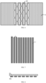
- the first heat dissipation sheet 3 includes a plurality of heat dissipation bars 31 arranged in parallel, and there is an interval between any two adjacent heat dissipation bars 31, and the interval forms the through structure in the first heat dissipation sheet 3.
- the adjacent heat dissipation bars 31 may be folded relative to each other due to the interval, so that the entire first heat dissipation sheet 3 is bendable as a whole.
- the first heat dissipation sheet 3 of this structure has a better bending effect, and may further reduce the stress influence of metal parts on the flexible display module, and the display panel has higher flexibility and reliability.
- the overall resilience of the first heat dissipation sheet 3 may be further reduced, and the difficulty of assembling the complete flexible device and the difficulty of implementing flexible action may be reduced.
- the heat dissipation bar 31 and the interval thereof are at least arranged in the bendable area of the first heat dissipation sheet 3.
- the structure of the heat dissipation bar may also be provided in the non-bend area to dissipate the heat of the flexible battery or to support the display panel.
- the arrangement direction of the heat dissipation bars 31 may be consistent with the bending direction to achieve bending. It should be noted that the parallel arrangement of the multiple heat dissipation bars described in the present disclosure allows the angle error of the actual product due to process accuracy and other reasons.
- the heat dissipation bar 31 may be adhered to a base layer 37, and then the base layer 37 is adhered to the flexible display panel or the flexible battery.
- the base layer 37 may also be fixed on the flexible battery or flexible display panel by mechanical connection, such as clamping, riveting.
- the heat dissipation bar 31 may be displaced in the bending direction (i.e., the width direction) during a plurality of bending processes, resulting in uniform heat conduction and reduced supporting capacity of the first heat dissipation sheet.
- At least one first protruding portion 301 is provided on at least one long side of the heat dissipation bar 31 to face an adjacent heat dissipation bar 31.
- the first protruding portion 301 may abut on the adjacent heat dissipation bar 31 to limit the position of the heat dissipation bar 31 itself or the adjacent heat dissipation bar 31 thereto, so that a fixed interval is always maintained between the two adjacent heat dissipation bars 31 to avoid reduction in the heat conduction uniformity and the supporting capacity due to a large displacement.
- the first protruding portion 301 may be provided on only one long side of the heat dissipation bar 31 or may be provided on two long sides of the heat dissipation bar 31.
- Each heat dissipation bar 31 may be provided with one or more first protruding portions 301.
- the positions of the first protruding portions 301 on two adjacent heat dissipation bars 31 may or may not correspond to each other.
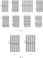
- a plurality of heat dissipation bars 31 are arranged to be spaced apart from each other horizontally, and the right side of each heat dissipation bar 31 is provided with one first protruding portion 301 protruding to the right, and respective first protruding portions 301 are located on the same horizontal line.
- the right side of each heat dissipation bar 31 is provided with two first protruding portions 301 which are at upper and lower positions respectively and protrude to the right, the respective upper first protruding portions 301 are located on the same horizontal line, and the lower first protruding portions 301 are located on the same horizontal line.
- each heat dissipation bar 31 is provided with one first protruding portion 301 protruding to the left, and the right side of each heat dissipation bar 31 is provided with one first protruding portion 301 protruding to the right, and the respective first protruding portions 301 are located on the same horizontal line. Therefore, the first protruding portions 301 of two adjacent heat dissipation bars 31 are arranged oppositely. As shown in FIG.
- each of the left and right sides of each heat dissipation bar 31 is provided with two first protruding portions 301 which are at upper and lower positions respectively, the respective upper first protruding portions 301 are located on the same horizontal line, and the respective lower first protruding portions 301 are located on the same horizontal line. As shown in FIG.
- each heat dissipation bar 31 is provided with one first protruding portion 301 protruding to the left
- the right side of each heat dissipation bar 31 is provided with one first protruding portion 301 protruding to the right
- the respective first protruding portions 301 protruding to the left are arranged on one horizontal line
- the respective first protruding portions 301 protruding to the right are arranged on another horizontal line. Therefore, the first protruding portions 301 of two adjacent heat dissipation bars 31 are staggered up and down. As shown in FIG.
- each of the left and right sides of each heat dissipation bar 31 is provided with two first protruding portions 301 which are at upper and lower positions respectively, and each heat dissipation bar 31 has four first protruding portions 301 that are staggered left and right.
- each of the left and right sides of each heat dissipation bar 31 is provided with three first protruding portions 301 which are at upper, middle and lower positions respectively, and the first protruding portions 301 of each heat dissipation bar 31 are arranged at three horizontal lines respectively.
- a plurality of heat dissipation bars 31 may be arranged in a plurality of groups in the longitudinal direction in the figure.
- the shapes of the first protruding portions 301 in the above specific embodiments are all semicircular as an example. It can be understood that the shape of the first protruding portion 301 may also be of any other shape, such as rectangle shown in FIG. 10 (a) , trapezoid shown in FIG. 10 (b) .
- the long side of the heat dissipation bar 31 is further provided with a second protruding portion 302 at a position corresponding to the first protruding portion 301 of the adjacent heat dissipation bar 31.
- the second protruding portion 302 is provided with a notch 3021, and the notch 3021 matches the shape of the first protruding portion 301, so that when the two heat dissipation bars 31 are displaced, the notch 3021 and the first protruding portion 301 may be engaged to prevent the heat dissipation bars 31 from moving further.
- the notch 3021 may enclose the first protruding portion 301, which may also prevent the heat dissipation bar 31 from moving in the longitudinal direction in the figure, that is, may limit the position of the heat dissipation bar 31 in both the horizontal and vertical directions, and may have a better position limitation effect.
- the shapes of the first protruding portion 301 and the notch 3021 are both trapezoidal.
- the shapes of the first protruding portion 301 and the notch 3021 are both semi-elliptical.
- the shape of the second protruding portion 302 includes but is not limited to the rectangular protruding portion shown in the figure, and may also be other shapes.
- each heat dissipation bar may also be provided with a plurality of such structures. As shown in FIG. 11(c) , each heat dissipation bar is provided with three first protruding portions 301 and second protruding portions 302.
- the first heat dissipation sheet 3 is further provided with a heat dissipation pipe 36, which is used to connect the heat dissipation bars 31 together to conduct the heat of the respective heat dissipation bars 31, thereby improving the uniformity of heat conduction of the entire first heat dissipation sheet 3, and making the heat distribution on the entire first heat dissipation sheet 3 more uniform.
- the adjacent heat dissipation bars 31 may be connected together by a connection member 33.
- the connection member 33 and the heat dissipation bar 31 may be pivotally connected, which structure may allow two adjacent heat dissipation bars 31 to be folded relatively.
- the connection member 33 may be a bar-shaped rod provided at ends of two adjacent heat dissipation bars 31. The extending direction of the bar-shaped rod is perpendicular to the extending direction of the heat dissipation bar 31.
- connection member 3 may also be a rotation shaft 35 arranged in parallel with the heat dissipation bar 31.
- the rotation shaft 35 is arranged between two adjacent heat dissipation bars 31.
- connection member 33 may also have other structures, for example, it may also be a connection wire that passes through the through holes of respective heat dissipation bars to connect the heat dissipation bars in series, which will not be listed here. In this structure, even if the interval between two adjacent heat dissipation bars 31 is small, the first heat dissipation sheet 3 can still be bent through the pivot connection structure.
- connection member 33 Since the heat dissipation bars 31 are connected as a whole by the connection member 33, the structure thereof is more stable.
- the material of the connection member is preferably a metal or other material with a heat-conducting function, so that the heat on the heat dissipation bars 31 can be transferred to each other through the connection member, so that the heat distribution of the entire first heat dissipation sheet 3 is more uniform.
- the width and interval of the heat dissipation bars 31 have a significant impact on the bending effect, heat dissipation effect, and support effect. If the interval is too large, the width of the heat dissipation bar 31 is too narrow, which will lead to poor heat dissipation and poor support. If the interval is too small, the width of the heat dissipation bar 31 is too wide, which may affect the bending effect.
- the width L of the heat dissipation bar 31 satisfies 0.05mm ⁇ L ⁇ 20mm.
- L may take values of 0.05nm, 0.1nm, 1nm, 2nm, 5nm, 10nm, 15nm, 20nm.
- the width h of the interval between two adjacent heat dissipation bars 31 satisfies 0.1mm ⁇ h ⁇ 10mm.
- h can take values of 0.1nm, 1nm, 2nm, 5nm, 8nm, and 10nm. Within this size range, the bending effect of the first heat dissipation sheet is smoother, the heat dissipation effect is ideal, and the structural stability and support effect is better.
- the width L of the heat dissipation bar 31 is the width of the portion of the heat dissipation bar 31 other than the first protruding portion 301, that is, the minimum width of the heat dissipation bar 31.
- the width h of the interval between two adjacent heat dissipation bars 31 is the distance between the parts of the two heat dissipation bars 31 other than the first protruding portions 301, that is, the maximum distance between two adjacent heat dissipation bars 31.
- the size of the first protruding portion 301 may be set according to the structure and the distance between the heat dissipation bars 31.
- the heat dissipation bar 31 is also provided with a through hole 32.
- the through hole 32 makes the heat dissipation bar 31 bendable, thereby further improving the bendable performance of the first heat dissipation sheet.
- the thickness of the first heat dissipation sheet is preferably no more than 1mm. Such thickness may meet the heat dissipation requirements, and at the same time, the thickness of the entire device is not significantly increased, which is conducive to achieving a lighter and thinner configuration.
- the first heat dissipation sheet 3 may include a non-bending area 30, and the non-bending area 30 may be a whole non-bendable structural layer.
- the area of the first heat dissipation sheet 3 corresponding to the non-bendable motherboard IC of the display panel may be set as a whole metal layer, and the other bendable area is a heat dissipation sheet structure.
- first heat dissipation sheet 3 in the heat dissipation assembly shown in FIG. 3 has been described in detail above.
- the first heat dissipation sheet 3 may also be arranged on the side of the flexible battery 2 facing away from the flexible display panel 1 to absorb heat emitted from the side of the flexible battery 2 facing away from the display panel 1, which can also reduce the temperature of the battery 2 to prevent the local temperature of the battery 2 from being too high.
- the heat dissipation assembly further includes a heat insulation layer 4, and the first heat dissipation sheet 3 and the heat insulation layer 4 are both provided between the flexible display panel 1 and the flexible battery 2.
- the heat insulation layer 4 is located between the first heat dissipation sheet 3 and the flexible display panel 1.
- the heat insulation layer 4 is in the shape of sheet as a whole, and also has a bendable area.
- the function of the heat insulation layer 4 is to isolate the heat between the first heat dissipation sheet 3 and the flexible display panel 1 to shield the thermal effect of the high temperature of the first heat dissipation sheet 3 on the flexible display panel 1. Therefore, the heat insulation layer 4 may be made of materials with lower thermal conductivity, for example, organic materials such as rubber. At the same time, the heat insulation layer 4 may also have a bendable area so that it may also be bent or folded to match the overall structure of the display device. It can be understood that the bendable area of the heat insulation layer 4 may correspond to the bendable area of the first heat dissipation sheet 3, the flexible display panel 1 or the flexible battery 2.
- a structure of a patterned opening hole 10 may also be provided on the heat insulation layer 4, or a material with higher flexibility may be selected.
- the heat insulation layer 4 may further use an insulating material to prevent the current leaked from the battery 2 from being conducted to the display panel 1 via the first heat dissipation sheet 3 and affecting the display panel 1.
- the material of the heat insulation layer 4 is preferably rubber, silica gel, polyurethane, acrylic or porous materials such as foam materials, fiber materials.
- the hollow structure of the porous materials may be filled with air or other media.
- the material of the heat insulation layer 4 may also be heat-reflective materials, such as gold-plated, silver-plated polyimide film.
- the heat insulation layer 4 may be fixed to the first heat dissipation sheet 3 or the display panel 1 through a mechanical connection method or an adhesive method.
- the heat dissipation assembly further includes a second heat dissipation sheet 5.
- the first heat dissipation sheet 3 and the heat insulation layer 4 are both provided between the flexible display panel 1 and the flexible battery 2
- the heat insulation layer 4 is arranged between the first heat dissipation sheet 3 and the flexible display panel 1
- the second heat dissipation sheet 5 is arranged on the side of the flexible battery 2 away from the flexible display panel 1, and have a sheet shape as a whole to cover the side of the flexible batter 2 to absorb the heat emitted by the side of the flexible battery 2 away from the display panel 1, so that the entire device has a more ideal heat dissipation performance.
- the second heat dissipation sheet 5 has a bendable area. It can be understood that the bendable area of the second heat dissipation sheet 5 corresponds to the bendable areas of the first heat dissipation sheet 3, the heat insulation layer 4, the flexible battery 2, and the flexible display panel 1. In other embodiments, when the first heat dissipation sheet 3 is arranged on the side of the flexible battery 2 away from the flexible display panel 1, the second heat dissipation sheet 5 is arranged on the side of the flexible battery 2 facing the flexible display panel 1, that is, between the flexible battery 2 and the flexible display panel 1.
- the heat insulation layer may be arranged between the second heat dissipation sheet 5 and the flexible display panel 1 to block the influence of the high temperature of the second heat dissipation sheet 5 on the flexible display panel 1.
- the heat insulation layer may always be arranged between the heat dissipation sheet close to the flexible display panel and the flexible display panel.
- the structure of the second heat dissipation sheet 5 may be the same as or different from that of the first heat dissipation sheet 3.
- the material of the second heat dissipation sheet 5 may be the same as or different from that of the first heat dissipation sheet 3.
- the first heat dissipation sheet adopts the metal heat dissipation bar structure shown in FIG. 9
- the second heat dissipation sheet adopts a one-piece graphene film layer
- the first heat dissipation sheet adopts the metal patterned through hole structure shown in FIG. 6
- the second heat dissipation sheet adopts the metal heat dissipation bar structure shown in FIG. 9 .
- the fixing method of the second heat dissipation sheet 5 and the flexible battery 2 may refer to that of the first heat dissipation sheet 3, and the structure of the bendable area of the second heat dissipation sheet 5 may also refer to that of the first heat dissipation sheet 3, which will not be repeated here.
- the parameters such as the thickness and size of the second heat dissipation sheet 5 may also be the same as or different from those of the first heat dissipation sheet 3.
- FIG. 19 shows another structure of the heat dissipation assembly in an embodiment, and the structure includes a first heat dissipation sheet 3, a heat insulation layer 4, a second heat dissipation sheet 5, and a heat conduction member 6.
- the first heat dissipation sheet 3 and the heat insulation layer 4 are both provided between the flexible display panel 1 and the flexible battery 2, the heat insulation layer 4 is arranged between the first heat dissipation sheet 3 and the flexible display panel 1, the second heat dissipation sheet 5 is arranged on the side of the flexible battery 2 away from the flexible display panel 1, the heat conduction member 6 is arranged between the first heat dissipation sheet 3 and the second heat dissipation sheet 5 and connects the first heat dissipation sheet 3 and the second heat dissipation sheet 5, the heat conduction member 6 is positioned on at least one side of the flexible battery 2 and is spaced apart from the flexible battery 2.
- the heat conduction member 6 is used to absorb the heat on the first heat dissipation sheet 3 and the second heat dissipation sheet 5. Since the heat conduction member 6 is not in contact with the flexible battery 2, it further conducts the heat on the first heat dissipation sheet 3 and the second heat dissipation sheet 5 to the heat conduction member 6 to further reduce the heat of the battery 2.
- the heat conduction member 6 may be a metal material, or an organic material with high heat conduction efficiency such as graphene.
- the heat conduction member 6 may be a columnar structure arranged between the first heat dissipation sheet 3 and the second heat dissipation sheet 5, or may also be a sheet-like structure, of course, it may also be of other forms, which is not specifically limited in the present disclosure.
- the heat conduction member 6 may be arranged on only one side of the battery 2, or on more sides of the battery 2.
- the heat conduction member 6 may be an integral structure with the first heat dissipation sheet 3 or the second heat dissipation sheet 5.
- the heat conduction member 6 may also be connected to the heat dissipation pipe 36 to conduct heat away.
- the display device further includes a heat dissipation unit 7, and the heat dissipation unit 7 is connected to at least one of the above first heat dissipation sheet, second heat dissipation sheet or heat conduction member for absorbing the heat of the heat dissipation assembly and conducting the heat to the outside of the display device.
- the heat dissipation unit 7 is disposed in the housing of the display device, and is used to conduct the absorbed heat to the outside of the housing, and may include structures such as cooling fins and fans.
- the heat dissipation unit 7 In order to be connected to the heat dissipation unit 7, at least one of the first heat dissipation sheet 3, the second heat dissipation sheet 5, and the heat conduction member 6 may extend to the heat dissipation unit 7.
- the heat dissipation unit 7 is provided on a side of the flexible battery 2, and the first dissipation sheet 3 extends outward along said side relative to the second dissipation sheet 5 until being connected to the radiating unit 7.
- the leftward arrow in the figure indicates the omitted extension.
- it may also be the second heat dissipation sheet 5 or the heat conduction member 6 that extends toward the heat dissipation unit 7, which is not specifically limited in the present disclosure.
- FIG. 19 also shows a cover plate 8 covering a light-emitting side of the display panel 1 and a flexible circuit board 9 connected to the display panel 1 in the display device.
- the display device also includes other parts such as a driver IC and a housing, which is not listed one by one herein.
- the size of the flexible battery 2 is larger than that of the flexible display panel 1. In other embodiments, the size of the flexible battery 2 may also be equal to or smaller than the flexible display panel 1.
- the present disclosure does not specifically limit the application of the display device, which may be any product or part with display function such as televisions, laptops, tablets, wearable display devices, mobile phones, car displays, navigation, e-books, digital photo frames, advertising light boxes.
Landscapes
- Engineering & Computer Science (AREA)
- Chemical Kinetics & Catalysis (AREA)
- General Chemical & Material Sciences (AREA)
- Electrochemistry (AREA)
- Chemical & Material Sciences (AREA)
- Theoretical Computer Science (AREA)
- Manufacturing & Machinery (AREA)
- Physics & Mathematics (AREA)
- Computer Hardware Design (AREA)
- General Physics & Mathematics (AREA)
- Human Computer Interaction (AREA)
- General Engineering & Computer Science (AREA)
- Life Sciences & Earth Sciences (AREA)
- Biophysics (AREA)
- Optics & Photonics (AREA)
- Devices For Indicating Variable Information By Combining Individual Elements (AREA)
- Power Engineering (AREA)
- Electroluminescent Light Sources (AREA)
- Sealing Battery Cases Or Jackets (AREA)
- Secondary Cells (AREA)
Applications Claiming Priority (3)
| Application Number | Priority Date | Filing Date | Title |
|---|---|---|---|
| CN202010450415.4A CN111564677A (zh) | 2020-05-25 | 2020-05-25 | 柔性显示装置 |
| CN202011267683.9A CN113725514B (zh) | 2020-05-25 | 2020-11-13 | 柔性显示装置 |
| PCT/CN2021/086289 WO2021238450A1 (zh) | 2020-05-25 | 2021-04-09 | 柔性显示装置 |
Publications (3)
| Publication Number | Publication Date |
|---|---|
| EP3993138A1 EP3993138A1 (en) | 2022-05-04 |
| EP3993138A4 EP3993138A4 (en) | 2022-10-12 |
| EP3993138B1 true EP3993138B1 (en) | 2023-11-08 |
Family
ID=72072379
Family Applications (1)
| Application Number | Title | Priority Date | Filing Date |
|---|---|---|---|
| EP21810268.9A Active EP3993138B1 (en) | 2020-05-25 | 2021-04-09 | Flexible display device |
Country Status (5)
| Country | Link |
|---|---|
| US (1) | US12015133B2 (https=) |
| EP (1) | EP3993138B1 (https=) |
| JP (1) | JP7748286B2 (https=) |
| CN (2) | CN111564677A (https=) |
| WO (1) | WO2021238450A1 (https=) |
Families Citing this family (15)
| Publication number | Priority date | Publication date | Assignee | Title |
|---|---|---|---|---|
| CN111564677A (zh) | 2020-05-25 | 2020-08-21 | 京东方科技集团股份有限公司 | 柔性显示装置 |
| CN112349206B (zh) * | 2020-11-09 | 2022-07-12 | 厦门天马微电子有限公司 | 一种可折叠显示装置 |
| KR102941495B1 (ko) * | 2020-11-13 | 2026-03-19 | 삼성디스플레이 주식회사 | 표시 장치 |
| CN113066361A (zh) | 2021-03-01 | 2021-07-02 | 武汉华星光电半导体显示技术有限公司 | 柔性显示装置及其制备方法 |
| US12393231B2 (en) | 2021-05-26 | 2025-08-19 | Boe Technology Group Co., Ltd. | Flexible display apparatus and support assembly |
| CN113450651B (zh) * | 2021-06-29 | 2022-10-11 | 上海天马微电子有限公司 | 柔性显示面板散热装置及其应用方法和显示装置 |
| CN113870714B (zh) * | 2021-09-29 | 2023-10-31 | 武汉华星光电半导体显示技术有限公司 | 一种折叠显示背板及显示终端 |
| KR102879428B1 (ko) * | 2021-12-13 | 2025-10-30 | 엘지디스플레이 주식회사 | 표시장치 및 그 제조방법 |
| EP4412188A4 (en) | 2021-12-16 | 2025-01-15 | Samsung Electronics Co., Ltd. | HEAT DISSIPATION STRUCTURE AND ELECTRONIC DEVICE THEREOF |
| KR20230111662A (ko) * | 2022-01-17 | 2023-07-26 | 삼성디스플레이 주식회사 | 표시 장치 및 이의 제조 방법 |
| KR102751775B1 (ko) * | 2022-02-08 | 2025-01-09 | 주식회사 아모그린텍 | 열전달부재, 이를 포함하는 열전달 어셈블리 및 전자기기 |
| CN114495725A (zh) * | 2022-03-14 | 2022-05-13 | 武汉华星光电半导体显示技术有限公司 | 一种柔性显示装置 |
| KR20230151147A (ko) | 2022-04-22 | 2023-11-01 | 삼성디스플레이 주식회사 | 표시 장치 |
| WO2024000308A1 (zh) * | 2022-06-29 | 2024-01-04 | 京东方科技集团股份有限公司 | 一种显示模组、智能终端 |
| CN119768851A (zh) * | 2022-09-08 | 2025-04-04 | 大日本印刷株式会社 | 柔性显示装置用金属支承体及其制造方法、以及柔性显示装置 |
Family Cites Families (39)
| Publication number | Priority date | Publication date | Assignee | Title |
|---|---|---|---|---|
| JP2000010661A (ja) * | 1998-06-18 | 2000-01-14 | Mitsubishi Electric Corp | 携帯型情報処理装置および携帯型情報処理装置用カバー、卓上型情報処理装置 |
| JP2002258758A (ja) * | 2001-02-28 | 2002-09-11 | Toshiba Corp | ディスプレイ機器および携帯モバイル機器 |
| CN2672860Y (zh) * | 2003-10-30 | 2005-01-19 | 技嘉科技股份有限公司 | 一种散热片模块 |
| KR20050122517A (ko) * | 2004-06-24 | 2005-12-29 | 삼성에스디아이 주식회사 | 플라즈마 표시장치 조립체 |
| US20060022910A1 (en) * | 2004-07-30 | 2006-02-02 | Takuro Sekiya | Multifunction display device |
| JP5216602B2 (ja) * | 2009-01-08 | 2013-06-19 | 株式会社日立製作所 | 画像表示装置 |
| US9176535B2 (en) * | 2011-06-03 | 2015-11-03 | Microsoft Technology Licensing, Llc | Flexible display flexure assembly |
| US8811032B2 (en) * | 2011-08-05 | 2014-08-19 | Blackberry Limited | Handheld electronic device having a flexible display |
| JP2014029918A (ja) * | 2012-07-31 | 2014-02-13 | Sharp Corp | 携帯端末 |
| KR102077140B1 (ko) * | 2013-03-18 | 2020-02-14 | 삼성디스플레이 주식회사 | 플렉시블 디스플레이 모듈 |
| JP6125972B2 (ja) * | 2013-10-30 | 2017-05-10 | 東芝ホームテクノ株式会社 | 携帯情報端末 |
| CN105098249B (zh) * | 2014-04-18 | 2018-03-13 | 比亚迪股份有限公司 | 柔性电池和具有其的柔性电池组 |
| KR101516766B1 (ko) * | 2014-09-02 | 2015-05-04 | 삼성전자주식회사 | 곡면 표시 영역을 가지는 디스플레이 및 이를 포함하는 전자 장치 |
| KR102228857B1 (ko) * | 2014-09-05 | 2021-03-17 | 엘지전자 주식회사 | 휴대 전자기기 |
| WO2016064240A1 (ko) * | 2014-10-24 | 2016-04-28 | 주식회사 아모그린텍 | 롤러블 디스플레이 장치 |
| US10185363B2 (en) * | 2014-11-28 | 2019-01-22 | Semiconductor Energy Laboratory Co., Ltd. | Electronic device |
| US10613586B2 (en) * | 2015-03-23 | 2020-04-07 | Semiconductor Energy Laboratory Co., Ltd. | Display device, electronic device, and system |
| US9882179B2 (en) * | 2015-07-29 | 2018-01-30 | Semiconductor Energy Laboratory Co., Ltd. | Secondary battery and electronic device including secondary battery |
| JP6850587B2 (ja) * | 2015-11-18 | 2021-03-31 | 株式会社半導体エネルギー研究所 | 電子機器 |
| JP6978207B2 (ja) * | 2016-02-12 | 2021-12-08 | 三洋化成工業株式会社 | リチウムイオン電池 |
| CN106229556A (zh) * | 2016-09-05 | 2016-12-14 | 南方科技大学 | 柔性电池及柔性电池的制备方法 |
| JP6890180B2 (ja) * | 2016-11-25 | 2021-06-18 | 華為技術有限公司Huawei Technologies Co.,Ltd. | 熱放散パネル、熱放散装置、及び電子デバイス |
| KR102680246B1 (ko) | 2016-11-30 | 2024-07-01 | 엘지디스플레이 주식회사 | 폴더블 디스플레이의 폴딩장치 및 이를 구비한 디스플레이 장치 |
| CN107275378B (zh) * | 2017-07-14 | 2019-09-03 | 武汉天马微电子有限公司 | 柔性显示面板 |
| US10517196B2 (en) * | 2017-09-05 | 2019-12-24 | Wuhan China Star Optoelectronics Semiconductor Display Technology Co., Ltd. | Flexible display device |
| CN107589872A (zh) * | 2017-09-20 | 2018-01-16 | 厦门天马微电子有限公司 | 一种显示面板和显示装置 |
| CN109699151B (zh) * | 2017-10-20 | 2020-02-14 | 华为技术有限公司 | 膜状散热构件、可折弯显示装置以及终端设备 |
| CN107845740B (zh) * | 2017-10-23 | 2020-04-10 | 武汉华星光电半导体显示技术有限公司 | 一种柔性基板的制备方法及柔性基板 |
| US10355228B2 (en) | 2017-10-23 | 2019-07-16 | Wuhan China Star Optoelectronics Semiconductor Display Technology Co., Ltd. | Method of manufacturing flexible substrate and flexible substrate |
| CN109727532A (zh) * | 2017-10-30 | 2019-05-07 | 京东方科技集团股份有限公司 | 柔性显示屏及显示装置 |
| KR102456889B1 (ko) * | 2017-11-01 | 2022-10-21 | 엘지전자 주식회사 | 플렉서블 프레임 및 이를 구비하는 플렉서블 디스플레이 유닛 |
| CN209861400U (zh) * | 2018-09-14 | 2019-12-27 | 深圳市柔宇科技有限公司 | 柔性显示装置 |
| CN109407196B (zh) * | 2018-09-30 | 2021-11-30 | 广州国显科技有限公司 | 偏光片、柔性显示面板及柔性显示装置 |
| CN110706593A (zh) * | 2019-09-12 | 2020-01-17 | 深圳世竟液态金属有限公司 | 支撑结构和可折叠显示装置 |
| CN110796955B (zh) * | 2019-11-13 | 2021-12-03 | 京东方科技集团股份有限公司 | 柔性显示屏和电子设备 |
| CN110767096B (zh) * | 2019-11-15 | 2021-12-03 | 京东方科技集团股份有限公司 | 支撑结构及显示装置 |
| CN111564677A (zh) | 2020-05-25 | 2020-08-21 | 京东方科技集团股份有限公司 | 柔性显示装置 |
| KR102932215B1 (ko) * | 2020-06-29 | 2026-03-03 | 엘지이노텍 주식회사 | 탄성 부재 및 이를 포함하는 디스플레이 장치 |
| CN112186233B (zh) * | 2020-10-09 | 2022-08-19 | 京东方科技集团股份有限公司 | 柔性电池及显示装置 |
-
2020
- 2020-05-25 CN CN202010450415.4A patent/CN111564677A/zh not_active Withdrawn
- 2020-11-13 CN CN202011267683.9A patent/CN113725514B/zh active Active
-
2021
- 2021-04-09 US US17/435,124 patent/US12015133B2/en active Active
- 2021-04-09 EP EP21810268.9A patent/EP3993138B1/en active Active
- 2021-04-09 JP JP2021568596A patent/JP7748286B2/ja active Active
- 2021-04-09 WO PCT/CN2021/086289 patent/WO2021238450A1/zh not_active Ceased
Also Published As
| Publication number | Publication date |
|---|---|
| CN113725514A (zh) | 2021-11-30 |
| JP7748286B2 (ja) | 2025-10-02 |
| JP2023527593A (ja) | 2023-06-30 |
| WO2021238450A1 (zh) | 2021-12-02 |
| US20220166082A1 (en) | 2022-05-26 |
| CN111564677A (zh) | 2020-08-21 |
| US12015133B2 (en) | 2024-06-18 |
| CN113725514B (zh) | 2023-08-18 |
| EP3993138A1 (en) | 2022-05-04 |
| EP3993138A4 (en) | 2022-10-12 |
Similar Documents
| Publication | Publication Date | Title |
|---|---|---|
| EP3993138B1 (en) | Flexible display device | |
| EP2685797B1 (en) | Composite material and electron device | |
| US9095077B2 (en) | Graphene heat dissipators in portable electronic devices | |
| EP3916839A1 (en) | Battery module and battery pack comprising same | |
| US11917859B2 (en) | Display module and display device | |
| CN111509158A (zh) | 电池模组、柔性显示装置及移动终端 | |
| US20230299431A1 (en) | Battery cell, battery module, and battery pack including the same | |
| CN114976377B (zh) | 电池模块及包括其的电池组 | |
| JP7497402B2 (ja) | 電子機器 | |
| KR20220014575A (ko) | 전지 팩 및 이의 제조 방법 | |
| JP2012174971A (ja) | 蓄電デバイス | |
| US20230282925A1 (en) | Battery module and battery pack including the same | |
| JP2024060763A (ja) | 電子機器 | |
| CN222465105U (zh) | 一种电子设备 | |
| JP2012160543A (ja) | 蓄電デバイス | |
| JP2012160542A (ja) | 蓄電デバイス | |
| US12581606B2 (en) | Electronic apparatus | |
| CN111312070B (zh) | 一种显示装置 | |
| CN116937209B (zh) | 一种电子设备 | |
| US20220294031A1 (en) | Metal-shell battery and electronic device | |
| CN215577411U (zh) | 显示模组和显示装置 | |
| US20240420869A1 (en) | Electronic apparatus | |
| US20250279501A1 (en) | Battery pack | |
| WO2025138018A9 (zh) | 电子设备 | |
| EP4734226A1 (en) | Battery-cell heat dissipation structure and energy storage system |
Legal Events
| Date | Code | Title | Description |
|---|---|---|---|
| STAA | Information on the status of an ep patent application or granted ep patent |
Free format text: STATUS: UNKNOWN |
|
| STAA | Information on the status of an ep patent application or granted ep patent |
Free format text: STATUS: THE INTERNATIONAL PUBLICATION HAS BEEN MADE |
|
| PUAI | Public reference made under article 153(3) epc to a published international application that has entered the european phase |
Free format text: ORIGINAL CODE: 0009012 |
|
| STAA | Information on the status of an ep patent application or granted ep patent |
Free format text: STATUS: REQUEST FOR EXAMINATION WAS MADE |
|
| 17P | Request for examination filed |
Effective date: 20211130 |
|
| AK | Designated contracting states |
Kind code of ref document: A1 Designated state(s): AL AT BE BG CH CY CZ DE DK EE ES FI FR GB GR HR HU IE IS IT LI LT LU LV MC MK MT NL NO PL PT RO RS SE SI SK SM TR |
|
| A4 | Supplementary search report drawn up and despatched |
Effective date: 20220913 |
|
| RIC1 | Information provided on ipc code assigned before grant |
Ipc: H01L 51/52 20060101ALI20220907BHEP Ipc: G06F 1/20 20060101ALI20220907BHEP Ipc: G06F 1/16 20060101ALI20220907BHEP Ipc: G09F 9/30 20060101ALI20220907BHEP Ipc: H01M 10/62 20140101ALI20220907BHEP Ipc: H01M 10/613 20140101AFI20220907BHEP |
|
| GRAP | Despatch of communication of intention to grant a patent |
Free format text: ORIGINAL CODE: EPIDOSNIGR1 |
|
| STAA | Information on the status of an ep patent application or granted ep patent |
Free format text: STATUS: GRANT OF PATENT IS INTENDED |
|
| RIC1 | Information provided on ipc code assigned before grant |
Ipc: H10K 102/00 20230101ALI20230621BHEP Ipc: H10K 50/87 20230101ALI20230621BHEP Ipc: H01M 50/136 20210101ALI20230621BHEP Ipc: H01M 50/105 20210101ALI20230621BHEP Ipc: H01M 10/6551 20140101ALI20230621BHEP Ipc: H01M 10/647 20140101ALI20230621BHEP Ipc: H01M 10/623 20140101ALI20230621BHEP Ipc: H01M 10/62 20140101ALI20230621BHEP Ipc: G09F 9/30 20060101ALI20230621BHEP Ipc: G06F 1/16 20060101ALI20230621BHEP Ipc: G06F 1/20 20060101ALI20230621BHEP Ipc: H01M 10/613 20140101AFI20230621BHEP |
|
| DAV | Request for validation of the european patent (deleted) | ||
| DAX | Request for extension of the european patent (deleted) | ||
| INTG | Intention to grant announced |
Effective date: 20230712 |
|
| GRAS | Grant fee paid |
Free format text: ORIGINAL CODE: EPIDOSNIGR3 |
|
| GRAA | (expected) grant |
Free format text: ORIGINAL CODE: 0009210 |
|
| STAA | Information on the status of an ep patent application or granted ep patent |
Free format text: STATUS: THE PATENT HAS BEEN GRANTED |
|
| AK | Designated contracting states |
Kind code of ref document: B1 Designated state(s): AL AT BE BG CH CY CZ DE DK EE ES FI FR GB GR HR HU IE IS IT LI LT LU LV MC MK MT NL NO PL PT RO RS SE SI SK SM TR |
|
| REG | Reference to a national code |
Ref country code: GB Ref legal event code: FG4D |
|
| REG | Reference to a national code |
Ref country code: CH Ref legal event code: EP |
|
| REG | Reference to a national code |
Ref country code: DE Ref legal event code: R096 Ref document number: 602021006704 Country of ref document: DE |
|
| REG | Reference to a national code |
Ref country code: IE Ref legal event code: FG4D |
|
| REG | Reference to a national code |
Ref country code: LT Ref legal event code: MG9D |
|
| REG | Reference to a national code |
Ref country code: NL Ref legal event code: MP Effective date: 20231108 |
|
| PG25 | Lapsed in a contracting state [announced via postgrant information from national office to epo] |
Ref country code: GR Free format text: LAPSE BECAUSE OF FAILURE TO SUBMIT A TRANSLATION OF THE DESCRIPTION OR TO PAY THE FEE WITHIN THE PRESCRIBED TIME-LIMIT Effective date: 20240209 |
|
| PG25 | Lapsed in a contracting state [announced via postgrant information from national office to epo] |
Ref country code: IS Free format text: LAPSE BECAUSE OF FAILURE TO SUBMIT A TRANSLATION OF THE DESCRIPTION OR TO PAY THE FEE WITHIN THE PRESCRIBED TIME-LIMIT Effective date: 20240308 |
|
| PG25 | Lapsed in a contracting state [announced via postgrant information from national office to epo] |
Ref country code: LT Free format text: LAPSE BECAUSE OF FAILURE TO SUBMIT A TRANSLATION OF THE DESCRIPTION OR TO PAY THE FEE WITHIN THE PRESCRIBED TIME-LIMIT Effective date: 20231108 |
|
| REG | Reference to a national code |
Ref country code: AT Ref legal event code: MK05 Ref document number: 1630475 Country of ref document: AT Kind code of ref document: T Effective date: 20231108 |
|
| PG25 | Lapsed in a contracting state [announced via postgrant information from national office to epo] |
Ref country code: NL Free format text: LAPSE BECAUSE OF FAILURE TO SUBMIT A TRANSLATION OF THE DESCRIPTION OR TO PAY THE FEE WITHIN THE PRESCRIBED TIME-LIMIT Effective date: 20231108 |
|
| PG25 | Lapsed in a contracting state [announced via postgrant information from national office to epo] |
Ref country code: AT Free format text: LAPSE BECAUSE OF FAILURE TO SUBMIT A TRANSLATION OF THE DESCRIPTION OR TO PAY THE FEE WITHIN THE PRESCRIBED TIME-LIMIT Effective date: 20231108 |
|
| PG25 | Lapsed in a contracting state [announced via postgrant information from national office to epo] |
Ref country code: ES Free format text: LAPSE BECAUSE OF FAILURE TO SUBMIT A TRANSLATION OF THE DESCRIPTION OR TO PAY THE FEE WITHIN THE PRESCRIBED TIME-LIMIT Effective date: 20231108 |
|
| PG25 | Lapsed in a contracting state [announced via postgrant information from national office to epo] |
Ref country code: NL Free format text: LAPSE BECAUSE OF FAILURE TO SUBMIT A TRANSLATION OF THE DESCRIPTION OR TO PAY THE FEE WITHIN THE PRESCRIBED TIME-LIMIT Effective date: 20231108 Ref country code: LT Free format text: LAPSE BECAUSE OF FAILURE TO SUBMIT A TRANSLATION OF THE DESCRIPTION OR TO PAY THE FEE WITHIN THE PRESCRIBED TIME-LIMIT Effective date: 20231108 Ref country code: IS Free format text: LAPSE BECAUSE OF FAILURE TO SUBMIT A TRANSLATION OF THE DESCRIPTION OR TO PAY THE FEE WITHIN THE PRESCRIBED TIME-LIMIT Effective date: 20240308 Ref country code: GR Free format text: LAPSE BECAUSE OF FAILURE TO SUBMIT A TRANSLATION OF THE DESCRIPTION OR TO PAY THE FEE WITHIN THE PRESCRIBED TIME-LIMIT Effective date: 20240209 Ref country code: ES Free format text: LAPSE BECAUSE OF FAILURE TO SUBMIT A TRANSLATION OF THE DESCRIPTION OR TO PAY THE FEE WITHIN THE PRESCRIBED TIME-LIMIT Effective date: 20231108 Ref country code: BG Free format text: LAPSE BECAUSE OF FAILURE TO SUBMIT A TRANSLATION OF THE DESCRIPTION OR TO PAY THE FEE WITHIN THE PRESCRIBED TIME-LIMIT Effective date: 20240208 Ref country code: AT Free format text: LAPSE BECAUSE OF FAILURE TO SUBMIT A TRANSLATION OF THE DESCRIPTION OR TO PAY THE FEE WITHIN THE PRESCRIBED TIME-LIMIT Effective date: 20231108 Ref country code: PT Free format text: LAPSE BECAUSE OF FAILURE TO SUBMIT A TRANSLATION OF THE DESCRIPTION OR TO PAY THE FEE WITHIN THE PRESCRIBED TIME-LIMIT Effective date: 20240308 |
|
| PG25 | Lapsed in a contracting state [announced via postgrant information from national office to epo] |
Ref country code: SE Free format text: LAPSE BECAUSE OF FAILURE TO SUBMIT A TRANSLATION OF THE DESCRIPTION OR TO PAY THE FEE WITHIN THE PRESCRIBED TIME-LIMIT Effective date: 20231108 Ref country code: RS Free format text: LAPSE BECAUSE OF FAILURE TO SUBMIT A TRANSLATION OF THE DESCRIPTION OR TO PAY THE FEE WITHIN THE PRESCRIBED TIME-LIMIT Effective date: 20231108 Ref country code: PL Free format text: LAPSE BECAUSE OF FAILURE TO SUBMIT A TRANSLATION OF THE DESCRIPTION OR TO PAY THE FEE WITHIN THE PRESCRIBED TIME-LIMIT Effective date: 20231108 Ref country code: NO Free format text: LAPSE BECAUSE OF FAILURE TO SUBMIT A TRANSLATION OF THE DESCRIPTION OR TO PAY THE FEE WITHIN THE PRESCRIBED TIME-LIMIT Effective date: 20240208 Ref country code: LV Free format text: LAPSE BECAUSE OF FAILURE TO SUBMIT A TRANSLATION OF THE DESCRIPTION OR TO PAY THE FEE WITHIN THE PRESCRIBED TIME-LIMIT Effective date: 20231108 Ref country code: HR Free format text: LAPSE BECAUSE OF FAILURE TO SUBMIT A TRANSLATION OF THE DESCRIPTION OR TO PAY THE FEE WITHIN THE PRESCRIBED TIME-LIMIT Effective date: 20231108 |
|
| PG25 | Lapsed in a contracting state [announced via postgrant information from national office to epo] |
Ref country code: DK Free format text: LAPSE BECAUSE OF FAILURE TO SUBMIT A TRANSLATION OF THE DESCRIPTION OR TO PAY THE FEE WITHIN THE PRESCRIBED TIME-LIMIT Effective date: 20231108 |
|
| PG25 | Lapsed in a contracting state [announced via postgrant information from national office to epo] |
Ref country code: CZ Free format text: LAPSE BECAUSE OF FAILURE TO SUBMIT A TRANSLATION OF THE DESCRIPTION OR TO PAY THE FEE WITHIN THE PRESCRIBED TIME-LIMIT Effective date: 20231108 |
|
| PG25 | Lapsed in a contracting state [announced via postgrant information from national office to epo] |
Ref country code: SK Free format text: LAPSE BECAUSE OF FAILURE TO SUBMIT A TRANSLATION OF THE DESCRIPTION OR TO PAY THE FEE WITHIN THE PRESCRIBED TIME-LIMIT Effective date: 20231108 |
|
| PG25 | Lapsed in a contracting state [announced via postgrant information from national office to epo] |
Ref country code: SM Free format text: LAPSE BECAUSE OF FAILURE TO SUBMIT A TRANSLATION OF THE DESCRIPTION OR TO PAY THE FEE WITHIN THE PRESCRIBED TIME-LIMIT Effective date: 20231108 Ref country code: SK Free format text: LAPSE BECAUSE OF FAILURE TO SUBMIT A TRANSLATION OF THE DESCRIPTION OR TO PAY THE FEE WITHIN THE PRESCRIBED TIME-LIMIT Effective date: 20231108 Ref country code: RO Free format text: LAPSE BECAUSE OF FAILURE TO SUBMIT A TRANSLATION OF THE DESCRIPTION OR TO PAY THE FEE WITHIN THE PRESCRIBED TIME-LIMIT Effective date: 20231108 Ref country code: IT Free format text: LAPSE BECAUSE OF FAILURE TO SUBMIT A TRANSLATION OF THE DESCRIPTION OR TO PAY THE FEE WITHIN THE PRESCRIBED TIME-LIMIT Effective date: 20231108 Ref country code: EE Free format text: LAPSE BECAUSE OF FAILURE TO SUBMIT A TRANSLATION OF THE DESCRIPTION OR TO PAY THE FEE WITHIN THE PRESCRIBED TIME-LIMIT Effective date: 20231108 Ref country code: DK Free format text: LAPSE BECAUSE OF FAILURE TO SUBMIT A TRANSLATION OF THE DESCRIPTION OR TO PAY THE FEE WITHIN THE PRESCRIBED TIME-LIMIT Effective date: 20231108 Ref country code: CZ Free format text: LAPSE BECAUSE OF FAILURE TO SUBMIT A TRANSLATION OF THE DESCRIPTION OR TO PAY THE FEE WITHIN THE PRESCRIBED TIME-LIMIT Effective date: 20231108 |
|
| REG | Reference to a national code |
Ref country code: DE Ref legal event code: R097 Ref document number: 602021006704 Country of ref document: DE |
|
| PLBE | No opposition filed within time limit |
Free format text: ORIGINAL CODE: 0009261 |
|
| STAA | Information on the status of an ep patent application or granted ep patent |
Free format text: STATUS: NO OPPOSITION FILED WITHIN TIME LIMIT |
|
| 26N | No opposition filed |
Effective date: 20240809 |
|
| PG25 | Lapsed in a contracting state [announced via postgrant information from national office to epo] |
Ref country code: SI Free format text: LAPSE BECAUSE OF FAILURE TO SUBMIT A TRANSLATION OF THE DESCRIPTION OR TO PAY THE FEE WITHIN THE PRESCRIBED TIME-LIMIT Effective date: 20231108 |
|
| PG25 | Lapsed in a contracting state [announced via postgrant information from national office to epo] |
Ref country code: SI Free format text: LAPSE BECAUSE OF FAILURE TO SUBMIT A TRANSLATION OF THE DESCRIPTION OR TO PAY THE FEE WITHIN THE PRESCRIBED TIME-LIMIT Effective date: 20231108 |
|
| PG25 | Lapsed in a contracting state [announced via postgrant information from national office to epo] |
Ref country code: MC Free format text: LAPSE BECAUSE OF FAILURE TO SUBMIT A TRANSLATION OF THE DESCRIPTION OR TO PAY THE FEE WITHIN THE PRESCRIBED TIME-LIMIT Effective date: 20231108 |
|
| PG25 | Lapsed in a contracting state [announced via postgrant information from national office to epo] |
Ref country code: MC Free format text: LAPSE BECAUSE OF FAILURE TO SUBMIT A TRANSLATION OF THE DESCRIPTION OR TO PAY THE FEE WITHIN THE PRESCRIBED TIME-LIMIT Effective date: 20231108 |
|
| REG | Reference to a national code |
Ref country code: CH Ref legal event code: PL |
|
| PG25 | Lapsed in a contracting state [announced via postgrant information from national office to epo] |
Ref country code: LU Free format text: LAPSE BECAUSE OF NON-PAYMENT OF DUE FEES Effective date: 20240409 |
|
| REG | Reference to a national code |
Ref country code: BE Ref legal event code: MM Effective date: 20240430 |
|
| PG25 | Lapsed in a contracting state [announced via postgrant information from national office to epo] |
Ref country code: LU Free format text: LAPSE BECAUSE OF NON-PAYMENT OF DUE FEES Effective date: 20240409 |
|
| PG25 | Lapsed in a contracting state [announced via postgrant information from national office to epo] |
Ref country code: BE Free format text: LAPSE BECAUSE OF NON-PAYMENT OF DUE FEES Effective date: 20240430 |
|
| PG25 | Lapsed in a contracting state [announced via postgrant information from national office to epo] |
Ref country code: BE Free format text: LAPSE BECAUSE OF NON-PAYMENT OF DUE FEES Effective date: 20240430 Ref country code: CH Free format text: LAPSE BECAUSE OF NON-PAYMENT OF DUE FEES Effective date: 20240430 |
|
| PG25 | Lapsed in a contracting state [announced via postgrant information from national office to epo] |
Ref country code: IE Free format text: LAPSE BECAUSE OF NON-PAYMENT OF DUE FEES Effective date: 20240409 |
|
| PGFP | Annual fee paid to national office [announced via postgrant information from national office to epo] |
Ref country code: DE Payment date: 20250417 Year of fee payment: 5 |
|
| PGFP | Annual fee paid to national office [announced via postgrant information from national office to epo] |
Ref country code: FR Payment date: 20250416 Year of fee payment: 5 |
|
| PG25 | Lapsed in a contracting state [announced via postgrant information from national office to epo] |
Ref country code: CY Free format text: LAPSE BECAUSE OF FAILURE TO SUBMIT A TRANSLATION OF THE DESCRIPTION OR TO PAY THE FEE WITHIN THE PRESCRIBED TIME-LIMIT; INVALID AB INITIO Effective date: 20210409 |
|
| PG25 | Lapsed in a contracting state [announced via postgrant information from national office to epo] |
Ref country code: HU Free format text: LAPSE BECAUSE OF FAILURE TO SUBMIT A TRANSLATION OF THE DESCRIPTION OR TO PAY THE FEE WITHIN THE PRESCRIBED TIME-LIMIT; INVALID AB INITIO Effective date: 20210409 |
|
| PG25 | Lapsed in a contracting state [announced via postgrant information from national office to epo] |
Ref country code: FI Free format text: LAPSE BECAUSE OF FAILURE TO SUBMIT A TRANSLATION OF THE DESCRIPTION OR TO PAY THE FEE WITHIN THE PRESCRIBED TIME-LIMIT Effective date: 20231108 |
|
| PGFP | Annual fee paid to national office [announced via postgrant information from national office to epo] |
Ref country code: GB Payment date: 20260323 Year of fee payment: 6 |