EP3916839A1 - Battery module and battery pack comprising same - Google Patents
Battery module and battery pack comprising same Download PDFInfo
- Publication number
- EP3916839A1 EP3916839A1 EP20826721.1A EP20826721A EP3916839A1 EP 3916839 A1 EP3916839 A1 EP 3916839A1 EP 20826721 A EP20826721 A EP 20826721A EP 3916839 A1 EP3916839 A1 EP 3916839A1
- Authority
- EP
- European Patent Office
- Prior art keywords
- stacked body
- battery
- battery cell
- cell stacked
- battery module
- Prior art date
- Legal status (The legal status is an assumption and is not a legal conclusion. Google has not performed a legal analysis and makes no representation as to the accuracy of the status listed.)
- Pending
Links
- 230000006835 compression Effects 0.000 claims description 13
- 238000007906 compression Methods 0.000 claims description 13
- 239000002390 adhesive tape Substances 0.000 claims description 6
- 238000003475 lamination Methods 0.000 claims description 2
- 239000010410 layer Substances 0.000 description 11
- 239000012790 adhesive layer Substances 0.000 description 10
- 238000000034 method Methods 0.000 description 8
- 239000011347 resin Substances 0.000 description 8
- 229920005989 resin Polymers 0.000 description 8
- 230000000052 comparative effect Effects 0.000 description 7
- 238000001816 cooling Methods 0.000 description 4
- 230000008569 process Effects 0.000 description 4
- 238000007789 sealing Methods 0.000 description 3
- 238000003466 welding Methods 0.000 description 3
- XEEYBQQBJWHFJM-UHFFFAOYSA-N Iron Chemical compound [Fe] XEEYBQQBJWHFJM-UHFFFAOYSA-N 0.000 description 2
- PXHVJJICTQNCMI-UHFFFAOYSA-N Nickel Chemical compound [Ni] PXHVJJICTQNCMI-UHFFFAOYSA-N 0.000 description 2
- 239000000853 adhesive Substances 0.000 description 2
- 230000001070 adhesive effect Effects 0.000 description 2
- 230000008859 change Effects 0.000 description 2
- 238000010030 laminating Methods 0.000 description 2
- 230000009467 reduction Effects 0.000 description 2
- VYZAMTAEIAYCRO-UHFFFAOYSA-N Chromium Chemical compound [Cr] VYZAMTAEIAYCRO-UHFFFAOYSA-N 0.000 description 1
- RYGMFSIKBFXOCR-UHFFFAOYSA-N Copper Chemical compound [Cu] RYGMFSIKBFXOCR-UHFFFAOYSA-N 0.000 description 1
- 239000004677 Nylon Substances 0.000 description 1
- 229920005830 Polyurethane Foam Polymers 0.000 description 1
- 230000008901 benefit Effects 0.000 description 1
- 239000006227 byproduct Substances 0.000 description 1
- 238000006243 chemical reaction Methods 0.000 description 1
- 229910052804 chromium Inorganic materials 0.000 description 1
- 239000011651 chromium Substances 0.000 description 1
- 229910017052 cobalt Inorganic materials 0.000 description 1
- 239000010941 cobalt Substances 0.000 description 1
- GUTLYIVDDKVIGB-UHFFFAOYSA-N cobalt atom Chemical compound [Co] GUTLYIVDDKVIGB-UHFFFAOYSA-N 0.000 description 1
- 239000000470 constituent Substances 0.000 description 1
- 229910052802 copper Inorganic materials 0.000 description 1
- 239000010949 copper Substances 0.000 description 1
- 238000005520 cutting process Methods 0.000 description 1
- 230000007547 defect Effects 0.000 description 1
- 230000000694 effects Effects 0.000 description 1
- 230000007717 exclusion Effects 0.000 description 1
- 239000002803 fossil fuel Substances 0.000 description 1
- 239000000446 fuel Substances 0.000 description 1
- 230000004927 fusion Effects 0.000 description 1
- 238000003780 insertion Methods 0.000 description 1
- 230000037431 insertion Effects 0.000 description 1
- 230000010354 integration Effects 0.000 description 1
- 229910052742 iron Inorganic materials 0.000 description 1
- WPBNNNQJVZRUHP-UHFFFAOYSA-L manganese(2+);methyl n-[[2-(methoxycarbonylcarbamothioylamino)phenyl]carbamothioyl]carbamate;n-[2-(sulfidocarbothioylamino)ethyl]carbamodithioate Chemical compound [Mn+2].[S-]C(=S)NCCNC([S-])=S.COC(=O)NC(=S)NC1=CC=CC=C1NC(=S)NC(=O)OC WPBNNNQJVZRUHP-UHFFFAOYSA-L 0.000 description 1
- 238000004519 manufacturing process Methods 0.000 description 1
- 239000012528 membrane Substances 0.000 description 1
- 229910052751 metal Inorganic materials 0.000 description 1
- 239000002184 metal Substances 0.000 description 1
- 238000012986 modification Methods 0.000 description 1
- 230000004048 modification Effects 0.000 description 1
- 229910052759 nickel Inorganic materials 0.000 description 1
- 229920001778 nylon Polymers 0.000 description 1
- 239000011496 polyurethane foam Substances 0.000 description 1
- 239000000047 product Substances 0.000 description 1
- -1 region Substances 0.000 description 1
- 239000004065 semiconductor Substances 0.000 description 1
- 238000005245 sintering Methods 0.000 description 1
- 238000003860 storage Methods 0.000 description 1
- 239000000126 substance Substances 0.000 description 1
- 239000000758 substrate Substances 0.000 description 1
Images


Classifications
-
- H—ELECTRICITY
- H01—ELECTRIC ELEMENTS
- H01M—PROCESSES OR MEANS, e.g. BATTERIES, FOR THE DIRECT CONVERSION OF CHEMICAL ENERGY INTO ELECTRICAL ENERGY
- H01M50/00—Constructional details or processes of manufacture of the non-active parts of electrochemical cells other than fuel cells, e.g. hybrid cells
- H01M50/10—Primary casings; Jackets or wrappings
- H01M50/102—Primary casings; Jackets or wrappings characterised by their shape or physical structure
- H01M50/105—Pouches or flexible bags
-
- H—ELECTRICITY
- H01—ELECTRIC ELEMENTS
- H01M—PROCESSES OR MEANS, e.g. BATTERIES, FOR THE DIRECT CONVERSION OF CHEMICAL ENERGY INTO ELECTRICAL ENERGY
- H01M10/00—Secondary cells; Manufacture thereof
- H01M10/04—Construction or manufacture in general
- H01M10/0468—Compression means for stacks of electrodes and separators
-
- H—ELECTRICITY
- H01—ELECTRIC ELEMENTS
- H01M—PROCESSES OR MEANS, e.g. BATTERIES, FOR THE DIRECT CONVERSION OF CHEMICAL ENERGY INTO ELECTRICAL ENERGY
- H01M10/00—Secondary cells; Manufacture thereof
- H01M10/42—Methods or arrangements for servicing or maintenance of secondary cells or secondary half-cells
- H01M10/48—Accumulators combined with arrangements for measuring, testing or indicating the condition of cells, e.g. the level or density of the electrolyte
- H01M10/486—Accumulators combined with arrangements for measuring, testing or indicating the condition of cells, e.g. the level or density of the electrolyte for measuring temperature
-
- H—ELECTRICITY
- H01—ELECTRIC ELEMENTS
- H01M—PROCESSES OR MEANS, e.g. BATTERIES, FOR THE DIRECT CONVERSION OF CHEMICAL ENERGY INTO ELECTRICAL ENERGY
- H01M50/00—Constructional details or processes of manufacture of the non-active parts of electrochemical cells other than fuel cells, e.g. hybrid cells
- H01M50/20—Mountings; Secondary casings or frames; Racks, modules or packs; Suspension devices; Shock absorbers; Transport or carrying devices; Holders
- H01M50/204—Racks, modules or packs for multiple batteries or multiple cells
- H01M50/207—Racks, modules or packs for multiple batteries or multiple cells characterised by their shape
- H01M50/211—Racks, modules or packs for multiple batteries or multiple cells characterised by their shape adapted for pouch cells
-
- H—ELECTRICITY
- H01—ELECTRIC ELEMENTS
- H01M—PROCESSES OR MEANS, e.g. BATTERIES, FOR THE DIRECT CONVERSION OF CHEMICAL ENERGY INTO ELECTRICAL ENERGY
- H01M50/00—Constructional details or processes of manufacture of the non-active parts of electrochemical cells other than fuel cells, e.g. hybrid cells
- H01M50/20—Mountings; Secondary casings or frames; Racks, modules or packs; Suspension devices; Shock absorbers; Transport or carrying devices; Holders
- H01M50/284—Mountings; Secondary casings or frames; Racks, modules or packs; Suspension devices; Shock absorbers; Transport or carrying devices; Holders with incorporated circuit boards, e.g. printed circuit boards [PCB]
-
- H—ELECTRICITY
- H01—ELECTRIC ELEMENTS
- H01M—PROCESSES OR MEANS, e.g. BATTERIES, FOR THE DIRECT CONVERSION OF CHEMICAL ENERGY INTO ELECTRICAL ENERGY
- H01M50/00—Constructional details or processes of manufacture of the non-active parts of electrochemical cells other than fuel cells, e.g. hybrid cells
- H01M50/20—Mountings; Secondary casings or frames; Racks, modules or packs; Suspension devices; Shock absorbers; Transport or carrying devices; Holders
- H01M50/298—Mountings; Secondary casings or frames; Racks, modules or packs; Suspension devices; Shock absorbers; Transport or carrying devices; Holders characterised by the wiring of battery packs
-
- H—ELECTRICITY
- H01—ELECTRIC ELEMENTS
- H01M—PROCESSES OR MEANS, e.g. BATTERIES, FOR THE DIRECT CONVERSION OF CHEMICAL ENERGY INTO ELECTRICAL ENERGY
- H01M50/00—Constructional details or processes of manufacture of the non-active parts of electrochemical cells other than fuel cells, e.g. hybrid cells
- H01M50/50—Current conducting connections for cells or batteries
- H01M50/502—Interconnectors for connecting terminals of adjacent batteries; Interconnectors for connecting cells outside a battery casing
- H01M50/507—Interconnectors for connecting terminals of adjacent batteries; Interconnectors for connecting cells outside a battery casing comprising an arrangement of two or more busbars within a container structure, e.g. busbar modules
-
- H—ELECTRICITY
- H01—ELECTRIC ELEMENTS
- H01M—PROCESSES OR MEANS, e.g. BATTERIES, FOR THE DIRECT CONVERSION OF CHEMICAL ENERGY INTO ELECTRICAL ENERGY
- H01M50/00—Constructional details or processes of manufacture of the non-active parts of electrochemical cells other than fuel cells, e.g. hybrid cells
- H01M50/50—Current conducting connections for cells or batteries
- H01M50/569—Constructional details of current conducting connections for detecting conditions inside cells or batteries, e.g. details of voltage sensing terminals
-
- H—ELECTRICITY
- H01—ELECTRIC ELEMENTS
- H01M—PROCESSES OR MEANS, e.g. BATTERIES, FOR THE DIRECT CONVERSION OF CHEMICAL ENERGY INTO ELECTRICAL ENERGY
- H01M2220/00—Batteries for particular applications
- H01M2220/20—Batteries in motive systems, e.g. vehicle, ship, plane
-
- Y—GENERAL TAGGING OF NEW TECHNOLOGICAL DEVELOPMENTS; GENERAL TAGGING OF CROSS-SECTIONAL TECHNOLOGIES SPANNING OVER SEVERAL SECTIONS OF THE IPC; TECHNICAL SUBJECTS COVERED BY FORMER USPC CROSS-REFERENCE ART COLLECTIONS [XRACs] AND DIGESTS
- Y02—TECHNOLOGIES OR APPLICATIONS FOR MITIGATION OR ADAPTATION AGAINST CLIMATE CHANGE
- Y02E—REDUCTION OF GREENHOUSE GAS [GHG] EMISSIONS, RELATED TO ENERGY GENERATION, TRANSMISSION OR DISTRIBUTION
- Y02E60/00—Enabling technologies; Technologies with a potential or indirect contribution to GHG emissions mitigation
- Y02E60/10—Energy storage using batteries
Definitions
- the present invention relates to a battery module and a battery pack including the same, and more particularly, to a battery module with an improved space utilization rate and a battery pack including the same.
- Rechargeable batteries having high application characteristics and electrical characteristics such as high energy density according to their products are widely applied to battery vehicles, hybrid vehicles, and electric power storage devices driven by electric driving sources as well as portable devices. These rechargeable batteries are attracting attention as new energy sources for improving environmentally-friendliness and energy efficiency in that they do not generate any by-products of energy use as well as their primary merit, in which they can drastically reduce the use of fossil fuels.
- the battery module may include a frame member that receives the battery cell stacked body in an internal space with front and rear openings.
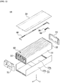
- FIG. 1 is a perspective view of a battery module having a conventional monoframe.
- a battery module may include a battery cell stacked body 12 formed by laminating a plurality of battery cells 11, a monoframe 20 of which a front surface and a rear surface are opened to cover the battery cell stacked body 12, a cover plate 40 covering the upper surface of the battery cell stacked body 12, a bus bar frame 30 covering the front surface and the rear surface of the battery cell stacked body 12, and an end plate 60 covering the front surface and the rear surface of the monoframe 20.
- Two bus bar frames 30 corresponding to each other may be connected by a cover plate 40.
- a temperature sensor 50 is attached to the cover plate 40.
- a sufficient clearance should be secured between the battery cell stacked body 12 and the monoframe 20 so that the horizontal assembly becomes stable.
- the clearance refers to a gap caused by fitting.
- a flexible printed circuit 15 is formed between the cover plate 40 and the battery cell stacked body 12 to electrically connect the bus bar frames 30 at both ends, and a cover plate 40 may prevent the flexible printed circuit 15 from being damaged during the horizontal assembly.
- the height of the battery module may also be increased by its thickness, and the weight of the battery module may be increased.
- the height of the monoframe 20 should be largely designed in consideration of the maximum height of the battery cell stacked body 12 and the assemble clearance in the insertion process, and as a result, unnecessarily wasted space may occur.
- the object to be solved by the present invention is to provide a battery module and a battery pack including the same that improve a space utilization rate by modifying the structure of a frame member surrounding the battery cell stacked body, and having a sensing connection member and a new temperature sensor attachment method with a more compact and simple structure to maximize the merit of this new structure.
- a battery module includes: a battery cell stacked body in which a plurality of battery cells are stacked; a U-shaped frame receiving the battery cell stacked body and having an opened upper part; an upper plate covering the battery cell stacked body on the opened U-shaped frame; a bus bar frame respectively formed at both ends of the battery cell stacked body; a signal connection portion disposed between the upper plate and the battery cell stacked body and connecting bus bar frames respectively formed at both ends of the battery cell stacked body; and a bridge adjacent to the signal connection portion and hinged to the bus bar frame, wherein a temperature sensor is attached to the bridge.
- the bridge may have a rotation axis.
- the battery module may further include a compression pad disposed between the bridge and the battery cell stacked body.
- the battery module may further include a double-sided adhesive tape disposed between the compression pad and the battery cell stacked body.
- the temperature sensor may be a thermistor device.
- the surface of the battery cell stacked body perpendicular to the lamination direction of the plurality of battery cells may be mounted to the bottom part of the U-shaped frame.
- the battery module may further include end plates respectively coupled to both opened sides of the U-shaped frame, and both opened sides of the U-shaped frame may face each other based on the direction in which an electrode lead of the battery cell stacked body is protruded.
- the U-shaped frame may include a bottom part and two side parts facing each other while being connected by the bottom part, and a distance between the two side parts may be the same as a width of the upper plate.
- the signal connection portion may be formed of a flexible flat cable (FFC), and may connect the bus bar frames of both ends of the battery cell stacked body.
- FFC flexible flat cable
- a battery pack according another exemplary embodiment of the present invention includes the above-described battery module.
- a space utilization rate may be improved by implementing the U-shaped frame to reduce a tolerance between the battery cell stacked body and the frame in comparison with conventional art.
- the cover plate is removed, and an assemble interference may be minimized by attaching the temperature sensor to the temperature sensor bridge, and the temperature sensor may be fixed at a constant position.
- the phrase “on a plane” means viewing a target portion from the top
- the phrase “on a cross-section” means viewing a cross-section formed by vertically cutting a target portion from the side.
- FIG. 2 is an exploded perspective view showing a battery module according to an exemplary embodiment of the present invention.
- FIG. 3 is a perspective view of a pouch-type battery according to an exemplary embodiment of the present invention.
- a battery module 100 includes a battery cell stacked body 120 including a plurality of battery cells 110, a U-shaped frame 210 of which an upper surface, a front surface, and a rear surface are opened, an upper plate 220 covering an upper part of the battery cell stacked body 120, end plates 311 and 312 respectively disposed at the front and rear of the battery cell stacked body 120, and bus bar frames 310 and 320 disposed between the battery cell stacked body 120 and the end plates 311 and 312.
- the U-shaped frame 210 is formed of a plate-shaped structure that is bent to continuously surround the front, top, and rear surfaces adjacent to each other among the other outer surfaces except for the surfaces of the battery cell stacked body 120 corresponding to the first side and the second side.
- the upper plate 220 is composed of one plate-shaped structure surrounding the bottom surface excluding the front, top, and back surfaces covered by the U-shaped frame 210 among the other outer surfaces excluding the front and rear surfaces of the battery cell stacked body 120.
- the U-shaped frame 210 includes a bottom part 300a and two side parts 300b facing each other. As the U-shaped frame 210 and the upper plate 220 are combined by welding and the like in a state that edge parts corresponding to each other are in contact, thereby forming the structure surrounding the battery cell stacked body 120. That is, the U-shaped frame 210 and the upper plate 220 may be combined by welding or the like at the corner portions corresponding to each other.
- the battery cell stacked body 120 may include a plurality of battery cells 110 stacked in one direction, and the plurality of battery cells 110 may be stacked in a Y-axis direction as shown in FIG. 2 .
- the battery cell 110 is preferably a pouch-type battery cell.
- the battery cell 110 according to the present exemplary embodiment has a structure in which two electrode leads 111 and 112 corresponding to each other are respectively protruded from one end 114a and another end 114b of a battery main body 113.
- the battery cell 110 may be manufactured by adhering both ends 114a and 114b of the battery case 114 and one side portion 114c connecting them in a state in which an electrode assembly (not shown) is received in a battery case 114.
- the battery cell 110 according to the present exemplary embodiment has a total of three sealing portions 114sa, 114sb, and 114sc, and the sealing portions 114sa, 114sb, and 114sc are sealed by a method such as heat fusion, while the remaining one side portion may be formed of a connection portion 115.
- the length direction of the battery cell 110 is defined between both ends 114a and 114b of the battery case 114, and the width direction of the battery cell 110 may be defined between the one side portion 114c connecting both ends 114a and 114b of the battery case 114 and the connection portion 115.
- connection portion 115 is an area that extends along a border of the battery cell 110, and a protruded portion 110p of the battery cell 110 may be formed at the end of the connection portion 115.
- the protruded portion 110p may be formed on at least one of both ends of the connection portion 115, and may be protruded in the direction perpendicular to the extending direction of the connection portion 115.
- the protruded portion 110p may be disposed between one of the sealing portions 114sa and 114sb of both ends 114a and 114b of the battery case 114 and the connection portion 115.
- the battery case 114 is generally composed of a laminate structure of a resin layer/a metal thin membrane layer/a resin layer.
- the battery case surface is formed of an O (oriented)-nylon layer
- an adhesion member such as a viscous adhesive of a double-sided adhesive tape or a chemical adhesive bonded by a chemical reaction upon adhesion may be attached to the surface of the battery case to form the battery cell stacked body 120.
- the battery cell stacked body 120 may be stacked in the Y-axis direction and received in a U-shaped frame 300 in the Z-axis direction, and then cooling may be performed by a thermally conductive resin layer (not shown) formed between the battery cell stacked body 120 and a bottom part 210a of the U-shaped frame 300.
- the battery cell may be formed as a cartridge-type part and then fixing between the battery cells may be performed by assembling the battery module frame. In this comparative example, due to the presence of the cartridge-type part, there is little cooling or the cooling may proceed in the direction of the surface of the battery cell, and the cooling is not good in the height direction of the battery module.
- the thermally conductive resin may be coated on the bottom part 210a of the U-shaped frame 210 and the thermally conductive resin may be cured to form the thermally conductive resin layer.
- the battery cell stacked body 120 may be mounted to the bottom part 210a of the U-shaped frame 210 while moving along the direction perpendicular to the bottom part 210a of the U-shaped frame 210.
- the thermally conductive resin layer is disposed between the bottom part 210a of the U-shaped frame 210 and the battery cell stacked body 120.
- the thermal conductive resin layer may serve to transfer heat generated from the battery cell 110 to the bottom of the battery module 100 and fix the battery cell stacked body 120.
- the widths of a side part 210b of the U-shaped frame 210 and the upper plate 220 according to the present exemplary embodiment may be the same.
- the corner portion along the X-axis direction of the upper plate 220 and the edge portion along the X-axis direction of the side part 210b of the U-shaped frame 210 may directly meet and be combined by a method such as welding.
- the battery module 100 includes a signal connection portion 400 connecting bus bar frames 310 and 320 respectively formed at both ends of the battery cell stacked body 120, and a bridge 500 disposed adjacent to the signal connection portion 400.
- the bridge 500 is hinged to the bus bar frame 320, and a temperature sensor 450 is attached thereto.
- the signal connection portion 400 may be formed of a flexible flat cable (FFC).
- a flexible printed circuit is provided between the bus bar frames, so that two bus bar frames are connected through the flexible printed circuit, and a cover plate to prevent damage to the flexible printed circuit is additionally installed at the top of the flexible printed circuit.
- the cover plate is a component that is separately added from a plate corresponding to the upper plate 220 according to the present exemplary embodiment.
- the cover plate that protects and supports the flexible printed circuit is removed, and the bus bar frames 310 and 320 are connected by the flexible flat cable (FFC) that does not require a protecting member such as the cover plate instead of the flexible printed circuit.
- the method and structure that covers the battery cell stacked body 120 are formed due to the combination of the U-shaped frame 210 and the upper plate 220, even if a flexible flat cable is used without the conventional cover plate, the damage to the flexible flat cable during the assembly process may be prevented.
- the height of the battery module 100 may be reduced, thereby increasing the energy density of the battery module itself.
- the signal connection portion 400 formed of the FFC according to an exemplary embodiment of the present invention is disposed between the upper plate 220 and the battery cell stacked body 120. More specifically, an insulating member (not shown) may be formed on the upper side of the battery cell stacked body 120, and the signal connection portion 400 may be disposed between the insulating member (not shown) and the upper plate 220.
- the signal connection portion 400 may be formed of a flexible cable to be bent, and the circuit for electrical connection between the bus bar frames is inserted inside the cable, so it is easy to cope with external impacts.
- the temperature sensor according to an exemplary embodiment of the present invention is descried with reference to FIG. 4 to FIG. 6 .
- FIG. 4 is a view showing a shape in which a signal connection portion and a bridge are coupled to a bus bar frame in a battery module of FIG. 2 .
- FIG. 5 is an enlarged view of a part P of FIG. 4 .
- FIG. 6 is a side view showing FIG. 5 from one side.
- the temperature sensor 450 is attached to the bridge 500.
- the bridge 500 rotates on a rotation axis 495 so that the temperature sensor 450 may also rotate.
- the temperature sensor 450 according to the present exemplary embodiment may be formed of a thermistor device.
- the thermistor device is a semiconductor device that uses a phenomenon in which a resistance varies depending on temperature, and can be formed by mixing and sintering oxides such as copper, manganese, nickel, cobalt, chromium, and iron. This thermistor has a merit that its size is small and may measure temperature even a rapid temperature change or a minute temperature change.
- the temperature information measured by the temperature sensor 450 may be transmitted to other devices outside the battery module.
- the measured temperature information may be transmitted to a battery management system (BMS) outside the battery module to be used to control the battery module.
- BMS battery management system
- the battery module may include a temperature measuring cable (not shown) of which one end is connected to the temperature sensor 450.
- a connector may be provided at the other end of the cable, and the connector may be connected to an external device such as a BMS.
- the temperature sensor 450 may be disposed on a flexible printed circuit board 490.
- a compression pad 480 may be formed on the flexible printed circuit board 490.
- the compression pad 480 may be formed of polyurethane foam. If the compression pad 480 is added, the durability of the bridge 500 may be improved.
- the compression pad 480 may be combined with the bridge 500 by a first adhesive layer 470a and may be combined with the flexible printed circuit board 490 by a second adhesive layer 470b.
- An adhesive layer 470 including the first adhesive layer 470a and the second adhesive layer 470b may be a double-sided adhesive tape.
- the flexible printed circuit board 490 is partly connected to the temperature sensor 450 to transmit the sensed temperature information to the BMS outside the battery module.
- the temperature sensor 450 according to the present exemplary embodiment is disposed adjacent to the battery cell 110 according to the rotation of the bridge 500, so that the temperature according to the heat generated in the battery cell 110 may be detected.
- FIG. 7 is an enlarged view of a part Q of FIG. 1 .
- FIG. 8 is a partial view partially showing an inside of a part Q of FIG. 1 .
- FIG. 9 is a cross-sectional view taken along a line I-I' of FIG. 7 .
- FIG. 7 to FIG. 9 are used to explain the temperature sensor according to a comparative example.
- a part of the cover plate 40 of FIG. 1 is cut and an elastic member 21 is formed.
- a flexible printed circuit board 25 is disposed at the lower end of the elastic member 21.
- One end of the flexible printed circuit board 25 is formed along the direction in which the elastic member 21 extends, and most of the elastic member 21 may overlap the flexible printed circuit board 25.
- a compression pad 23 is disposed between the elastic member 21 and one end of the flexible printed circuit board 25.
- An adhesive layer 24 is respectively formed at the upper surface and the bottom surface of the compression pad 23, and in detail, a first adhesive layer 24a is disposed between the compression pad 23 and the elastic member 21 and a second adhesive layer 24b is disposed between the compression pad 23 and the flexible printed circuit board 25.
- the first adhesive layer 24a and the second adhesive layer 24b are the double-sided adhesive tape.
- the flexible printed circuit board 25 may be bonded to the elastic member 21 by using the double-sided adhesive tape.
- a temperature sensor 26 is mounted between the compression pad 23 and the battery cell 11. When the elastic member 21 is pressed, the temperature sensor 26 senses the temperature of the battery cell 11.
- the temperature sensor 450 of FIG. 6 according to the present exemplary embodiment is attached to the bridge 500 rather than the cover plate and is assembled through the rotation axis 495, thereby minimizing assembly interference during the assembly process of the battery module of the U-shaped frame structure and being assembled at the position to sense the temperature of the battery cell without the cover plate. Therefore, according to the present exemplary embodiment, there is a merit in terms of the weight and space reduction and the cost reduction by eliminating the cover plate of the comparative example.
- the temperature sensor 450 since the temperature sensor 26 is assembled under the cover plate with the fixed state, it is difficult to check whether the temperature sensor 26 is in the right position, however the temperature sensor 450 according to the present exemplary embodiment is attached to the bridge 500 such that it is possible to confirm and adjust the position of the temperature sensor 450 before being assembled to the bus bar frame 320.
- the process of inserting the monoframe 20 according to the comparative example into the battery cell stacked body 12 production defects due to a jamming of the cover plate may be reduced.
- one or more of the battery modules according to an exemplary embodiment of the present invention may be packaged in a pack case to form a battery pack.
- the aforementioned battery module and battery pack including the same may be applied to various devices.
- the device may be applied to a vehicle such as an electric bicycle, an electric vehicle, or a hybrid vehicle, but the present invention is not limited thereto, and may be applied to various devices that can use a battery module, and this is also included in the scope of the present invention.
Landscapes
- Chemical & Material Sciences (AREA)
- Chemical Kinetics & Catalysis (AREA)
- Electrochemistry (AREA)
- General Chemical & Material Sciences (AREA)
- Engineering & Computer Science (AREA)
- Manufacturing & Machinery (AREA)
- Battery Mounting, Suspending (AREA)
- Microelectronics & Electronic Packaging (AREA)
- Secondary Cells (AREA)
- Connection Of Batteries Or Terminals (AREA)
Abstract
Description
- This application claims priority to and the benefit of
Korean Patent Application No. 10-2019-0072499 filed in the Korean Intellectual Property Office on June 18, 2019 - The present invention relates to a battery module and a battery pack including the same, and more particularly, to a battery module with an improved space utilization rate and a battery pack including the same.
- Rechargeable batteries having high application characteristics and electrical characteristics such as high energy density according to their products are widely applied to battery vehicles, hybrid vehicles, and electric power storage devices driven by electric driving sources as well as portable devices. These rechargeable batteries are attracting attention as new energy sources for improving environmentally-friendliness and energy efficiency in that they do not generate any by-products of energy use as well as their primary merit, in which they can drastically reduce the use of fossil fuels.
- In small mobile devices, one, or two, or three battery cells are used per device, while medium and large devices such as automobiles require high power/large capacity. Therefore, a medium-to-large battery module in which a plurality of battery cells are electrically connected is used.
- Since it is preferable for medium and large battery modules to be manufactured with as small a size and weight as possible, a prismatic battery and a pouch-type battery, which may have a high integration degree and have a small weight with respect to capacity, are mainly used as a battery cell of the medium and large battery modules. Meanwhile, in order to protect the cell stacked body from external impact, heat, or vibration, the battery module may include a frame member that receives the battery cell stacked body in an internal space with front and rear openings.
-
FIG. 1 is a perspective view of a battery module having a conventional monoframe. - Referring to
FIG. 1 , a battery module may include a battery cell stackedbody 12 formed by laminating a plurality ofbattery cells 11, a monoframe 20 of which a front surface and a rear surface are opened to cover the battery cell stackedbody 12, acover plate 40 covering the upper surface of the battery cell stackedbody 12, abus bar frame 30 covering the front surface and the rear surface of the battery cell stackedbody 12, and anend plate 60 covering the front surface and the rear surface of the monoframe 20. Twobus bar frames 30 corresponding to each other may be connected by acover plate 40. A temperature sensor 50 is attached to thecover plate 40. - In order to form such a battery module, as shown by an arrow in
FIG. 1 , horizontal assembly is required by inserting the battery cell stackedbody 12 into the opened front or rear of the monoframe 20 along an X-axis direction. However, a sufficient clearance should be secured between the battery cell stackedbody 12 and the monoframe 20 so that the horizontal assembly becomes stable. Here, the clearance refers to a gap caused by fitting. In addition, a flexible printed circuit 15 is formed between thecover plate 40 and the battery cell stackedbody 12 to electrically connect thebus bar frames 30 at both ends, and acover plate 40 may prevent the flexible printed circuit 15 from being damaged during the horizontal assembly. - However, due to the
cover plate 40 provided in the flexible printed circuit 15, the height of the battery module may also be increased by its thickness, and the weight of the battery module may be increased. - When the size of the battery module increases as described above, when disposing the battery pack including the battery module under the vehicle, it may affect driving performance and fuel efficiency of the vehicle.
- In addition, the height of the monoframe 20 should be largely designed in consideration of the maximum height of the battery cell stacked
body 12 and the assemble clearance in the insertion process, and as a result, unnecessarily wasted space may occur. - The above information disclosed in this Background section is only for enhancement of understanding of the background of the invention, and therefore it may contain information that does not form the prior art that is already known in this country to a person of ordinary skill in the art.
- The object to be solved by the present invention is to provide a battery module and a battery pack including the same that improve a space utilization rate by modifying the structure of a frame member surrounding the battery cell stacked body, and having a sensing connection member and a new temperature sensor attachment method with a more compact and simple structure to maximize the merit of this new structure.
- However, the objective of the present invention is not limited to the aforementioned one, and may be extended in various ways within the spirit and scope of the present invention.
- A battery module according to an exemplary embodiment of the present invention includes: a battery cell stacked body in which a plurality of battery cells are stacked; a U-shaped frame receiving the battery cell stacked body and having an opened upper part; an upper plate covering the battery cell stacked body on the opened U-shaped frame; a bus bar frame respectively formed at both ends of the battery cell stacked body; a signal connection portion disposed between the upper plate and the battery cell stacked body and connecting bus bar frames respectively formed at both ends of the battery cell stacked body; and a bridge adjacent to the signal connection portion and hinged to the bus bar frame, wherein a temperature sensor is attached to the bridge.
- The bridge may have a rotation axis.
- The battery module may further include a compression pad disposed between the bridge and the battery cell stacked body.
- The battery module may further include a double-sided adhesive tape disposed between the compression pad and the battery cell stacked body.
- The temperature sensor may be a thermistor device.
- The surface of the battery cell stacked body perpendicular to the lamination direction of the plurality of battery cells may be mounted to the bottom part of the U-shaped frame.
- The battery module may further include end plates respectively coupled to both opened sides of the U-shaped frame, and both opened sides of the U-shaped frame may face each other based on the direction in which an electrode lead of the battery cell stacked body is protruded.
- The U-shaped frame may include a bottom part and two side parts facing each other while being connected by the bottom part, and a distance between the two side parts may be the same as a width of the upper plate.
- The signal connection portion may be formed of a flexible flat cable (FFC), and may connect the bus bar frames of both ends of the battery cell stacked body.
- A battery pack according another exemplary embodiment of the present invention includes the above-described battery module.
- According to exemplary embodiments, a space utilization rate may be improved by implementing the U-shaped frame to reduce a tolerance between the battery cell stacked body and the frame in comparison with conventional art.
- In addition, in order to maximize the merit of the U-shaped frame structure, the cover plate is removed, and an assemble interference may be minimized by attaching the temperature sensor to the temperature sensor bridge, and the temperature sensor may be fixed at a constant position.
-
-
FIG. 1 is an exploded perspective view showing a battery module having a conventional monoframe. -
FIG. 2 is an exploded perspective view showing a battery module according to an exemplary embodiment of the present invention. -
FIG. 3 is a perspective view of a pouch-type battery according to an exemplary embodiment of the present invention. -
FIG. 4 is a view showing a shape in which a signal connection portion and a bridge are coupled to a bus bar frame in a battery module ofFIG. 2 . -
FIG. 5 is an enlarged view of a part P ofFIG. 4 . -
FIG. 6 is a side view showingFIG. 5 from one side. -
FIG. 7 is an enlarged view of a part Q ofFIG. 1 . -
FIG. 8 is a partial view partially showing an inside of a part Q ofFIG. 1 . -
FIG. 9 is a cross-sectional view taken along a line I-I' ofFIG. 7 . - The present invention will be described more fully hereinafter with reference to the accompanying drawings, in which exemplary embodiments of the invention are shown. As those skilled in the art would realize, the described embodiments may be modified in various different ways, all without departing from the spirit or scope of the present invention.
- In order to clearly explain the present invention, portions that are not directly related to the present invention are omitted, and the same reference numerals are attached to the same or similar constituent elements through the entire specification.
- In addition, the size and thickness of each configuration shown in the drawings are arbitrarily shown for better understanding and ease of description, but the present invention is not limited thereto. In the drawings, the thickness of layers, films, panels, regions, etc., are exaggerated for clarity. In the drawings, for better understanding and ease of description, the thicknesses of some layers and areas are exaggerated.
- It will be understood that when an element such as a layer, film, region, or substrate is referred to as being "on" another element, it can be directly on the other element or intervening elements may also be present. In contrast, when an element is referred to as being "directly on" another element, there are no intervening elements present. Further, in the specification, the word "on" or "above" means positioned on or below the object portion, and does not necessarily mean positioned on the upper side of the object portion based on a gravitational direction.
- In addition, unless explicitly described to the contrary, the word "comprise", and variations such as "comprises" or "comprising", will be understood to imply the inclusion of stated elements but not the exclusion of any other elements.
- Further, in this specification, the phrase "on a plane" means viewing a target portion from the top, and the phrase "on a cross-section" means viewing a cross-section formed by vertically cutting a target portion from the side.
-
FIG. 2 is an exploded perspective view showing a battery module according to an exemplary embodiment of the present invention.FIG. 3 is a perspective view of a pouch-type battery according to an exemplary embodiment of the present invention. - Referring to
FIG. 2 , abattery module 100 according to the present exemplary embodiment includes a battery cell stackedbody 120 including a plurality ofbattery cells 110, aU-shaped frame 210 of which an upper surface, a front surface, and a rear surface are opened, anupper plate 220 covering an upper part of the battery cell stackedbody 120,end plates body 120, andbus bar frames body 120 and theend plates - When the opened sides of the U-shaped
frame 210 are referred to as a first side and a second side, respectively, the U-shapedframe 210 is formed of a plate-shaped structure that is bent to continuously surround the front, top, and rear surfaces adjacent to each other among the other outer surfaces except for the surfaces of the battery cell stackedbody 120 corresponding to the first side and the second side. - The
upper plate 220 is composed of one plate-shaped structure surrounding the bottom surface excluding the front, top, and back surfaces covered by theU-shaped frame 210 among the other outer surfaces excluding the front and rear surfaces of the battery cell stackedbody 120. TheU-shaped frame 210 includes a bottom part 300a and two side parts 300b facing each other. As theU-shaped frame 210 and theupper plate 220 are combined by welding and the like in a state that edge parts corresponding to each other are in contact, thereby forming the structure surrounding the battery cell stackedbody 120. That is, theU-shaped frame 210 and theupper plate 220 may be combined by welding or the like at the corner portions corresponding to each other. - The battery cell stacked
body 120 may include a plurality ofbattery cells 110 stacked in one direction, and the plurality ofbattery cells 110 may be stacked in a Y-axis direction as shown inFIG. 2 . Thebattery cell 110 is preferably a pouch-type battery cell. For example, referring toFIG. 3 , thebattery cell 110 according to the present exemplary embodiment has a structure in which two electrode leads 111 and 112 corresponding to each other are respectively protruded from oneend 114a and anotherend 114b of a batterymain body 113. Thebattery cell 110 may be manufactured by adhering bothends battery case 114 and oneside portion 114c connecting them in a state in which an electrode assembly (not shown) is received in abattery case 114. In other words, thebattery cell 110 according to the present exemplary embodiment has a total of three sealing portions 114sa, 114sb, and 114sc, and the sealing portions 114sa, 114sb, and 114sc are sealed by a method such as heat fusion, while the remaining one side portion may be formed of aconnection portion 115. The length direction of thebattery cell 110 is defined between bothends battery case 114, and the width direction of thebattery cell 110 may be defined between the oneside portion 114c connecting bothends battery case 114 and theconnection portion 115. - The
connection portion 115 is an area that extends along a border of thebattery cell 110, and a protrudedportion 110p of thebattery cell 110 may be formed at the end of theconnection portion 115. The protrudedportion 110p may be formed on at least one of both ends of theconnection portion 115, and may be protruded in the direction perpendicular to the extending direction of theconnection portion 115. The protrudedportion 110p may be disposed between one of the sealing portions 114sa and 114sb of bothends battery case 114 and theconnection portion 115. - The
battery case 114 is generally composed of a laminate structure of a resin layer/a metal thin membrane layer/a resin layer. For example, in the case that the battery case surface is formed of an O (oriented)-nylon layer, when laminating the plurality of battery cells to form the battery module, the plurality of battery cells tend to slide easily by an external impact. Therefore, in order to prevent this and maintain the stable laminate structure of the battery cells, an adhesion member such as a viscous adhesive of a double-sided adhesive tape or a chemical adhesive bonded by a chemical reaction upon adhesion may be attached to the surface of the battery case to form the battery cell stackedbody 120. In the present exemplary embodiment, the battery cell stackedbody 120 may be stacked in the Y-axis direction and received in a U-shaped frame 300 in the Z-axis direction, and then cooling may be performed by a thermally conductive resin layer (not shown) formed between the battery cell stackedbody 120 and abottom part 210a of the U-shaped frame 300. As a comparative example, the battery cell may be formed as a cartridge-type part and then fixing between the battery cells may be performed by assembling the battery module frame. In this comparative example, due to the presence of the cartridge-type part, there is little cooling or the cooling may proceed in the direction of the surface of the battery cell, and the cooling is not good in the height direction of the battery module. - Before the battery cell stacked
body 120 according to the present exemplary embodiment is mounted to the bottom part 300a of the U-shaped frame 300, the thermally conductive resin may be coated on thebottom part 210a of theU-shaped frame 210 and the thermally conductive resin may be cured to form the thermally conductive resin layer. - Thereafter, the battery cell stacked
body 120 may be mounted to thebottom part 210a of theU-shaped frame 210 while moving along the direction perpendicular to thebottom part 210a of theU-shaped frame 210. At this time, the thermally conductive resin layer is disposed between thebottom part 210a of theU-shaped frame 210 and the battery cell stackedbody 120. The thermal conductive resin layer may serve to transfer heat generated from thebattery cell 110 to the bottom of thebattery module 100 and fix the battery cell stackedbody 120. - The widths of a
side part 210b of theU-shaped frame 210 and theupper plate 220 according to the present exemplary embodiment may be the same. In other words, the corner portion along the X-axis direction of theupper plate 220 and the edge portion along the X-axis direction of theside part 210b of theU-shaped frame 210 may directly meet and be combined by a method such as welding. - The
battery module 100 according to the present exemplary embodiment includes asignal connection portion 400 connecting bus bar frames 310 and 320 respectively formed at both ends of the battery cell stackedbody 120, and abridge 500 disposed adjacent to thesignal connection portion 400. Thebridge 500 is hinged to thebus bar frame 320, and atemperature sensor 450 is attached thereto. Thesignal connection portion 400 may be formed of a flexible flat cable (FFC). - Conventionally, a flexible printed circuit (FPC) is provided between the bus bar frames, so that two bus bar frames are connected through the flexible printed circuit, and a cover plate to prevent damage to the flexible printed circuit is additionally installed at the top of the flexible printed circuit. The cover plate is a component that is separately added from a plate corresponding to the
upper plate 220 according to the present exemplary embodiment. However, according to an exemplary embodiment of the present invention, the cover plate that protects and supports the flexible printed circuit is removed, and the bus bar frames 310 and 320 are connected by the flexible flat cable (FFC) that does not require a protecting member such as the cover plate instead of the flexible printed circuit. Since the method and structure that covers the battery cell stackedbody 120 are formed due to the combination of theU-shaped frame 210 and theupper plate 220, even if a flexible flat cable is used without the conventional cover plate, the damage to the flexible flat cable during the assembly process may be prevented. - By connecting the two bus bar frames through the FFC in this way, the height of the
battery module 100 may be reduced, thereby increasing the energy density of the battery module itself. - As described above, the
signal connection portion 400 formed of the FFC according to an exemplary embodiment of the present invention is disposed between theupper plate 220 and the battery cell stackedbody 120. More specifically, an insulating member (not shown) may be formed on the upper side of the battery cell stackedbody 120, and thesignal connection portion 400 may be disposed between the insulating member (not shown) and theupper plate 220. - The
signal connection portion 400 may be formed of a flexible cable to be bent, and the circuit for electrical connection between the bus bar frames is inserted inside the cable, so it is easy to cope with external impacts. - Next, the temperature sensor according to an exemplary embodiment of the present invention is descried with reference to
FIG. 4 to FIG. 6 . -
FIG. 4 is a view showing a shape in which a signal connection portion and a bridge are coupled to a bus bar frame in a battery module ofFIG. 2 .FIG. 5 is an enlarged view of a part P ofFIG. 4 .FIG. 6 is a side view showingFIG. 5 from one side. - Referring to
FIG. 4 andFIG. 5 , thetemperature sensor 450 according to the present exemplary embodiment is attached to thebridge 500. Thebridge 500 rotates on arotation axis 495 so that thetemperature sensor 450 may also rotate. Thetemperature sensor 450 according to the present exemplary embodiment may be formed of a thermistor device. The thermistor device is a semiconductor device that uses a phenomenon in which a resistance varies depending on temperature, and can be formed by mixing and sintering oxides such as copper, manganese, nickel, cobalt, chromium, and iron. This thermistor has a merit that its size is small and may measure temperature even a rapid temperature change or a minute temperature change. - The temperature information measured by the
temperature sensor 450 may be transmitted to other devices outside the battery module. For example, when the temperature is measured by thetemperature sensor 450, the measured temperature information may be transmitted to a battery management system (BMS) outside the battery module to be used to control the battery module. To this end, the battery module may include a temperature measuring cable (not shown) of which one end is connected to thetemperature sensor 450. A connector may be provided at the other end of the cable, and the connector may be connected to an external device such as a BMS. - Referring to
FIG. 5 and FIG. 6 , thetemperature sensor 450 according to the present exemplary embodiment may be disposed on a flexible printedcircuit board 490. Acompression pad 480 may be formed on the flexible printedcircuit board 490. Thecompression pad 480 may be formed of polyurethane foam. If thecompression pad 480 is added, the durability of thebridge 500 may be improved. Thecompression pad 480 may be combined with thebridge 500 by a firstadhesive layer 470a and may be combined with the flexible printedcircuit board 490 by a secondadhesive layer 470b. Anadhesive layer 470 including the firstadhesive layer 470a and the secondadhesive layer 470b may be a double-sided adhesive tape. The flexible printedcircuit board 490 is partly connected to thetemperature sensor 450 to transmit the sensed temperature information to the BMS outside the battery module. Thetemperature sensor 450 according to the present exemplary embodiment is disposed adjacent to thebattery cell 110 according to the rotation of thebridge 500, so that the temperature according to the heat generated in thebattery cell 110 may be detected. -
FIG. 7 is an enlarged view of a part Q ofFIG. 1 .FIG. 8 is a partial view partially showing an inside of a part Q ofFIG. 1 .FIG. 9 is a cross-sectional view taken along a line I-I' ofFIG. 7 .FIG. 7 to FIG. 9 are used to explain the temperature sensor according to a comparative example. - Referring to
FIG. 7 to FIG. 9 , a part of thecover plate 40 ofFIG. 1 is cut and anelastic member 21 is formed. A flexible printedcircuit board 25 is disposed at the lower end of theelastic member 21. One end of the flexible printedcircuit board 25 is formed along the direction in which theelastic member 21 extends, and most of theelastic member 21 may overlap the flexible printedcircuit board 25. Acompression pad 23 is disposed between theelastic member 21 and one end of the flexible printedcircuit board 25. Anadhesive layer 24 is respectively formed at the upper surface and the bottom surface of thecompression pad 23, and in detail, a firstadhesive layer 24a is disposed between thecompression pad 23 and theelastic member 21 and a secondadhesive layer 24b is disposed between thecompression pad 23 and the flexible printedcircuit board 25. The firstadhesive layer 24a and the secondadhesive layer 24b are the double-sided adhesive tape. The flexible printedcircuit board 25 may be bonded to theelastic member 21 by using the double-sided adhesive tape. - In the present comparative example, a
temperature sensor 26 is mounted between thecompression pad 23 and thebattery cell 11. When theelastic member 21 is pressed, thetemperature sensor 26 senses the temperature of thebattery cell 11. In contrast, thetemperature sensor 450 ofFIG. 6 according to the present exemplary embodiment is attached to thebridge 500 rather than the cover plate and is assembled through therotation axis 495, thereby minimizing assembly interference during the assembly process of the battery module of the U-shaped frame structure and being assembled at the position to sense the temperature of the battery cell without the cover plate. Therefore, according to the present exemplary embodiment, there is a merit in terms of the weight and space reduction and the cost reduction by eliminating the cover plate of the comparative example. Also, in the comparative example, since thetemperature sensor 26 is assembled under the cover plate with the fixed state, it is difficult to check whether thetemperature sensor 26 is in the right position, however thetemperature sensor 450 according to the present exemplary embodiment is attached to thebridge 500 such that it is possible to confirm and adjust the position of thetemperature sensor 450 before being assembled to thebus bar frame 320. In addition, in the process of inserting the monoframe 20 according to the comparative example into the battery cell stackedbody 12, production defects due to a jamming of the cover plate may be reduced. - Meanwhile, one or more of the battery modules according to an exemplary embodiment of the present invention may be packaged in a pack case to form a battery pack.
- The aforementioned battery module and battery pack including the same may be applied to various devices. The device may be applied to a vehicle such as an electric bicycle, an electric vehicle, or a hybrid vehicle, but the present invention is not limited thereto, and may be applied to various devices that can use a battery module, and this is also included in the scope of the present invention.
- While this invention has been described in connection with what is presently considered to be practical exemplary embodiments, it is to be understood that the invention is not limited to the disclosed embodiments, but, on the contrary, is intended to cover various modifications and equivalent arrangements included within the spirit and scope of the appended claims.
-
- 100:
- battery module
- 200:
- upper plate
- 210:
- U-shaped frame
- 400:
- connection signal unit
- 450:
- temperature sensor
- 500:
- bridge
Claims (10)
- A battery module comprising:a battery cell stacked body in which a plurality of battery cells are stacked;a U-shaped frame receiving the battery cell stacked body and having an opened upper part;an upper plate covering the battery cell stacked body on the opened U-shaped frame;a bus bar frame respectively formed at both ends of the battery cell stacked body;a signal connection portion disposed between the upper plate and the battery cell stacked body, which the signal connection portion connects bus bar frames respectively formed at both ends of the battery cell stacked body; anda bridge adjacent to the signal connection portion and hinged to the bus bar frame,wherein a temperature sensor is attached to the bridge.
- The battery module of claim 1, wherein
the bridge has a rotation axis. - The battery module of claim 2, further comprising
a compression pad disposed between the bridge and the battery cell stacked body. - The battery module of claim 3, further comprising
a double-sided adhesive tape disposed between the compression pad and the battery cell stacked body. - The battery module of claim 4, wherein
the temperature sensor is a thermistor device. - The battery module of claim 1, wherein
the surface of the battery cell stacked body perpendicular to the lamination direction of the plurality of battery cells is mounted to the bottom part of the U-shaped frame. - The battery module of claim 6, further comprising
end plates respectively coupled to both opened sides of the U-shaped frame, and both opened sides of the U-shaped frame face each other based on the direction in which an electrode lead of the battery cell stacked body is protruded. - The battery module of claim 7, whereinthe U-shaped frame includes a bottom part and two side parts facing each other while being connected by the bottom part, anda distance between the two side parts is the same as a width of the upper plate.
- The battery module of claim 1, wherein
the signal connection portion is formed of a flexible flat cable (FFC), and connects the bus bar frames of both ends of the battery cell stacked body. - A battery pack including a battery module of claim 1.
Applications Claiming Priority (2)
| Application Number | Priority Date | Filing Date | Title |
|---|---|---|---|
| KR1020190072499A KR102691429B1 (en) | 2019-06-18 | 2019-06-18 | Battery module and battery pack including the same |
| PCT/KR2020/005313 WO2020256271A1 (en) | 2019-06-18 | 2020-04-22 | Battery module and battery pack comprising same |
Publications (2)
| Publication Number | Publication Date |
|---|---|
| EP3916839A1 true EP3916839A1 (en) | 2021-12-01 |
| EP3916839A4 EP3916839A4 (en) | 2022-03-23 |
Family
ID=73749683
Family Applications (1)
| Application Number | Title | Priority Date | Filing Date |
|---|---|---|---|
| EP20826721.1A Pending EP3916839A4 (en) | 2019-06-18 | 2020-04-22 | Battery module and battery pack comprising same |
Country Status (6)
| Country | Link |
|---|---|
| US (1) | US20220173481A1 (en) |
| EP (1) | EP3916839A4 (en) |
| JP (1) | JP7258402B2 (en) |
| KR (2) | KR102691429B1 (en) |
| CN (2) | CN212230496U (en) |
| WO (1) | WO2020256271A1 (en) |
Cited By (1)
| Publication number | Priority date | Publication date | Assignee | Title |
|---|---|---|---|---|
| EP3920313A4 (en) * | 2019-07-18 | 2022-04-20 | LG Energy Solution, Ltd. | Battery module, manufacturing method therefor, and battery pack |
Families Citing this family (6)
| Publication number | Priority date | Publication date | Assignee | Title |
|---|---|---|---|---|
| KR102691429B1 (en) * | 2019-06-18 | 2024-08-01 | 주식회사 엘지에너지솔루션 | Battery module and battery pack including the same |
| KR20220102950A (en) * | 2021-01-14 | 2022-07-21 | 주식회사 엘지에너지솔루션 | Battery module and battery pack including the same |
| KR20220114913A (en) | 2021-02-09 | 2022-08-17 | 주식회사 엘지에너지솔루션 | Battery module with a busbar frame for efficient lay-out of connector and battery pack including the same |
| KR20220122402A (en) * | 2021-02-26 | 2022-09-02 | 주식회사 엘지에너지솔루션 | Battery module and battery pack including the same |
| KR20240003775A (en) | 2022-07-01 | 2024-01-10 | 현대모비스 주식회사 | Battery system with thermal runaway stability |
| FR3139668A1 (en) | 2022-09-14 | 2024-03-15 | Renault S.A.S. | Accumulator battery module and motor vehicle equipped with such a module |
Family Cites Families (19)
| Publication number | Priority date | Publication date | Assignee | Title |
|---|---|---|---|---|
| JP4278622B2 (en) * | 2004-03-18 | 2009-06-17 | 三洋電機株式会社 | Power supply |
| JP4694278B2 (en) * | 2005-04-28 | 2011-06-08 | 本田技研工業株式会社 | Battery unit structure |
| JP4808648B2 (en) | 2007-02-26 | 2011-11-02 | 富士通テレコムネットワークス株式会社 | Battery temperature detection switch mounting structure |
| JP6163369B2 (en) | 2013-07-03 | 2017-07-12 | 矢崎総業株式会社 | Bus bar module and power supply |
| KR102258973B1 (en) * | 2013-10-31 | 2021-06-02 | 타이코에이엠피 주식회사 | A sensing block and a battery package comprising thereof |
| JP6390441B2 (en) * | 2015-01-21 | 2018-09-19 | 株式会社オートネットワーク技術研究所 | Connection module |
| US10038254B2 (en) * | 2015-09-30 | 2018-07-31 | Fossil Group, Inc. | Systems, devices and methods of using a conductive housing for a battery contact |
| KR102102927B1 (en) * | 2016-10-06 | 2020-04-21 | 주식회사 엘지화학 | Battery module, battery pack comprising the battery module and vehicle comprising the battery pack |
| KR102087699B1 (en) * | 2017-11-27 | 2020-04-28 | 주식회사 유라코퍼레이션 | Flexible circuit board and battery pack having the same |
| WO2018124494A2 (en) * | 2016-12-27 | 2018-07-05 | 주식회사 유라코퍼레이션 | Bus bar assembly and frame assembly |
| JP6757856B2 (en) * | 2016-12-27 | 2020-09-23 | ユラ・コーポレイション・カンパニー・リミテッドYura Corporation Co., Ltd. | Busbar assembly and frame assembly |
| KR102032999B1 (en) * | 2017-02-28 | 2019-10-17 | 주식회사 유라코퍼레이션 | Battery frame assembly and method for manufacturing same |
| KR101928072B1 (en) * | 2016-12-30 | 2018-12-11 | 주식회사 유라코퍼레이션 | Hinge structure of battery cell module |
| JP2018195524A (en) * | 2017-05-22 | 2018-12-06 | 矢崎総業株式会社 | Conductive module |
| KR102169632B1 (en) * | 2017-07-28 | 2020-10-23 | 주식회사 엘지화학 | Battery module, battery pack and energy storage system comprising the same |
| US10601003B2 (en) * | 2017-10-30 | 2020-03-24 | Lg Chem, Ltd. | Battery module and method of assembling the battery module |
| KR102327049B1 (en) * | 2017-11-06 | 2021-11-15 | 주식회사 엘지에너지솔루션 | Battery module |
| DE102018133391A1 (en) * | 2017-12-26 | 2019-06-27 | Sk Innovation Co., Ltd. | Battery module and manufacturing method thereof |
| KR102691429B1 (en) * | 2019-06-18 | 2024-08-01 | 주식회사 엘지에너지솔루션 | Battery module and battery pack including the same |
-
2019
- 2019-06-18 KR KR1020190072499A patent/KR102691429B1/en active IP Right Grant
-
2020
- 2020-04-22 WO PCT/KR2020/005313 patent/WO2020256271A1/en unknown
- 2020-04-22 US US17/440,987 patent/US20220173481A1/en active Pending
- 2020-04-22 JP JP2021541644A patent/JP7258402B2/en active Active
- 2020-04-22 EP EP20826721.1A patent/EP3916839A4/en active Pending
- 2020-06-15 CN CN202021105473.5U patent/CN212230496U/en active Active
- 2020-06-15 CN CN202010544437.7A patent/CN112103422B/en active Active
-
2023
- 2023-12-20 KR KR1020230187351A patent/KR20240000436A/en not_active Application Discontinuation
Cited By (1)
| Publication number | Priority date | Publication date | Assignee | Title |
|---|---|---|---|---|
| EP3920313A4 (en) * | 2019-07-18 | 2022-04-20 | LG Energy Solution, Ltd. | Battery module, manufacturing method therefor, and battery pack |
Also Published As
| Publication number | Publication date |
|---|---|
| EP3916839A4 (en) | 2022-03-23 |
| JP2022518476A (en) | 2022-03-15 |
| JP7258402B2 (en) | 2023-04-17 |
| US20220173481A1 (en) | 2022-06-02 |
| KR20240000436A (en) | 2024-01-02 |
| WO2020256271A1 (en) | 2020-12-24 |
| KR102691429B1 (en) | 2024-08-01 |
| CN112103422B (en) | 2023-03-24 |
| CN112103422A (en) | 2020-12-18 |
| CN212230496U (en) | 2020-12-25 |
| KR20200144423A (en) | 2020-12-29 |
Similar Documents
| Publication | Publication Date | Title |
|---|---|---|
| EP3916839A1 (en) | Battery module and battery pack comprising same | |
| KR20180020546A (en) | Battery module | |
| EP4044339A1 (en) | Battery module and battery pack including same | |
| JP7551214B2 (en) | Battery module and battery pack including same | |
| KR20180023699A (en) | Battery module | |
| EP3926736A1 (en) | Battery module and battery pack including same | |
| US20240014489A1 (en) | Battery module and battery pack including the same | |
| US20230282925A1 (en) | Battery module and battery pack including the same | |
| US20230347755A1 (en) | Battery module and battery pack including the same | |
| US20230069153A1 (en) | Battery Module, Battery Pack Including The Same And Manufacturing Method Of The Same | |
| JP2023538576A (en) | Battery module, battery pack including the same, and manufacturing method thereof | |
| KR20210026589A (en) | Battery module and battery pack including the same | |
| KR20210120558A (en) | Battery module and battery pack including the same | |
| KR20210080096A (en) | Battery module and battery pack including the same | |
| US20240039125A1 (en) | Battery module and battery pack including the same | |
| US20230012792A1 (en) | Battery module and battery pack including the same | |
| US20240014526A1 (en) | Battery Module, Battery Pack Including the Same and Manufacturing Method of the Same | |
| CN116349080A (en) | Battery module and battery pack including the same | |
| CN114424390A (en) | Battery module and battery pack including the same | |
| EP4075581A1 (en) | Battery module and battery pack comprising same | |
| US20230299431A1 (en) | Battery cell, battery module, and battery pack including the same | |
| US20240030531A1 (en) | Battery module and battery pack including the same | |
| KR20230122977A (en) | Battery module and device including the same | |
| KR20220041426A (en) | Battery module and battery pack including the same | |
| KR20240051548A (en) | Battery pack and device including the same |
Legal Events
| Date | Code | Title | Description |
|---|---|---|---|
| STAA | Information on the status of an ep patent application or granted ep patent |
Free format text: STATUS: THE INTERNATIONAL PUBLICATION HAS BEEN MADE |
|
| PUAI | Public reference made under article 153(3) epc to a published international application that has entered the european phase |
Free format text: ORIGINAL CODE: 0009012 |
|
| STAA | Information on the status of an ep patent application or granted ep patent |
Free format text: STATUS: REQUEST FOR EXAMINATION WAS MADE |
|
| 17P | Request for examination filed |
Effective date: 20210824 |
|
| AK | Designated contracting states |
Kind code of ref document: A1 Designated state(s): AL AT BE BG CH CY CZ DE DK EE ES FI FR GB GR HR HU IE IS IT LI LT LU LV MC MK MT NL NO PL PT RO RS SE SI SK SM TR |
|
| A4 | Supplementary search report drawn up and despatched |
Effective date: 20220217 |
|
| RIC1 | Information provided on ipc code assigned before grant |
Ipc: H01M 50/507 20210101ALI20220211BHEP Ipc: H01M 50/298 20210101ALI20220211BHEP Ipc: H01M 50/211 20210101ALI20220211BHEP Ipc: H01M 50/105 20210101ALI20220211BHEP Ipc: H01M 50/502 20210101ALI20220211BHEP Ipc: H01M 50/284 20210101ALI20220211BHEP Ipc: H01M 10/42 20060101ALI20220211BHEP Ipc: H01M 10/48 20060101AFI20220211BHEP Ipc: H01M 50/569 20210101ALI20220211BHEP |
|
| RAP3 | Party data changed (applicant data changed or rights of an application transferred) |
Owner name: LG ENERGY SOLUTION, LTD. |
|
| DAV | Request for validation of the european patent (deleted) | ||
| DAX | Request for extension of the european patent (deleted) |