EP3988890A1 - Spulenkörper mit mitteln zur durchfeuchtung eines wickelpakets - Google Patents
Spulenkörper mit mitteln zur durchfeuchtung eines wickelpakets Download PDFInfo
- Publication number
- EP3988890A1 EP3988890A1 EP21201673.7A EP21201673A EP3988890A1 EP 3988890 A1 EP3988890 A1 EP 3988890A1 EP 21201673 A EP21201673 A EP 21201673A EP 3988890 A1 EP3988890 A1 EP 3988890A1
- Authority
- EP
- European Patent Office
- Prior art keywords
- bobbin
- winding
- lateral surface
- water
- grooves
- Prior art date
- Legal status (The legal status is an assumption and is not a legal conclusion. Google has not performed a legal analysis and makes no representation as to the accuracy of the status listed.)
- Granted
Links
Images


Classifications
-
- F—MECHANICAL ENGINEERING; LIGHTING; HEATING; WEAPONS; BLASTING
- F41—WEAPONS
- F41F—APPARATUS FOR LAUNCHING PROJECTILES OR MISSILES FROM BARRELS, e.g. CANNONS; LAUNCHERS FOR ROCKETS OR TORPEDOES; HARPOON GUNS
- F41F3/00—Rocket or torpedo launchers
- F41F3/04—Rocket or torpedo launchers for rockets
- F41F3/055—Umbilical connecting means
-
- B—PERFORMING OPERATIONS; TRANSPORTING
- B65—CONVEYING; PACKING; STORING; HANDLING THIN OR FILAMENTARY MATERIAL
- B65H—HANDLING THIN OR FILAMENTARY MATERIAL, e.g. SHEETS, WEBS, CABLES
- B65H1/00—Supports or magazines for piles from which articles are to be separated
-
- B—PERFORMING OPERATIONS; TRANSPORTING
- B65—CONVEYING; PACKING; STORING; HANDLING THIN OR FILAMENTARY MATERIAL
- B65H—HANDLING THIN OR FILAMENTARY MATERIAL, e.g. SHEETS, WEBS, CABLES
- B65H75/00—Storing webs, tapes, or filamentary material, e.g. on reels
- B65H75/02—Cores, formers, supports, or holders for coiled, wound, or folded material, e.g. reels, spindles, bobbins, cop tubes, cans, mandrels or chucks
- B65H75/04—Kinds or types
- B65H75/08—Kinds or types of circular or polygonal cross-section
- B65H75/10—Kinds or types of circular or polygonal cross-section without flanges, e.g. cop tubes
-
- F—MECHANICAL ENGINEERING; LIGHTING; HEATING; WEAPONS; BLASTING
- F41—WEAPONS
- F41F—APPARATUS FOR LAUNCHING PROJECTILES OR MISSILES FROM BARRELS, e.g. CANNONS; LAUNCHERS FOR ROCKETS OR TORPEDOES; HARPOON GUNS
- F41F3/00—Rocket or torpedo launchers
- F41F3/04—Rocket or torpedo launchers for rockets
- F41F3/07—Underwater launching-apparatus
-
- F—MECHANICAL ENGINEERING; LIGHTING; HEATING; WEAPONS; BLASTING
- F42—AMMUNITION; BLASTING
- F42B—EXPLOSIVE CHARGES, e.g. FOR BLASTING, FIREWORKS, AMMUNITION
- F42B15/00—Self-propelled projectiles or missiles, e.g. rockets; Guided missiles
- F42B15/01—Arrangements thereon for guidance or control
- F42B15/04—Arrangements thereon for guidance or control using wire, e.g. for guiding ground-to-ground rockets
-
- B—PERFORMING OPERATIONS; TRANSPORTING
- B65—CONVEYING; PACKING; STORING; HANDLING THIN OR FILAMENTARY MATERIAL
- B65H—HANDLING THIN OR FILAMENTARY MATERIAL, e.g. SHEETS, WEBS, CABLES
- B65H2701/00—Handled material; Storage means
- B65H2701/30—Handled filamentary material
- B65H2701/32—Optical fibres or optical cables
-
- F—MECHANICAL ENGINEERING; LIGHTING; HEATING; WEAPONS; BLASTING
- F42—AMMUNITION; BLASTING
- F42B—EXPLOSIVE CHARGES, e.g. FOR BLASTING, FIREWORKS, AMMUNITION
- F42B15/00—Self-propelled projectiles or missiles, e.g. rockets; Guided missiles
- F42B15/20—Missiles having a trajectory beginning below water surface
-
- G—PHYSICS
- G02—OPTICS
- G02B—OPTICAL ELEMENTS, SYSTEMS OR APPARATUS
- G02B6/00—Light guides; Structural details of arrangements comprising light guides and other optical elements, e.g. couplings
- G02B6/44—Mechanical structures for providing tensile strength and external protection for fibres, e.g. optical transmission cables
- G02B6/4439—Auxiliary devices
- G02B6/4457—Bobbins; Reels
Definitions
- the invention relates to a bobbin for carrying a winding package of an optical fiber, the bobbin being intended for a missile that can be launched under water, the missile with the bobbin and the winding package being set up to move first through water and then through air during a mission and unwind the optical fiber behind you from the beginning of the mission.
- a data conductor that is prepared as a data or signal transmission line for the transmission of signals. Because of the high transmission bandwidth and, at the same time, low signal attenuation, such data conductors are usually designed as optical waveguides.
- the data conductor is wound in a spool and connected to a spindle/spool that supports the winding package.
- the data conductor is unwound from the coil so that the data connection between a transmitting or receiving station of the control center and the moving missile is maintained.
- the unwinding coil is usually arranged on or in the missile, so that the unwound data conductor can remain as stationary as possible in the air or water space.
- a coil system of this type for a vehicle, in particular for a guided missile comprising an underwater coil with at least one spindle and at least one winding package, which is prepared for withdrawal when the vehicle travels underwater, an air coil with at least one spindle and at least one winding package prepared for subsequent airborne withdrawal to a target and for remaining on the vehicle until then, and a continuous data conductor wound on both spools.
- the underwater coil be attached to the air-core coil so that it cannot be ejected.
- the object of the invention is to propose improvements with regard to this processing.
- the bobbin is used to carry an intended winding package.
- the winding package contains an optical waveguide wound up as a package.
- Optical waveguide here means either a pure optical waveguide, but also a data conductor as mentioned above, i.e. a conductor arrangement that contains other elements in addition to the optical waveguide, e.g. a parallel line / cable / fiber, a sheathing, etc.
- the coil former is intended for a missile that can be launched under water, in particular from a submarine.
- the missile, with the bobbin mounted in it and the winding package is set up to move first through water and then through air during a mission. From the start of the mission, the missile unwinds the fiber optic cable behind it, first under water and then in the air.
- the missile is an IDAS (Interactive Defense and Attack system for Submarines) that can be fired from a submerged submarine.
- IDAS Interactive Defense and Attack system for Submarines
- Intended or “determined” means that the element, e.g. the bobbin, is constructively matched to a specific or a specific type of counterpart, e.g and is intended or designed/constructed for use there; Eg for the resulting geometry requirements etc. is designed.
- the coil body extends along a central longitudinal axis and has a lateral surface pointing radially outward with respect to this axis.
- the coil former surrounds one or its interior space.
- a longitudinal section (“length” refers to the central longitudinal axis) of the lateral surface forms a winding section for applying the winding package.
- the winding package is therefore limited to the length of the winding section of the lateral surface or of the coil body, as seen in the longitudinal direction of the coil body.
- the winding section can also take up the entire length of the lateral surface.
- the lateral surface has an outlet means.
- the outlet means serves or is set up to remove any air that may be present - but usually - and possibly water from the winding section, i.e. away from an interface between the winding package and the coil body when the winding package is mounted.
- the interface represents the surface of the coil body or the lateral surface or the winding section.
- the interface is the radially inward-facing inner surface of the winding stack, with which the winding stack rests against the lateral surface or the winding section.
- the boundary surface is the interface between or the contact surface of the winding package and coil body
- the winding package After the winding package has been applied, its inner surface or the innermost layer of optical waveguides is in contact with the winding section or the lateral surface. Between the turns of the optical waveguide, gaps/cavities remain in the winding package, both at the interface and in the entire winding package. Air / water can get from these cavities to the boundary surface / the lateral surface / the winding section and be transported away from there through the outlet means.
- the intended assembly state of the winding package--the boundary surface between the winding package and coil former and thus the radially inner surface of the winding package is provided with the outlet means according to the invention.
- the bobbin and the winding package form - in the intended state of assembly - together a coil for or in the missile.
- the missile then contains the coil.
- the invention is based on the following findings and observations: At low water pressures (e.g. low diving depths of a submarine firing a missile with a coil) it can happen that during the flooding time determined by the launch sequence of the missile (time of contact of the coil with / Outside water) no complete wetting of the winding package (coil package) of the fiber optic coil of the missile according to the prior art is achieved. However, the complete moistening of the winding package is a necessary prerequisite for a successful unwinding process with an optical fiber structure used in practice (FO cable structure / data conductor). The reasons for this will not be explained further at this point.
- the air present in the winding package at the beginning of the mission is now removed better or faster from the coil via the outlet means with the same flooding pressure and the same flooding time. In this way, better and faster moistening of the winding pack is achieved.
- Due to the outlet means arranged on the lateral surface air can also escape from the winding packet via the lateral surface or interface between the winding packet and the coil former.
- the radially inward inner surface of the winding pack (boundary surface) was previously sealed for the escape of air and was therefore not available for this.
- the lateral surface has an inlet means for admitting water from the environment or from an exterior space of the coil former towards the winding section.
- the outer space is the space that contains the bobbin applied winding package surrounds.
- the outside space is - at least partially - flooded with water.
- the winding package is completely surrounded by water during operation, at the start of the mission (eg in a torpedo tube of a submarine) and during the submerged journey.
- Inlet means and outlet means are set up to interact in such a way that - during operation and with the winding package installed, i.e.
- any air that is admitted via the inlet means is displaced from the winding package to the outlet means .
- the interaction thus leads to the fact that during operation water flows through the inlet means to the interface between the winding pack and the bobbin and thus also penetrates radially outwards into the inner surface of the winding pack.
- a flow is thus established from the interface through at least part of the winding package and back to the interface. Air and possibly water, which then entrains air, is thereby displaced from at least part of the winding body.
- the part is that which is close to the interface. According to the prior art, this area was difficult to reach for water, which is necessary for displacing the air, since the water could previously only penetrate the winding package on the radially outer surface and possibly on the end faces of the latter.
- the outlet means is set up to transport the air and possibly the water away to the interior. Air/water is thus transported away from the lateral surface, in particular through this or the coil body, to the interior.
- the interior especially if this is a closed cavity and is therefore not or will not be filled with ambient water, offers the advantage that air/water can flow in there unhindered, so that a particularly good transport away from the interface or the winding section can take place.
- the outlet means and/or—if present—the inlet means is formed by a geometric structuring of the lateral surface.
- Such geometric structures are particularly easy to apply to the lateral surface and/or can be used particularly well for guiding air/water.
- the Structures are selected in such a way that the optical waveguide running over them is not kinked or irregularly bent.
- the structures are chosen to be very small compared to the circumference of the coil body, in particular less than 1%, less than 0.5%, less than 0.25%.
- the outlet means has at least one first groove introduced into the lateral surface as a geometric structure.
- Each of the first grooves in the winding section has at least one longitudinal component.
- the first grooves in the winding section has at least one longitudinal component.
- the first grooves also has at least one opening to the interior.
- the grooves are introduced into the lateral surface and are therefore open radially outwards, ie towards the winding package. In other words, channels are introduced radially inwards into the lateral surface.
- At least one longitudinal component means that the grooves do not extend at least completely in the circumferential direction.
- the grooves do not run in the circumferential direction at any point, but rather their course has a longitudinal component at every location, that is to say a directional component in the longitudinal direction, that is to say parallel to the central longitudinal axis. Grooves can be made particularly easily in the lateral surface.
- the openings which are located in particular at the bottom of the groove, allow air/water to be transported to the interior in a particularly simple manner.
- the longitudinal component ensures that the optical waveguides of the winding package, which usually run in the circumferential direction, do not insert themselves into the grooves and block them.
- the opening is in particular a bore. Bores are particularly easy to make in the bobbin.
- the bores are located at the base of the groove and/or run radially inwards towards the interior.
- At least one of the first grooves is located entirely within the winding section.
- several or all of the first grooves are located there.
- “Inside” is to be understood in such a way that the groove has a respective minimum distance from the longitudinal ends of the winding section at each point.
- the grooves are thus completely covered by the winding package and have no connection whatsoever to the outside.
- the first grooves primarily serve to discharge air.
- the grooves communicate with the interior space by means of openings, this avoids water gets from the outside into the interior without at least entraining air from the winding package. Because water in the interior can be particularly undesirable, as explained below.
- the inlet means has at least one second groove introduced into the lateral surface as a geometric structure, with each of the second grooves having at least one longitudinal component in the winding section.
- the second grooves serve to supply water from the outside space to the interface between the winding stack and the lateral surface and thus to supply water to the inner surface of the winding stack. As explained above, this is intended to penetrate at least partially into the winding pack and force air out of the winding pack, including towards the outlet means.
- At least one of the second grooves protrudes beyond the winding section and thus also the applied winding package at least one, in particular at both longitudinal ends with a receiving section for water.
- the "projection" can also consist in the groove being open on an end face of the coil body that is not covered by the winding package and allowing water to enter there.
- At least one, preferably several or all of the first grooves and/or—if present—at least one, preferably several or all of the second grooves extend along a straight line.
- it is a straight line extending in the longitudinal direction.
- Such a straight line results in particular in the case of longitudinal grooves on coil formers which have a surface in the form of a right circular cylinder or cone.
- the line is then a longitudinal straight line.
- a "straight line” is also used here Helix understood on the lateral surface when such a line results in a straight line when the lateral surface is developed on a plane.
- Such grooves are particularly easy to produce in a coil body.
- At least three first and second grooves that are adjacent in the circumferential direction of the coil body about the central longitudinal axis are arranged alternately in the circumferential direction.
- "At least three” is to be understood as at least two first (“1") and at least one second groove ("2") or at least one first and at least two second grooves.
- the same (even) number (ie at least four in total) of at least two first and at least two second grooves is always provided.
- the lateral surface and/or the winding section has a round cross section.
- the cross section is in particular circular, in particular of a constant diameter along the central longitudinal axis.
- the lateral surface and/or the winding section is in particular a right circular cylinder.
- Such bobbins are particularly well suited for the intended use in a missile.
- the interior is a closed cavity.
- Such bobbins are particularly easy and stable to produce.
- the interior has a valve for emptying the cavity.
- the disadvantage of the closed cavity is that any water introduced through the outlet means during operation collects there and has to be carried along for the further mission of the missile. This water can be emptied from the cavity and thus from the entire missile through a valve.
- Such a valve can in particular be controlled or actuated automatically after the missile has passed from the water into the air in order to empty the cavity.
- the object of the invention is also achieved by a coil according to patent claim 15.
- the coil contains a coil body according to the invention and the winding package.
- the coil and at least some of its embodiments and the respective advantages have already been explained in connection with the coil body according to the invention.
- the invention is based on the following findings, observations and considerations and also has the following embodiments.
- the embodiments are sometimes also referred to as “the invention” for the sake of simplicity.
- the embodiments can also contain parts or combinations of the above-mentioned embodiments or correspond to them and/or optionally also include embodiments that have not been mentioned before.
- the invention there is a device--particularly formed by the coil former--for reliable wetting of the coil pack when the optical fiber coil (coil, winding pack) is flooded in a missile, e.g. an IDAS.
- connection of an inner space (cavity) in the coil body through bores and channels (first, possibly also second grooves) with the winding package (or its inner surface / the boundary surface) ensures reliable wetting of the coil package (winding package) of the coil (esp . fiber optic coil of the IDAS) with flooding and low water pressure as well as a short flooding time.
- the "low water pressure” and the “short flooding time” are determined by the operational conditions of the IDAS missile.
- (second) grooves are made in the surface of a bobbin so that water can pass through these grooves to the cylinder surface shared by the winding package and the bobbin, ie the surface of the bobbin or the interface.
- These (second) grooves are designed to be longer than the winding package, so they protrude beyond it in the longitudinal direction.
- (first) grooves in particular shorter ones, are provided in the surface (in particular the cylinder surface). Bores in particular lead from these into the (in particular cylindrical) cavity of the coil body.
- the optimal volume can be determined by trials, so that reliable wetting can be achieved with the smallest possible amount of ballast water.
- a valve for draining the ballast water out of this cavity after the missile has emerged from the water can also be provided.
- the invention enables the reliable unwinding process of the optical waveguide under all launch conditions of a missile from a submarine (diving depth/flooding duration) through reliable wetting of the coil pack.
- the invention causes a shortening of the flooding time and/or the sufficient lower excess water pressure to sufficiently moisten the winding package.
- the boundary surface also corresponds to the radially inner surface of the winding package.
- Channels etc. created on the lateral surface therefore mean that the surface of the coil body, which is in sealing contact according to the prior art and which prevents air from escaping from the inner surface of the winding package, now allows an air/water flow through the outlet means. Air / water can also escape on the radially inner surface of the winding package. The same applies to the supply of water to the inner surface of the winding package to displace the air. Here, too, water is transported there through the inlet means or corresponding channels, which was not possible with a smooth or dense surface of the coil body according to the prior art.
- the outlet means is part of an in the bobbin, i. H. in particular in its lateral surface, at least one formed at least in sections in one or more directions, d. H. e.g. B. in the axial direction and / or circumferential direction with respect to the longitudinal center axis, along the lateral surface of the coil body extending first flow channel comprehensive flow channel structure can form.
- the outlet means communicates in terms of flow with a corresponding first flow channel. From a functional point of view, a corresponding first flow channel can be set up in particular for transporting any air and possibly water away from the winding section. From this it follows that a corresponding first flow channel typically extends at least in sections in the region of the winding section of the coil body.
- the or a corresponding inlet means can be a component of an in the coil former, ie. H. in particular in its lateral surface, at least one formed at least in sections in one or more directions, d. H. e.g. B. in the axial direction and / or circumferential direction with respect to the longitudinal center axis, along the lateral surface of the coil body extending second flow channel comprehensive flow channel structure.
- the inlet means communicates in terms of flow with a corresponding second flow channel.
- a corresponding second flow channel can be set up in particular for the intake of water from the exterior of the coil body to the winding section. The result of this is that a corresponding second flow channel typically extends at least in sections outside the winding section of the coil body.
- the coil body can therefore be configured in the region of its lateral surface with at least one first and/or second flow channel extending at least in sections in one or more directions, ie e.g. in the axial direction and/or in the circumferential direction, along the lateral surface of the coil body.
- each flow channel can be subdivided into several flow channel segments, which are designed to extend in the same or different directions along the coil body. Regardless of its specific spatial extent and / or segmentation, each flow channel z. B. through a corresponding geometric structuring, ie, for example, by a groove-like or - shaped recess in the lateral surface of the bobbin, be formed.
- both at least one first and at least one second flow channel can communicate with each other, in particular in such a way that a fluid, such as. B. water, can flow from the or a second flow channel into the or a first flow channel and thus from the inlet means to the outlet means.
- a fluid such as. B. water
- respective first and second flow channels can be arranged to cooperate such that any air is displaced from the winding pack towards the outlet means with the aid of admitted water.
- a targeted guiding, d. H. in particular supplying and removing a fluid can be realized along the outer surface of the coil body.
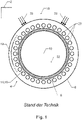
- FIG. 1 shows only schematically indicated a missile 2, here an IDAS guided missile.
- This includes a coil 4 shown here in cross section.
- This coil 4 has a coil body 6 according to the prior art, here in the form of a right circular cylinder, to which a winding package 8 is applied.
- the coil former 6 extends along a central longitudinal axis 10, which here runs perpendicular to the plane of the drawing.
- the winding package 8 is a winding of an optical waveguide 12 which—only indicated symbolically here—extends around the bobbin 6 in a large number of turns in the circumferential direction (relative to the central longitudinal axis 10).
- the optical waveguide 12 is in this case a data conductor which—in a manner not explained in detail—next to an actual optical waveguide and further fibers and a has envelope.
- the length of the optical waveguide 12 is approximately 20 km.
- the diameter of the bobbin is approx. 100 mm.
- the winding package 8 and thus the lowest turns of the optical waveguide 12 rest tightly on a radially outwardly pointing surface or lateral surface 14 of the coil former 6 . An interface 16 between the coil body 6 and the winding package 8 is thus formed.
- the following problem occurs. After the launch of the missile 2 from a submarine, not shown, it moves under water, as a result of which the outer space 18 is flooded with water 32 .
- the winding package 8 is soaked through from radially outside with the aid of penetrating water 32 (indicated here by arrows). However, air 20 , indicated here by bubbles, remains radially inside in the winding package 8 and does not escape or is not displaced by water 32 .
- the winding pack 8 is therefore not completely moistened, which leads to problems when the optical waveguide 12 is unwound.
- the bobbin 6 also has an interior space 22 .
- FIG figure 2 shows a coil 4 in a perspective view.
- the bobbin 6 according to the invention differs from that of FIG figure 1 .
- the winding package 8 and the rest of the missile 2 are identical to that of 1 .
- the winding package 8 does not cover the entire lateral surface 14, but ends at a distance from the axial longitudinal ends 24a, b of the coil former 6, as shown in FIG figure 2 is indicated by dashed lines.
- the winding package 8 therefore only covers a winding section 26 (indicated by an arrow) in the form of a longitudinal section (relative to the central longitudinal axis 10) of the lateral surface 14.
- the winding package 8 is therefore only applied to the coil body 6 in the winding section 26.
- the lateral surface 14 has an outlet means 28 .
- This serves to transport air 20 away (indicated by dashed arrows) from the winding section 26 or from the lateral surface 14 or boundary surface 16 .
- the interface 16 corresponds to the radially inner surface of the winding package 8. The transport takes place here towards the interior 22 with the help of openings 30 of the coil body 6.
- the partial curvature of the arrows symbolizing the air 20 indicates that air 20 is not only from the interface 16 itself, but also radially outwards from the interior of the winding package 8 is transported away. So will the according figure 1 indicated residual air 20 removed from the winding package 8 and the winding package 8 is completely moistened.
- the lateral surface 14 continues to be different 1 also an inlet means 34 .
- This serves for the admission of water 32 from the outer space 18 to the winding section 26 or the boundary surface 16 and thus to the radially inner surface of the winding stack 8 .
- the inflow of water 32 enhances the effect of transporting air 20 away from the winding pack 8 along the dashed arrows and finally through the outlet means 28 .
- Inlet means 34 and outlet means 28 thus interact in order to jointly effect the transport of water 32 or air 20 entrained or displaced thereby through or out of the winding pack 8 .
- the outlet means 28 is set up to transport air 20 away to the interior space 22.
- Outlet means 28 and inlet means 34 are formed by geometric structuring of the lateral surface 14:
- the geometric structuring consists in that the outlet means 28 contains grooves 36 and the inlet means 34 contains grooves 40, which are introduced radially inwards into the lateral surface 14.
- the grooves 36 exclusively have a longitudinal component (with respect to the central longitudinal axis 10 ), that is to say they are in the form of straight lines which run parallel to the central longitudinal axis 10 .
- the openings 30 in the form of radially inward bores are located at the respective bottom of the grooves 36.
- the grooves 36 are located completely within the winding section 26, ie they are spaced apart from its respective longitudinal ends 38a, b by a respective minimum distance dmin. In the peripheral edge formed by the distance dmin, the winding section 26 is sealed off from the outer space 18 by the tightly fitting winding package 8 . Thus, no water 32 can get from the exterior 18 directly into the interior 22 through the grooves 36 and openings 30 .
- the grooves 40 protrude beyond the winding section 26 at its longitudinal ends 38a, b. Water 32 can thus flow unhindered from the outer space 18 into the grooves 40 and be transported into the winding section 26 and from there into the winding package 8 .
- the interior 22 is a closed cavity here and has a valve 42, only indicated symbolically here, which allows the interior 22 to be emptied as soon as the missile 2 has passed from the water into the air during its mission.
- figure 3 shows a cross section at the longitudinal position III-III through the coil 4, the grooves 36 each having openings 30 at this longitudinal position.
- the outlet means 28 has a total of six grooves 36
- the inlet means 34 has six grooves 40, each of which is distributed over the circumference of the coil body 6 in an alternating manner adjacent to and equally spaced apart from one another.
- the grooves 36, 40 do not penetrate the coil body 6, but are only introduced into its radially outward surface or lateral surface 14. Only the openings 30 form a connection and thus a flow channel for air 20 / water 32 from the interface 16 to the interior 22 .
- figure 3 shows again the circular cross-section of both the coil body 6 and the entire coil 4 including the winding package 8.
- figure 3 clarifies once again that air 20 and water 32 trapped along the dashed arrows are transported away not only directly from the interface 16 but also from the interior of the winding package 8 or that inflowing water 32 displaces the trapped air 20, takes it with it and thereby transports it away.
- the width of the grooves 36, 40 in the circumferential direction is 0.8 mm here, which corresponds to approximately 0.25% of the circumference of the coil former 6.
- the outlet means 28 is a component of at least one part of at least one section formed in the coil body 6, i.e. in particular in its lateral surface 14, in one or more directions, i.e. e.g. in the axial direction and/or circumferential direction with respect to the longitudinal central axis 10, along the lateral surface 14 of the coil body 6 can form a first flow channel-comprising flow channel structure.
- This also means that the outlet means 28 communicates in terms of flow with a corresponding first flow channel.
- a corresponding first flow channel is functionally considered set up in particular to remove any air 20 and, if necessary, water 32 from the winding section 26 . From this it follows that a corresponding first flow channel typically extends at least in sections in the area of the winding section 26 of the coil body 6 .
- the or a corresponding inlet means 35 can be a part of a coil body 6, i. H. in particular in its lateral surface 14, at least one formed at least in sections in one or more directions, d. H. e.g. B. in the axial direction and / or circumferential direction with respect to the longitudinal center axis 10, along the lateral surface 14 of the bobbin 6 extending second flow channel comprehensive flow channel structure form.
- the inlet means 34 communicates in terms of flow with a corresponding second flow channel.
- a corresponding second flow channel is set up in particular for the inlet of water 32 from the outer space 18 of the coil body 6 to the winding section 26 . From this it follows that a corresponding second flow channel typically extends at least in sections outside of the winding section 26 of the coil body 6 .
- the bobbin 6 can thus in the region of its lateral surface 14 with at least one at least partially in one or more directions, d. H. e.g. B. in the axial direction and / or in the circumferential direction, extending first and / or second flow channel may be formed.
- Each flow channel can be subdivided into several flow channel segments, which are designed to extend in the same or different directions along the coil body 6 .
- each flow channel z. B. by a corresponding geometric structuring of the lateral surface 14, d. H. e.g. B. by a groove-like or -shaped recess in the lateral surface 14 may be formed.
- both at least one first and at least one second flow channel can communicate with each other, in particular in such a way that a fluid, such as. B. water 32, flow from the or a second flow channel into the or a first flow channel and thus from the inlet means 34 to the outlet means 28 flow.
- a fluid such as. B. water 32
- respective first and second flow channels can be arranged to cooperate in such a way that any water that is let in can Air is displaced from the winding pack 26 towards the outlet means 28 .
- a targeted guiding, ie in particular supplying and removing a fluid, along the lateral surface 14 of the coil body 6 can be realized in this way via a suitable spatial configuration of respective flow channels.
Landscapes
- Engineering & Computer Science (AREA)
- General Engineering & Computer Science (AREA)
- Chemical & Material Sciences (AREA)
- Aviation & Aerospace Engineering (AREA)
- Combustion & Propulsion (AREA)
- Mechanical Engineering (AREA)
- Light Guides In General And Applications Therefor (AREA)
- Aiming, Guidance, Guns With A Light Source, Armor, Camouflage, And Targets (AREA)
Abstract
Description
- Die Erfindung betrifft einen Spulenkörper zum Tragen eines Wickelpakets eines Lichtwellenleiters, wobei der Spulenkörper für einen unter Wasser startbaren Flugkörper bestimmt ist, wobei der Flugkörper mit dem Spulenkörper und dem Wickelpaket dazu eingerichtet ist, sich bei einer Mission zuerst durch Wasser und anschließend durch Luft zu bewegen und ab Beginn der Mission den Lichtwellenleiter hinter sich abzuwickeln.
- Bei zu einer Mission ausgeschickten Flugkörpern kann es vorkommen, dass die Notwendigkeit besteht, dass der Flugkörper während der gesamten Missionszeit mit einer Lenk- beziehungsweise Leitstelle verbunden bleiben muss, um Bild,- Zustands- oder Navigationsdaten austauschen zu können. Dies kann durch einen Datenleiter realisiert werden, der als Daten- oder Signalübertragungsleitung für die Übertragung von Signalen vorbereitet ist. Wegen der hohen Übertragungsbandbreite und gleichzeitig geringer Signaldämpfung werden solche Datenleiter üblicherweise als Lichtwellenleiter ausgeführt. Der Datenleiter ist in einer Spule aufgewickelt und mit einer Spindel / einem Spulenkörper verbunden, die das Wickelpaket trägt. Während der Fahrt (im Wasser) oder während des Flugs (in der Luft) des Flugkörpers wird der Datenleiter von der Spule abgewickelt, sodass die Datenverbindung zwischen einer Sende- beziehungsweise Empfangsstation der Leitstelle und dem bewegten Flugkörper erhalten bleibt. Hierbei ist die abwickelnde Spule üblicherweise am oder im Flugkörper angeordnet, damit der abgewickelte Datenleiter möglichst stationär im Luft- oder Wasserraum verbleiben kann.
- Aus der
EP 2 887 005 A1 ist ein Spulensystem dieser Art für ein Fahrzeug, insbesondere für einen Lenkflugkörper, bekannt, umfassend eine Unterwasserspule mit zumindest einer Spindel und zumindest einem Wickelpaket, die für einen Abzug bei einer Unterwasserfahrt des Fahrzeugs vorbereitet ist, eine Luftspule mit zumindest einer Spindel und zumindest einem Wickelpaket, die für einen nachfolgenden Abzug in der Luft bis zu einem Ziel und für einen Verbleib am Fahrzeug bis dahin vorbereitet ist, und einen auf beiden Spulen aufgewickelten, durchgehenden Datenleiter. Um ein Verheddern des Datenleiters am Übergang zwischen einem Unterwasserabschnitt und einem Luftabschnitt des Datenleiters zu vermeiden, wird vorgeschlagen, dass die Unterwasserspule abwurffest an der Luftspule befestigt ist. - Die Abwicklung des Lichtwellenleiters vom Spulenkörper ist nicht unproblematisch.
- Aufgabe der Erfindung ist es, Verbesserungen hinsichtlich dieser Abwicklung vorzuschlagen.
- Die Aufgabe wird gelöst durch einen Spulenkörper nach Anspruch 1. Bevorzugte oder vorteilhafte Ausführungsformen der Erfindung sowie anderer Erfindungskategorien ergeben sich aus den weiteren Ansprüchen, der nachfolgenden Beschreibung sowie den beigefügten Figuren.
- Der Spulenkörper dient zum Tragen eines bestimmungsgemäßen Wickelpakets. Das Wickelpaket enthält einen als Paket aufgewickelten Lichtwellenleiter. Unter "Lichtwellenleiter" wird hier entweder ein reiner Lichtwellenleiter, aber auch ein oben genannter Datenleiter, also eine Leiteranordnung verstanden, die neben dem Lichtwellenleiter noch andere Elemente, z.B. eine parallele Leitung / Kabel / Faser, eine Umhüllung usw. enthält. Der Spulenkörper ist für einen unter Wasser, insbesondere von einem Unterseeboot aus, startbaren Flugkörper bestimmt. Der Flugkörper ist mit dem in ihm montierten Spulenkörper und dem Wickelpaket dazu eingerichtet, sich bei einer Mission zuerst durch Wasser und anschließend durch Luft zu bewegen. Ab Beginn der Mission wickelt der Flugkörper dabei den Lichtwellenleiter zuerst unter Wasser, dann in der Luft, hinter sich ab. Der Flugkörper ist insbesondere ein IDAS (Interactive Defence and Attack system for Submarines), der von einem getaucht fahrenden U-Boot aus abgefeuert werden kann.
- "Bestimmungsgemäß" bzw. "bestimmt" heißt, dass das Element, z.B. der Spulenkörper auf eine bestimmte oder einen bestimmten Typ von Gegenstück, z.B. ein Wickelpaket, einen Lichtwellenleiter, einen Flugkörper, eine Art von Mission, eine Art von Abwicklung etc. konstruktiv abgestimmt ist und für den Einsatz dort vorgesehen bzw. dahingehend ausgelegt / konstruiert ist; z.B. für die dadurch bestimmten Geometrieanforderungen usw. ausgelegt ist.
- Der Spulenkörper erstreckt sich entlang einer Mittellängsachse und weist eine bezüglich dieser Achse radial nach außen weisende Mantelfläche auf. Der Spulenkörper umgibt dabei einen bzw. seinen Innenraum. Ein Längsabschnitt ("Länge" bezieht sich auf die Mittellängsachse) der Mantelfläche bildet einen Wickelabschnitt zur Aufbringung des Wickelpakets. Das Wickelpaket ist also in Längsrichtung des Spulenkörpers gesehen auf die Länge des Wickelabschnitts der Mantelfläche bzw. des Spulenkörpers begrenzt. Der Wickelabschnitt kann auch die gesamte Länge der Mantelfläche einnehmen.
- Die Mantelfläche weist ein Auslassmittel auf. Das Auslassmittel dient bzw. ist eingerichtet zum Abtransport von eventueller -jedoch in der Regel - vorhandener Luft und gegebenenfalls von Wasser aus dem Wickelabschnitt, d.h. bei montiertem Wickelpaket von einer Grenzfläche zwischen Wickelpaket und Spulenkörper weg. Die Grenzfläche stellt einerseits die Oberfläche des Spulenkörpers bzw. der Mantelfläche bzw. des Wickelabschnitts dar. Andererseits ist die Grenzfläche die radial einwärts weisende innere Oberfläche des Wickelpakets, mit der das Wickelpaket an der Mantelfläche bzw. dem Wickelabschnitt anliegt. Die Grenzfläche ist mit anderen Worten die Zwischenfläche zwischen bzw. die Berührungsfläche von Wickelpaket und Spulenkörper
- Nach dem Aufbringen des Wickelpakets liegt dieses mit seiner inneren Oberfläche bzw. die Innerste Lage Lichtwellenleiter mit Kontakt am Wickelabschnitt bzw. der Mantelfläche an. Zwischen den Windungen des Lichtwellenleiters verbleiben im Wickelpaket Zwischenräume / Hohlräume sowohl an Grenzfläche als auch im gesamten Wickelpaket. Luft / Wasser kann von diesen Hohlräumen bis zur Grenzfläche / der Mantelfläche / dem Wickelabschnitt gelangen und von dort durch das Auslassmittel abtransportiert werden..
- Mit anderen Worten ist - im bestimmungsgemäßen Montagezustand des Wickelpakets - die Grenzfläche zwischen Wickelpaket und Spulenkörper und damit die radial innere Oberfläche des Wickelpakets erfindungsgemäß mit dem Auslassmittel versehen. Der Spulenkörper und das Wickelpaket bilden - im bestimmungsgemäßen Montagezustand - zusammen eine Spule für den bzw. im Flugkörper. Der Flugkörper enthält dann die Spule.
- Die Erfindung beruht auf folgenden Erkenntnissen bzw. Beobachtungen: Bei geringen Wasserdrücken (z.B. geringen Tauchtiefen eines einen Flugkörper mit Spule abfeuernden U-Bootes) kann es vorkommen, dass in der durch die Launchsequenz des Flugkörpers bestimmten Flutungszeit (Zeit des Kontakts der Spule mit Umgebungs- / Außenraumwasser) keine vollständige Durchfeuchtung des Wickelpakets (Spulenpakets) der Lichtwellenleiter-Spule des Flugkörpers gemäß Stand der Technik erreicht wird. Die vollständige Durchfeuchtung des Wickelpakets ist jedoch eine notwendige Voraussetzung für einen erfolgreichen Abspulvorgang mit einem in der Praxis verwendeten Lichtwellenleiter-Aufbau (LWL Kabelaufbau / Datenleiter). Die Gründe hierfür sollen an dieser Stelle nicht weiter erläutert werden.
- Bei Flutungsversuchen mit Spulen nach dem Stand der Technik konnte die Luft im teildurchlässigen Wickelpaket bei der Flutung nicht aus dem Wickelpaket entweichen. Bei geringem Flutungsdruck verhinderte die eingeschlossene Luft die vollständige Durchfeuchtung.
- Gemäß der Erfindung wird nun über das Auslassmittel diese zu Missionsbeginn im Wickelpaket vorhandene Luft bei gleichem Flutungsdruck und gleicher Flutungszeit besser bzw. schneller aus der Spule entfernt. So wird eine bessere bzw. schnellere Durchfeuchtung des Wickelpakets erreicht. Durch das an der Mantelfläche angeordnete Auslassmittel kann Luft auch über die Mantelfläche bzw. Grenzfläche zwischen Wickelpaket und Spulenkörper aus dem Wickelpaket entweichen. Bei Aufliegen des Wickelpakets auf einer Oberfläche bzw. Mantelfläche ohne Auslassmittel nach dem Stand der Technik (z.B. glatt, unstrukturiert) war die radial einwärtige innere Oberfläche des Wickelpakets (Grenzfläche) bisher für das Entweichen von Luft abgedichtet, stand also hierfür nicht zur Verfügung.
- Dank der nunmehr geschaffenen "Entlüftung" an der Grenzfläche durch das Auslassmittel erfolgt eine schnelle und vollständige Durchfeuchtung des Wickelpakets. Hierdurch erfolgt ein erfolgreicher Abspulvorgang.
- In einer bevorzugten Ausführungsform weist die Mantelfläche ein Einlassmittel zum Einlass von Wasser aus der Umgebung bzw. einem Außenraum des Spulenkörpers zum Wickelabschnitt hin auf. Der Außenraum ist derjenige Raum, der den Spulenkörper mit aufgebrachtem Wickelpaket umgibt. Im Betrieb ist der Außenraum - zumindest teilweise - mit Wasser geflutet. Insbesondere ist das Wickelpaket im Betrieb, beim Missionsbeginn (z.B. in einem Torpedorohr eines Unterseebootes) und während der Tauchfahrt vollständig mit Wasser umgeben. Einlassmittel und Auslassmittel sind dabei derart zu einem Zusammenwirken eingerichtet, dass - im Betrieb und bei montiertem Wickelpaket, d.h. bei Flutung der fertigen Spule während einer Mission unter Wasser - mit Hilfe des über das Einlassmittel eingelassenen Wassers eventuelle Luft aus dem Wickelpaket zum Auslassmittel hin verdrängt wird. Das Zusammenwirken führt also dazu, dass im Betrieb Wasser durch das Einlassmittel zur Grenzfläche zwischen Wickelpaket und Spulenkörper strömt und damit auch radial auswärts in die innere Oberfläche des Wickelpakets eindringt. So stellt sich eine Strömung von der Grenzfläche durch zumindest einen Teil des Wickelpakets und zurück zur Grenzfläche ein. Luft und ggf. Wasser, das dann Luft mitführt wird dadurch aus zumindest einem Teil des Wickelkörpers verdrängt. Der Teil ist insbesondere derjenige, der nahe der Grenzfläche liegt. Dieser Bereich war nach dem Stand der Technik von Wasser, das zum Verdrängen der Luft nötig ist, schlecht erreichbar, da das Wasser bisher nur an der radial äußeren Fläche und ggf. an den Stirnseiten des Wickelpakets in dieses eindringen konnte.
- Insgesamt wird so die Verdrängung von Luft aus dem Wickelpaket dank des Einlassmittels weiter verbessert.
- In einer bevorzugten Ausführungsform ist das Auslassmittel zum Abtransport der Luft und gegebenenfalls des Wassers zum Innenraum hin eingerichtet. Luft / Wasser wird also von der Mantelfläche, insbesondere durch diese bzw. den Spulenkörper hindurch, zum Innenraum hin abtransportiert. Der Innenraum, vor allem wenn dieser ein geschlossener Hohlraum ist und somit nicht mit Umgebungswasser gefüllt ist oder wird, bietet den Vorteil, dass Luft / Wasser dort ungehindert einströmen kann, sodass ein besonders guter Abtransport von der Grenzfläche bzw. dem Wickelabschnitt stattfinden kann.
- In einer bevorzugten Ausführungsform ist das Auslassmittel und/oder - falls vorhanden - das Einlassmittel durch eine geometrische Strukturierung der Mantelfläche gebildet. Derartige geometrische Strukturen sind besonders einfach auf die Mantelfläche aufzubringen und/oder können besonders gut zur Führung von Luft / Wasser dienen. Die Strukturen sind dabei so gewählt, dass der darüber verlaufenden Lichtwellenleiter nicht geknickt oder unregelmäßig gebogen wird. Insbesondere sind die Strukturen sehr klein gegenüber dem Umfang des Spulenkörpers gewählt, insbesondere kleiner als 1 %, kleiner als 0,5 %, kleiner als 0,25 %.
- In einer bevorzugten Ausführungsform weist das Auslassmittel als geometrische Strukturierung mindestens eine in die Mantelfläche eingebrachte erste Nut auf. Dabei weist jede der ersten Nuten im Wickelabschnitt zumindest eine Längskomponente auf. Insbesondere weist - im Zusammenhang mit dem unten genannten Transport zum Innenraum hin - mindestens eine der ersten Nuten außerdem mindestens eine Durchbrechung zum Innenraum hin auf. Die Nuten sind in die Mantelfläche eingebracht und sind damit radial auswärts, also zum Wickelpaket hin geöffnet. Mit anderen Worten sind in die Mantelfläche radial einwärtig Kanäle eingebracht. "Zumindest eine Längskomponente" bedeutet, dass die Nuten sich wenigstens nicht vollständig in Umfangsrichtung erstrecken. Insbesondere verlaufen die Nuten an keiner Stelle in Umfangsrichtung, sondern deren Verlauf besitzt an jedem Ort eine Längskomponente, also Richtungskomponente in Längsrichtung, also parallel zur Mittellängsachse. Nuten können besonders einfach in die Mantelfläche eingebracht werden. Durch die Durchbrechungen, welche sich insbesondere am Nutgrund befinden, kann ein besonders einfacher Transport von Luft / Wasser zum Innenraum hin erfolgen. Durch die Längskomponente ist sichergestellt, dass die üblicherweise in Umfangsrichtung verlaufenden Lichtwellenleiter des Wickelpakets sich nicht in die Nuten einlegen und diese blockieren. Die Durchbrechung ist insbesondere eine Bohrung. Bohrungen sind besonders einfach in den Spulenkörper einzubringen. Insbesondere befinden sich die Bohrungen am Nutgrund und/oder verlaufen radial einwärts zum Innenraum hin.
- In einer bevorzugten Ausführungsform befindet sich mindestens eine der ersten Nuten vollständig innerhalb des Wickelabschnitts. Insbesondere befinden sich mehrere oder alle der ersten Nuten dort. "Innerhalb" ist so zu verstehen, dass die Nut an jeder Stelle einen jeweiligen Mindestabstand zu den Längsenden des Wickelabschnittes aufweist. Die Nuten sind so vom Wickelpaket vollständig überdeckt und weisen keinerlei Verbindung zum Außenraum hin auf. So wird erreicht, dass die ersten Nuten in erster Linie der Abfuhr von Luft dienen. Vor allem wenn die Nuten mithilfe von Durchbrechungen mit dem Innenraum kommunizieren, wird so vermieden, dass Wasser aus dem Außenraum in den Innenraum gelangt, ohne dabei zumindest Luft aus dem Wickelpaket mitzuführen. Denn Wasser im Innenraum kann insbesondere unerwünscht sein, wie weiter unten ausgeführt wird.
- In einer bevorzugten Ausführungsform weist das Einlassmittel als geometrische Strukturierung mindestens eine in die Mantelfläche eingebrachte zweite Nut auf, wobei jede der zweiten Nuten im Wickelabschnitt zumindest eine Längskomponente aufweist. Für die zweiten Nuten gelten sinngemäß die gleichen Aussagen wie für die ersten Nuten (radial auswärts, zum Wickelpaket hin geöffnet, Längskomponente, usw.). Im Betrieb dienen die zweiten Nuten jedoch der Zuführung von Wasser aus dem Außenraum zur Grenzfläche zwischen Wickelpaket und Mantelfläche hin und damit der Zufuhr von Wasser an die innere Oberfläche des Wickelpakets. Wie oben erläutert, soll dieses in das Wickelpaket zumindest teilweise eindringen und dort Luft - unter anderem zum Auslassmittel hin - aus dem Wickelpaket verdrängen bzw. herausdrängen.
- In einer bevorzugten Variante dieser Ausführungsform überragt mindestens eine der zweiten Nuten den Wickelabschnitt und damit dann auch das aufgebrachte Wickelpaket an wenigstens einem, insbesondere an beiden Längsenden mit einem Aufnahmeabschnitt für Wasser. Im Bereich des Aufnahmeabschnitts befindet sich kein Wickelpaket, sodass dort im Betrieb ein ungehindertes Zuströmen, also eine Aufnahme von Wasser aus dem Außenraum in die zweite Nut erfolgen kann. So wird sichergestellt, dass im Betrieb genügend Wasser durch das Einlassmittel dem Wickelabschnitt bzw. der Grenzfläche usw. zugeführt wird. Für den Fall, dass der Wickelabschnitt die gesamte Mantelfläche einnimmt, kann das "Überragen" auch darin bestehen, dass die Nut an einer nicht vom Wickelpaket verdeckten Stirnseite des Spulenkörpers offen ist und dort einen Wassereintritt ermöglicht.
- In einer bevorzugten Ausführungsform erstreckt sich mindestens eine, vorzugsweise mehrere oder alle, der ersten Nuten und/oder - falls vorhanden - mindestens eine, vorzugsweise mehrere oder alle, der zweiten Nuten entlang einer geraden Linie. Insbesondere handelt es sich dabei um eine sich in Längsrichtung erstreckende gerade Linie. Eine solche gerade Linie ergibt sich insbesondere bei Längsnuten auf Spulenkörpern, die eine Oberfläche in Form eines geraden Kreiszylinders oder Kegels aufweisen. Die Linie ist dann eine Längsgerade. Als "gerade Linie" wird hier auch eine Schraubenlinie auf der Mantelfläche verstanden, wenn eine solche Linie bei Abwicklung der Mantelfläche auf eine Ebene eine Gerade ergibt. Derartige Nuten sind fertigungstechnisch besonders einfach in einen Spulenkörper einzubringen.
- In einer bevorzugten Ausführungsform sind zumindest drei in Umfangsrichtung des Spulenkörpers um die Mittellängsachse benachbarte erste und zweite Nuten in Umfangrichtung alternierend angeordnet. "Zumindest drei" sind dabei zu verstehen als mindestens zwei erste ("1") und mindestens eine zweite Nut ("2") oder mindestens eine erste und mindestens zwei zweite Nuten. Insbesondere ist dabei stets die gleiche (gerade) Anzahl (also in Summe mindestens vier) von mindestens zwei ersten und mindestens zwei zweiten Nuten vorgesehen. In Umfangsrichtung ergeben sich also z.B. Nutfolgen von 1-2-1, 2-1-2, 1-2-1-2, 1-2-1-2 ... - 1 oder 1-2-1-2- ... -2.
- In einer bevorzugten Ausführungsform weist die Mantelfläche und/oder der Wickelabschnitt einen runden Querschnitt auf. Der Querschnitt ist insbesondere kreisförmig, insbesondere von gleichbleibendem Durchmesser entlang der Mittellängsachse. Die Mantelfläche und/oder der Wickelabschnitt ist insbesondere ein gerader Kreiszylinder. Derartige Spulenkörper eignen sich besonders gut für den beabsichtigten Einsatzzweck in einem Flugkörper.
- In einer bevorzugten Ausführungsform ist der Innenraum ein abgeschlossener Hohlraum. Derartige Spulenkörper sind besonders leicht und stabil herstellbar.
- In einer bevorzugten Variante dieser Ausführungsform weist der Innenraum ein Ventil zur Entleerung des Hohlraumes auf. Nachteil des abgeschlossenen Hohlraumes ist, dass sich eventuell durch das Auslassmittel im Betrieb eingebrachtes Wasser dort sammelt und für die weitere Mission des Flugkörpers mitgeführt werden muss. Durch ein Ventil kann dieses Wasser aus dem Hohlraum und somit dem gesamten Flugkörper entleert werden. Ein derartiges Ventil kann insbesondere gesteuert oder selbsttätig nach Übertritt des Flugkörpers vom Wasser in die Luft betätigt werden, um den Hohlraum zu leeren. So herrschen insbesondere für den durch die Luft führenden Abschnitt der Mission keine undefinierten (unbekannte Menge Wasser im Hohlraum) Masseverhältnisse im Flugkörper, was zu einem definierten Flugverhalten führt.
- Die Aufgabe der Erfindung wird auch gelöst durch eine Spule gemäß Patentanspruch 15. Die Spule enthält einen erfindungsgemäßen Spulenkörper und das Wickelpaket. Die Spule und zumindest ein Teil deren Ausführungsformen sowie die jeweiligen Vorteile wurden sinngemäß bereits im Zusammenhang mit dem erfindungsgemäßen Spulenkörper erläutert.
- Die Erfindung beruht auf folgenden Erkenntnissen, Beobachtungen bzw. Überlegungen und weist noch die nachfolgenden Ausführungsformen auf. Die Ausführungsformen werden dabei teils vereinfachend auch "die Erfindung" genannt. Die Ausführungsformen können hierbei auch Teile oder Kombinationen der oben genannten Ausführungsformen enthalten oder diesen entsprechen und/oder gegebenenfalls auch bisher nicht erwähnte Ausführungsformen einschließen.
- Gemäß der Erfindung ergibt sich eine - insbesondere durch den Spulenkörper gebildete - Vorrichtung zur zuverlässigen Durchfeuchtung des Spulenpakets bei Flutung der Lichtwellenleiterspule (Spule, Wickelpaket) in einem Flugkörper, z.B. einem IDAS.
- Insbesondere durch die Verbindung eines Innenraumes (Hohlraumes) im Spulenkörper durch Bohrungen und Kanäle (erste, ggf. auch zweite Nuten) mit dem Wickelpaket (bzw. dessen innerer Oberfläche / der Grenzfläche) wird eine zuverlässige Durchfeuchtung des Spulenpakets (Wickelpaket) der Spule (insb. LWL-Spule des IDAS) bei Flutung und geringem Wasserdruck sowie kurzer Flutungszeit erreicht. Der "geringe Wasserdruck" und die "kurze Flutungszeit" sind durch die operationellen Bedingungen des IDAS Flugkörpers bestimmt.
- Gemäß der Erfindung werden (zweite) Nuten in die Oberfläche eines Spulenkörpers eingebracht, so dass Wasser durch diese Nuten zur Zylinderfläche, die sich Wickelpaket und Wickelkörper teilen, also der Oberfläche des Spulenkörpers bzw. der Grenzfläche, gelangen kann. Diese (zweiten) Nuten sind länger als das Wickelpaket ausgeführt, überragen dieses also in Längsrichtung. Außerdem sind (erste), insbesondere kürzere, Nuten, in der Oberfläche (insbesondere Zylinderfläche) vorgesehen. Von diesen aus führen insbesondere Bohrungen in den (insbesondere zylinderförmigen) Hohlraum des Spulenkörpers. Im Gegensatz zu Ausführungen gemäß Stand der Technik stellt sich so eine Strömung vom Wickelpaket (Spulenpaket) in den Hohlraum ein, wenn das Spulenpaket mit Wasserüberdruck von außen (Außenraum) beaufschlagt wird. Die Luft kann dank des Auslassmittels vollständig aus dem Spulenpaket, nämlich insbesondere zumindest teilweise über die ersten Nuten mit Durchbrechungen in den Hohlraum, entweichen, so dass eine vollständige Durchfeuchtung des Wickelpakets erreicht werden kann.
- Nach dem Flutungsvorgang kann sich im Hohlraum des Spulenkörpers auch Wasser befinden, welches insbesondere über die Durchbrechungen zusammen mit Luft aus dem Wickelpaket entwichen ist. Diese Wassermenge soll aufgrund des Massenzuwachses des Flugkörpers möglichst geringgehalten werden. Zum einen kann das optimale Volumen durch Versuche ermittelt werden, so dass mit der geringstmöglichen Menge an Ballastwasser zuverlässige Durchfeuchtung erreicht werden kann. Zum anderen kann ein Ventil zum Ablassen des Ballastwassers aus diesem Hohlraum nach Austritt des Flugkörpers aus dem Wasser ebenfalls vorgesehen sein.
- Die Erfindung ermöglicht den zuverlässigen Abspulvorgang des Lichtwellenleiters bei allen Launchbedingungen eines Flugkörpers aus einem Unterseeboot (Tauchtiefe / Flutungsdauer) durch zuverlässige Durchfeuchtung des Spulenpakets. Die Erfindung bewirkt eine Verkürzung der Flutungszeit und/oder das Ausreichen geringeren Wasserüberdrucks, um das Wickelpaket ausreichend zu durchfeuchten.
- Die Grenzfläche entspricht neben der Mantelfläche des Spulenkörpers auch der radial inneren Oberfläche des Wickelpakets. An der Mantelfläche geschaffene Kanäle etc. führen daher dazu, dass die nach dem Stand der Technik dichtend anliegende Oberfläche des Spulenkörpers, die dabei ein Entweichen von Luft aus der inneren Oberfläche des Wickelpakets verhindert, durch das Auslassmittel eine Luft / Wasserströmung nunmehr zulässt. Luft / Wasser kann so auch an der radial inneren Oberfläche des Wickelpakets entweichen. Entsprechendes gilt für die Versorgung der inneren Oberfläche des Wickelpakets mit Wasser zur Verdrängung der Luft. Auch hier wird durch das Einlassmittel bzw. entsprechende Kanäle Wasser dorthin transportiert, was bei einer glatten bzw. dichten Oberfläche des Spulenkörpers nach dem Stand der Technik nicht möglich war.
- Für alle Ausführungsformen gilt, dass das Auslassmittel einen Bestandteil einer in dem Spulenkörper, d. h. insbesondere in dessen Mantelfläche, ausgebildeten, wenigstens einen sich zumindest abschnittsweise in einer oder mehreren Richtungen, d. h. z. B. in Axialrichtung und/oder Umfangsrichtung bezüglich der Längsmittelachse, entlang der Mantelfläche des Spulenkörpers erstreckenden ersten Strömungskanal umfassenden Strömungskanalstruktur bilden kann. Hierunter ist auch zu verstehen, dass das Auslassmittel strömungstechnisch mit einem entsprechenden ersten Strömungskanal kommuniziert. Funktional betrachtet kann ein entsprechender erster Strömungskanal insbesondere zum Abtransport von eventueller Luft und gegebenenfalls von Wasser aus dem Wickelabschnitt eingerichtet sein. Hieraus ergibt sich, dass ein entsprechender erster Strömungskanal sich typischerweise zumindest abschnittsweise im Bereich des Wickelabschnitts des Spulenkörpers erstreckt.
- Gleichermaßen kann das bzw. ein entsprechendes Einlassmittel einen Bestandteil einer in dem Spulenkörper, d. h. insbesondere in dessen Mantelfläche, ausgebildeten, wenigstens einen sich zumindest abschnittsweise in einer oder mehreren Richtungen, d. h. z. B. in Axialrichtung und/oder Umfangsrichtung bezüglich der Längsmittelachse, entlang der Mantelfläche des Spulenkörpers erstreckenden zweiten Strömungskanal umfassenden Strömungskanalstruktur bilden. Hierunter ist auch zu verstehen, dass das Einlassmittel strömungstechnisch mit einem entsprechenden zweiten Strömungskanal kommuniziert. Funktional betrachtet kann ein entsprechender zweiter Strömungskanal insbesondere zum Einlass von Wasser aus dem Außenraum des Spulenkörpers zum Wickelabschnitt eingerichtet sein. Hieraus ergibt sich, dass ein entsprechender zweiter Strömungskanal sich typischerweise zumindest abschnittsweise außerhalb des Wickelabschnitts des Spulenkörpers erstreckt.
- Der Spulenkörper kann sonach im Bereich seiner Mantelfläche mit wenigstens einem sich zumindest abschnittsweise in einer oder mehreren Richtungen, d. h. z. B. in Axialrichtung und/oder in Umfangsrichtung, entlang der Mantelfläche des Spulenkörpers erstreckenden ersten und/oder zweiten Strömungskanal ausgebildet sein. Jeder Strömungskanal kann gegebenenfalls in mehrere Strömungskanalsegmente unterteilt sein, welche sich in gleichen oder unterschiedlichen Richtungen entlang des Spulenkörpers erstreckend ausgebildet sind. Unabhängig von seiner konkreten räumlichen Erstreckung und/oder Segmentierung kann jeder Strömungskanal z. B. durch eine entsprechende geometrische Strukturierung, d. h. z. B. durch eine nutartige bzw. - förmige Vertiefung in der Mantelfläche des Spulenkörpers, ausgebildet sein.
- Sofern sowohl wenigstens ein erster als auch wenigstens ein zweiter Strömungskanal vorhanden ist, können diese miteinander kommunizieren, insbesondere derart, dass ein Fluid, wie z. B. Wasser, von dem bzw. einem zweiten Strömungskanal in den bzw. einen ersten Strömungskanal und damit von dem Einlassmittel zu dem Auslassmittel strömen kann. Derart können jeweilige erste und zweite Strömungskanäle zu einem Zusammenwirken eingerichtet sein, dass mithilfe von eingelassenem Wasser eventuelle Luft aus dem Wickelpacket zu dem Auslassmittel hin verdrängt wird. Weiterhin kann derart über eine geeignete räumliche Konfiguration jeweiliger erster und zweiter Strömungskanäle ein gezieltes Führen, d. h. insbesondere Zu- und Abführen eines Fluids, entlang der Mantelfläche des Spulenkörpers realisiert werden.
- Weitere Merkmale, Wirkungen und Vorteile der Erfindung ergeben sich aus der nachfolgenden Beschreibung eines bevorzugten Ausführungsbeispiels der Erfindung sowie der beigefügten Figuren. Dabei zeigen, jeweils in einer schematischen Prinzipskizze:
- Figur 1
- eine Spule in einem Flugkörper gemäß Stand der Technik,
- Figur 2
- einen erfindungsgemäßen Spulenkörper im Betrieb in perspektivischer Ansicht,
- Figur 3
- den Spulenkörper aus
Fig. 2 im Querschnitt entlang der Linie III-III. -
Fig. 1 . zeigt lediglich schematisch angedeutet einen Flugkörper 2, hier einen IDAS-Lenkflugkörper. Dieser beinhaltet eine hier im Querschnitt dargestellte Spule 4. Diese Spule 4 weist einen Spulenkörper 6 gemäß Stand der Technik, hier in Form eines geraden Kreiszylinders auf, auf den ein Wickelpaket 8 aufgebracht ist. Der Spulenkörper 6 erstreckt sich entlang einer Mittellängsachse 10, die hier senkrecht zur Zeichenebene verläuft. Das Wickelpaket 8 ist eine Wicklung eines Lichtwellenleiters 12, der sich - hier nur symbolisch angedeutet - in einer Vielzahl von Windungen in Umfangsrichtung (bezogen auf die Mittellängsachse 10) um den Spulenkörper 6 herum erstreckt. Der Lichtwellenleiter 12 ist hierbei strenggenommen ein Datenleiter, der - in nicht näher erläuterter Weise - neben einem eigentlichen Lichtwellenleiter weitere Fasern und eine Umhüllung aufweist. Die Länge des Lichtwellenleiters 12 beträgt ca. 20 km. Der Durchmesser des Spulenkörpers ca. 100 mm. Das Wickelpaket 8 und somit die untersten Windungen des Lichtwellenleiters 12 liegen dicht auf einer radial nach außen weisenden Oberfläche bzw. Mantelfläche 14 des Spulenkörpers 6 auf. Damit ist eine Grenzfläche 16 zwischen dem Spulenkörper 6 und dem Wickelpaket 8 gebildet. - Beim Einsatz der Spule 4 tritt folgendes Problem auf. Nach dem Start des Flugkörpers 2 von einem nicht dargestellten Unterseeboot aus bewegt sich dieser unter Wasser, wodurch der Außenraum 18 mit Wasser 32 geflutet wird. Das Wickelpaket 8 wird von radial außen her mit Hilfe von eindringendem Wasser 32 (hier durch Pfeile angedeutet) durchfeuchtet. Allerdings hält sich radial innen im Wickelpaket 8 Luft 20, hier angedeutet durch Blasen, die nicht entweicht bzw. nicht von Wasser 32 verdrängt wird. Das Wickelpaket 8 wird also nicht vollständig durchfeuchtet, was zu Problemen beim Abwickeln des Lichtwellenleiters 12 führt. Der Spulenkörper 6 weist außerdem einen Innenraum 22 auf.
-
Figur 2 zeigt eine Spule 4 in einer perspektivischen Ansicht. Der Spulenkörper 6 gemäß der Erfindung unterscheidet sich von dem ausFigur 1 . Das Wickelpaket 8 sowie der restliche Flugkörper 2 sind identisch zu dem ausFig. 1 . Das Wickelpaket 8 bedeckt nicht die gesamte Mantelfläche 14, sondern endet von den axialen Längsenden 24a, b des Spulenkörper 6 beanstandet, wie inFigur 2 durch gestrichelte Linien angedeutet ist. Das Wickelpaket 8 bedeckt daher lediglich einen Wickelabschnitt 26 (durch einen Pfeil angedeutet) in Form eines Längsabschnittes (bezüglich der Mittellängsachse 10) der Mantelfläche 14. Das Wickelpaket 8 ist also nur im Wickelabschnitt 26 auf den Spulenkörper 6 aufgebracht. - Die Mantelfläche 14 weist im Gegensatz zum Stand der Technik ein Auslassmittel 28 auf. Dieses dient zum Abtransport von Luft 20 (angedeutet durch gestrichelte Pfeile) aus dem Wickelabschnitt 26 bzw. von der Mantelfläche 14 bzw. Grenzfläche 16 weg. Die Grenzfläche 16 entspricht dabei der radial inneren Oberfläche des Wickelpakets 8. Der Transport erfolgt hier zum Innenraum 22 hin mit Hilfe von Durchbrechungen 30 des Spulenkörpers 6. Die teilweise Krümmung der die Luft 20 symbolisierenden Pfeile deutet an, dass Luft 20 nicht nur von der Grenzfläche 16 selbst, sondern auch radial auswärts aus dem Inneren des Wickelpaketes 8 abtransportiert wird. So wird auch die gemäß
Fig. 1 angedeutete Rest-Luft 20 aus dem Wickelpaket 8 entfernt und das Wickelpaket 8 vollständig durchfeuchtet. - Die Mantelfläche 14 weist weiterhin im Unterschied zu
Fig. 1 auch ein Einlassmittel 34 auf. Dieses dient zum Einlass von Wasser 32 aus dem Außenraum 18 zum Wickelabschnitt 26 bzw. der Grenzfläche 16 und damit zur radial inneren Oberfläche des Wickelpakets 8 hin. Der Zustrom des Wasser 32 verstärkt den Effekt, Luft 20 aus dem Wickelpaket 8 entlang der gestrichelten Pfeile und schließlich durch das Auslassmittel 28 abzutransportieren. Einlassmittel 34 und Auslassmittel 28 wirken also zusammen, um gemeinsam den Transport von Wasser 32 bzw. dadurch mitgeführter oder verdrängter Luft 20 durch das bzw. aus dem Wickelpaket 8 zu bewirken. - Mit Hilfe der Durchbrechungen 30 ist das Auslassmittel 28 dazu eingerichtet, Luft 20 zum Innenraum 22 hin abzutransportieren.
- Auslassmittel 28 und Einlassmittel 34 sind die durch geometrische Strukturierung der Mantelfläche 14 gebildet: Die geometrische Strukturierung besteht darin, dass das Auslassmittel 28 Nuten 36 und das Einlassmittel 34 Nuten 40 enthält, die radial einwärts in die Mantelfläche 14 eingebracht sind. Die Nuten 36 weisen bezüglich ihrer Erstreckungsrichtung ausschließlich eine Längskomponente (bzgl. der Mittellängsachse 10) auf, sind also in Form von Geraden ausgeführt, die parallel zur Mittellängsachse 10 verlaufen. Die Durchbrechungen 30 in Form von radial einwärtigen Bohrungen befinden sich am jeweiligen Nutgrund der Nuten 36.
- Die Nuten 36 befinden sich vollständig innerhalb des Wickelabschnitts 26, sind also von dessen jeweiligen Längsenden 38a, b durch einen jeweiligen Mindestabstand dmin beanstandet. Im durch den Abstand dmin gebildeten in Umfansrichtung umlaufenden Rand ist der Wickelabschnitt 26 vom Außenraum 18 durch das dicht anliegende Wickelpaket 8 abgedichtet. So kann kein Wasser 32 aus dem Außenraum 18 durch die Nuten 36 und Durchbrechungen 30 unmittelbar in den Innenraum 22 gelangen.
- Die Nuten 40 überragen den Wickelabschnitt 26 an dessen Längsenden 38a, b. So kann Wasser 32 ungehindert aus dem Außenraum 18 in die Nuten 40 einströmen und in den Wickelabschnitt 26 und von dort in das Wickelpaket 8 hinein transportiert werden.
- Der Innenraum 22 ist hier ein abgeschlossener Hohlraum und weist ein hier nur symbolisch angedeutetes Ventil 42 auf, das eine Entleerung des Innenraums 22 ermöglicht, sobald der Flugkörper 2 bei seiner Mission aus dem Wasser in die Luft übergetreten ist.
-
Figur 3 zeigt einen Querschnitt an der Längsposition III-III durch die Spule 4, wobei an dieser Längsposition die Nuten 36 jeweils Durchbrechungen 30 aufweisen. Das Auslassmittel 28 weist insgesamt sechs Nuten 36, das Einlassmittel 34 sechs Nuten 40 auf, die jeweils alternierend benachbart und gleich beabstandet über den Umfang des Spulenkörper 6 verteilt sind.Figur 3 zeigt, dass die Nuten 36, 40 den Spulenkörper 6 jeweils nicht durchdringen, sondern nur in dessen radial auswärtige Oberfläche bzw. Mantelfläche 14 eingebracht sind. Lediglich die Durchbrechungen 30 bilden eine Verbindung und damit einen Strömungskanal für Luft 20 / Wasser 32 von der Grenzfläche 16 zum Innenraum 22 hin.Figur 3 zeigt nochmals den kreisrunden Querschnitt sowohl des Spulenkörper 6 als auch der gesamten Spule 4 einschließlich Wickelpaket 8. -
Figur 3 verdeutlicht nochmals, dass entlang der gestrichelten Pfeile eingeschlossene Luft 20 und Wasser 32 nicht nur direkt von der Grenzfläche 16, sondern auch aus dem Inneren des Wickelpakets 8 abtransportiert werden bzw. dass einströmendes Wasser 32 die eingeschlossene Luft 20 verdrängt, mitnimmt und dadurch abtransportiert. - Die Breite der Nuten 36, 40 in Umfangsrichtung beträgt hier 0,8mm, was ca. 0,25% des Umfangs des Spulenkörpers 6 entspricht.
- Wenngleich in den Fig. nicht gezeigt, gilt für alle Ausführungsbeispiele, dass das Auslassmittel 28 einen Bestandteil einer in dem Spulenkörper 6, d. h. insbesondere in dessen Mantelfläche 14, ausgebildeten, wenigstens einen sich zumindest abschnittsweise in einer oder mehreren Richtungen, d. h. z. B. in Axialrichtung und/oder Umfangsrichtung bezüglich der Längsmittelachse 10, entlang der Mantelfläche 14 des Spulenkörpers 6 erstreckenden ersten Strömungskanal umfassenden Strömungskanalstruktur bilden kann. Hierunter ist auch zu verstehen, dass das Auslassmittel 28 strömungstechnisch mit einem entsprechenden ersten Strömungskanal kommuniziert. Funktional betrachtet ist ein entsprechender erster Strömungskanal insbesondere zum Abtransport von eventueller Luft 20 und gegebenenfalls von Wasser 32 aus dem Wickelabschnitt 26 eingerichtet. Hieraus ergibt sich, dass ein entsprechender erster Strömungskanal sich typischerweise zumindest abschnittsweise im Bereich des Wickelabschnitts 26 des Spulenkörpers 6 erstreckt.
- Gleichermaßen kann das bzw. ein entsprechendes Einlassmittel 35 einen Bestandteil einer in dem Spulenkörper 6, d. h. insbesondere in dessen Mantelfläche 14, ausgebildeten, wenigstens einen sich zumindest abschnittsweise in einer oder mehreren Richtungen, d. h. z. B. in Axialrichtung und/oder Umfangsrichtung bezüglich der Längsmittelachse 10, entlang der Mantelfläche 14 des Spulenkörpers 6 erstreckenden zweiten Strömungskanal umfassenden Strömungskanalstruktur bilden. Hierunter ist auch zu verstehen, dass das Einlassmittel 34 strömungstechnisch mit einem entsprechenden zweiten Strömungskanal kommuniziert. Funktional betrachtet ist ein entsprechender zweiter Strömungskanal insbesondere zum Einlass von Wasser 32 aus dem Außenraum 18 des Spulenkörpers 6 zum Wickelabschnitt 26 eingerichtet. Hieraus ergibt sich, dass ein entsprechender zweiter Strömungskanal sich typischerweise zumindest abschnittsweise außerhalb des Wickelabschnitts 26 des Spulenkörpers 6 erstreckt.
- Der Spulenkörper 6 kann sonach im Bereich seiner Mantelfläche 14 mit wenigstens einem sich zumindest abschnittsweise in einer oder mehreren Richtungen, d. h. z. B. in Axialrichtung und/oder in Umfangsrichtung, erstreckenden ersten und/oder zweiten Strömungskanal ausgebildet sein. Jeder Strömungskanal kann in mehrere Strömungskanalsegmente unterteilt sein, welche sich in gleichen oder unterschiedlichen Richtungen entlang des Spulenkörpers 6 erstreckend ausgebildet sind. Unabhängig von seiner konkreten räumlichen Erstreckung kann jeder Strömungskanal z. B. durch eine entsprechende geometrische Strukturierung der Mantelfläche 14, d. h. z. B. durch eine nutartige bzw. -förmige Vertiefung in der Mantelfläche 14, ausgebildet sein.
- Sofern sowohl wenigstens ein erster als auch wenigstens ein zweiter Strömungskanal vorhanden ist, können diese miteinander kommunizieren, insbesondere derart, dass ein Fluid, wie z. B. Wasser 32, von dem bzw. einem zweiten Strömungskanal in den bzw. einen ersten Strömungskanal und damit von dem Einlassmittel 34 zu dem Auslassmittel 28 strömen. Derart können jeweilige erste und zweite Strömungskanäle zu einem Zusammenwirken eingerichtet sein, dass mithilfe von eingelassenem Wasser eventuelle Luft aus dem Wickelpacket 26 zu dem Auslassmittel 28 hin verdrängt wird. Weiterhin kann derart über eine geeignete räumliche Konfiguration jeweiliger Strömungskanäle ein gezieltes Führen, d. h. insbesondere Zu- und Abführen eines Fluids, entlang der Mantelfläche 14 des Spulenkörpers 6 realisiert werden.
-
- 2
- Flugkörper
- 4
- Spule
- 6
- Spulenkörper
- 8
- Wickel paket
- 10
- Mittellängsachse
- 12
- Lichtwellenleiter
- 14
- Mantelfläche
- 16
- Grenzfläche
- 18
- Außenraum
- 20
- Luft
- 22
- Innenraum
- 24a, b
- Längsende (Spulenkörper)
- 26
- Wickelabschnitt
- 28
- Auslassmittel
- 30
- Durchbrechung
- 32
- Wasser
- 34
- Einlassmittel
- 36
- erste Nut (Auslassmittel)
- 38a, b
- Längsende (Wickelabschnitt)
- 40
- zweite Nut (Einlassmittel)
- 42
- Ventil
- dmin
- Mindestabstand
Claims (17)
- Spulenkörper (6) zum Tragen eines Wickelpakets (8) eines Lichtwellenleiters (12), wobei der Spulenkörper (6) für einen unter Wasser startbaren Flugkörper (2) bestimmt ist, wobei der Flugkörper (2) mit dem Spulenkörper (6) und dem Wickelpaket (8) dazu eingerichtet ist, sich bei einer Mission zuerst durch Wasser und anschließend durch Luft zu bewegen und ab Beginn der Mission den Lichtwellenleiter (12) hinter sich abzuwickeln, wobei- der Spulenkörper (6) sich entlang einer Mittellängsachse (10) erstreckt und eine radial nach außen weisende Mantelfläche (14) aufweist und einen Innenraum (22) umgibt,- ein Längsabschnitt der Mantelfläche (14) einen Wickelabschnitt (26) zur Aufbringung des Wickelpakets (8) bildet,- die Mantelfläche (14) ein Auslassmittel (28) zum Abtransport von eventueller Luft (20) und gegebenenfalls von Wasser (32) aus dem Wickelabschnitt (26) aufweist.
- Spulenkörper (6) nach Anspruch 1,
dadurch gekennzeichnet, dass
die Mantelfläche (14) ein Einlassmittel (34) zum Einlass von Wasser (32) aus dem Außenraum (18) des Spulenkörpers (6) zum Wickelabschnitt (26) hin aufweist, wobei Einlassmittel (34) und Auslassmittel (28) derart zu einem Zusammenwirken eingerichtet sind, dass mit Hilfe des eingelassenen Wassers (32) eventuelle Luft (20) aus dem Wickelpaket (26) zum Auslassmittel (28) hin verdrängt wird. - Spulenkörper (6) nach einem der vorhergehenden Ansprüche,
dadurch gekennzeichnet, dass
das Auslassmittel (28) zum Abtransport der Luft (20) und gegebenenfalls des Wassers (32) zum Innenraum (22) hin eingerichtet ist. - Spulenkörper (6) nach einem der vorhergehenden Ansprüche,
dadurch gekennzeichnet, dass
das Auslassmittel (28) und/oder - falls vorhanden - das Einlassmittel (34) durch eine geometrische Strukturierung der Mantelfläche (14) gebildet ist. - Spulenkörper (6) nach Anspruch 4,
dadurch gekennzeichnet, dass
das Auslassmittel (28) als geometrische Strukturierung mindestens eine in die Mantelfläche (14) eingebrachte erste Nut (36) aufweist, wobei jede der ersten Nuten (36) im Wickelabschnitt (26) zumindest eine Längskomponente aufweist. - Spulenkörper (6) nach Anspruch 5,
dadurch gekennzeichnet, dass
mindestens eine der ersten Nuten (36) eine Durchbrechung (30) zum Innenraum (22) hin aufweist. - Spulenkörper (6) nach einem der Ansprüche 5 bis 6,
dadurch gekennzeichnet, dass
mindestens eine der ersten Nuten (36) sich vollständig innerhalb des Wickelabschnitts (26) befindet. - Spulenkörper (6) nach einem der Ansprüche 4 bis 7,
dadurch gekennzeichnet, dass
das Einlassmittel (34) als geometrische Strukturierung mindestens eine in die Mantelfläche (14) eingebrachte zweite Nut (40) aufweist, wobei jede der zweiten Nuten (40) im Wickelabschnitt (14) zumindest eine Längskomponente aufweist. - Spulenkörper (6) nach Anspruch 8,
dadurch gekennzeichnet, dass
mindestens eine der zweiten Nuten (40) den Wickelabschnitt (26) an wenigstens einem Längsende (38a, b) überragt. - Spulenkörper (6) nach einem der Ansprüche 5 bis 9,
dadurch gekennzeichnet, dass
sich mindestens eine der ersten Nuten (36) und/oder - falls vorhanden - mindestens eine der zweiten Nuten (40) entlang einer geraden Linie erstreckt. - Spulenkörper (6) nach einem der Ansprüche 5 bis 10,
dadurch gekennzeichnet, dass
zumindest drei in Umfangsrichtung benachbarte erste (36) und zweite Nuten (40) in Umfangrichtung alternierend angeordnet sind. - Spulenkörper (6) nach einem der vorhergehenden Ansprüche,
dadurch gekennzeichnet, dass
die Mantelfläche (14) und/oder der Wickelabschnitt (26) einen runden Querschnitt aufweist. - Spulenkörper (6) nach einem der vorhergehenden Ansprüche,
dadurch gekennzeichnet, dass
der Innenraum (22) ein abgeschlossener Hohlraum ist. - Spulenkörper (6) nach Anspruch 13,
dadurch gekennzeichnet, dass
der Innenraum (22) ein Ventil (42) zur Entleerung des Hohlraumes aufweist. - Spulenkörper nach einem der vorhergehenden Ansprüche, dadurchgekennzeichnet, dass das Auslassmittel (28) einen Bestandteil einer in dem Spulenkörper (6) ausgebildeten, wenigstens einen sich zumindest abschnittsweise in einer oder mehreren Richtungen entlang der Mantelfläche (14) des Spulenkörpers (6) erstreckenden ersten Strömungskanal umfassenden Strömungskanalstruktur bildet; und/oderdas oder ein Einlassmittel (34) einen Bestandteil einer in dem Spulenkörper (6) ausgebildeten, wenigstens einen sich zumindest abschnittsweise in einer oder mehreren Richtungen entlang der Mantelfläche (14) des Spulenkörpers (6) erstreckenden zweiten Strömungskanal umfassenden Strömungskanalstruktur bildet.
- Spulenkörper nach Anspruch 15, dadurch gekennzeichnet, dass sowohl wenigstens ein erster als auch wenigstens ein zweiter Strömungskanal vorhanden ist, welche miteinander kommunizieren, insbesondere derart, dass ein Fluid, wie z. B. Wasser, von dem bzw. einem zweiten Strömungskanal in den bzw. einen ersten Strömungskanal und damit von dem Einlassmittel (34) zu dem Auslassmittel (28) strömen kann.
- Spule (4), mit einem Spulenkörper (6) nach einem der vorhergehenden Ansprüche, und mit dem Wickelpaket (8).
Applications Claiming Priority (1)
| Application Number | Priority Date | Filing Date | Title |
|---|---|---|---|
| DE102020006470.1A DE102020006470A1 (de) | 2020-10-21 | 2020-10-21 | Spulenkörper mit Mitteln zur Durchfeuchtung eines Wickelpakets |
Publications (2)
| Publication Number | Publication Date |
|---|---|
| EP3988890A1 true EP3988890A1 (de) | 2022-04-27 |
| EP3988890B1 EP3988890B1 (de) | 2025-08-13 |
Family
ID=78087046
Family Applications (1)
| Application Number | Title | Priority Date | Filing Date |
|---|---|---|---|
| EP21201673.7A Active EP3988890B1 (de) | 2020-10-21 | 2021-10-08 | Spulenkörper mit mitteln zur durchfeuchtung eines wickelpakets |
Country Status (3)
| Country | Link |
|---|---|
| EP (1) | EP3988890B1 (de) |
| DE (1) | DE102020006470A1 (de) |
| IL (1) | IL287297B2 (de) |
Citations (2)
| Publication number | Priority date | Publication date | Assignee | Title |
|---|---|---|---|---|
| DE19528347C1 (de) * | 1995-08-02 | 1996-11-07 | Daimler Benz Aerospace Ag | Wickelkörper |
| EP2887005A1 (de) | 2013-12-20 | 2015-06-24 | Diehl BGT Defence GmbH & Co. Kg | Spulensystem für ein Fahrzeug |
Family Cites Families (5)
| Publication number | Priority date | Publication date | Assignee | Title |
|---|---|---|---|---|
| DE3003155A1 (de) | 1980-01-30 | 1981-09-24 | Kabel- und Metallwerke Gutehoffnungshütte Kabelwerke Berlin GmbH, 1000 Berlin | Kabeltrommel oder -spule aus stahl |
| FR2650678B1 (fr) | 1989-08-04 | 1993-04-16 | Aerospatiale | Dispositif d'observation aerienne pour un sous-marin |
| WO1996018865A1 (en) | 1994-12-16 | 1996-06-20 | Sci Systems, Inc. | Fiber-optic cable dispenser and remotely controlled vehicle using same |
| US8334744B1 (en) | 2010-02-05 | 2012-12-18 | Lockheed Martin Company | Tether cable with increased thermal dissipation and method of tethering an underwater vehicle |
| US8556538B2 (en) | 2010-06-03 | 2013-10-15 | Bluefin Robotics Corporation | Deployable optical fiber cartridge |
-
2020
- 2020-10-21 DE DE102020006470.1A patent/DE102020006470A1/de active Pending
-
2021
- 2021-10-08 EP EP21201673.7A patent/EP3988890B1/de active Active
- 2021-10-14 IL IL287297A patent/IL287297B2/en unknown
Patent Citations (2)
| Publication number | Priority date | Publication date | Assignee | Title |
|---|---|---|---|---|
| DE19528347C1 (de) * | 1995-08-02 | 1996-11-07 | Daimler Benz Aerospace Ag | Wickelkörper |
| EP2887005A1 (de) | 2013-12-20 | 2015-06-24 | Diehl BGT Defence GmbH & Co. Kg | Spulensystem für ein Fahrzeug |
Also Published As
| Publication number | Publication date |
|---|---|
| IL287297B1 (en) | 2025-03-01 |
| DE102020006470A1 (de) | 2022-04-21 |
| IL287297A (en) | 2022-05-01 |
| IL287297B2 (en) | 2025-07-01 |
| EP3988890B1 (de) | 2025-08-13 |
Similar Documents
| Publication | Publication Date | Title |
|---|---|---|
| DE3633021C2 (de) | ||
| EP0215520B1 (de) | Verfahren zur Herstellung einer Verbindung zwischen zwei optischen Leitungen und Anordnung zur Ausübung des Verfahrens | |
| DE2922986C2 (de) | ||
| DE7310391U (de) | Patronenmunition | |
| DE3217922C2 (de) | ||
| DE2731093A1 (de) | Geschoss, insbesondere zum verschiessen aus einem glatten rohr | |
| EP0096847B1 (de) | Gerät zur Verteilung von Dipolen | |
| WO1979000037A1 (fr) | Projectile avec canaux de circulation provoquant une rotation | |
| DE1903700A1 (de) | Verfahren und Vorrichtung zur Bildung von Fluessigkeitssperren im Dielektrikum von luftraumisolierten Koaxialkabeln | |
| DE3000674A1 (de) | Lichtleitfasern enthaltendes kabel und verfahren zu seiner herstellung | |
| EP3988890B1 (de) | Spulenkörper mit mitteln zur durchfeuchtung eines wickelpakets | |
| DE3940583C2 (de) | ||
| DE102014003202B3 (de) | Spulensystem für ein Fahrzeug | |
| DE19628457A1 (de) | Nachrichtenkabel, Verfahren sowie Vorrichtung zu dessen Herstellung | |
| EP0027863A2 (de) | Hydraulische Rohrrücklaufbremse zum Abbremsen des Waffenrohres nach der Geschossdurchlaufzeit | |
| DE3116347C2 (de) | Kanister für Verdüppelung | |
| DE2617381B2 (de) | Vorrichtung zum Füllen der Zwischenräume eines mehradrigen Kabels | |
| DE60001129T2 (de) | Methode zur Anordnung von Fasern in einem Behälter | |
| DE69209552T2 (de) | Lineare Abzugsvorrichtung | |
| EP0699616A2 (de) | Zweikammerspule | |
| DE2828434A1 (de) | Vorrichtung zum aufspulen von glasfaserstrangmaterial | |
| DE1067902B (de) | Verfahren zur Herstellung von elektrischen Ein- oder Mehrfachoelkabeln und Einrichtungen zu seiner Durchfuehrung | |
| DE69509708T2 (de) | Angelrute | |
| DE3111044A1 (de) | Leinenwurfapparat | |
| DE2837829A1 (de) | Als flugkoerper ausgebildetes schussfadeneintragorgan fuer webstuehle |
Legal Events
| Date | Code | Title | Description |
|---|---|---|---|
| PUAI | Public reference made under article 153(3) epc to a published international application that has entered the european phase |
Free format text: ORIGINAL CODE: 0009012 |
|
| STAA | Information on the status of an ep patent application or granted ep patent |
Free format text: STATUS: THE APPLICATION HAS BEEN PUBLISHED |
|
| AK | Designated contracting states |
Kind code of ref document: A1 Designated state(s): AL AT BE BG CH CY CZ DE DK EE ES FI FR GB GR HR HU IE IS IT LI LT LU LV MC MK MT NL NO PL PT RO RS SE SI SK SM TR |
|
| STAA | Information on the status of an ep patent application or granted ep patent |
Free format text: STATUS: REQUEST FOR EXAMINATION WAS MADE |
|
| 17P | Request for examination filed |
Effective date: 20221012 |
|
| RBV | Designated contracting states (corrected) |
Designated state(s): AL AT BE BG CH CY CZ DE DK EE ES FI FR GB GR HR HU IE IS IT LI LT LU LV MC MK MT NL NO PL PT RO RS SE SI SK SM TR |
|
| GRAP | Despatch of communication of intention to grant a patent |
Free format text: ORIGINAL CODE: EPIDOSNIGR1 |
|
| STAA | Information on the status of an ep patent application or granted ep patent |
Free format text: STATUS: GRANT OF PATENT IS INTENDED |
|
| RIC1 | Information provided on ipc code assigned before grant |
Ipc: G02B 6/44 20060101ALN20250318BHEP Ipc: F42B 15/20 20060101ALN20250318BHEP Ipc: F41F 3/07 20060101ALN20250318BHEP Ipc: B65H 75/10 20060101ALI20250318BHEP Ipc: F42B 15/04 20060101ALI20250318BHEP Ipc: F41F 3/055 20060101AFI20250318BHEP |
|
| INTG | Intention to grant announced |
Effective date: 20250327 |
|
| GRAS | Grant fee paid |
Free format text: ORIGINAL CODE: EPIDOSNIGR3 |
|
| GRAA | (expected) grant |
Free format text: ORIGINAL CODE: 0009210 |
|
| STAA | Information on the status of an ep patent application or granted ep patent |
Free format text: STATUS: THE PATENT HAS BEEN GRANTED |
|
| AK | Designated contracting states |
Kind code of ref document: B1 Designated state(s): AL AT BE BG CH CY CZ DE DK EE ES FI FR GB GR HR HU IE IS IT LI LT LU LV MC MK MT NL NO PL PT RO RS SE SI SK SM TR |
|
| REG | Reference to a national code |
Ref country code: GB Ref legal event code: FG4D Free format text: NOT ENGLISH |
|
| REG | Reference to a national code |
Ref country code: CH Ref legal event code: EP |
|
| REG | Reference to a national code |
Ref country code: DE Ref legal event code: R096 Ref document number: 502021008295 Country of ref document: DE |
|
| REG | Reference to a national code |
Ref country code: IE Ref legal event code: FG4D Free format text: LANGUAGE OF EP DOCUMENT: GERMAN |
|
| REG | Reference to a national code |
Ref country code: SE Ref legal event code: TRGR |
|
| REG | Reference to a national code |
Ref country code: NL Ref legal event code: MP Effective date: 20250813 |
|
| PG25 | Lapsed in a contracting state [announced via postgrant information from national office to epo] |
Ref country code: IS Free format text: LAPSE BECAUSE OF FAILURE TO SUBMIT A TRANSLATION OF THE DESCRIPTION OR TO PAY THE FEE WITHIN THE PRESCRIBED TIME-LIMIT Effective date: 20251213 |
|
| PGFP | Annual fee paid to national office [announced via postgrant information from national office to epo] |
Ref country code: DE Payment date: 20251204 Year of fee payment: 5 |
|
| PGFP | Annual fee paid to national office [announced via postgrant information from national office to epo] |
Ref country code: GB Payment date: 20251022 Year of fee payment: 5 |
|
| PGFP | Annual fee paid to national office [announced via postgrant information from national office to epo] |
Ref country code: NO Payment date: 20251024 Year of fee payment: 5 |
|
| REG | Reference to a national code |
Ref country code: LT Ref legal event code: MG9D |
|
| PG25 | Lapsed in a contracting state [announced via postgrant information from national office to epo] |
Ref country code: PT Free format text: LAPSE BECAUSE OF FAILURE TO SUBMIT A TRANSLATION OF THE DESCRIPTION OR TO PAY THE FEE WITHIN THE PRESCRIBED TIME-LIMIT Effective date: 20251215 |
|
| PGFP | Annual fee paid to national office [announced via postgrant information from national office to epo] |
Ref country code: AT Payment date: 20260113 Year of fee payment: 5 |
|
| PG25 | Lapsed in a contracting state [announced via postgrant information from national office to epo] |
Ref country code: FI Free format text: LAPSE BECAUSE OF FAILURE TO SUBMIT A TRANSLATION OF THE DESCRIPTION OR TO PAY THE FEE WITHIN THE PRESCRIBED TIME-LIMIT Effective date: 20250813 |
|
| PG25 | Lapsed in a contracting state [announced via postgrant information from national office to epo] |
Ref country code: HR Free format text: LAPSE BECAUSE OF FAILURE TO SUBMIT A TRANSLATION OF THE DESCRIPTION OR TO PAY THE FEE WITHIN THE PRESCRIBED TIME-LIMIT Effective date: 20250813 Ref country code: NL Free format text: LAPSE BECAUSE OF FAILURE TO SUBMIT A TRANSLATION OF THE DESCRIPTION OR TO PAY THE FEE WITHIN THE PRESCRIBED TIME-LIMIT Effective date: 20250813 |
|
| PGFP | Annual fee paid to national office [announced via postgrant information from national office to epo] |
Ref country code: FR Payment date: 20251030 Year of fee payment: 5 |
|
| PG25 | Lapsed in a contracting state [announced via postgrant information from national office to epo] |
Ref country code: GR Free format text: LAPSE BECAUSE OF FAILURE TO SUBMIT A TRANSLATION OF THE DESCRIPTION OR TO PAY THE FEE WITHIN THE PRESCRIBED TIME-LIMIT Effective date: 20251114 |
|
| PGFP | Annual fee paid to national office [announced via postgrant information from national office to epo] |
Ref country code: SE Payment date: 20251021 Year of fee payment: 5 |
|
| PG25 | Lapsed in a contracting state [announced via postgrant information from national office to epo] |
Ref country code: LV Free format text: LAPSE BECAUSE OF FAILURE TO SUBMIT A TRANSLATION OF THE DESCRIPTION OR TO PAY THE FEE WITHIN THE PRESCRIBED TIME-LIMIT Effective date: 20250813 |
|
| PG25 | Lapsed in a contracting state [announced via postgrant information from national office to epo] |
Ref country code: BG Free format text: LAPSE BECAUSE OF FAILURE TO SUBMIT A TRANSLATION OF THE DESCRIPTION OR TO PAY THE FEE WITHIN THE PRESCRIBED TIME-LIMIT Effective date: 20250813 Ref country code: PL Free format text: LAPSE BECAUSE OF FAILURE TO SUBMIT A TRANSLATION OF THE DESCRIPTION OR TO PAY THE FEE WITHIN THE PRESCRIBED TIME-LIMIT Effective date: 20250813 |
|
| PG25 | Lapsed in a contracting state [announced via postgrant information from national office to epo] |
Ref country code: RS Free format text: LAPSE BECAUSE OF FAILURE TO SUBMIT A TRANSLATION OF THE DESCRIPTION OR TO PAY THE FEE WITHIN THE PRESCRIBED TIME-LIMIT Effective date: 20251113 |
|
| PG25 | Lapsed in a contracting state [announced via postgrant information from national office to epo] |
Ref country code: ES Free format text: LAPSE BECAUSE OF FAILURE TO SUBMIT A TRANSLATION OF THE DESCRIPTION OR TO PAY THE FEE WITHIN THE PRESCRIBED TIME-LIMIT Effective date: 20250813 |
|
| PG25 | Lapsed in a contracting state [announced via postgrant information from national office to epo] |
Ref country code: RO Free format text: LAPSE BECAUSE OF FAILURE TO SUBMIT A TRANSLATION OF THE DESCRIPTION OR TO PAY THE FEE WITHIN THE PRESCRIBED TIME-LIMIT Effective date: 20250813 |
|
| PG25 | Lapsed in a contracting state [announced via postgrant information from national office to epo] |
Ref country code: SM Free format text: LAPSE BECAUSE OF FAILURE TO SUBMIT A TRANSLATION OF THE DESCRIPTION OR TO PAY THE FEE WITHIN THE PRESCRIBED TIME-LIMIT Effective date: 20250813 |
|
| PG25 | Lapsed in a contracting state [announced via postgrant information from national office to epo] |
Ref country code: DK Free format text: LAPSE BECAUSE OF FAILURE TO SUBMIT A TRANSLATION OF THE DESCRIPTION OR TO PAY THE FEE WITHIN THE PRESCRIBED TIME-LIMIT Effective date: 20250813 |
|
| PG25 | Lapsed in a contracting state [announced via postgrant information from national office to epo] |
Ref country code: IT Free format text: LAPSE BECAUSE OF FAILURE TO SUBMIT A TRANSLATION OF THE DESCRIPTION OR TO PAY THE FEE WITHIN THE PRESCRIBED TIME-LIMIT Effective date: 20250813 |
|
| PG25 | Lapsed in a contracting state [announced via postgrant information from national office to epo] |
Ref country code: CZ Free format text: LAPSE BECAUSE OF FAILURE TO SUBMIT A TRANSLATION OF THE DESCRIPTION OR TO PAY THE FEE WITHIN THE PRESCRIBED TIME-LIMIT Effective date: 20250813 |
|
| PG25 | Lapsed in a contracting state [announced via postgrant information from national office to epo] |
Ref country code: EE Free format text: LAPSE BECAUSE OF FAILURE TO SUBMIT A TRANSLATION OF THE DESCRIPTION OR TO PAY THE FEE WITHIN THE PRESCRIBED TIME-LIMIT Effective date: 20250813 Ref country code: SK Free format text: LAPSE BECAUSE OF FAILURE TO SUBMIT A TRANSLATION OF THE DESCRIPTION OR TO PAY THE FEE WITHIN THE PRESCRIBED TIME-LIMIT Effective date: 20250813 |