EP3978760B1 - Tauchkreiselpumpe - Google Patents
Tauchkreiselpumpe Download PDFInfo
- Publication number
- EP3978760B1 EP3978760B1 EP21199106.2A EP21199106A EP3978760B1 EP 3978760 B1 EP3978760 B1 EP 3978760B1 EP 21199106 A EP21199106 A EP 21199106A EP 3978760 B1 EP3978760 B1 EP 3978760B1
- Authority
- EP
- European Patent Office
- Prior art keywords
- impeller
- drive shaft
- submersible pump
- impeller housing
- pump according
- Prior art date
- Legal status (The legal status is an assumption and is not a legal conclusion. Google has not performed a legal analysis and makes no representation as to the accuracy of the status listed.)
- Active
Links
Images




Classifications
-
- F—MECHANICAL ENGINEERING; LIGHTING; HEATING; WEAPONS; BLASTING
- F04—POSITIVE - DISPLACEMENT MACHINES FOR LIQUIDS; PUMPS FOR LIQUIDS OR ELASTIC FLUIDS
- F04D—NON-POSITIVE-DISPLACEMENT PUMPS
- F04D29/00—Details, component parts, or accessories
- F04D29/18—Rotors
- F04D29/22—Rotors specially for centrifugal pumps
- F04D29/2205—Conventional flow pattern
- F04D29/2222—Construction and assembly
-
- F—MECHANICAL ENGINEERING; LIGHTING; HEATING; WEAPONS; BLASTING
- F04—POSITIVE - DISPLACEMENT MACHINES FOR LIQUIDS; PUMPS FOR LIQUIDS OR ELASTIC FLUIDS
- F04D—NON-POSITIVE-DISPLACEMENT PUMPS
- F04D13/00—Pumping installations or systems
- F04D13/02—Units comprising pumps and their driving means
- F04D13/06—Units comprising pumps and their driving means the pump being electrically driven
- F04D13/08—Units comprising pumps and their driving means the pump being electrically driven for submerged use
-
- F—MECHANICAL ENGINEERING; LIGHTING; HEATING; WEAPONS; BLASTING
- F04—POSITIVE - DISPLACEMENT MACHINES FOR LIQUIDS; PUMPS FOR LIQUIDS OR ELASTIC FLUIDS
- F04D—NON-POSITIVE-DISPLACEMENT PUMPS
- F04D29/00—Details, component parts, or accessories
- F04D29/04—Shafts or bearings, or assemblies thereof
- F04D29/046—Bearings
- F04D29/047—Bearings hydrostatic; hydrodynamic
- F04D29/0473—Bearings hydrostatic; hydrodynamic for radial pumps
-
- F—MECHANICAL ENGINEERING; LIGHTING; HEATING; WEAPONS; BLASTING
- F04—POSITIVE - DISPLACEMENT MACHINES FOR LIQUIDS; PUMPS FOR LIQUIDS OR ELASTIC FLUIDS
- F04D—NON-POSITIVE-DISPLACEMENT PUMPS
- F04D29/00—Details, component parts, or accessories
- F04D29/18—Rotors
- F04D29/22—Rotors specially for centrifugal pumps
- F04D29/2261—Rotors specially for centrifugal pumps with special measures
- F04D29/2266—Rotors specially for centrifugal pumps with special measures for sealing or thrust balance
-
- F—MECHANICAL ENGINEERING; LIGHTING; HEATING; WEAPONS; BLASTING
- F04—POSITIVE - DISPLACEMENT MACHINES FOR LIQUIDS; PUMPS FOR LIQUIDS OR ELASTIC FLUIDS
- F04D—NON-POSITIVE-DISPLACEMENT PUMPS
- F04D29/00—Details, component parts, or accessories
- F04D29/40—Casings; Connections of working fluid
- F04D29/42—Casings; Connections of working fluid for radial or helico-centrifugal pumps
- F04D29/426—Casings; Connections of working fluid for radial or helico-centrifugal pumps especially adapted for liquid pumps
- F04D29/4293—Details of fluid inlet or outlet
-
- F—MECHANICAL ENGINEERING; LIGHTING; HEATING; WEAPONS; BLASTING
- F05—INDEXING SCHEMES RELATING TO ENGINES OR PUMPS IN VARIOUS SUBCLASSES OF CLASSES F01-F04
- F05D—INDEXING SCHEME FOR ASPECTS RELATING TO NON-POSITIVE-DISPLACEMENT MACHINES OR ENGINES, GAS-TURBINES OR JET-PROPULSION PLANTS
- F05D2260/00—Function
- F05D2260/60—Fluid transfer
- F05D2260/602—Drainage
Definitions
- the invention relates to a submersible centrifugal pump with the features specified in the preamble of claim 1.
- a submersible centrifugal pump is known in which the drive shaft is surrounded by an inner tube which extends upwards from an impeller housing.
- the inner tube is surrounded by an outer tube which, together with the inner tube, forms an annular riser channel for the liquid to be pumped.
- two cross lines run through the inner tube, the riser channel and the outer tube, connecting a space inside the inner tube with a space outside the outer tube.
- the impeller housing forms a pump chamber in which an impeller is arranged.
- the annular riser channel is completely open to the pump chamber at its lower end.
- a submersible centrifugal pump which has a plurality of riser pipes, each of which has the shape of a ring section in cross section, the ring sections of the riser pipes running around the drive shaft. Slots are arranged between the riser pipes, which connect a space surrounding the drive shaft with a space outside the riser pipes and extend essentially over the entire length of the riser pipes.
- a submersible pump in which the pump and an electric motor are immersed as a unit in the medium to be pumped.
- the electric motor is cooled directly by the surrounding medium that is being pumped.
- the impeller has several additional blades on its side opposite the main blades, which are surrounded on their outer circumference by a ring with interruptions. The impeller is mounted within the pumped liquid.
- an impeller for a centrifugal pump which has several additional blades on a side opposite the main blades.
- the additional blades have three sections.
- a first section of the additional blades extends with a slight curvature essentially in the radial direction.
- a second section extends in a ring shape along the outer circumference of the impeller.
- a third section is relatively strongly curved. and connects the first with the second section.
- the annular sections of the additional blades are not continuous in the circumferential direction, but have passages that extend in the radial direction. All three sections of the additional blades have a continuous surface that lies in a plane that extends perpendicular to the axis of rotation of the impeller, so that the height of the additional blades is constant over all three sections.
- the invention is based on the object of improving a submersible centrifugal pump of the type mentioned above with regard to the flow occurring in the pump chamber.
- a submersible centrifugal pump has a drive shaft, an impeller connected to the drive shaft in a rotationally fixed manner, and an impeller housing.
- the impeller housing forms a pump chamber in which the impeller is arranged.
- the submersible centrifugal pump has a seat for fastening the submersible centrifugal pump to the top of a liquid container in such a way that the drive shaft extends from top to bottom into the liquid container.
- the submersible centrifugal pump can be fastened with its seat to an upper container wall of the liquid container. During operation, the impeller comes to lie inside the liquid container under the surface of a liquid contained therein.
- the impeller housing has an annular surface, in particular a cylindrical jacket surface, which runs around the drive shaft inside the pump chamber, in particular coaxially therewith.
- the annular surface of the impeller housing located inside the pump chamber faces outwards.
- the impeller has, in particular in the region of its outer circumference, an inward-facing annular surface, in particular a cylindrical jacket surface, which surrounds the annular surface of the impeller housing on the outside.
- the impeller may have a plate which has on one side several main blades and on a side opposite the main blades has several additional blades.
- the main blades are used for actually pumping the liquid.
- the additional blades can be located on the side of the impeller facing the seat, which is the side facing upwards during operation.
- the impeller can have a hub with which it can be attached to the drive shaft, in particular at one of its ends.
- the plate can extend outwards from the drive shaft or the hub.
- the plate can extend radially between a small circumference and a large circumference on the impeller.
- the plate can run transversely or diagonally to the drive shaft, i.e. can be flat or conical.
- the main blades extend along the plate from a small circumference to a large circumference of the impeller.
- the main blades have a curvature which can be seen in a view along the drive shaft.
- the main blades and the additional blades extend on opposite sides along the plate and are each connected to it.
- Each of the main blades and each of the additional blades extends from the plate over a predefined height away from the latter.
- the impeller can have a ring on the outer circumference of the additional blades with an inwardly facing annular surface, which is arranged on a side of the additional blades facing away from the plate and/or surrounds the additional blades on their outer circumference.
- the annular surface can in particular point towards the hub.
- the features of the submersible centrifugal pump according to the invention specified in claim 1 each alone achieve an improvement in the flow conditions of the liquid in the pump chamber.
- the flow in the pump chamber can be particularly significantly improved by combining the submersible centrifugal pump according to the invention with an impeller that has the features specified in claim 2.
- the improved flow in the pump chamber has a self-centering effect on the impeller in particular.
- the flow forces generated by the rotation of the impeller during operation can thus contribute to centering the impeller in the impeller housing, so that the radial forces transmitted from the impeller to the drive shaft are lower.
- the load on the drive shaft bearing resulting from the flow forces can thus be greatly reduced.
- the service life of the submersible centrifugal pump can thus be increased.
- a drive shaft bearing arranged inside the liquid container can be dispensed with.
- the annular surface of the impeller housing has a smaller circumference than the annular surface of the impeller.
- the annular surface of the impeller can surround the annular surface of the impeller housing at a distance such that a gap is formed between the two annular surfaces, which runs along the circumference of the impeller.
- the annular surface of the impeller and the annular surface of the impeller housing can extend coaxially to the drive shaft, in particular over a predefined section.
- the annular surface of the impeller and the annular surface of the impeller housing can each be designed as a cylinder surface, in particular as a surface of a circular cylinder, or as a conical surface. Each of the two annular surfaces can be designed without interruption along its circumference.
- the drive shaft is led out of the pump chamber through a hole in the top of the impeller housing, particularly in its upper wall.
- Such submersible centrifugal pumps are designed for pumping aggressive liquids, for example acids or alkalis.
- the liquid may also contain abrasive particles. For this reason, seals that come into contact with the drive shaft are avoided, so that an annular gap is present between the drive shaft and the impeller housing. If the pressure in the pump chamber is high enough, a pressure gradient can arise across this annular gap.
- the pressure in the pump chamber can be higher than in the liquid tank, so that liquid can escape from the impeller housing through this annular gap in the form of a so-called bypass flow.
- the bypass flow is a loss flow which reduces the amount of liquid pumped out of the liquid tank by the submersible centrifugal pump.
- operating states of the submersible centrifugal pump can also occur in which the pressure in the pump chamber is lower than in the liquid tank, so that liquid can be sucked in through the annular gap between the drive shaft and the impeller housing.
- Such suction can be undesirable if the liquid level in the liquid container is low, so that there is a risk of air being sucked into the pump chamber through this annular gap. This can be very disadvantageous, especially with foam-forming liquids.
- this pressure drop can be reduced over a wide operating range of the submersible centrifugal pump. This is particularly true in combination with the additional blades, which ensure pressure equalization at the gap between the annular surface of the impeller and the annular surface of the impeller housing during operation and can therefore lead to a significant reduction in the pressure drop. This makes it possible to avoid both bypass flow and suction of liquid through the annular gap between the drive shaft and the impeller housing over a wide operating range of the submersible centrifugal pump.
- the impeller housing can have an upper wall with a downwardly facing surface which extends along the top of the impeller.
- the surface on the upper wall can adjoin the annular surface of the impeller housing.
- the surface on the upper wall of the impeller housing can extend in particular parallel or equidistant to the side of the additional blades facing away from the plate. This the bypass flow is further reduced.
- the additional blades can run radially from the inside to the outside.
- the ring of the impeller can touch the additional blades on their outer circumference or surround them at a distance.
- the impeller can have a cover on a side of the main blades facing away from the plate.
- the cover can extend outwards beyond the outer circumference of the plate and/or the outer circumference of the main blades.
- the main blades can extend beyond the outer circumference of the plate.
- a channel is formed that runs from the inside to the outside and is closed along its entire circumference.
- the cover can have a hole in its center, i.e. coaxial with the hub or drive shaft, the circumference of which is larger than the inner circumference of the main blades.
- a suction pipe can be connected to the inner circumference of the cover and extends from the cover to the side facing away from the plate.
- the impeller can have two rings.
- a first of the rings can be arranged on a side of the additional blades facing away from the plate and/or surround the additional blades on their outer circumference.
- a second of the rings can surround the plate at a distance and/or the main blades on their outer circumference.
- the first ring can have the inward-facing annular surface which surrounds the outward-facing annular surface of the impeller housing.
- the second ring can extend coaxially to the drive shaft, in particular over a predefined section.
- the second ring can be located on the side of the main blades facing the additional blades.
- the second ring can also surround the additional blades and/or the first ring at a distance.
- Each of the rings can have a cylinder jacket surface, in particular a jacket surface of a circular cylinder, on its inner circumference and/or on its outer circumference.
- the second ring can deflect the liquid conveyed radially outwards by the main blades into a direction along the drive shaft. improve the flow direction. This can improve the efficiency of the submersible centrifugal pump.
- the impeller can be made in one piece or from several parts.
- Each component of the impeller in particular the hub, the plate, the main blades, the additional blades, the cover and the at least one ring, can all or only partially be made in one piece with one another or in several parts.
- the first ring and/or second ring can be designed in the form of a pipe section which is attached to the impeller, in particular welded to it.
- the drive shaft can be surrounded by an inner tube.
- the drive shaft and the inner tube can be surrounded by an outer tube.
- the outer tube and the inner tube each extend between the impeller housing and the seat.
- An inner surface of the outer tube forms an annular riser channel for the liquid to be pumped with an outer surface of the inner tube.
- the inner tube and the outer tube thus form a double-walled riser pipe, between the walls of which the annular riser channel is formed.
- Several cross lines run through the inner tube, the riser channel and the outer tube, each of which connects a space inside the inner tube with a space outside the outer tube. Such cross lines and their function are known to the person skilled in the art, for example from DE 33 28 484 A1 .
- the outer tube and the inner tube can each be connected, in particular welded, to the upper wall of the impeller housing.
- several channels are arranged, through which the pump chamber is connected to the riser channel.
- the liquid to be pumped can enter the riser channel from the pump chamber through these channels.
- Each of the channels has a longitudinal extension from the pump chamber to the riser channel and an opening into the riser channel.
- each channel specifies a flow direction, which leads along the inner surface of the outer tube between two of the cross lines.
- the specified flow direction and/or the longitudinal direction of each channel can be oblique to the longitudinal direction of the outer tube or the Drive shaft.
- the specified flow direction can be skewed to the drive shaft. Skewed lines are two lines that do not run parallel to each other in space and do not intersect.
- Each of the channels can in particular have the shape of a spiral section. The continuation of the spiral section runs between two of the cross lines.
- the described arrangement of the inlet channels in the upper wall of the impeller housing directs the liquid to be pumped into the riser channel.
- the flow can thus be directed between two cross lines.
- each of the cross lines is in the flow shadow of the main flow, which enters the riser channel through the channels from the pump chamber.
- Uncontrolled turbulence in the riser channel which causes heavy losses, can be significantly reduced in this way.
- flow losses can be reduced and the efficiency of the submersible centrifugal pump can be increased.
- each of the channels can be arranged offset along the circumference to the cross lines.
- the center of each mouth is located at a different circumferential position than the center of each cross line.
- the channels can be evenly spaced from one another along the circumference. All channels can have the same shape.
- Each of the cross lines can be formed by a cross tube which is attached, in particular welded, to the inner tube and the outer tube and extends through the riser channel. The inner tube and the outer tube each have a hole for this purpose.
- Several of the cross lines can be located in a plane running transversely, in particular at right angles, to the drive shaft.
- a first level with several cross lines can be arranged in the area of the lower end of the outer tube.
- the cross lines arranged in the first level are located below the surface of the liquid in the liquid container during operation.
- the number of cross lines arranged in the first level can in particular be equal to the number of cross lines in the upper wall of the impeller housing. arranged channels match.
- a second level with several cross lines can be arranged above the first level, which is located in particular above the surface of the liquid in the liquid container.
- the second level can be arranged in the area of the upper end of the outer tube.
- the number of cross lines in the first level and in the second level can match.
- the cross lines in the two levels can be arranged one behind the other when viewed along the drive shaft.
- the channels in the upper wall of the impeller housing can be arranged on a central circumference of the upper wall, which is larger than the outer circumference of the first ring and smaller than the inner circumference of the second ring, in particular corresponds to the central circumference between the two rings.
- the drive shaft bearing can be arranged above the seat surface for fastening the submersible centrifugal pump.
- the drive shaft is only mounted on the side of the seat surface facing away from the impeller housing. As a result, all bearings for the drive shaft are located outside the liquid container and do not come into contact with the liquid to be pumped. Due to the self-centering effect of the flow in the pump chamber on the impeller, submersible centrifugal pumps according to the invention can extend very far down into the liquid container without the need for drive shaft bearings inside the liquid container or below the surface of the liquid.
- the impeller can be more than 500 mm, in particular 600 mm to 800 mm, from the seat surface.
- the bearing can consist of a single bearing, in particular ball bearings, or of more than one bearing.
- the bearing play in the drive shaft bearing can be dimensioned such that the impeller does not come into contact with the impeller housing either during operation or at rest. This can ensure that the submersible centrifugal pump according to the invention can run dry over the long term.
- the drive shaft of the submersible centrifugal pump can be coupled to a drive, for example via a clutch or a drive belt.
- the submersible centrifugal pump can also contain a drive motor coupled to the drive shaft, which is arranged on the side of the seat facing away from the impeller housing. During operation, the drive is therefore arranged outside the liquid container.
- the seat can be located on the drive motor or on a mounting flange.
- the inner tube and the outer tube can each extend from the mounting flange to the impeller housing.
- the impeller housing is thus supported by the inner tube or the outer tube.
- the mounting flange can have a pressure nozzle connection, which is located on the side of the seat facing away from the impeller housing, i.e.
- the mounting flange is used to guide the liquid to be pumped through the upper container wall.
- the riser channel is connected to the pressure nozzle connection via the mounting flange.
- the drive shaft can be mounted exclusively in the drive motor with two bearings, with the impeller being attached to the end of the drive shaft facing away from the drive motor.
- the impeller is arranged at the free end of the drive shaft ("flying bearing").
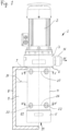
- a submersible centrifugal pump 1 contains a mounting flange 3, an outer tube 4 and an impeller housing 5.
- the mounting flange 3 has a seat 6 with which the submersible centrifugal pump 1 is attached to an upper container wall 7 of a liquid container 8.
- the level of the liquid 9 is in Figure 1 indicated by its surface 10.
- the outer tube 4 extends from the mounting flange 3 to the impeller housing 5.
- the submersible centrifugal pump 1 has a drive shaft 11, see Figures 2 , 12 and 13 , which extends from the impeller housing 5 to the side of the seat surface 6 facing away from the impeller housing 5 and can be designed in one or more parts.
- the submersible centrifugal pump 1 can contain an electric drive motor 2, see Figure 2 , or be driven by an external drive, see Figures 12 and 13 .
- the drive shaft 11 extends from the impeller housing 5 into the drive motor 2.
- the drive motor 2 two bearings 60 and 61 are arranged, in which the drive shaft 11 is cantilevered.
- the impeller housing 5 of a submersible centrifugal pump 1 forms a pump chamber 12 in its interior, in which an impeller 13 is arranged.
- the impeller 13 is attached in a rotationally fixed manner to the lower end of the cantilevered drive shaft 11.
- the submersible centrifugal pump 1 has an inlet 14 at its lower end and an outlet 15 on the installation flange 3.
- the submersible centrifugal pump 1 conveys the liquid 9 from the inlet 14 to the outlet 15 with its rotating impeller 13.
- the outlet 15 is designed as a pressure nozzle connection 16, via which a pipeline (not shown) can be connected to the submersible centrifugal pump 1 in order to guide the pumped liquid 9 to the desired location.
- the outlet 15 and the pressure nozzle connection 16 are located outside the liquid container 8.
- An inner tube 17 is arranged within the outer tube 4 and surrounds the drive shaft 11.
- the impeller housing 5 has an upper wall 19 which separates the pump chamber 12 from the riser channel 18.
- the wall 5 and the installation flange 3 are connected, in particular welded, to both the inner tube 17 and the outer tube 4.
- the impeller housing 5, the inner tube 17, the outer tube 4 and the impeller 13 are made of a material which is resistant to aggressive acids and/or alkalis, for example corrosion-resistant stainless steel or a suitable plastic.
- the riser channel 18 opens at its upper end into a collecting chamber 20 which is located in the installation flange 3 and guides the liquid to the outlet 15.
- the collecting chamber 20 has a smaller flow cross-section on its side opposite the pressure nozzle connection 16, which increases towards the pressure nozzle connection 16, see Figure 2 .
- four channels 21 are arranged, through which the pump chamber 12 is connected to the riser channel 18.
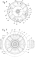
- the channels 21 are evenly distributed along the circumference, see in particular Figure 4 As a result, the forces acting on the impeller 13 in the pump chamber 12 are almost cancelled out along the circumference, so that even a very long drive shaft 11 can be cantilevered on the side of the seat 6 facing away from the impeller housing 5, without excessive transverse forces acting on the lower end of the drive shaft 11.
- the submersible centrifugal pump 1 contains eight cross lines 22 which run through the inner pipe 17, the riser channel 18 and the outer pipe 4 and each connects a space 23 inside the inner pipe 17 with a space 24 outside the outer pipe 4.
- Each of the cross lines 22 is formed by a cross pipe 25 which is welded to the inner pipe 17 and the outer pipe 4.
- both the inner pipe 17 and the outer pipe 4 have a hole.
- Each cross pipe 25 extends through the riser channel 18, whereby no liquid can flow from the cross line 22 into the riser channel 18 or vice versa.
- the cross lines 22 prevent, in a manner known per se, the liquid 9 in the inner space 23 from rising up to the installation flange 3 or even up to the bearing 60.
- cross lines 22 are located in a first plane 26, which is located in the area of the lower end of the outer pipe 4 below the surface 10, see Figures 1 and 4
- Four further cross lines 22 are arranged in a second plane 27, which is arranged in the region of the upper end of the outer tube 4 above the surface 10.
- the two planes 26 and 27 run at right angles to the drive shaft 11.
- Each of the channels 21 extends along a longitudinal extension from the pump chamber 12 to the riser channel 18, which is formed between the inner surface 30 of the outer tube 4 and the outer surface 31 of the inner tube 17.
- Each of the channels 21 has an opening 28 with which the channel 21 opens into the riser channel 18.
- the opening 28 is designed in such a way that it specifies a flow direction 29 which leads along the inner surface 30 of the outer tube 4 between two transverse lines 22. The flow entering the riser channel 18 is thereby directed between the transverse lines 22.
- the flow direction 29 is oriented obliquely to the longitudinal direction of the outer tube 4.
- Each channel 22 has the shape of a spiral section, so that the flow direction 29 has the shape of a spiral which in Figure 6 is indicated by dashed lines.
- the flow direction 29 directs the flow in a spiral shape between two cross lines 22. This minimizes the flow resistance generated by the cross lines 22 in the riser 18.
- the upper wall 19 of the impeller housing 5 is along a circle running through the channels 21 cut and developed into the plane of the drawing. This makes it clear that each channel 21 at its mouth 28 in the riser channel 18 specifies a flow direction 29 which leads between two cross lines 22. Because the inner surface 30 of the outer pipe 4 is a cylindrical surface, the flow emerging from the mouths 28 in the flow direction 29 is deflected in a spiral shape on the curved inner surface 30 and led between two cross lines 22, cf.
- Figure 6 The orifices 28 are each arranged offset to the cross lines 22, see in particular Figure 4 The transverse lines 22 are thus arranged in the flow shadow of the flow exiting from the orifices 28.
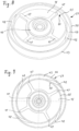
- the impeller 13 comprises a hub 40 and a plate 41, see in particular Figures 8 to 11 .
- the plate 41 extends radially outward from the hub 40 transversely to the drive shaft 11. In the variant shown, the plate 41 is flat. However, it can also extend outward in a conical manner, not shown.
- On the underside of the plate 41 four main blades 42 are arranged, which run curved from the inside to the outside, see in particular Figures 9 , 10 and 11 .
- a cover 43 is arranged which extends along the plate 41.
- the cover 43 has a hole 44 in its center, the circumference of which is larger than the inner circumference of the main blades 42, see Figure 10 .
- a suction pipe 45 is connected to the inner circumference of the cover 43 and extends on the side facing away from the plate 41 to a suction basket 46 at the inlet 14.
- the cover 43 extends outwards beyond the outer circumference of the plate 41 and the outer circumference of the main blades 42, see Figure 8, 9 and 11 .
- the impeller housing 5 On the top of the plate 41, four additional blades 47 are arranged, running in a straight line from the inside to the outside.
- the impeller housing 5 has a surface 48 on the underside of its upper wall 19, which extends parallel to the side of the additional blades 47 facing away from the plate 41.
- the impeller housing 5 also has a circular-cylindrical annular surface 49 located within the pump chamber 12, which faces outwards and is arranged around the Drive shaft 11 runs around.
- the impeller 13 has a circular cylindrical annular surface 50 in the area of its outer circumference, which points inwards and surrounds the annular surface 49 at a distance from the outside. A gap 51 is thereby formed between the annular surfaces 49 and 50.
- the drive shaft 11 leads out of the pump chamber 12 through a hole 52 in the upper wall 19.
- the upper wall 19 surrounds the drive shaft 11 with a gap 53.
- liquid 9 is pumped into the gap 51 by the additional blades 47.
- the impeller 13 has a first ring 55 on the outer circumference of the additional blades 47, on which the ring surface 50 is formed.
- the ring surface 50 surrounds the additional blades 47 on their outer circumference and extends on the side of the additional blades 47 facing away from the plate 41 over a predefined section A along the drive shaft 11.
- the ring 55 also has a jacket surface of a circular cylinder on its outside.
- the ring surfaces 49 and 50 can also extend in the form of jacket surfaces of a cone along the drive shaft 11 and form the gap 51 (not shown).
- the top of the additional blades 47 and the surface 48 opposite it can also have the shape of conical jacket surfaces (not shown).
- the impeller 13 has a second ring 56 which surrounds the main blades 42 on their outer circumference.
- the second ring 56 also surrounds the plate 41 and the first ring 55 at a distance.
- the channels 21 in the wall 19 are arranged distributed over a central circumference 57 of the wall 19, which is smaller than the inner circumference of the ring 56, see Figures 3 and 4 .
- the ring 56 serves to divert the liquid 9 conveyed by the main blades 42 in the direction of the channels 21 and can thereby improve the efficiency of the submersible centrifugal pump 1.
- the impeller 13 can also be designed without the second ring 56, see Figure 11 .
- the impeller 13 is made up of several parts.
- the plate 41 and the additional blades 47 are made in one piece.
- the plate 41 is placed on the hub 40.
- the rings 55 and 56 each have the shape of a pipe section.
- the ring 55 is attached to the plate 41.
- the cover 43, the suction pipe 45 and the main blades 42 are made in one piece.
- the ring 56 is attached to the cover 43.
- the components of the impeller 13 are welded together.
- the Figures 12 and 13 The submersible centrifugal pumps 1 shown in the figure differ from the Figure 2 shown submersible centrifugal pump in the way in which the drive shaft 11 is mounted and driven. Otherwise, the submersible centrifugal pumps 1 of the Figures 12 and 13 identical to the submersible centrifugal pump 1 of the Figure 2 designed, in particular in the area protruding into the liquid container 8 below the seat surface 6, so that in order to avoid repetition, reference is made to the above description.
- the submersible centrifugal pumps 1 of the Figures 12 and 13 do not contain a drive motor 2, instead the drive shaft 11 is led out of the submersible centrifugal pump 1 on the side of the seat 6 opposite the impeller housing 5.
- the drive shaft 11 can be coupled to an external drive via this end 65 protruding from the submersible centrifugal pump 1, for example via a coupling or pulley (not shown). This can be advantageous if the drive is arranged at a greater distance from the submersible centrifugal pump 1, for example if the submersible centrifugal pump 1 is located in an area at risk of explosion and the drive is arranged outside this area.
- a bearing housing 66 is located on the mounting flange 3, which contains two bearings 60 and 61 in which the drive shaft 11 is mounted.
- All bearings 60, 61 of the drive shaft 11 are located outside the liquid container 8. No further bearings are required for the drive shaft 11, in particular no bearings inside the liquid container 8, which exposed to the attack of the aggressive liquid 9. The stability of the submersible centrifugal pump 1 can thereby be extended, especially in dry running when there is no longer any liquid 9 in the impeller housing 5.
- the bearing clearance in the bearings 60, 61 is dimensioned in all variants of the submersible centrifugal pump 1 such that the impeller 13 does not touch the impeller housing 5.
- the effort for the bearing of the drive shaft 11 can be reduced and even a design with a very large distance of the impeller 13 from the seat surface 6 of more than 500 mm or according to Figure 13 with only one single bearing 60.
Landscapes
- Engineering & Computer Science (AREA)
- Mechanical Engineering (AREA)
- General Engineering & Computer Science (AREA)
- Physics & Mathematics (AREA)
- Fluid Mechanics (AREA)
- Structures Of Non-Positive Displacement Pumps (AREA)
Description
- Die Erfindung geht aus von einer Tauchkreiselpumpe mit den im Oberbegriff des Anspruchs 1 angegebenen Merkmalen.
- Eine derartige Tauchkreiselpumpe mit einem Laufrad ist aus der
DE 35 40 025 A1 bekannt. Diese Tauchkreiselpumpe hat einen Antriebsmotor, eine Antriebswelle und ein auf der Antriebswelle sitzendes Laufrad sowie eine Sitzfläche zur Befestigung der Tauchkreiselpumpe derart oben an einem Flüssigkeitsbehälter, dass sich die Antriebswelle von oben nach unten in den Flüssigkeitsbehälter hinein erstreckt. Das Laufrad ist am unteren Ende der Antriebswelle unterhalb der Oberfläche einer in dem Flüssigkeitsbehälter befindlichen Flüssigkeit angeordnet, und zwar in einem einen Pumpenraum ausbildenden Laufradgehäuse. Das Laufrad hat einen Teller, welcher auf seiner Unterseite mehrere Hauptschaufeln zum Pumpen der Flüssigkeit aufweist, wenn das Laufrad im Pumpenraum rotiert. - Aus der
DE 33 28 484 A1 ist eine Tauchkreiselpumpe bekannt, in welcher die Antriebswelle von einem Innenrohr umgeben ist, welches sich von einem Laufradgehäuse nach oben erstreckt. Das Innenrohr ist von einem Außenrohr umgeben, welches mit dem Innenrohr einen ringförmigen Steigkanal für die zu pumpende Flüssigkeit ausbildet. Im Bereich des unteren Endes des Außenrohres verlaufen zwei Querleitungen durch das Innenrohr, den Steigkanal und das Außenrohr hindurch, welche einen Raum innerhalb des Innenrohres mit einem Raum außerhalb des Außenrohres verbinden. Das Laufradgehäuse bildet einen Pumpenraum aus, in welchem ein Laufrad angeordnet ist. Der ringförmige Steigkanal ist an seinem unteren Ende vollständig zu dem Pumpenraum hin geöffnet. - Aus der
DE 32 14 185 A1 ist ferner eine Tauchkreiselpumpe bekannt, welche mehrere Steigrohre aufweist, welche im Querschnitt jeweils die Form eines Ringabschnitts aufweisen, wobei die Ringabschnitte der Steigrohre um die Antriebswelle herum verlaufen. Zwischen den Steigrohren sind Schlitze angeordnet, welche einen die Antriebswelle umgebenden Raum mit einem Raum außerhalb der Steigrohre verbinden und sich im Wesentlichen über die gesamte Länge der Steigrohre erstrecken. - Aus der
EP 0 538 212 A1 ist eine Tauchpumpe bekannt, bei welcher die Pumpe und ein Elektromotor als Einheit in das zu pumpende Medium eingetaucht werden. Der Elektromotor wird direkt von dem umgebenden Medium gekühlt, das gepumpt wird. Das Laufrad weist auf seiner den Hauptschaufeln gegenüberliegenden Seite mehrere Zusatzschaufeln auf, welche an ihrem äußeren Umfang von einem Unterbrechungen aufweisenden Ring umgeben sind. Das Laufrad ist innerhalb der gepumpten Flüssigkeit gelagert. - Aus der
US 4,664,592 A ist ein Laufrad für eine Kreiselpumpe offenbart, welches auf einer den Hauptschaufeln gegenüberliegenden Seite mehrere Zusatzschaufeln aufweist. Die Zusatzschaufeln weisen drei Abschnitte auf. Ein erster Abschnitt der Zusatzschaufeln erstreckt sich unter leichter Krümmung im Wesentlichen in radialer Richtung. Ein zweiter Abschnitt erstreckt sich ringförmig entlang des äußeren Umfangs des Laufrades. Ein dritter Abschnitt ist relativ stark gekrümmt und verbindet den ersten mit dem zweiten Abschnitt. Die ringförmigen Abschnitte der Zusatzschaufeln sind in Umfangsrichtung nicht durchgehend, sondern weisen Durchgänge auf, die sich in radialer Richtung erstrecken. Alle drei Abschnitte der Zusatzschaufeln weisen eine durchgehende Oberfläche aus, welche in einer Ebene liegt, die sich senkrecht zur Rotationsachse des Laufrades erstreckt, sodass die Höhe der Zusatzschaufeln über alle drei Abschnitte konstant ist. - Der Erfindung liegt die Aufgabe zugrunde, eine Tauchkreiselpumpe der eingangs genannten Art hinsichtlich der im Pumpenraum entstehenden Strömung zu verbessern.
- Diese Aufgabe wird gelöst durch eine Tauchkreiselpumpe mit den in Anspruch 1 angegebenen Merkmalen. Vorteilhafte Weiterbildungen der Erfindung sind Gegenstand der Unteransprüche.
- Eine erfindungsgemäße Tauchkreiselpumpe weist eine Antriebswelle, ein mit der Antriebswelle drehfest verbundenes Laufrad und ein Laufradgehäuse auf. Das Laufradgehäuse bildet einen Pumpenraum aus, in welchem das Laufrad angeordnet ist. Die Tauchkreiselpumpe hat eine Sitzfläche zur Befestigung der Tauchkreiselpumpe derart oben an einem Flüssigkeitsbehälter, dass sich die Antriebswelle von oben nach unten in den Flüssigkeitsbehälter hinein erstreckt. Die Tauchkreiselpumpe kann mit ihrer Sitzfläche an einer oberen Behälterwand des Flüssigkeitsbehälters befestigt werden. Im Betrieb kommt das Laufrad im Innern des Flüssigkeitsbehälters unter der Oberfläche einer darin befindlichen Flüssigkeit zu liegen. Das Laufradgehäuse weist eine Ringfläche, insbesondere eine Zylindermantelfläche, auf, welche innerhalb des Pumpenraums um die Antriebswelle herum, insbesondere koaxial hierzu, verläuft. Die innerhalb des Pumpenraums liegende Ringfläche des Laufradgehäuses weist nach außen. Das Laufrad weist, insbesondere im Bereich seines äußeren Umfangs, eine nach innen weisende Ringfläche, insbesondere eine Zylindermantelfläche, auf, welche die Ringfläche des Laufradgehäuses außen umgibt.
- Das Laufrad kann einen Teller haben, welcher auf einer seiner Seiten mehrerer Hauptschaufeln und auf einer den Hauptschaufeln gegenüberliegenden Seite mehrere Zusatzschaufeln aufweist. Die Hauptschaufeln dienen zum eigentlichen Pumpen der Flüssigkeit. Die Zusatzschaufeln können sich auf der der Sitzfläche zugewandten Seite des Laufrades, welche im Betrieb seine nach oben gewandte Seite ist, befinden. Das Laufrad kann eine Nabe aufweisen, mit welcher es auf der Antriebswelle, insbesondere auf einem ihrer Enden, befestigt werden kann. Der Teller kann sich von der Antriebswelle bzw. der Nabe nach außen erstrecken. Der Teller kann sich radial zwischen einem kleinen Umfang und einem großen Umfang am Laufrad erstrecken. Der Teller kann dabei quer oder schräg zur Antriebswelle verlaufen, also eben oder kegelig sein. Die Hauptschaufeln erstrecken sich entlang des Tellers von einem kleinen Umfang zu einem großen Umfang des Laufrades. Insbesondere haben die Hauptschaufeln eine Krümmung, welche in einer Ansicht entlang der Antriebswelle erkennbar ist. Die Hauptschaufeln und die Zusatzschaufeln erstrecken sich auf gegenüberliegenden Seiten entlang des Tellers und sind jeweils mit diesem verbunden. Jede der Hauptschaufeln und jede der Zusatzschaufeln erstreckt sich ausgehend von dem Teller über eine vordefinierte Höhe von diesem weg. Das Laufrad kann am äußeren Umfang der Zusatzschaufeln einen Ring mit einer nach innen weisenden Ringfläche aufweisen, welche auf einem dem Teller abgewandten Seite der Zusatzschaufeln angeordnet ist und/oder die Zusatzschaufeln an ihrem äußeren Umfang umgibt. Die Ringfläche kann insbesondere zur Nabe weisen.
- Durch die in Anspruch 1 angegebenen Merkmale der erfindungsgemäßen Tauchkreiselpumpe wird jeweils für sich allein genommen bereits eine Verbesserung der Strömungsverhältisse der Flüssigkeit im Pumpenraum erreicht. Die Strömung im Pumpenraum kann durch eine Kombination der erfindungsgemäßen Tauchkreiselpumpe mit einem Laufrad, das die in Anspruch 2 angegebenen Merkmale aufweist, besonders deutlich verbessert werden. Die verbesserte Strömung im Pumpenraum hat insbesondere eine selbstzentrierende Wirkung auf das Laufrad. Die durch die Rotation des Laufrades im Betrieb entstehenden Strömungskräfte können dadurch zur Zentrierung des Laufrades im Laufradgehäuse beitragen, sodass die vom Laufrad auf die Antriebswelle übertragenen Radialkräfte geringer sind. Die aus den Strömungskräften resultierende Belastung der Antriebswellenlagerung lässt sich dadurch stark verringern. Die Lebensdauer der Tauchkreiselpumpe kann dadurch erhöht werden. Außerdem kann auf eine innerhalb des Flüssigkeitsbehälters angeordnete Lagerung der Antriebswelle verzichtet werden.
- Die Ringfläche des Laufradgehäuses weist einen kleineren Umfang als die Ringfläche des Laufrades auf. Die Ringfläche des Laufrades kann die Ringfläche des Laufradgehäuses derart in einem Abstand umgeben, dass zwischen beiden Ringflächen ein Spalt ausgebildet wird, welcher entlang des Umfangs des Laufrades verläuft. Die Ringfläche des Laufrades und die Ringfläche des Laufradgehäuses können sich koaxial zu der Antriebwelle erstrecken, insbesondere über einen vordefinierten Abschnitt. Die Ringfläche des Laufrades und die Ringfläche des Laufradgehäuses können jeweils als Zylindermantelfläche, insbesondere als Mantelfläche eines Kreiszylinders, oder als Kegelfläche ausgebildet sein. Jede der beiden Ringflächen kann entlang ihres Umfangs unterbrechungsfrei ausgeführt sein.
- Die Antriebswelle ist durch ein Loch oben im Laufradgehäuse, insbesondere in dessen oberer Wand, nach oben aus dem Pumpenraum herausgeführt. Derartige Tauchkreiselpumpen sind zum Pumpen von aggressiven Flüssigkeiten, beispielsweise Säuren oder Laugen, bestimmt. Es können auch abrasive Partikel in der Flüssigkeit enthalten sein. Deshalb werden die Antriebswelle berührende Dichtungen vermieden, sodass ein Ringspalt zwischen Antriebswelle und Laufradgehäuse vorhanden ist. Bei entsprechendem Druck im Pumpenraum kann ein Druckgefälle an diesem Ringspalt entstehen. Je nach Betriebszustand der Tauchkreiselpumpe kann der Druck im Pumpenraum höher als im Flüssigkeitsbehälter sein, sodass Flüssigkeit in Form einer sogenannten Bypass-Strömung durch diesen Ringspalt aus dem Laufradgehäuse austreten kann. Die Bypass-Strömung ist eine Verlustströmung, welche die Menge der von der Tauchkreiselpumpe aus dem Flüssigkeitsbehälter herausgepumpten Flüssigkeit verringert. Es können aber auch Betriebszustände der Tauchkreiselpumpe auftreten, in denen der Druck im Pumpenraum geringer als im Flüssigkeitsbehälter ist, sodass es zu einem Einsaugen von Flüssigkeit durch den Ringspalt zwischen Antriebswelle und Laufradgehäuse kommen kann. Ein solches Einsaugen kann unerwünscht sein, wenn der Flüssigkeitsstand im Flüssigkeitsbehälter niedrig ist, sodass die Gefahr besteht, dass Luft durch diesen Ringspalt in den Pumpenraum eingesaugt wird. Insbesondere bei schaumbildenden Flüssigkeiten kann dies sehr nachteilig sein. Dadurch, dass erfindungsgemäß die Ringfläche des Laufrades und die Ringfläche des Laufradgehäuses einander gegenüberliegen, kann dieses Druckgefälle über einen breiten Betriebsbereich der Tauchkreiselpumpe verringert werden. Dies gilt insbesondere in Kombination mit den Zusatzschaufeln, welche im Betrieb für einen Druckausgleich an dem Spalt zwischen der Ringfläche des Laufrades und der Ringfläche des Laufradgehäuses sorgen, und dadurch zu einer wesentlichen Verkleinerung des Druckgefälles führen können. Dadurch lässt sich sowohl eine Bypass-Strömung als auch ein Einsaugen von Flüssigkeit durch den Ringspalt zwischen Antriebswelle und Laufradgehäuse über einen breiten Betriebsbereich der Tauchkreiselpumpe vermeiden.
- In weiterer Ausgestaltung der Erfindung kann das Laufradgehäuse eine obere Wand mit einer nach unten weisenden Oberfläche haben, welche sich entlang der Oberseite des Laufrades erstreckt. Die Oberfläche an der oberen Wand kann an die Ringfläche des Laufradgehäuses angrenzen. Die Oberfläche an der oberen Wand des Laufradgehäuses kann sich insbesondere parallel oder äquidistant zu der dem Teller abgewandten Seite der Zusatzschaufeln erstrecken. Hierdurch wird die Bypass-Strömung weiter verringert. Die Zusatzschaufeln können geradlinig radial von innen nach außen verlaufen.
- In weiterer Ausgestaltung kann der Ring des Laufrades die Zusatzschaufeln an ihrem äußeren Umfang berühren oder mit Abstand umgeben. Das Laufrad kann auf einer dem Teller abgewandten Seite der Hauptschaufeln einen Deckel aufweisen. Der Deckel kann sich über den äußeren Umfang des Tellers und/oder den äußeren Umfang der Hauptschaufeln hinaus nach außen erstrecken. Die Hauptschaufeln können sich über den äußeren Umfang des Tellers hinaus erstrecken. Zwischen zwei der Hauptschaufeln, dem Teller und dem Deckel bildet sich ein von innen nach außen verlaufender Kanal, welcher entlang seines gesamten Umfangs geschlossen ist. Durch die Rotation des Laufrades wird im Betrieb Flüssigkeit durch diesen Kanal des Laufrades radial nach außen gefördert. Der Deckel kann in seiner Mitte, also koaxial zur Nabe bzw. Antriebswelle ein Loch aufweisen, dessen Umfang größer als der innere Umfang der Hauptschaufeln ist. Am inneren Umfang des Deckels kann sich ein Saugrohr anschließen, welches sich von Deckel zu der dem Teller abgewandten Seite erstreckt.
- In weiterer Ausgestaltung kann das Laufrad zwei Ringe aufweisen. Ein erster der Ringe kann auf einer dem Teller abgewandten Seite der Zusatzschaufeln angeordnet sein und/oder die Zusatzschaufeln an ihrem äußeren Umfang umgeben. Ein zweiter der Ringe kann den Teller in einem Abstand und/oder die Hauptschaufeln an ihrem äußeren Umfang umgeben. Der erste Ring kann die nach innen weisende Ringfläche aufweisen, welche die nach außen weisende Ringfläche des Laufradgehäuses umgibt. Der zweite Ring kann sich koaxial zu der Antriebswelle erstrecken, insbesondere über einen vordefinierten Abschnitt. Der zweite Ring kann sich auf der den Zusatzschaufeln zugewandten Seite der Hauptschaufeln befinden. Dabei kann der zweite Ring auch die Zusatzschaufeln und/oder den ersten Ring in einem Abstand umgeben. Jeder der Ringe kann an seinem inneren Umfang und/oder an seinem äußeren Umfang jeweils eine Zylindermantelfläche, insbesondere eine Mantelfläche eines Kreiszylinders, aufweisen. Der zweite Ring kann die Umlenkung der von den Hauptschaufeln radial nach außen geförderten Flüssigkeit in eine entlang der Antriebswelle verlaufende Strömungsrichtung verbessern. Dadurch kann der Wirkungsgrad der Tauchkreiselpumpe verbessert werden.
- Das Laufrad kann einstückig oder aus mehreren Teilen gefertigt sein. Jeder Bestandteil des Laufrades, insbesondere die Nabe, der Teller, die Hauptschaufeln, die Zusatzschaufeln, der Deckel und der wenigstens eine Ring, können alle oder nur teilweise einteilig miteinander oder mehrteilig gefertigt werden. Insbesondere kann der erste Ring und/oder zweite Ring in Form eines Rohrabschnitts ausgebildet sein, welcher an dem Laufrad befestigt, insbesondere mit diesem verschweißt, ist.
- In weiterer Ausgestaltung der Erfindung kann die Antriebswelle von einem Innenrohr umgeben sein. Die Antriebswelle und das Innenrohr können von einem Außenrohr umgeben sein. Das Außenrohr und das Innenrohr erstrecken sich jeweils zwischen dem Laufradgehäuse und der Sitzfläche. Eine Innenfläche des Außenrohres bildet mit einer Außenfläche des Innenrohres einen ringförmigen Steigkanal für die zu pumpende Flüssigkeit aus. Das Innenrohr und das Außenrohr bilden somit ein doppelwandiges Steigrohr, zwischen dessen Wandungen der ringförmige Steigkanal ausgebildet ist. Durch das Innenrohr, den Steigkanal und das Außenrohr hindurch verlaufen mehrere Querleitungen, welche jeweils einen Raum innerhalb des Innenrohres mit einem Raum außerhalb des Außenrohres verbinden. Derartige Querleitungen und ihre Funktion sind dem Fachmann bekannt, beispielsweise aus der
DE 33 28 484 A1 . Das Außenrohr und das Innenrohr können jeweils mit der oberen Wand des Laufradgehäuses verbunden, insbesondere verschweißt, sein. In der oberen Wand des Laufradgehäuses sind mehrere Kanäle angeordnet, durch welche der Pumpenraum mit dem Steigkanal in Verbindung steht. Die zu pumpende Flüssigkeit kann aus dem Pumpenraum durch diese Kanäle in den Steigkanal eintreten. Jeder der Kanäle hat eine Längserstreckung vom Pumpenraum zum Steigkanal und eine Mündung in den Steigkanal. An seiner Mündung in den Steigkanal gibt jeder Kanal eine Strömungsrichtung vor, welche an der Innenfläche des Außenrohres entlang zwischen zwei der Querleitungen hindurchführt. Die vorgegebene Strömungsrichtung und/oder die Längsrichtung jedes Kanals kann schräg zur Längsrichtung des Außenrohres bzw. der Antriebswelle orientiert sein. Die vorgegebene Strömungsrichtung kann windschief zur Antriebswelle verlaufen. Als windschief werden zwei Linien bezeichnet, welche nicht parallel zueinander im Raum verlaufen und sich nicht schneiden. Jeder der Kanäle kann insbesondere die Form eines Wendelabschnitts aufweisen. Die Fortsetzung des Wendelabschnittes führt zwischen zwei der Querleitungen hindurch. - Durch die beschriebene Anordnung der Eintrittskanäle in der oberen Wand des Laufradgehäuses wird die zu pumpende Flüssigkeit gezielt in den Steigkanal hinein gelenkt. Die Strömung kann dadurch zwischen zwei Querleitungen hindurch gelenkt werden. Dadurch befindet sich jede der Querleitungen gewissermaßen im Strömungsschatten der Hauptströmung, welche durch die Kanäle aus dem Pumpenraum in den Steigkanal eintritt. Unkontrollierte und starke Verluste verursachende Verwirbelungen im Steigkanal lassen sich hierdurch erheblich verringern. Im Gegensatz zu der aus der
DE 33 28 484 A1 bekannten Ausgestaltung, bei welcher die in den ringförmigen Steigkanal eintretende Flüssigkeit unkontrolliert auf die Querleitungen trifft, können Strömungsverluste verringert und der Wirkungsgrad der Tauchkreiselpumpe erhöht werden. - In weiterer Ausgestaltung kann die Mündung eines jeden der Kanäle entlang des Umfangs versetzt zu den Querleitungen angeordnet sein. Die Mitte jeder Mündung liegt dabei an einer anderen Umfangsposition als die Mitte jeder Querleitung. Die Kanäle können entlang des Umfangs gleichmäßig voneinander beabstandet sein. Alle Kanäle können in dieselbe Form haben. Jede der Querleitungen kann durch ein Querrohr gebildet werden, welches am Innenrohr und am Außenrohr angesetzt, insbesondere angeschweißt, ist und sich durch den Steigkanal hindurch erstreckt. Das Innenrohr und das Außenrohr weisen hierfür jeweils ein Loch auf. Mehrere der Querleitungen können in einer quer, insbesondere rechtwinklig, zur Antriebswelle verlaufenden Ebene liegen. Im Bereich des unteren Endes des Außenrohres kann eine erste Ebene mit mehreren Querleitungen angeordnet sein. Die in der ersten Ebene angeordneten Querleitungen befinden sich im Betrieb unterhalb der Oberfläche der Flüssigkeit im Flüssigkeitsbehälter. Die Anzahl der in der ersten Ebene angeordneten Querleitungen kann insbesondere mit der Anzahl der in der oberen Wand des Laufradgehäuses angeordneten Kanäle übereinstimmen. Oberhalb der ersten Ebene kann eine zweite Ebene mit mehreren Querleitungen angeordnet sein, welche sich insbesondere oberhalb der Oberfläche der Flüssigkeit im Flüssigkeitsbehälter befindet. Die zweite Ebene kann im Bereich des oberen Endes des Außenrohres angeordnet sein. Die Anzahl der Querleitungen in der ersten Ebene und in der zweiten Ebene kann übereinstimmen. Die Querleitungen in den beiden Ebenen können bei Betrachtung entlang der Antriebswelle hintereinander angeordnet sein.
- In weiterer Ausgestaltung können die Kanäle in der oberen Wand des Laufradgehäuses auf einem mittleren Umfang der oberen Wand angeordnet sein, welcher größer als der äußere Umfang des ersten Ringes und kleiner als der innere Umfang des zweiten Ringes ist, insbesondere mit dem mittleren Umfang zwischen den beiden Ringen übereinstimmt. Hierdurch kann die vom Laufrad kommende Flüssigkeit in vorteilhafter Weise in die Kanäle in der oberen Wand des Laufradgehäuses strömen und der Wirkungsgrad der Tauchkreiselpumpe weiter verbessert werden.
- In weiterer Ausgestaltung kann die Lagerung der Antriebswelle oberhalb der Sitzfläche zur Befestigung der Tauchkreiselpumpe angeordnet sein. Erfindungsgemäss ist die Antriebwelle ausschließlich auf der dem Laufradgehäuse abgewandten Seite der Sitzfläche gelagert. Dadurch befinden sich sämtliche Lager für die Antriebswelle außerhalb des Flüssigkeitsbehälters und kommen nicht mit der zu pumpenden Flüssigkeit in Kontakt. Durch die selbstzentrierende Wirkung der Strömung im Pumpenraum auf das Laufrad können sich erfindungsgemäße Tauchkreiselpumpen sehr weit nach unten in den Flüssigkeitsbehälter hinein erstrecken, ohne dass innerhalb des Flüssigkeitsbehälters bzw. unterhalb der Oberfläche der Flüssigkeit Lagerungen der Antriebswelle erforderlich sind. Das Laufrad kann mehr als 500 mm, insbesondere 600 mm bis 800 mm, Abstand von der Sitzfläche aufweisen. Die Lagerung kann aus einem einzigen Lager, insbesondere Kugellager, oder aus mehr als einem Lager bestehen. Das Lagerspiel in der Lagerung der Antriebswelle kann derart bemessen werden, dass das Laufrad weder im Betrieb noch im Ruhezustand mit dem Laufradgehäuse in Kontakt kommt. Dadurch kann eine dauerhafte Trockenlauffähigkeit der erfindungsgemäßen Tauchkreiselpumpe gewährleistet werden.
- In weiterer Ausgestaltung kann die Antriebswelle der Tauchkreiselpumpe mit einem Antrieb gekoppelt sein, beispielsweise über eine Kupplung oder einen Antriebsriemen. Die Tauchkreiselpumpe kann auch einen mit der Antriebswelle gekoppelten Antriebsmotor enthalten, welcher auf der dem Laufradgehäuse abgewandten Seite der Sitzfläche angeordnet ist. Im Betrieb ist der Antrieb dadurch außerhalb des Flüssigkeitsbehälters angeordnet. Die Sitzfläche kann sich am Antriebsmotor oder an einem Einbauflansch befinden. Das Innenrohr und das Außenrohr können sich jeweils vom Einbauflansch zum Laufradgehäuse erstrecken. Das Laufradgehäuse wird dadurch vom Innenrohr bzw. vom Außenrohr getragen. Der Einbauflansch kann einen Druckstutzenanschluss aufweisen, welcher sich auf der dem Laufradgehäuse abgewandten Seite der Sitzfläche, also im Betrieb außerhalb des Flüssigkeitsbehälters, befindet. Der Einbauflansch dient zum Hindurchführen der zu pumpenden Flüssigkeit durch die obere Behälterwand. Der Steigkanal steht über den Einbauflansch mit dem Druckstutzenanschluss in Verbindung. Die Antriebswelle kann ausschließlich im Antriebsmotor mit zwei Lagern gelagert sein, wobei das Laufrad an dem dem Antriebsmotor abgewandten Ende der Antriebswelle befestigt ist. Das Laufrad ist dabei an dem freien Ende der Antriebswelle angeordnet ("fliegende Lagerung").
- Weitere Einzelheiten und Vorteile der Erfindung werden an Ausführungsbeispielen der Erfindung unter Bezugnahme auf die beigefügten Zeichnungen erläutert. Gleiche und einander entsprechende Komponenten sind darin mit übereinstimmenden Bezugszahlen versehen. Es zeigen:
- Figur 1
- eine Seitenansicht einer erfindungsgemäßen Tauchkreiselpumpe,
- Figur 2
- einen Längsschnitt der Tauchkreiselpumpe der
Figur 1 , - Figur 3
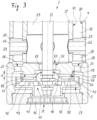
- eine vergrößerte Ansicht des unteren Endes der Tauchkreiselpumpe der
Figur 2 , - Figur 4
- einen Querschnitt durch die Tauchkreiselpumpe entlang der Schnittfläche IV-IV der
Figur 1 , - Figur 5
- einen Querschnitt durch die Tauchkreiselpumpe entlang der Schnittfläche V-V der
Figur 1 , - Figur 6
- eine perspektivische Ansicht auf das untere Ende der Tauchkreiselpumpe der
Figur 1 bei abgenommenem Außenrohr, - Figur 7
- eine schematische Ansicht zur Verdeutlichung der Strömung im unteren Bereich der Tauchkreiselpumpe,
- Figur 8
- eine perspektivische Ansicht eines erfindungsgemäßen Laufrades,
- Figur 9
- das Laufrad der
Figur 8 in einer Ansicht von oben, - Figur 10
- das Laufrad der
Figur 8 in einer Ansicht von unten, - Figur 11
- eine perspektivische Ansicht einer Variante eines erfindungsgemäßen Laufrades,
- Figur 12
- eine Variante einer erfindungsgemäßen Tauchkreiselpumpe in einer Darstelllung entsprechend der
Figur 2 , - Figur 13
- eine weitere Variante einer erfindungsgemäßen Tauchkreiselpumpe in einer Darstelllung entsprechend der
Figur 2 . - Eine erfindungsgemäße Tauchkreiselpumpe 1 enthält einen Einbauflansch 3, ein Außenrohr 4 und ein Laufradgehäuse 5. Der Einbauflansch 3 hat eine Sitzfläche 6, mit welcher die Tauchkreiselpumpe1 auf einer oberen Behälterwand 7 eines Flüssigkeitsbehälters 8 befestigt wird. In dem Flüssigkeitsbehälter 8 befindet sich ein eine zu pumpende Flüssigkeit 9. Der Stand der Flüssigkeit 9 ist in
Figur 1 durch ihre Oberfläche 10 angedeutet. Das Außenrohr 4 erstreckt sich vom Einbauflansch 3 zum Laufradgehäuse 5. - Die erfindungsgemäße Tauchkreiselpumpe 1 hat eine Antriebswelle 11, siehe
Figuren 2 ,12 und13 , welche sich vom Laufradgehäuse 5 bis auf die dem Laufradgehäuse 5 abgewandte Seite der Sitzfläche 6 erstreckt und ein- oder mehrteilig ausgeführt sein kann. Die Tauchkreiselpumpe 1 kann einen elektrischen Antriebsmotor 2 enthalten, sieheFigur 2 , oder durch einen externen Antrieb antreibbar sein, sieheFiguren 12 und13 . - Bei der in
Figur 2 dargestellten Tauchkreiselpumpe 1 erstreckt sich die Antriebswelle 11 vom Laufradgehäuse 5 bis in den Antriebsmotor 2. Im Antriebsmotor 2 sind zwei Lager 60 und 61 angeordnet, in welchen die Antriebswelle 11 fliegend gelagert ist. - Das Laufradgehäuse 5 einer erfindungsgemäßen Tauchkreiselpumpe 1 bildet einen Pumpenraum 12 in seinem Inneren aus, in welchem ein Laufrad 13 angeordnet ist. Das Laufrad 13 ist drehfest auf dem unteren Ende der fliegend gelagerten Antriebswelle 11 befestigt. Die Tauchkreiselpumpe 1 hat einen Einlass 14 an ihrem unteren Ende und einen Auslass 15 am Einbauflansch 3. Die Tauchkreiselpumpe 1 fördert mit ihrem rotierenden Laufrad 13 die Flüssigkeit 9 von dem Einlass 14 zu dem Auslass 15. Der Auslass 15 ist als Druckstutzenanschluss 16 ausgestaltet, über welchen eine nicht dargestellte Rohrleitung an die Tauchkreiselpumpe 1 anschließbar ist, um die gepumpte Flüssigkeit 9 zu dem gewünschten Ort zu leiten. Der Auslass 15 und der Druckstutzenanschluss 16 befinden sich außerhalb des Flüssigkeitsbehälters 8. Innerhalb des Außenrohres 4 ist ein Innenrohr 17 angeordnet, welches die Antriebswelle 11 umgibt. Das Innenrohr 17 bildet zusammen mit dem Außenrohr 4 einen ringförmigen Steigkanal 18 für die zu pumpende Flüssigkeit 9 aus. Das Laufradgehäuse 5 weist eine obere Wand 19 auf, welche den Pumpenraum 12 von dem Steigkanal 18 abgrenzt. Die Wand 5 und der Einbauflansch 3 sind sowohl mit dem Innenrohr 17 als auch mit dem Außenrohr 4 verbunden, insbesondere verschweißt. Das Laufradgehäuse 5, das Innenrohr 17, das Außenrohr 4 und das Laufrad 13 bestehen aus einem Material, welches gegen aggressive Säuren und/oder Laugen beständig ist, beispielsweise aus korrosionsbeständigem Edelstahl oder einem geeigneten Kunststoff. Der Steigkanal 18 mündet an seinem oberen Ende in einen Sammelraum 20, welcher sich im Einbauflansch 3 befindet und die Flüssigkeit zu dem Auslass 15 leitet. Der Sammelraum 20 weist auf seiner dem Druckstutzenanschluss 16 gegenüberliegenden Seite einen kleineren Strömungsquerschnitt auf, welcher sich zum Druckstutzenanschluss 16 hin vergrößert, siehe
Figur 2 . In der oberen Wand 19 sind vier Kanäle 21 angeordnet, durch welche der Pumpenraum 12 mit dem Steigkanal 18 in Verbindung steht. Die Kanäle 21 sind gleichmäßig entlang des Umfangs verteilt angeordnet, siehe insbesondereFigur 4 . Dadurch sind die im Pumpenraum 12 auf das Laufrad 13 wirkenden Kräfte entlang des Umfangs nahezu aufgehoben, sodass auch eine sehr lange Antriebswelle 11 auf der dem Laufradgehäuse 5 abgewandten Seite der Sitzfläche 6 fliegend gelagert werden kann, ohne dass zu große Querkräfte auf das untere Ende der Antriebswelle 11 wirken. - Die Tauchkreiselpumpe 1 enthält acht Querleitungen 22, welche durch das Innenrohr 17, den Steigkanal 18 und das Außenrohr 4 hindurch verlaufen und jeweils einen Raum 23 innerhalb des Innenrohrs 17 mit einem Raum 24 außerhalb des Außenrohres 4 verbinden. Jede der Querleitungen 22 ist durch ein Querrohr 25 gebildet, welches am Innenrohr 17 und am Außenrohr 4 angeschweißt ist. Für jede Querleitung 22 hat sowohl das Innenrohr 17 als auch das Außenrohr 4 ein Loch. Jedes Querrohr 25 erstreckt sich durch den Steigkanal 18 hindurch, wobei keine Flüssigkeit aus der Querleitung 22 in den Steigkanal 18 hinein oder umgekehrt fließen kann. Die Querleitungen 22 verhindern in an sich bekannter Weise, dass die Flüssigkeit 9 in dem inneren Raum 23 bis zu dem Einbauflansch 3 oder gar bis zu dem Lager 60 aufsteigt. Vier Querleitungen 22 liegen in einer ersten Ebene 26, welche sich im Bereich des unteren Endes des Außenrohres 4 unterhalb der Oberfläche 10 befindet, siehe
Figuren 1 und4 . Vier weitere Querleitungen 22 sind in einer zweiten Ebene 27 angeordnet, welche im Bereich des oberen Endes des Außenrohres 4 über der Oberfläche 10 angeordnet ist. Die beiden Ebenen 26 und 27 verlaufen rechtwinklig zur Antriebswelle 11. - Jeder der Kanäle 21 erstreckt sich entlang einer Längserstreckung vom Pumpenraum 12 zum Steigkanal 18, welcher zwischen der Innenfläche 30 des Außenrohres 4 und der Außenfläche 31 des Innenrohres 17 gebildet ist. Jeder der Kanäle 21 hat eine Mündung 28, mit welcher der Kanal 21 in den Steigkanal 18 einmündet. Die Mündung 28 ist derart gestaltet, dass sie eine Strömungsrichtung 29 vorgibt, welche an der Innenfläche 30 des Außenrohres 4 entlang zwischen zwei Querleitungen 22 hindurchführt. Die in den Steigkanal 18 eintretende Strömung wird dadurch zwischen den Querleitungen 22 hindurch gelenkt. Die Strömungsrichtung 29 ist schräg zur Längsrichtung des Außenrohres 4 orientiert. Jeder Kanal 22 hat die Form eines Wendelabschnitts, sodass die Strömungsrichtung 29 jeweils die Form einer Wendel hat, welche in
Figur 6 gestrichelt angedeutet ist. Durch die Strömungsrichtung 29 wird die Strömung wendelförmig zwischen zwei Querleitungen 22 hindurchgelenkt. Dadurch wird der von den Querleitungen 22 im Steigkanal 18 erzeugte Strömungswiderstand minimiert. In der schematischen Darstellung derFigur 7 ist die obere Wand 19 des Laufradgehäuses 5 entlang eines durch die Kanäle 21 verlaufenden Kreises geschnitten und in die Zeichenebene abgewickelt. Hierdurch wird deutlich, dass jeder Kanal 21 an seiner Mündung 28 in den Steigkanal 18 eine Strömungsrichtung 29 vorgibt, welche zwischen zwei Querleitungen 22 hindurchführt. Dadurch, dass die Innenfläche 30 des Außenrohres 4 eine Zylindermantelfläche ist, wird die aus den Mündungen 28 in der Strömungsrichtung 29 austretende Strömung an der gekrümmten Innenfläche 30 wendelförmig abgelenkt und zwischen zwei Querleitungen 22 hindurchgeführt, vgl.Figur 6 . Die Mündungen 28 sind jeweils versetzt zu den Querleitungen 22 angeordnet, siehe insbesondereFigur 4 . Die Querleitungen 22 sind somit im Strömungsschatten der aus den Mündungen 28 austretenden Strömung angeordnet. - Das Laufrad 13 enthält eine Nabe 40 und einen Teller 41, siehe insbesondere
Figuren 8 bis 11 . Der Teller 41 erstreckt sich quer zur Antriebswelle 11 von der Nabe 40 radial nach außen. In der dargestellten Variante ist der Teller 41 eben. Er kann sich in nicht dargestellter Weise aber auch kegelförmig nach außen erstrecken. Auf der Unterseite des Tellers 41 sind vier Hauptschaufeln 42 angeordnet, welche gekrümmt von innen nach außen verlaufen, siehe insbesondereFiguren 9 ,10 und 11 . Auf einer dem Teller 41 abgewandten Seite der Hauptschaufeln 42 ist ein Deckel 43 angeordnet, welcher sich entlang des Tellers 41 erstreckt. Der Deckel 43 weist in seiner Mitte ein Loch 44 auf, dessen Umfang größer als der innere Umfang der Hauptschaufeln 42 ist, sieheFigur 10 . Am inneren Umfang des Deckels 43 schließt sich ein Saugrohr 45 an, welches sich auf der dem Teller 41 abgewandten Seite bis zu einem Saugkorb 46 am Einlass 14 erstreckt. Der Deckel 43 erstreckt sich über den äußeren Umfang des Tellers 41 und den äußeren Umfang der Hauptschaufeln 42 hinaus nach außen, sieheFigur 8, 9 und11 . - Auf der Oberseite des Tellers 41 sind vier geradlinig von innen nach außen verlaufende Zusatzschaufeln 47 angeordnet. Das Laufradgehäuse 5 hat an der Unterseite seiner oberen Wand 19 eine Oberfläche 48, welche sich parallel zu der dem Teller 41 abgewandten Seite der Zusatzschaufeln 47 erstreckt. Das Laufradgehäuse 5 hat ferner eine innerhalb des Pumpenraumes 12 liegende kreiszylindrische Ringfläche 49, welche nach außen weist und um die Antriebswelle 11 herum verläuft. Das Laufrad 13 hat im Bereich seines äußeren Umfangs eine kreiszylindrische Ringfläche 50, welche nach innen weist und die Ringfläche 49 in einem Abstand außen umgibt. Zwischen den Ringflächen 49 und 50 wird dadurch ein Spalt 51 gebildet. Hierdurch werden die Strömungsverhältnisse im Pumpenraum 12 verbessert und die Radialkräfte auf die Antriebswelle 11 vermindert. Die Antriebswelle 11 ist durch ein Loch 52 in der oberen Wand 19 aus dem Pumpenraum 12 herausgeführt. Die obere Wand 19 umgibt die Antriebswelle 11 mit einem Spalt 53. Im Betrieb der Tauchkreiselpumpe 1 wird durch die Zusatzschaufeln 47 Flüssigkeit 9 in den Spalt 51 gefördert. Dadurch wird insgesamt eine Bypass-Strömung vermindert, welche durch den Spalt 53 aus dem Laufradgehäuse 5 austritt und ungenutzt über den Raum 23 und die Querleitungen 22 in den Flüssigkeitsbehälter 8 zurückströmt. Das Laufrad 13 weist am äußeren Umfang der Zusatzschaufeln 47 einen ersten Ring 55 auf, an welchem die Ringfläche 50 ausgebildet ist. Die Ringfläche 50 umgibt die Zusatzschaufeln 47 an ihrem äußeren Umfang und erstreckt sich auf der dem Teller 41 abgewandten Seite der Zusatzschaufeln 47 über einen vordefinierten Abschnitt A entlang der Antriebswelle 11. Der Ring 55 weist auf seiner Außenseite ebenfalls eine Mantelfläche eines Kreiszylinders auf. Alternativ können sich die Ringflächen 49 und 50 in nicht dargestellter Weise auch in Form von Mantelflächen eines Kegels entlang der Antriebswelle 11 erstrecken und den Spalt 51 bilden. Auch die Oberseite der Zusatzschaufeln 47 und die dieser gegenüberliegende Oberfläche 48 können in nicht dargestellter Weise die Form von Kegelmantelflächen aufweisen.
- Das Laufrad 13 weist einen zweiten Ring 56 auf, welcher die Hauptschaufeln 42 an ihrem äußeren Umfang umgibt. Der zweite Ring 56 umgibt ferner den Teller 41 und den ersten Ring 55 in einem Abstand. Die Kanäle 21 in der Wand 19 sind auf einem mittleren Umfang 57 der Wand 19 verteilt angeordnet, welcher kleiner als der innere Umfang des Ringes 56 ist, siehe
Figuren 3 und4 . Der Ring 56 dient zum Umlenken der von den Hauptschaufeln 42 geförderten Flüssigkeit 9 in Richtung der Kanäle 21 und kann dadurch den Wirkungsgrad der Tauchkreiselpumpe 1 verbessern. Das Laufrad 13 kann auch ohne den zweiten Ring 56 ausgeführt werden, sieheFigur 11 . - Das Laufrad 13 ist mehrteilig ausgebildet. Der Teller 41 und die Zusatzschaufeln 47 sind einstückig ausgebildet. Der Teller 41 ist auf die Nabe 40 aufgesetzt. Die Ringe 55 und 56 haben jeweils die Form eines Rohrabschnitts. Der Ring 55 ist an dem Teller 41 befestigt. Der Deckel 43, das Saugrohr 45 und die Hauptschaufeln 42 sind einstückig miteinander gefertigt. Der Ring 56 ist an dem Deckel 43 befestigt. Die Bestandteile des Laufrades 13 sind miteinander verschweißt.
- Die in den
Figuren 12 und13 dargestellten Tauchkreiselpumpen 1 unterscheiden sich von der inFigur 2 dargestellten Tauchkreiselpumpe in der Art und Weise wie die Antriebswelle 11 gelagert und angetrieben ist. Ansonsten sind die Tauchkreiselpumpen 1 derFiguren 12 und13 identisch zu der Tauchkreiselpumpe 1 derFigur 2 ausgebildet, insbesondere in dem in den Flüssigkeitsbehälter 8 hineinragenden Bereich unterhalb der Sitzfläche 6, sodass zur Vermeidung von Wiederholungen diesbezüglich auf die vorstehende Beschreibung verwiesen wird. Die Tauchkreiselpumpen 1 derFiguren 12 und13 enthalten keinen Antriebsmotor 2, stattdessen ist die Antriebswelle 11 auf der dem Laufradgehäuse 5 gegenüberliegenden Seite der Sitzfläche 6 aus der Tauchkreiselpumpe 1 herausgeführt. Über dieses aus der Tauchkreiselpumpe 1 herausragende Ende 65 kann die Antriebswelle 11 mit einem externen Antrieb gekoppelt werden, beispielsweise über eine nicht dargestellte Kupplung oder Riemenscheibe. Dies kann vorteilhaft sein, wenn der Antrieb in größerer Entfernung von der Tauchkreiselpumpe 1 angeordnet wird, beispielsweise wenn sich die Tauchkreiselpumpe 1 in einem explosionsgefährdeten Bereich befindet und der Antrieb außerhalb dieses Bereichs angeordnet ist. Bei der inFigur 12 dargestellten Tauchkreiselpumpe 1 sitzt auf dem Einbauflansch 3 ein Lagergehäuse 66, welches zwei Lager 60 und 61 enthält, in welchen die Antriebswelle 11 gelagert ist. Bei der inFigur 13 dargestellten Tauchkreiselpumpe 1 ist die Antriebswelle 11 nur mit einem einzigen Lager 60, insbesondere einem Rillenkugellager, gelagert. Auch hier sitzt das Lager 60 in einem Lagegehäuse 66, welches mit dem Einbauflansch 3 verbunden ist. - Sämtliche Lager 60, 61 der Antriebswelle 11 befinden sich außerhalb des Flüssigkeitsbehälter 8. Es werden keine weiteren Lager für die Antriebwelle 11 benötigt, insbesondere keine Lager innerhalb des Flüssigkeitsbehälters 8, welche dem Angriff der aggressiven Flüssigkeit 9 ausgesetzt wären. Die Standfestigkeit der Tauchkreiselpumpe 1 kann dadurch verlängert werden, insbesondere auch im Trockenlauf, wenn sich keine Flüssigkeit 9 mehr im Laufradgehäuse 5 befindet.
- Das Lagerspiel in den Lagern 60, 61 ist bei allen Varianten der Tauchkreiselpumpe 1 so bemessen, dass das Laufrad 13 das Laufradgehäuse 5 nicht berührt. Insbesondere durch die verbesserten Strömungsverhältnisse im Pumpenraum 12 gemäß der vorliegenden Erfindung kann der Aufwand für die Lagerung der Antriebswelle 11 verringert werden und sogar eine Ausgestaltung mit einem sehr großen Abstand des Laufrades 13 von der Sitzfläche 6 von mehr als 500 mm bzw. gemäß
Figur 13 mit nur einem einzigen Lager 60 realisiert werden. -
1 Tauchkreiselpumpe 41 Teller 2 Antriebsmotor 42 Hauptschaufeln 3 Einbauflansch 43 Deckel 4 Außenrohr 44 Loch in 43 5 Laufradgehäuse 45 Saugrohr 6 Sitzfläche 46 Saugkorb 7 Behälterwand 47 Zusatzschaufeln 8 Flüssigkeitsbehälter 48 Oberfläche an 19 9 Flüssigkeit 49 Ringfläche an 5 10 Oberfläche 50 Ringfläche an 13 11 Antriebswelle 51 Spalt zwischen 49 und 50 12 Pumpenraum 52 Loch in 19 13 Laufrad 53 Spalt zwischen 11 und 19 14 Einlass 55 erster Ring 15 Auslass 56 zweiter Ring 16 Druckstutzenanschluss 57 mittlerer Umfang 17 Innenrohr 60 Lager 18 Steigkanal 61 Lager 19 obere Wand von 5 65 Ende der Antriebswelle 20 Sammelraum 66 Lagergehäuse 21 Kanäle 22 Querleitungen A Abschnitt 23 Raum innerhalb 17 24 Raum außerhalb 4 25 Querrohr 26 erste Ebene 27 zweite Ebene 28 Mündung 29 Strömungsrichtung 30 Innenfläche von 4 31 Außenfläche von 17 40 Nabe
Claims (14)
- Tauchkreiselpumpe (1) mit einer Antriebswelle (11), einem mit der Antriebswelle (11) drehfest verbundenen Laufrad (13), einem Laufradgehäuse (5) und einer Sitzfläche (6) zur Befestigung der Tauchkreiselpumpe (1) derart oben an einem Flüssigkeitsbehälter (8), dass sich die Antriebswelle (11) von oben nach unten in den Flüssigkeitsbehälter (8) hinein erstreckt,wobei die Antriebswelle (11) ausschließlich auf der dem Laufradgehäuse (5) abgewandten Seite der Sitzfläche (6) gelagert ist,wobei das Laufradgehäuse (5) einen Pumpenraum (12) ausbildet, in welchem das Laufrad (13) angeordnet ist,wobei das Laufradgehäuse (5) eine Ringfläche (49) aufweist, welche innerhalb des Pumpenraumes (12) um die Antriebswelle (11) herum verläuft,dadurch gekennzeichnet,dass die innerhalb des Pumpenraumes (12) liegende Ringfläche (49) des Laufradgehäuses (5) nach außen weist, unddass das Laufrad (13) eine nach innen weisende Ringfläche (50) mit selbstzentrierender Wirkung aufweist, welche die Ringfläche (49) des Laufradgehäuses (5) außen umgibt.
- Tauchkreiselpumpe nach Anspruch 1, in welcher das Laufrad (13) einen Teller (41) enthält, welcher auf einer seiner Seiten mehrere Hauptschaufeln (42) aufweist,wobei das Laufrad (13) auf einer den Hauptschaufeln (42) gegenüberliegenden Seite mehrere Zusatzschaufeln (47) aufweist, undwobei das Laufrad (13) am äußeren Umfang der Zusatzschaufeln (47) einen Ring (55) mit der nach innen weisenden Ringfläche (50) aufweist, welche aufeiner dem Teller (41) abgewandten Seite der Zusatzschaufeln (47) angeordnet ist und/oder die Zusatzschaufeln (47) an ihrem äußeren Umfang umgibt.
- Tauchkreiselpumpe nach Anspruch 2, in welcher der Ring (55) die Zusatzschaufeln (47) an ihrem äußeren Umfang berührt oder mit Abstand umgibt.
- Tauchkreiselpumpe nach einem der vorstehenden Ansprüche, in welcher das Laufrad (13) zwei Ringe (55, 56) aufweist, wobei ein erster der Ringe (55) die nach innen weisende Ringfläche (50) gemäß Anspruch 2 aufweist, und wobei ein zweiter der Ringe (56) den Teller (41) in einem Abstand und/oder die Hauptschaufeln (42) an ihrem äußeren Umfang umgibt.
- Tauchkreiselpumpe nach Anspruch 4, in welcher der zweite Ring (56) die Zusatzschaufeln (47) und/oder den ersten Ring (55) in einem Abstand umgibt.
- Tauchkreiselpumpe nach einem der vorstehenden Ansprüche 2 bis 5, in welcher sich die Hauptschaufeln (42) über den äußeren Umfang des Tellers (41) hinaus erstrecken.
- Tauchkreiselpumpe nach einem der vorstehenden Ansprüche 2 bis 6, in welcher das Laufrad (13) auf einer dem Teller (41) abgewandten Seite der Hauptschaufeln (42) einen Deckel (43) aufweist.
- Tauchkreiselpumpe nach Anspruch 7, in welcher der Deckel (43) in seiner Mitte ein Loch (52) aufweist, dessen Umfang größer als der innere Umfang der Hauptschaufeln (42) ist.
- Tauchkreiselpumpe nach Anspruch 8, in welcher sich am inneren Umfang des Deckels (43) ein Saugrohr (45) anschließt, welches sich auf die dem Teller (41) abgewandte Seite des Deckels (43) erstreckt.
- Tauchkreiselpumpe nach einem der vorstehenden Ansprüche 7 bis 9, in welcher sich der Deckel (43) über den äußeren Umfang des Tellers (41) und/oder den äußeren Umfang der Hauptschaufeln (42) hinaus nach außen erstreckt.
- Tauchkreiselpumpe nach einem der vorstehenden Ansprüche, in welcher die nach innen weisende Ringfläche (50) des Laufrades (13) und/oder die nach außen weisende Ringfläche (49) des Laufradgehäuses (5) entlang ihres Umfangs unterbrechungsfrei ausgeführt ist.
- Tauchkreiselpumpe nach einem der vorstehenden Ansprüche 2 bis 10, in welcher das Laufradgehäuse (5) eine obere Wand (19) mit einer Oberfläche (48) aufweist, welche sich entlang einer Oberseite des Laufrades (13) erstreckt, insbesondere parallel oder äquidistant zu der dem Teller (41) abgewandten Seite der Zusatzschaufeln (47).
- Tauchkreiselpumpe nach einem der vorstehenden Ansprüche, in welcher die Antriebswelle (11) von einem Innenrohr (17) und einem Außenrohr (4) umgeben ist,wobei sich das Außenrohr (4) und das Innenrohr (17) jeweils zwischen dem Laufradgehäuse (5) und der Sitzfläche (6) erstrecken,wobei eine Innenfläche (30) des Außenrohres (4) und eine Außenfläche des Innenrohres (17) einen ringförmigen Steigkanal (18) für die zu pumpende Flüssigkeit (9) ausbilden,wobei mehrere Querleitungen (22) jeweils durch das Innenrohr (17), den Steigkanal (18) und das Außenrohr (4) hindurch verlaufen, welche einen Raum (23) innerhalb des Innenrohres (17) mit einem Raum (24) außerhalb des Außenrohres (3) verbinden,wobei das Laufradgehäuse (5) eine obere Wand (19) aufweist, welche mit dem Innenrohr (17) und mit dem Außenrohr (4) verbunden ist,wobei in der oberen Wand (19) des Laufradgehäuses (5) mehrere Kanäle (21) angeordnet sind, durch welche der Pumpenraum (12) mit dem Steigkanal (18) in Verbindung steht, undwobei jeder der Kanäle (21) an seiner Mündung (28) in den Steigkanal (18) eine Strömungsrichtung (29) vorgibt, welche an der Innenfläche (30) des Außenrohres (4) entlang zwischen zwei der Querleitungen (22) hindurchführt.
- Tauchkreiselpumpe nach einem der vorstehenden Ansprüche, in welcher das Laufrad (13) mehr als 500 mm, insbesondere 600 mm bis 800 mm, Abstand von der Sitzfläche (6) aufweist.
Applications Claiming Priority (1)
| Application Number | Priority Date | Filing Date | Title |
|---|---|---|---|
| DE202020105664.6U DE202020105664U1 (de) | 2020-10-02 | 2020-10-02 | Tauchkreiselpumpe und Laufrad für eine solche |
Publications (3)
| Publication Number | Publication Date |
|---|---|
| EP3978760A1 EP3978760A1 (de) | 2022-04-06 |
| EP3978760C0 EP3978760C0 (de) | 2024-08-28 |
| EP3978760B1 true EP3978760B1 (de) | 2024-08-28 |
Family
ID=77998712
Family Applications (1)
| Application Number | Title | Priority Date | Filing Date |
|---|---|---|---|
| EP21199106.2A Active EP3978760B1 (de) | 2020-10-02 | 2021-09-27 | Tauchkreiselpumpe |
Country Status (2)
| Country | Link |
|---|---|
| EP (1) | EP3978760B1 (de) |
| DE (1) | DE202020105664U1 (de) |
Families Citing this family (1)
| Publication number | Priority date | Publication date | Assignee | Title |
|---|---|---|---|---|
| DE202020105664U1 (de) | 2020-10-02 | 2021-09-20 | Renner Gmbh | Tauchkreiselpumpe und Laufrad für eine solche |
Citations (11)
| Publication number | Priority date | Publication date | Assignee | Title |
|---|---|---|---|---|
| JPS5362203A (en) | 1976-11-13 | 1978-06-03 | Kubota Ltd | Flood-preventive device for underwater pump |
| DE3113662A1 (de) | 1981-04-04 | 1982-10-21 | Klein, Schanzlin & Becker Ag, 6710 Frankenthal | Kreiselpumpe zur foerderung von fluessigchlor |
| US4664592A (en) | 1983-07-14 | 1987-05-12 | Warman International Limited | Centrifugal pump impeller configured to limit fluid recirculation |
| DE3540025A1 (de) | 1985-11-12 | 1987-05-14 | Flux Geraete Gmbh | Abdichtung fuer eine rotierende, im betrieb aufrecht stehende welle, insbesondere fuer wellen von pumpen und ruehrern |
| US5281088A (en) | 1991-09-03 | 1994-01-25 | Itt Flygt Ab | Centrifugal pump impeller, and in combination with a centrifugal pump housing |
| DE4311453A1 (de) | 1993-04-07 | 1994-10-13 | Lutz Dipl Ing Komosa | Einrichtung für eine Tauchpumpe mit geschlossenem Laufrad |
| EP1862674A1 (de) | 2006-05-30 | 2007-12-05 | Wilo Ag | Kreiselpumpe |
| EP2940307A1 (de) | 2014-04-23 | 2015-11-04 | Sulzer Management AG | Flügelrad für eine zentrifugalpumpe, zentrifugalpumpe und verwendung davon |
| WO2016040979A1 (en) | 2014-09-15 | 2016-03-24 | Weir Minerals Australia Ltd | Slurry pump impeller |
| US9677560B1 (en) | 2014-07-11 | 2017-06-13 | Summit Esp, Llc | Centrifugal pump impeller support system and apparatus |
| DE202020105664U1 (de) | 2020-10-02 | 2021-09-20 | Renner Gmbh | Tauchkreiselpumpe und Laufrad für eine solche |
Family Cites Families (2)
| Publication number | Priority date | Publication date | Assignee | Title |
|---|---|---|---|---|
| DE3214185A1 (de) | 1982-04-17 | 1983-10-20 | Flux-Geräte GmbH, 7000 Stuttgart | Pumpe, insbesondere fasspumpe |
| DE3328484A1 (de) | 1983-08-06 | 1985-02-14 | Flux Geraete Gmbh | Pumpe, insbesondere fass- oder tauchpumpe |
-
2020
- 2020-10-02 DE DE202020105664.6U patent/DE202020105664U1/de active Active
-
2021
- 2021-09-27 EP EP21199106.2A patent/EP3978760B1/de active Active
Patent Citations (13)
| Publication number | Priority date | Publication date | Assignee | Title |
|---|---|---|---|---|
| JPS5362203A (en) | 1976-11-13 | 1978-06-03 | Kubota Ltd | Flood-preventive device for underwater pump |
| DE3113662A1 (de) | 1981-04-04 | 1982-10-21 | Klein, Schanzlin & Becker Ag, 6710 Frankenthal | Kreiselpumpe zur foerderung von fluessigchlor |
| US4664592A (en) | 1983-07-14 | 1987-05-12 | Warman International Limited | Centrifugal pump impeller configured to limit fluid recirculation |
| DE3540025A1 (de) | 1985-11-12 | 1987-05-14 | Flux Geraete Gmbh | Abdichtung fuer eine rotierende, im betrieb aufrecht stehende welle, insbesondere fuer wellen von pumpen und ruehrern |
| EP0538212B1 (de) | 1991-09-03 | 1997-11-19 | ITT Flygt Aktiebolag | Laufrad für Kreiselpumpen |
| US5281088A (en) | 1991-09-03 | 1994-01-25 | Itt Flygt Ab | Centrifugal pump impeller, and in combination with a centrifugal pump housing |
| DE69223216T2 (de) | 1991-09-03 | 1998-03-19 | Flygt Ab Itt | Laufrad für Kreiselpumpen |
| DE4311453A1 (de) | 1993-04-07 | 1994-10-13 | Lutz Dipl Ing Komosa | Einrichtung für eine Tauchpumpe mit geschlossenem Laufrad |
| EP1862674A1 (de) | 2006-05-30 | 2007-12-05 | Wilo Ag | Kreiselpumpe |
| EP2940307A1 (de) | 2014-04-23 | 2015-11-04 | Sulzer Management AG | Flügelrad für eine zentrifugalpumpe, zentrifugalpumpe und verwendung davon |
| US9677560B1 (en) | 2014-07-11 | 2017-06-13 | Summit Esp, Llc | Centrifugal pump impeller support system and apparatus |
| WO2016040979A1 (en) | 2014-09-15 | 2016-03-24 | Weir Minerals Australia Ltd | Slurry pump impeller |
| DE202020105664U1 (de) | 2020-10-02 | 2021-09-20 | Renner Gmbh | Tauchkreiselpumpe und Laufrad für eine solche |
Non-Patent Citations (4)
| Title |
|---|
| ANONYMOUS: "BUNGARTZ - DIE HYDRODYNAMISCHE ABDICHTUNG", BUNGARTZ (ACCESSED VIA THE WAYBACK MACHINE), 29 September 2020 (2020-09-29), XP093282913, Retrieved from the Internet <URL:https://web.archive.org/web/20200929205746/https://bungartz.de/de/dichtungen.html> |
| D1a - Anmeldungsunterlagen zum deutschen Gebrauchsmuster DE 20 2020 105 664 aus der Akte des Deutschen Patent- und Markenamts |
| D7 - ZEICHNUNG UND ERSATZTEILLISTE FLUX TAUCHKREISELPUMPE F716 PP2-…/185, 03/2008, FLUX-GERÄTE GMBH D-75433 MAULBRONN, 71680006 |
| D8 - BROSCHÜRE FLUX „TAUCHKREISELPUMPEN" (DATE?) |
Also Published As
| Publication number | Publication date |
|---|---|
| DE202020105664U1 (de) | 2021-09-20 |
| EP3978760C0 (de) | 2024-08-28 |
| EP3978760A1 (de) | 2022-04-06 |
Similar Documents
| Publication | Publication Date | Title |
|---|---|---|
| DE69005510T2 (de) | Pumpe um Gas von einer zu pumpenden Flüssigkeit abzutrennen. | |
| DE69023699T2 (de) | Selbstansaugende Kreiselpumpe. | |
| DE69712497T2 (de) | Trennzentrifuge | |
| DE69106631T2 (de) | Drehpumpe. | |
| EP4083430B1 (de) | Pumpenlaufrad, gehäuseelement und pumpe hiermit | |
| DE4006604C2 (de) | ||
| EP0237868B1 (de) | Radial- oder Axialkreiselpumpe | |
| AT402842B (de) | Vorrichtung zum pumpen von pülpe | |
| DE1403836B1 (de) | Ventillose Zweiwegezentrifugalpumpe | |
| EP2932105B1 (de) | Pumpvorrichtung mit einem strömungsleitelement | |
| WO2009007075A2 (de) | Selbstansaugende pumpenaggregation | |
| DE69119183T3 (de) | Kreiselpumpe mit Abdichtungsmitteln | |
| EP3464904B1 (de) | Zentrifugalpumpe für hitzeempfindliche flüssige nahrungsmittelprodukte und laufrad für eine solche zentrifugalpumpe | |
| EP2582983B1 (de) | Doppelflutige kreiselpumpe | |
| EP3978760A1 (de) | Tauchkreiselpumpe und laufrad für eine solche | |
| DE10064828B4 (de) | Rührwerksmühle | |
| EP1529167B1 (de) | Kreiselpumpe | |
| DE102020125824A1 (de) | Tauchkreiselpumpe | |
| DE102020125818A1 (de) | Tauchkreiselpumpe und Laufrad für eine solche | |
| DE4039712A1 (de) | Umfangsfluss-fluessigkeitspumpe | |
| DE102016008557A1 (de) | Zentrifugalpumpe für hitzeempfindliche flüssige Nahrungsmittelprodukte und Laufrad für eine solche Zentrifugalpumpe | |
| DE2933784C2 (de) | Jaucherührgerät | |
| EP3485169B1 (de) | Verfahren und anlage zur behandlung hitzeempfindlicher flüssiger nahrungsmittelprodukte und zentrifugalpumpe für eine solche anlage | |
| EP1178214B1 (de) | Kreiselpumpe | |
| DE4127768A1 (de) | Vorrichtung zum foerdern von kraftstoff aus einem vorratstank zur brennkraftmaschine eines kraftfahrzeugs |
Legal Events
| Date | Code | Title | Description |
|---|---|---|---|
| PUAI | Public reference made under article 153(3) epc to a published international application that has entered the european phase |
Free format text: ORIGINAL CODE: 0009012 |
|
| STAA | Information on the status of an ep patent application or granted ep patent |
Free format text: STATUS: THE APPLICATION HAS BEEN PUBLISHED |
|
| AK | Designated contracting states |
Kind code of ref document: A1 Designated state(s): AL AT BE BG CH CY CZ DE DK EE ES FI FR GB GR HR HU IE IS IT LI LT LU LV MC MK MT NL NO PL PT RO RS SE SI SK SM TR |
|
| STAA | Information on the status of an ep patent application or granted ep patent |
Free format text: STATUS: REQUEST FOR EXAMINATION WAS MADE |
|
| 17P | Request for examination filed |
Effective date: 20221005 |
|
| RBV | Designated contracting states (corrected) |
Designated state(s): AL AT BE BG CH CY CZ DE DK EE ES FI FR GB GR HR HU IE IS IT LI LT LU LV MC MK MT NL NO PL PT RO RS SE SI SK SM TR |
|
| GRAP | Despatch of communication of intention to grant a patent |
Free format text: ORIGINAL CODE: EPIDOSNIGR1 |
|
| STAA | Information on the status of an ep patent application or granted ep patent |
Free format text: STATUS: GRANT OF PATENT IS INTENDED |
|
| INTG | Intention to grant announced |
Effective date: 20240513 |
|
| GRAS | Grant fee paid |
Free format text: ORIGINAL CODE: EPIDOSNIGR3 |
|
| GRAA | (expected) grant |
Free format text: ORIGINAL CODE: 0009210 |
|
| STAA | Information on the status of an ep patent application or granted ep patent |
Free format text: STATUS: THE PATENT HAS BEEN GRANTED |
|
| AK | Designated contracting states |
Kind code of ref document: B1 Designated state(s): AL AT BE BG CH CY CZ DE DK EE ES FI FR GB GR HR HU IE IS IT LI LT LU LV MC MK MT NL NO PL PT RO RS SE SI SK SM TR |
|
| REG | Reference to a national code |
Ref country code: CH Ref legal event code: EP |
|
| REG | Reference to a national code |
Ref country code: DE Ref legal event code: R096 Ref document number: 502021004932 Country of ref document: DE |
|
| REG | Reference to a national code |
Ref country code: IE Ref legal event code: FG4D Free format text: LANGUAGE OF EP DOCUMENT: GERMAN |
|
| U01 | Request for unitary effect filed |
Effective date: 20240926 |
|
| U07 | Unitary effect registered |
Designated state(s): AT BE BG DE DK EE FI FR IT LT LU LV MT NL PT RO SE SI Effective date: 20241023 |
|
| U20 | Renewal fee for the european patent with unitary effect paid |
Year of fee payment: 4 Effective date: 20241028 |
|
| PG25 | Lapsed in a contracting state [announced via postgrant information from national office to epo] |
Ref country code: NO Free format text: LAPSE BECAUSE OF FAILURE TO SUBMIT A TRANSLATION OF THE DESCRIPTION OR TO PAY THE FEE WITHIN THE PRESCRIBED TIME-LIMIT Effective date: 20241128 |
|
| PG25 | Lapsed in a contracting state [announced via postgrant information from national office to epo] |
Ref country code: PL Free format text: LAPSE BECAUSE OF FAILURE TO SUBMIT A TRANSLATION OF THE DESCRIPTION OR TO PAY THE FEE WITHIN THE PRESCRIBED TIME-LIMIT Effective date: 20240828 Ref country code: GR Free format text: LAPSE BECAUSE OF FAILURE TO SUBMIT A TRANSLATION OF THE DESCRIPTION OR TO PAY THE FEE WITHIN THE PRESCRIBED TIME-LIMIT Effective date: 20241129 |
|
| PG25 | Lapsed in a contracting state [announced via postgrant information from national office to epo] |
Ref country code: IS Free format text: LAPSE BECAUSE OF FAILURE TO SUBMIT A TRANSLATION OF THE DESCRIPTION OR TO PAY THE FEE WITHIN THE PRESCRIBED TIME-LIMIT Effective date: 20241228 |
|
| PG25 | Lapsed in a contracting state [announced via postgrant information from national office to epo] |
Ref country code: HR Free format text: LAPSE BECAUSE OF FAILURE TO SUBMIT A TRANSLATION OF THE DESCRIPTION OR TO PAY THE FEE WITHIN THE PRESCRIBED TIME-LIMIT Effective date: 20240828 |
|
| PG25 | Lapsed in a contracting state [announced via postgrant information from national office to epo] |
Ref country code: RS Free format text: LAPSE BECAUSE OF FAILURE TO SUBMIT A TRANSLATION OF THE DESCRIPTION OR TO PAY THE FEE WITHIN THE PRESCRIBED TIME-LIMIT Effective date: 20241128 Ref country code: ES Free format text: LAPSE BECAUSE OF FAILURE TO SUBMIT A TRANSLATION OF THE DESCRIPTION OR TO PAY THE FEE WITHIN THE PRESCRIBED TIME-LIMIT Effective date: 20240828 |
|
| PG25 | Lapsed in a contracting state [announced via postgrant information from national office to epo] |
Ref country code: RS Free format text: LAPSE BECAUSE OF FAILURE TO SUBMIT A TRANSLATION OF THE DESCRIPTION OR TO PAY THE FEE WITHIN THE PRESCRIBED TIME-LIMIT Effective date: 20241128 Ref country code: PL Free format text: LAPSE BECAUSE OF FAILURE TO SUBMIT A TRANSLATION OF THE DESCRIPTION OR TO PAY THE FEE WITHIN THE PRESCRIBED TIME-LIMIT Effective date: 20240828 Ref country code: NO Free format text: LAPSE BECAUSE OF FAILURE TO SUBMIT A TRANSLATION OF THE DESCRIPTION OR TO PAY THE FEE WITHIN THE PRESCRIBED TIME-LIMIT Effective date: 20241128 Ref country code: IS Free format text: LAPSE BECAUSE OF FAILURE TO SUBMIT A TRANSLATION OF THE DESCRIPTION OR TO PAY THE FEE WITHIN THE PRESCRIBED TIME-LIMIT Effective date: 20241228 Ref country code: HR Free format text: LAPSE BECAUSE OF FAILURE TO SUBMIT A TRANSLATION OF THE DESCRIPTION OR TO PAY THE FEE WITHIN THE PRESCRIBED TIME-LIMIT Effective date: 20240828 Ref country code: GR Free format text: LAPSE BECAUSE OF FAILURE TO SUBMIT A TRANSLATION OF THE DESCRIPTION OR TO PAY THE FEE WITHIN THE PRESCRIBED TIME-LIMIT Effective date: 20241129 Ref country code: ES Free format text: LAPSE BECAUSE OF FAILURE TO SUBMIT A TRANSLATION OF THE DESCRIPTION OR TO PAY THE FEE WITHIN THE PRESCRIBED TIME-LIMIT Effective date: 20240828 |
|
| PG25 | Lapsed in a contracting state [announced via postgrant information from national office to epo] |
Ref country code: SM Free format text: LAPSE BECAUSE OF FAILURE TO SUBMIT A TRANSLATION OF THE DESCRIPTION OR TO PAY THE FEE WITHIN THE PRESCRIBED TIME-LIMIT Effective date: 20240828 |
|
| PG25 | Lapsed in a contracting state [announced via postgrant information from national office to epo] |
Ref country code: CZ Free format text: LAPSE BECAUSE OF FAILURE TO SUBMIT A TRANSLATION OF THE DESCRIPTION OR TO PAY THE FEE WITHIN THE PRESCRIBED TIME-LIMIT Effective date: 20240828 |
|
| PG25 | Lapsed in a contracting state [announced via postgrant information from national office to epo] |
Ref country code: SK Free format text: LAPSE BECAUSE OF FAILURE TO SUBMIT A TRANSLATION OF THE DESCRIPTION OR TO PAY THE FEE WITHIN THE PRESCRIBED TIME-LIMIT Effective date: 20240828 |
|
| REG | Reference to a national code |
Ref country code: CH Ref legal event code: PL |
|
| PLBI | Opposition filed |
Free format text: ORIGINAL CODE: 0009260 |
|
| PLAX | Notice of opposition and request to file observation + time limit sent |
Free format text: ORIGINAL CODE: EPIDOSNOBS2 |
|
| PG25 | Lapsed in a contracting state [announced via postgrant information from national office to epo] |
Ref country code: MC Free format text: LAPSE BECAUSE OF FAILURE TO SUBMIT A TRANSLATION OF THE DESCRIPTION OR TO PAY THE FEE WITHIN THE PRESCRIBED TIME-LIMIT Effective date: 20240828 |
|
| 26 | Opposition filed |
Opponent name: S + M MACK GMBH Effective date: 20250527 |
|
| PG25 | Lapsed in a contracting state [announced via postgrant information from national office to epo] |
Ref country code: CH Free format text: LAPSE BECAUSE OF NON-PAYMENT OF DUE FEES Effective date: 20240930 |
|
| PG25 | Lapsed in a contracting state [announced via postgrant information from national office to epo] |
Ref country code: IE Free format text: LAPSE BECAUSE OF NON-PAYMENT OF DUE FEES Effective date: 20240927 |
|
| U20 | Renewal fee for the european patent with unitary effect paid |
Year of fee payment: 5 Effective date: 20250718 |
|
| PLBB | Reply of patent proprietor to notice(s) of opposition received |
Free format text: ORIGINAL CODE: EPIDOSNOBS3 |
|
| PG25 | Lapsed in a contracting state [announced via postgrant information from national office to epo] |
Ref country code: CY Free format text: LAPSE BECAUSE OF FAILURE TO SUBMIT A TRANSLATION OF THE DESCRIPTION OR TO PAY THE FEE WITHIN THE PRESCRIBED TIME-LIMIT; INVALID AB INITIO Effective date: 20210927 |
|
| PG25 | Lapsed in a contracting state [announced via postgrant information from national office to epo] |
Ref country code: HU Free format text: LAPSE BECAUSE OF FAILURE TO SUBMIT A TRANSLATION OF THE DESCRIPTION OR TO PAY THE FEE WITHIN THE PRESCRIBED TIME-LIMIT; INVALID AB INITIO Effective date: 20210927 |
|
| GBPC | Gb: european patent ceased through non-payment of renewal fee |
Effective date: 20250927 |
|
| PG25 | Lapsed in a contracting state [announced via postgrant information from national office to epo] |
Ref country code: TR Free format text: LAPSE BECAUSE OF FAILURE TO SUBMIT A TRANSLATION OF THE DESCRIPTION OR TO PAY THE FEE WITHIN THE PRESCRIBED TIME-LIMIT Effective date: 20240828 |
|
| PG25 | Lapsed in a contracting state [announced via postgrant information from national office to epo] |
Ref country code: GB Free format text: LAPSE BECAUSE OF NON-PAYMENT OF DUE FEES Effective date: 20250927 |
|
| U20 | Renewal fee for the european patent with unitary effect paid |
Year of fee payment: 6 Effective date: 20260707 |