EP1529167B1 - Kreiselpumpe - Google Patents
Kreiselpumpe Download PDFInfo
- Publication number
- EP1529167B1 EP1529167B1 EP03793695A EP03793695A EP1529167B1 EP 1529167 B1 EP1529167 B1 EP 1529167B1 EP 03793695 A EP03793695 A EP 03793695A EP 03793695 A EP03793695 A EP 03793695A EP 1529167 B1 EP1529167 B1 EP 1529167B1
- Authority
- EP
- European Patent Office
- Prior art keywords
- centrifugal pump
- profile
- shaft
- pump according
- pressure relief
- Prior art date
- Legal status (The legal status is an assumption and is not a legal conclusion. Google has not performed a legal analysis and makes no representation as to the accuracy of the status listed.)
- Expired - Lifetime
Links
- 230000008878 coupling Effects 0.000 claims abstract description 12
- 238000010168 coupling process Methods 0.000 claims abstract description 12
- 238000005859 coupling reaction Methods 0.000 claims abstract description 12
- 239000006163 transport media Substances 0.000 claims 1
- 238000005553 drilling Methods 0.000 abstract 1
- 239000012530 fluid Substances 0.000 description 6
- 238000005187 foaming Methods 0.000 description 4
- 230000002349 favourable effect Effects 0.000 description 3
- XEEYBQQBJWHFJM-UHFFFAOYSA-N Iron Chemical compound [Fe] XEEYBQQBJWHFJM-UHFFFAOYSA-N 0.000 description 2
- 229910000831 Steel Inorganic materials 0.000 description 2
- 238000005253 cladding Methods 0.000 description 2
- 239000010959 steel Substances 0.000 description 2
- 239000011324 bead Substances 0.000 description 1
- 230000007812 deficiency Effects 0.000 description 1
- 230000001419 dependent effect Effects 0.000 description 1
- 238000011161 development Methods 0.000 description 1
- 230000018109 developmental process Effects 0.000 description 1
- 238000007654 immersion Methods 0.000 description 1
- 229910052742 iron Inorganic materials 0.000 description 1
- 230000013011 mating Effects 0.000 description 1
- 238000005086 pumping Methods 0.000 description 1
Images


Classifications
-
- F—MECHANICAL ENGINEERING; LIGHTING; HEATING; WEAPONS; BLASTING
- F04—POSITIVE - DISPLACEMENT MACHINES FOR LIQUIDS; PUMPS FOR LIQUIDS OR ELASTIC FLUIDS
- F04D—NON-POSITIVE-DISPLACEMENT PUMPS
- F04D29/00—Details, component parts, or accessories
- F04D29/04—Shafts or bearings, or assemblies thereof
- F04D29/043—Shafts
-
- F—MECHANICAL ENGINEERING; LIGHTING; HEATING; WEAPONS; BLASTING
- F04—POSITIVE - DISPLACEMENT MACHINES FOR LIQUIDS; PUMPS FOR LIQUIDS OR ELASTIC FLUIDS
- F04D—NON-POSITIVE-DISPLACEMENT PUMPS
- F04D13/00—Pumping installations or systems
- F04D13/02—Units comprising pumps and their driving means
- F04D13/06—Units comprising pumps and their driving means the pump being electrically driven
- F04D13/08—Units comprising pumps and their driving means the pump being electrically driven for submerged use
-
- F—MECHANICAL ENGINEERING; LIGHTING; HEATING; WEAPONS; BLASTING
- F04—POSITIVE - DISPLACEMENT MACHINES FOR LIQUIDS; PUMPS FOR LIQUIDS OR ELASTIC FLUIDS
- F04D—NON-POSITIVE-DISPLACEMENT PUMPS
- F04D29/00—Details, component parts, or accessories
- F04D29/04—Shafts or bearings, or assemblies thereof
- F04D29/046—Bearings
- F04D29/047—Bearings hydrostatic; hydrodynamic
-
- F—MECHANICAL ENGINEERING; LIGHTING; HEATING; WEAPONS; BLASTING
- F04—POSITIVE - DISPLACEMENT MACHINES FOR LIQUIDS; PUMPS FOR LIQUIDS OR ELASTIC FLUIDS
- F04D—NON-POSITIVE-DISPLACEMENT PUMPS
- F04D29/00—Details, component parts, or accessories
- F04D29/40—Casings; Connections of working fluid
- F04D29/42—Casings; Connections of working fluid for radial or helico-centrifugal pumps
- F04D29/426—Casings; Connections of working fluid for radial or helico-centrifugal pumps especially adapted for liquid pumps
Definitions
- the invention relates to a centrifugal pump for conveying a fluid with provided in a spiral housing impeller and the spiral housing associated bearing support housing for at least one bearing of a pump shaft connected to the impeller, the other end passes through another bearing support housing and beyond which is connected to a drive; between the two bearing carrier housings, a connecting sleeve surrounding the pump shaft or a connecting tube extends.
- Such a pump is the US 3,731,940 A to be taken with a horizontal pump shaft, which passes through two ball bearings, each of which sits in a bearing housing. Both bearing housings are located radially in a pipe socket screwed to a stand of the pump.
- At least one pressure relief hole is provided in the wall of the connecting piece or pipe and this inside associated with them a partial hollow section, which runs parallel to the shaft axis and at a radial distance from the pump shaft;
- the pressure relief holes can also be used according to the invention - instead of in the wall of the connecting piece - on the latter by the adjacent bearing support housing - preferably radially.
- an angle profile as a partial hollow profile, which is set with its leg edges on both sides of the pressure relief hole / s on the connection piece inside and whose profile ridge edge extends at a distance from the pump shaft. Thanks to this cover of the pressure relief holes with the angle profile, the uncontrolled leakage of the pumped medium is prevented in a surrounding container, and rotation of the fluid in the connector is prevented by the projection of the angular edges.
- the angle profile is preferably set with its profile ridge inside the connection piece, so it opens aft; its leg end edges are at a distance from the pump shaft.
- groove-like partial hollow profiles preferably rectangular cross-section - can be used; the channel bottom of this channel profile is advantageously set on both sides on the inside of the connecting piece and its gutter legs protrude from the connection piece down.
- the cross-section preferably axially towards the channel bottom inwardly inclined limb edges of the channel legs are to be spaced from the pump shaft.
- the angle profiles are according to the invention attached to the lower and upper relief holes of the submersible pump and hide it. As a result, the fluid is deflected and can flow back into those containers without foaming.
- protrude from the partial hollow or angle profile opposite wall portion of the connecting piece at least two other profiles in a lateral distance from each other, preferably radial web profiles.
- this end - to arrange with the one end of / of the inside defined therein profiles / s - in an annular groove of the bearing carrier housing.
- the pressure relief bore (s) and their partial hollow or angle profile (s) should also advantageously lie in a radial plane in which the outlet of the spiral housing is located.
- the pump shaft is surrounded by a hollow shaft and arranged at a radial distance from the / the profiles / n; this hollow shaft should abut with its end edge of a central Anformung of the bearing carrier housing, which is penetrated by the pump shaft; the outer surface of the hollow shaft is adjacent to the other end faces of the bearing support housing an interference contour.
- the assignment of the pump parts according to the invention is chosen such that the radial distance of the pump shaft from the hollow shaft corresponds approximately to its radial distance from the profile ridge edge / s.
- a longitudinal tube - preferably directed parallel to the shaft axis - run on the outside of the connecting piece, the transverse channels in both bearing carrier housings together and thus ensures a uniform vent.
- the partial hollow profile according to the invention consists of several components which cover the pressure relief bore (s).
- achsärts flat profiles should protrude from the inner surface of the connection achsärts flat profiles;
- the - the foot of the pump shaft circumference - hollow shaft is connected by flat profiles with the inner surface of the connecting piece.
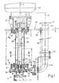
- a centrifugal pump 10 used as a submersible pump has according to Fig. 1 to a equipped with connecting flanges 12, 12 a volute casing 14 - with the interposition of not identified seals - a bearing carrier housing 20.
- a centrifugal pump 10 used as a submersible pump has according to Fig. 1 to a equipped with connecting flanges 12, 12 a volute casing 14 - with the interposition of not identified seals - a bearing carrier housing 20.
- This impeller 28 rotates in the housing space 15 of the screwed to the bearing support housing 20 spiral housing 14 to which a suction chamber 16 connects axially; the inlet of which is designated with 17, the outlet of the housing space 15 with 18.
- the inlet 17 is a Siebansatz 19 prefixed, and near the impeller 28 is located in the bearing support housing 20, a front sliding bearing 30th
- a pump shaft 24 receiving cylindrical Primaaus foundedung 34 - provided with an inner groove 33 for a seal, not shown - which in the interior 35 of a connecting piece or pipe 36 of the diameter d 1 and the length a opens.
- the connection piece 36 is fixed here at one end in a ring 22 bolted to the end face of the bearing carrier housing 20.
- a lower ring 22 which is a second bearing support housing 20 a for a second - pre-set as a ball bearing - shaft bearings.
- a radial rear plate 40 is screwed, which is penetrated by deman a drive 42 connected - shaft end 25.
- the latter is connected by a provided in a clutch housing 44 coupling device 46 with that drive not shown 42.
- the bolted to the clutch housing 44 upper bearing support housing 20 a sits in a direction indicated at 48, radially arranged support plate of thickness f.
- Fig. 2 3rd are the angular profile 60 of the pressure relief hole 38 radial bar profiles 63 opposite.
- the ridge edge 62 of the fixed with its leg edges 61 on the inner surface of the connecting pipe or nozzle 36 angle profile 60 determines a radial plane Q, which also passes through the connecting flange 12 a of the outlet 18 diametrically.
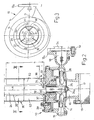
- a centrifugal pump 10 e of 4 to 6 is also the impeller bearing formed as a ball bearing 31, and the connecting piece 36 of the diameter d 1 of about 135 mm and the length a of 495 mm and the angle sections 60 are set at one end in an annular groove 64 of the bearing support housing 20.
- Its inside diameter e measures 72 mm with a groove width b of 32 mm.
- the annular groove 64 is radially adjacent the aforementioned inner groove 33 for a seal, not shown.
- At this annular groove 64 includes the aforementioned ring 20 of an outer diameter e 1 of 195 mm, which is circumferentially surrounded by an edge bead 23 of the bearing support housing 20.
- the other end of the connecting piece 36 superimposed in an annular groove 66 a of a second bearing support housing 20 a for a second ball bearing 31.
- the thickness f of the here also radially the bearing support housing 20 a associated support plate 48 measures 25 mm. Their distance a 1 to the center plane E of the impeller 28 is 600 mm.
- On one side of the connecting piece 36 is in Fig. 4 a longitudinal tube 68 - at a radial distance i 1 of 85 mm of its tube axis B 1 to the shaft axis A - to recognize that opens at both ends into closable transverse channels 69, 69 a of the bearing carrier housing 20, 20 a .
- the transverse channels 69, 69 a are connected to the housing space 15 of the spiral housing 14 for the impeller 28 and with the adjacent to the rear plate 40 storage space 41 for the drive-near ball bearing 31.
- the end edge 72 of the hollow shaft 70 can be seen the end face of the central Anformung (32) of the bearing carrier housing 20, 20 a added.
- the pressure relief holes 38 are preceded by angle profiles 60 and with their leg edges 61 on the wall of the connecting piece 36 welded; whose length n measures 200 mm and their axial distance n 1 from each other about 95 mm.
- connection piece 36 located in this connection piece 36 - as above all Fig. 5, 6 can be seen - coaxial with the pump shaft 24, a hollow shaft 70 of the outer diameter t of 70 mm, which is associated with a closely surrounding interference contour 21 of the bearing housing 20, 20 a .
- Fig. 6 also that rectangular cross-section of the two pairs of angle profiles 60 becomes clear; an angle profile 60 of the mating over completely covers the associated pressure relief bore 38; this provided in the zenith of the connecting piece 36 angle section 60 is on the other side of the shaft axis A in radial distance q of about 80 mm diametrically opposite a lower angle profile 60 of the pairing.
- instead of the angle profiles 60 instead of the angle profiles 60 also - provided in accordance with cross-section - flat iron.
- the attached to the pressure relief holes 38 angle sections 60 cover these, which - as I said - the fluid is deflected and can flow back into the container without foaming. Moreover, the position of the pressure relief hole 38 is offset by 90 ° to the vent hole 68 of the centrifugal pump 10 e . Thanks to this cover of the pressure relief holes 38, the uncontrolled leakage of the fluid into a surrounding container is completely prevented. A rotation of the conveying medium in the connection piece 36 is prevented by the profile of the respective profile ridge edge 62 which is close to that interference contour 21.
- the Fig. 7, 8 show two of the illustration in Fig. 6 corresponding cross sections of other embodiments, to which Fig. 9 a reduced partial longitudinal section of the centrifugal pump 10 n offers.
- the profiled steel formed from two angle sections 60 a are with their Profilefirstkante 62 on the Inner surface of the connecting tube 36 defined on the cross-sectional central axis M, and its interior 59 opens to the interference contour 21 of the bearing support housing 20, to which the leg edges 62 a extend at a distance.
- the diametrical distance between both leg edges 62 a is denoted by q 1 .
- the pressure relief holes 38 are missing both in this sketch and in the example of Fig. 8 ; they are here replaced by radial relief holes 67, which attach in the bearing support housing 20 below the angle sections 60 a and go from the foot of the connecting piece 36 to the outside. 69 is another pressure relief hole marked.
- the Fig. 8 offers instead of that angle profile 60 a also made of section steel existing - channel profile 74 with a by a - fixed to that inner surface of the connecting tube 36 with its longitudinal contours 76 and with this a cavity 77 forming - groove bottom 75 of length g at right angles, ie parallel to Central axis M, projecting trough legs 78 of length h; the leg edges 79 are at a distance from the interference contour 21 of the bearing carrier housing 20 and at a distance q 1 to each other.
- the leg edges 61 are inclined inwardly toward the center axis M.
- the radial relief holes 67 described above are provided.
- a centrifugal pump 10 i after Fig. 10 is the pressure relief hole 38 for protection associated hollow shaft 70 of length z from here 150 mm with the inner surface of the connecting piece 36 by - preferably radially Asked - flat sections or flat bars 80 connected, the lower edges 82 with the bottom or lower end edge 72 of Hollow shaft 70 approximately aligned and so the collar-like Anformung 32 of the bearing support housing 20 sit. Towards the top, the ridge edge 71 projects beyond the hollow shaft 70 the flat bars 80 slightly.
- a sieve set 19 is connected to the connecting flange 12 of the spiral housing 14 by screws 13, moreover.
Landscapes
- Engineering & Computer Science (AREA)
- Mechanical Engineering (AREA)
- General Engineering & Computer Science (AREA)
- Physics & Mathematics (AREA)
- Fluid Mechanics (AREA)
- Structures Of Non-Positive Displacement Pumps (AREA)
- Lubrication Of Internal Combustion Engines (AREA)
- Reciprocating Pumps (AREA)
Description
- Die Erfindung betrifft eine Kreiselpumpe zum Fördern eines Fördermediums mit in einem Spiralgehäuse vorgesehenem Laufrad sowie dem Spiralgehäuse zugeordnetem Lagerträgergehäuse für zumindest ein Lager einer an das Laufrad angeschlossenen Pumpenwelle, die andernends ein weiteres Lagerträgergehäuse durchsetzt und jenseits dessen an einen Antrieb angeschlossen ist; zwischen den beiden Lagerträgergehäusen erstreckt sich ein die Pumpenwelle umgebender Verbindungsstutzen bzw. ein Verbindungsrohr.
- Eine derartige Pumpe ist der
US 3,731,940 A zu entnehmen mit horizontaler Pumpenwelle, die zwei Kugellager durchsetzt, von denen jedes in einem Lagergehäuse sitzt. Beide Lagergehäuse befinden sich radial in einem seinerseits an einen Ständer der Pumpe angeschraubten Rohrstutzen. - Weitere gattungsgemäßen Pumpen sind aus
US 6,315,530 B undUS 4,394,140 A bekannt. Bekannt sind auch Tauch- oder Förderpumpen mit vertikal angeordneter Pumpenwelle in einem Hüllrohr. In diesem wird durch die Rotation der Pumpenwelle das Fördermedium in Drehbewegung gebracht und im Falle vorhandener Öffnungen im Hüllrohr durch diese geschleudert. Ein ungewolltes Aufschäumen des Fördermediums und Lufteinschlüsse durch die Pumpbewegung in diesem sind die Folge. - In Kenntnis dieses Standes der Technik hat sich der Erfinder das Ziel gesetzt, die Laufeigenschaften solcher Pumpen zu verbessern und die geschilderten Mängel zu beseitigen.
- Zur Lösung dieser Aufgabe führt die Lehre nach dem unabhängigen Schutzanspruch; die Unteransprüche geben günstige Weiterbildungen an. Zudem fallen in den Rahmen der Erfindung alle Kombinationen aus zumindest zwei der in der Beschreibung, der Zeichnung und/oder den Ansprüchen offenbarten Merkmale.
- Erfindungsgemäß ist in der Wandung des Verbindungsstutzens oder -rohres wenigstens eine Druckentlastungsbohrung vorgesehen und dieser innenseitig ein sie überdeckendes Teilhohlprofil zugeordnet, welches parallel zur Wellenachse und in radialem Abstand zur Pumpenwelle verläuft; die Druckentlastungsbohrungen können erfindungsgemäß auch -- statt in der Wandung des Verbindungsstutzens -- an letzteren durch das benachbarte Lagerträgergehäuse -- bevorzugt radialherangeführt sein.
- Als günstig hat es sich erwiesen, dass von jedem der beiden Lagerträgergehäuse ein -- parallel zu seiner Längsachse geteiltes, also rinnenartiges -- Hohlprofil ausgeht; welches zumindest eine dem Lagerträgergehäuse benachbarte Druckentlastungsbohrung übergreift. Dazu hat es sich als günstig erwiesen, dass beide Teilhohlprofile miteinander fluchten und in Abstand zueinander enden.
- Im Rahmen der Erfindung liegt ein Winkelprofil als Teilhohlprofil, das mit seinen Schenkelkanten beidseits der Druckentlastungsbohrung/en am Verbindungsstutzen innenseitig festgelegt ist und dessen Profilfirstkante in Abstand zur Pumpenwelle verläuft. Dank dieser Abdeckung der Druckentlastungsbohrungen mit dem Winkelprofil wird das unkontrolierte Austreten des Fördermediums in einen umgebenden Behälter verhindert, und ein Rotieren des Fördermediums im Verbindungsstück wird durch das Vorstehen der Winkelkanten unterbunden.
- Bei Ausgestaltungen mit das Lagergehäuse durchsetzenden radialen Druckentlastungsbohrungen wird das Winkelprofil bevorzugt mit seiner Profilfirstkante innenseitig am Verbindungsstutzen festgelegt, öffnet sich also achswärts; seine Schenkelendkanten verlaufen in Abstand zur Pumpenwelle.
- Auch können erfindungsgemäß rinnenartige Teilhohlprofilebevorzugt rechteckigen Querschnitts -- eingesetzt werden; der Rinnenboden dieses Rinnenprofils ist vorteilhafterweise beidseits innenseitig am Verbindungsstutzen festgelegt und seine Rinnenschenkel ragen zum Verbindungsstutzen hin ab. Im übrigen sollen auch hier die -- querschnittlich bevorzugt achswärts zum Rinnenboden hin nach innen geneigtenSchenkelkanten der Rinnenschenkel in Abstand zur Pumpenwelle stehen.
- Diesen sich achswärts öffnenden Winkelprofilen bzw. den Rinnenprofilen sind die oben erwähnten radialen Entlastungsbohrungen bevorzugt zugeordnet.
- Die Winkelprofile sind erfindungsgemäß an unteren und oberen Entlastungsbohrungen der Tauchpumpe angebracht und verdecken diese. Dadurch wird das Fördermedium umgelenkt und kann ohne Schaumbildung in jenen Behälter zurückfließen.
- Nach einem weiteren Merkmal der Erfindung liegt dem die Druckentlastungsbohrung/en überdeckenden Teilhohl- oder Winkelprofil diametral ein weiteres Profil -- bevorzugt ebenfalls ein Winkelprofil -- gegenüber. Allerdings ist es auch denkbar, dass von dem dem Teilhohl- oder Winkelprofil gegenüberstehenden Wandungsbereich des Verbindungsstutzens zumindest zwei weitere Profile in seitlichem Abstand zueinander abragen, bevorzugt radiale Stegprofile.
- Zur Festlegung des Verbindungsstutzens hat es sich als günstig erwiesen, diesen endwärts -- mit dem einen Ende der/des innenseitig in ihm festgelegten Profile/s -- in einer Ringnut des Lagerträgergehäuses anzuordnen.
- Die Druckentlastungsbohrung/en und deren Teilhohl- oder Winkelprofil/e sollen zudem vorteilhafterweise in einer Radialebene liegen, in welcher sich der Auslass des Spiralgehäuses befindet.
- Nach einem weiteren Merkmal der Erfindung ist die Pumpenwelle von einer Hohlwelle umfangen und diese in radialem Abstand zu dem/den Profile/n angeordnet; diese Hohlwelle soll mit ihrer Endkante einer zentralen Anformung des Lagerträgergehäuses anliegen, welche von der Pumpenwelle durchsetzt ist; der Außenfläche der Hohlwelle ist im übrigen an den Stirnflächen der Lagerträgergehäuse eine Störkontur benachbart.
- Die erfindungsgemäße Zuordnung der Pumpenteile ist so gewählt, dass der radiale Abstand der Pumpenwelle von der Hohlwelle etwa deren radialem Abstand von der/den Profilfirstkante/n entspricht. Zudem soll an der Außenseite des Verbindungsstutzens ein Längsrohr -- bevorzugt parallel zur Wellenachse gerichtet -- verlaufen, das Querkanäle in beiden Lagerträgergehäusen miteinander verbindet und so für eine einheitliche Entlüftung sorgt.
- Das erfindungsgemäße Teilhohlprofil besteht aus mehreren Komponenten, welche die Druckentlastungsbohrung/en abdecken. Zudem sollen von der Innenfläche des Verbindungsstutzens achswärts Flachprofile abragen; die -- den Fuß der Pumpenwelle umfangende -- Hohlwelle wird durch Flachprofile mit der Innenfläche des Verbindungsstutzens verbunden.
- Weitere Vorteile, Merkmale und Einzelheiten der Erfindung ergeben sich aus der nachfolgenden Beschreibung bevorzugter Ausführungsbeispiele sowie anhand der Zeichnung; diese zeigt in
- Fig. 1, 4:
- jeweils einen Längsschnitt durch eine Ausgestaltung einer Kreiselpumpe;
- Fig. 2, 5:
- jeweils ein vergrößertes Detail aus
Fig. 1 bzw.Fig. 4 ; - Fig. 3:
- den vergrößerten Querschnitt durch
Fig. 1 ,2 nach deren Linie III-III; - Fig. 6:
- den vergrößerten Querschnitt durch
Fig. 5 nach deren Linie VI-VI; - Fig. 7, 8:
- zwei weitere Ausführungsbeispiele in einer der
Fig. 6 entsprechenden Querschnittsdarstellung; - Fig. 9:
- einen gegenüber
Fig. 1 ,4 verkleinerten Teillängsschnitt durch eine Kreiselpumpe zur Ausgestaltung nachFig. 7, 8 ; - Fig. 10:
- einen vergrößerten Teillängsschnitt durch eine weitere Ausgestaltung der Kreiselpumpe.
- Eine als Tauchpumpe eingesetzte Kreiselpumpe 10 weist gemäß
Fig. 1 an einem mit Anschlussflanschen 12, 12a ausgestatteten Spiralgehäuse 14 -- unter Zwischenschaltung von nicht kenntlich gemachten Dichtungen -- ein Lagerträgergehäuse 20 auf. In diesem sitzt auf dem vorderen gestuften Ende 24a einer Pumpenwelle 24 eines Durchmessers d ein Laufrad 28 und wird von einer Mutter 26 gehalten. Dieses Laufrad 28 dreht sich im Gehäuseraum 15 des mit dem Lagerträgergehäuse 20 verschraubten Spiralgehäuses 14, an den axial ein Saugraum 16 anschließt; dessen Einlass ist mit 17 bezeichnet, der Auslass des Gehäuseraumes 15 mit 18. Dem Einlass 17 ist ein Siebansatz 19 vorgesetzt, und nahe dem Laufrad 28 befindet sich im Lagerträgergehäuse 20 ein vorderes Gleitlager 30. - In einer ringartigen Anformung 32 des Lagerträgergehäuses 20 ist eine die Pumpenwelle 24 aufnehmende zylindrische Zentralausnehmung 34 -- mit einer Innennut 33 für eine nicht dargestellte Dichtung -- vorgesehen, welche in den Innenraum 35 eines Verbindungsstutzens oder -rohres 36 des Durchmessers d1 sowie der Länge a mündet. Der Verbindungsstutzen 36 ist hier einends in einem an der Stirnfläche des Lagerträgergehäuses 20 angeschraubten Ring 22 festgelegt.
- Das andere Ende des Verbindungsstutzens 36, der in Mittenabstand c zu seinen Endkanten 37 mit Druckentlastungsbohrungen 38 ausgestattet ist, ruht in einem unteren Ring 22, der einem zweiten Lagerträgergehäuse 20a für ein zweites - als Kugellager 31 ausgebildetes -- Wellenlager vorgesetzt ist. An dieses -- in
Fig. 1 obere -- Lagerträgergehäuse 20a ist eine radiale Heckplatte 40 angeschraubt, die von deman einen Antrieb 42 angeschlossenen -- Wellenende 25 durchsetzt ist. Letzteres wird durch eine in einem Kupplungsgehäuse 44 vorgesehene Kupplungseinrichtung 46 mit jenem nicht weiter dargestellten Antrieb 42 verbunden. Das mit dem Kupplungsgehäuse 44 verschraubte obere Lagerträgergehäuse 20a sitzt in einer bei 48 angedeuteten, radial angeordneten Trägerplatte der Dicke f. - Parallel zur Wellenachse A sowie in radialem Abstand i zu ihr verläuft die Längsachse B eines Austragsrohres 50, das jene Trägerplatte 48 durchsetzt, über der es mit einem Flansch 51 endet. Andernends ist das Austragsrohr 50 unter Zwischenschaltung eines Schließorgans 52 an einen Krümmer 54 angeschlossen, der an den Anschlussflansch 12a des Spiralgehäuses 14 angefügt ist. Parallel zu jener Längsachse B ist eine Steuerleitung 56 eines Steuerorgans 58 zu erkennen, das in der Trägerplatte 48 lagert.
- Durch die Rotation der Pumpenwelle 24 wird Fördermedium der Tauchpumpe 10 in dem Verbindungsstutzen 36 in Rotation versetzt sowie durch die beschriebenen Druckentlastungsbohrungen 38 geschleudert. Da für diesen Pumpeneinsatz ein ungewolltes Aufschäumen des Fördermediums sowie Lufteinschlüsse durch die Pumpenbewegung nachteilig sind, wird ein unkontrolliertes Austreten von Fördermedium durch eine Abdeckung der Druckentlastungsbohrungen 38 hintangehalten. Dazu befindet sich innerhalb des Verbindungsstutzens 36wie vor allem
Fig. 3 erkennen läßt -- ein der Druckentlastungsbohrung 38 vorgesetztes Teilhohlprofil in Form eines Winkelprofils 60 der Länge n, dessen i.w. rechtwinkeliger Querschnitt symmetrisch zur Mittelachse M der Druckentlastungsbohrung 38 verläuft sowie in radialem Abstand zur Projektion der Anformung 32. - In
Fig. 2, 3 liegen dem Winkelprofil 60 der Druckentlastungsbohrung 38 radiale Stegprofile 63 gegenüber. Die Firstkante 62 des mit seinen Schenkelkanten 61 an der Innenfläche des Verbindungsrohres oder -stutzens 36 festliegenden Winkelprofils 60 bestimmt eine Radialebene Q, welche auch den Anschlussflansch 12a des Auslasses 18 diametral durchsetzt. - Beim Ausführungsbeispiel einer Kreiselpumpe 10e der
Fig. 4 bis 6 ist auch das laufradnahe Lager als Kugellager 31 ausgebildet, und der Verbindungsstutzen 36 des Durchmessers d1 von etwa 135 mm sowie der Länge a von 495 mm sowie die Winkelprofile 60 sind einends in einer Ringnut 64 des Lagerträgergehäuses 20 festgelegt. Deren Innendurchmesser e misst 72 mm bei einer Nutbreite b von 32 mm. Der Ringnut 64 ist die erwähnte Innennut 33 für eine nicht gezeigte Dichtung radial benachbart. An diese Ringnut 64 schließt der erwähnte Ring 20 eines Außendurchmessers e1 von 195 mm an, der nach außen hin von einem Randwulst 23 des Lagerträgergehäuses 20 umfangen ist. - Auch das andere Ende des Verbindungsstutzens 36 lagert in einer Ringnut 66a eines zweiten Lagerträgergehäuses 20a für ein zweites Kugellager 31. Die Dicke f der hier ebenfalls radial dem Lagerträgergehäuse 20a zugeordneten Trägerplatte 48 misst 25 mm. Deren Abstand a1 zur Mittelebene E des Laufrades 28 beträgt 600 mm. An einer Seite des Verbindungsstutzens 36 ist in
Fig. 4 ein Längsrohr 68 -- in Radialabstand i1 von 85 mm seiner Rohrachse B1 zur Wellenachse A -- zu erkennen, das beidends in verschließbare Querkanäle 69, 69a der Lagerträgergehäuse 20, 20a mündet. Die Querkanäle 69, 69a sind mit dem Gehäuseraum 15 des Spiralgehäuses 14 für das Laufrad 28 bzw. mit dem an die Heckplatte 40 grenzenden Lagerraum 41 für das antriebsnahe Kugellager 31 verbunden. - Die Endkante 72 der Hohlwelle 70 ist erkennbar der Stirnfläche der zentrischen Anformung (32) des Lagerträgergehäuses 20, 20a angefügt.
- Beidends des Verbindungsstutzens 36 sind in diesem den Druckentlastungsbohrungen 38 Winkelprofile 60 vorgesetzt und mit ihren Schenkelkanten 61 an der Wandung des Verbindungsstutzens 36 verschweißt; deren Länge n misst 200 mm und deren axialer Abstand n1 voneinander etwa 95 mm.
- Zudem befindet sich in diesem Verbindungsstutzen 36 -- wie vor allem
Fig. 5, 6 zu entnehmen -- koaxial zur Pumpenwelle 24 eine Hohlwelle 70 des äußeren Durchmessers t von 70 mm, der eine sie eng umgebende Störkontur 21 des Lagergehäuses 20, 20a zugeordnet ist. InFig. 6 wird auch jener rechtwinkelige Querschnitt der beiden Paare von Winkelprofilen 60 deutlich; ein Winkelprofil 60 der Paarung über deckt die zugeordnete Druckentlastungsbohrung 38 völlig; diesem im Zenit des Verbindungsstutzens 36 vorgesehenen Winkelprofil 60 liegt auf der anderen Seite der Wellenachse A in Radialabstand q von etwa 80 mm jeweils diametral ein unteres Winkelprofil 60 der Paarung gegenüber. Bei anderen Ausführungen können statt den Winkelprofilen 60 auch -- querschnittlich entsprechend gestellte -- Flacheisen vorgesehen sein. - Die an den Druckentlastungsbohrungen 38 angebrachten Winkelprofile 60 decken diese ab, wodurch -- wie gesagt -- das Fördermedium umgelenkt wird und ohne Schaumbildung in den Behälter zurückfließen kann. Im übrigen ist die Lage der Druckentlastungsbohrung 38 um 90° versetzt zur Entlüftungsbohrung 68 der Kreiselpumpe 10e. Dank dieser Abdeckung der Druckentlastungsbohrungen 38 wird das unkontrollierte Austreten des Fördermediums in einen umgebenden Behälter gänzlich verhindert. Ein Rotieren des Fördermediums im Verbindungsstutzen 36 wird durch den jener Störkontur 21 nahen Verlauf der jeweiligen Profilfirstkante 62 unterbunden.
- Die
Fig. 7, 8 zeigen zwei der Darstellung inFig. 6 entsprechende Querschnitte anderer Ausgestaltungen, zu denenFig. 9 einen verkleinerten Teillängsschnitt der Kreiselpumpe 10n anbietet. Die aus Profilstahl geformten beiden Winkelprofile 60a sind mit ihrer Profilfirstkante 62 an der Innenfläche des Verbindungsrohres 36 auf der Querschnittsmittelachse M festgelegt, und ihr Innenraum 59 öffnet sich zur Störkontur 21 des Lagerträgergehäuses 20 hin, zu welcher die Schenkelkanten 62a in Abstand verlaufen. Der diametrale Abstand beider Schenkelkanten 62a ist mit q1 bezeichnet. Die Druckentlastungsbohrungen 38 fehlen sowohl in dieser Skizze als auch beim Beispiel derFig. 8 ; sie sind hier ersetzt durch radiale Entlastungsbohrungen 67, die im Lagerträgergehäuse 20 unterhalb der Winkelprofile 60a ansetzen und vom Fuße des Verbindungsstutzens 36 nach außen gehen. Mit 69 ist eine andere Druckentlastungsbohrung gekennzeichnet. - Die
Fig. 8 bietet statt jenes Winkelprofils 60a einebenfalls aus Profilstahl bestehendes -- Rinnenprofil 74 an mit von einem -- an jener Innenfläche des Verbindungsrohres 36 mit seinen Längskonturen 76 festliegenden und mit dieser einen Hohlraum 77 bildenden -- Rinnenboden 75 der Länge g rechtwinkelig, d.h. parallel zur Mittelachse M, abragenden Rinnenschenkeln 78 der Länge h; die Schenkelkanten 79 stehen in Abstand zur Störkontur 21 des Lagerträgergehäuses 20 sowie in Abstand q1 zueinander. Zudem sind die Schenkelkanten 61 zur Mittelachse M hin einwärts geneigt. Auch hierzu sind die oben beschriebenen radialen Entlastungsbohrungen 67 vorgesehen. - Beim Ausführungsbeispiel einer Kreiselpumpe 10i nach
Fig. 10 ist die der Druckentlastungsbohrung 38 zum Schutz zugeordnete Hohlwelle 70 der Länge z von hier 150 mm mit der Innenfläche des Verbindungsstutzens 36 durch -- bevorzugt radial gestellte -- Flachprofile bzw. Flacheisen 80 verbunden, deren Unterkanten 82 mit der Fuß- oder unteren Endkante 72 der Hohlwelle 70 etwa fluchten und so der kragenartigen Anformung 32 des Lagerträgergehäuses 20 aufsitzen. Nach oben hin überragt die Firstkante 71 der Hohlwelle 70 die Flacheisen 80 geringfügig. Auch hier ist im übrigen ein Siebansatz 19 mit dem Anschlussflansch 12 des Spiralgehäuses 14 durch Schrauben 13 verbunden.
Claims (18)
- Kreiselpumpe zum Fördern eines Fördermediums mit in einem Spiralgehäuse (14) vorgesehenem Laufrad (28) sowie dem Spiralgehäuse (14) zugeordnetem Lagerträgergehäuse (20) für zumindest ein Lager (30, 31) einer an das Laufrad (28) angeschlossenen Pumpenwelle (24), die andernends ein weiteres Lagerträgergehäuse (20a) durchsetzt und jenseits dessen an einen Antrieb (42) angeschlossen ist, wobei sich zwischen den Lagerträgergehäusen (20, 20a) ein die Pumpenwelle (24) umgebendes Verbindungsrohr (36) erstreckt,
dadurch gekennzeichnet,
dass in der Wandung des Verbindungsrohres oder Verbindungsstutzens (36) wenigstens eine Druckentlastungsbohrung (38) vorgesehen und dieser innenseitig ein sie überdeckendes Teilhohlprofil (60, 60a, 74) zugeordnet ist, welches parallel zur Wellenachse (A) und in radialem Abstand zur Pumpenwelle (24) verläuft oder, dass wenigstens eine Druckentlastungsbohrung (67) unterhalb der/des Teilhohlprofile/s (60a, 74) durch das diesem/diesen benachbarte Lagerträgergehäuse (20, 20a) geführt ist. - Kreiselpumpe nach Anspruch 1, dadurch gekennzeichnet, dass das Teilhohlprofil (60, 60a, 74) ein parallel zu seiner Längsachse (A) geteiltes Hohlprofil sowie rinnenartig ausgebildet ist.
- Kreiselpumpe nach Anspruch 1 oder 2, dadurch gekennzeichnet, dass von jedem der Lagerträgergehäuse (20, 20a) ein Teilhohlprofil (60, 60a, 74) ausgeht, welches zumindest eine dem Lagerträgergehäuse benachbarte Druckentlastungsbohrung (38) übergreift, wobei gegebenenfalls beide Teilhohlprofile (60, 60a, 74) miteinander fluchten und in Abstand (n1) zueinander enden.
- Kreiselpumpe nach einem der Ansprüche 1 bis 3, dadurch gekennzeichnet, dass das Teilhohlprofil ein Winkelprofil (60) ist, das mit seinen Schenkelkanten (61) beidseits der Druckentlastungsbohrung/en (38) am Verbindungsstutzen (36) innenseitig festgelegt ist und dessen Profilfirstkante (62) in Abstand zur Pumpenwelle (24) verläuft.
- Kreiselpumpe nach einem der Ansprüche 1 bis 3, dadurch gekennzeichnet, dass das Teilhohlprofil ein Winkelprofil (60a) ist, das mit seiner Profilfirstkante (62) am Verbindungsstutzen (36) innenseitig festgelegt ist und dessen Schenkelkanten (61) in Abstand zur Pumpenwelle (24) verlaufen.
- Kreiselpumpe nach einem der Ansprüche 1 bis 3, dadurch gekennzeichnet, dass das Teilhohlprofil ein Rinnenprofil (74) ist, dessen Rinnenboden (75) beidseits am Verbindungsstutzen (36) innenseitig festgelegt ist und dessen Rinnenschenkel (78) zum Verbindungsstutzen (36) hin abragen, wobei gegebenenfalls das Rinnenprofil (74) einen rechteckigen Querschnitt aufweist.
- Kreiselpumpe nach Anspruch 6, dadurch gekennzeichnet, dass die Schenkelkanten (79) der Rinnenschenkel (78) querschnittlich zum Rinnenboden (75) hin geneigt sind und/oder, dass die Schenkelkanten (79) der Rinnenschenkel (78) in Abstand zur Pumpenwelle (24) verlaufen.
- Kreiselpumpe nach einem der Ansprüche 1, 5 bis 7, dadurch gekennzeichnet, dass die Druckentlastungsbohrung/en (67) den sich achswärts öffnenden Winkelprofilen (60a) bzw. den Rinnenprofilen (74) zugeordnet sind.
- Kreiselpumpe nach einem der Ansprüche 1 bis 8, dadurch gekennzeichnet, dass dem die Druckentlastungsbohrung/en (38) überdeckenden Teilhohl- oder Winkelprofil (60, 60a, 74) diametral ein weiteres Profil (60, 60a, 74; 63), bevorzugt ein gleich gestaltetes Profil, gegenüber liegt.
- Kreiselpumpe nach einem der Ansprüche 1 bis 4, dadurch gekennzeichnet, dass von dem dem Teilhohl- oder Winkelprofil (60) gegenüberliegenden Wandungsbereich des Verbindungsstutzens (36) zumindest zwei weitere Profile, bevorzugt radiale Stegprofile (63), in seitlichem Abstand zueinander abragen.
- Kreiselpumpe nach einem der Ansprüche 1 bis 10, dadurch gekennzeichnet, dass der Verbindungsstutzen (36) endwärts mit dem einen Ende der/des innenseitig in ihm festgelegten Profile/s (60, 63) in einer Ringnut (64) des Lagerträgergehäuses (20, 20a) angeordnet ist.
- Kreiselpumpe nach einem der Ansprüche 1 bis 11, dadurch gekennzeichnet, dass die Druckentlastungsbohrung/en (38) und deren Teilhohl- oder Winkelprofil/e (60) in einer Radialebene (Q) liegen, in welcher sich der Auslass (18) des Spiralgehäuses (14) befindet.
- Kreiselpumpe nach einem der Ansprüche 1 bis 12, dadurch gekennzeichnet, dass die Pumpenwelle (24) von einer Hohlwelle (70) umfangen und diese in radialem Abstand zu dem/den Profil/en (60, 60a, 74; 63) angeordnet ist, wobei gegebenenfalls die Hohlwelle (70) mit ihrer Endkante (72) einer zentralen Anformung (32) des Lagerträgergehäuses (20, 20a) anliegt, welche von der Pumpenwelle (24) durchsetzt ist.
- Kreiselpumpe nach Anspruch 13, dadurch gekennzeichnet, dass der Außenfläche der Hohlwelle (70) an der Stirnfläche des Lagerträgergehäuses (20, 20a) eine Störkontur (21) benachbart ist.
- Kreiselpumpe nach Anspruch 13 oder 14, dadurch gekennzeichnet, dass der radiale Abstand der Pumpenwelle (24) von der Hohlwelle (70) etwa deren radialem Abstand von der/den Profilfirstkante/n (62) entspricht.
- Kreiselpumpe nach einem der Ansprüche 1 bis 15, dadurch gekennzeichnet, dass an der Außenseite des Verbindungsstutzens (36) ein Längsrohr (66) verläuft, das Querkanäle (68) in beiden Lagerträgergehäusen (20, 20a) miteinander verbindet, wobei gegebenenfalls das Längsrohr (66) parallel zur Wellenachse (A) gerichtet ist.
- Kreiselpumpe nach einem der Ansprüche 10 bis 16, dadurch gekennzeichnet, dass die Hohlwelle (70) den Fuß der Pumpenwelle (24) umfängt.
- Kreiselpumpe nach einem der Ansprüche 1 bis 16, dadurch gekennzeichnet, dass das Teilhohlprofil aus mehreren Komponenten besteht, welche die Druckentlastungsbohrung/en (36) abdecken, wobei gegebenenfalls von der Innenfläche des Verbindungsstutzens (36) achswärts Flachprofile (80) abragen und/oder die Hohlwelle (70) durch Flachprofile (80) mit der Innenfläche des Verbindungsstutzens (36) verbunden ist.
Applications Claiming Priority (3)
| Application Number | Priority Date | Filing Date | Title |
|---|---|---|---|
| DE10237352 | 2002-08-12 | ||
| DE10237352 | 2002-08-12 | ||
| PCT/EP2003/008697 WO2004022979A1 (de) | 2002-08-12 | 2003-08-06 | Kreiselpumpe |
Publications (2)
| Publication Number | Publication Date |
|---|---|
| EP1529167A1 EP1529167A1 (de) | 2005-05-11 |
| EP1529167B1 true EP1529167B1 (de) | 2010-03-17 |
Family
ID=30775290
Family Applications (1)
| Application Number | Title | Priority Date | Filing Date |
|---|---|---|---|
| EP03793695A Expired - Lifetime EP1529167B1 (de) | 2002-08-12 | 2003-08-06 | Kreiselpumpe |
Country Status (5)
| Country | Link |
|---|---|
| EP (1) | EP1529167B1 (de) |
| AT (1) | ATE461367T1 (de) |
| DE (3) | DE10256792B4 (de) |
| ES (1) | ES2342597T3 (de) |
| WO (1) | WO2004022979A1 (de) |
Families Citing this family (8)
| Publication number | Priority date | Publication date | Assignee | Title |
|---|---|---|---|---|
| US7492069B2 (en) * | 2001-04-19 | 2009-02-17 | Baker Hughes Incorporated | Pressurized bearing system for submersible motor |
| DE102005013684A1 (de) * | 2005-03-17 | 2006-09-21 | Flux-Geräte GmbH | Behälterpumpe, vorzugsweise zum Fördern von Harnstoff |
| CN107152407A (zh) * | 2017-06-21 | 2017-09-12 | 江苏建安泵业制造有限公司 | 一种输送颗粒及粘度介质的涂装用液下泵 |
| CA3221415A1 (en) | 2021-05-24 | 2022-12-01 | Flsmidth A/S | Tank pump having a tangential feed inlet and variable geometry infeed shelf |
| CN113357159B (zh) * | 2021-07-05 | 2022-05-31 | 陈荣国 | 基于直流永磁电机的自吸式复合屏蔽泵 |
| CN115788919A (zh) | 2021-09-09 | 2023-03-14 | 创科无线普通合伙 | 潜水泵 |
| US20250172159A1 (en) * | 2022-04-15 | 2025-05-29 | Weir Pump and Valve Solutions, Inc. | Centrifugal Pump Casing With Strainer Device Attachment |
| WO2023218426A1 (en) | 2022-05-12 | 2023-11-16 | Flsmidth A/S | Froth transport system, de-aeration device, and method for efficiently pumping frothy or aerated slurries |
Family Cites Families (8)
| Publication number | Priority date | Publication date | Assignee | Title |
|---|---|---|---|---|
| DE747143C (de) * | 1941-04-04 | 1944-09-11 | Galassi Ortolani & Mueller | Kreiselpumpe |
| US3731940A (en) * | 1971-08-06 | 1973-05-08 | W Spruiell | Elastomer seal with a plurality of annular ribs for a rotating shaft of a centrifugal pump or the like |
| DE2262017C3 (de) * | 1972-12-19 | 1981-07-02 | H. Wernert & Co Kg, 4330 Muelheim | Vertikale, hängende Kreiselpumpe |
| US3936221A (en) * | 1974-09-16 | 1976-02-03 | Goulds Pumps, Inc. | Vertical cantilever pump |
| US4394140A (en) * | 1977-12-30 | 1983-07-19 | Smith International, Inc. | Degassing system and centrifugal pump |
| FR2717535A1 (fr) * | 1994-03-17 | 1995-09-22 | Siebec Sa | Pompe verticale. |
| US6315530B1 (en) * | 1999-10-05 | 2001-11-13 | Buffalo Pumps, Inc. | Submerged pump having a shaft isolator |
| DE10051324C1 (de) * | 2000-10-17 | 2002-02-21 | Brinkmann Pumpen K H Brinkmann | Flüssigkeitspumpe mit Spritzschutz |
-
2002
- 2002-12-05 DE DE10256792A patent/DE10256792B4/de not_active Expired - Lifetime
-
2003
- 2003-08-06 AT AT03793695T patent/ATE461367T1/de not_active IP Right Cessation
- 2003-08-06 DE DE50312528T patent/DE50312528D1/de not_active Expired - Lifetime
- 2003-08-06 ES ES03793695T patent/ES2342597T3/es not_active Expired - Lifetime
- 2003-08-06 EP EP03793695A patent/EP1529167B1/de not_active Expired - Lifetime
- 2003-08-06 WO PCT/EP2003/008697 patent/WO2004022979A1/de not_active Ceased
- 2003-08-07 DE DE10336947A patent/DE10336947A1/de not_active Withdrawn
Also Published As
| Publication number | Publication date |
|---|---|
| DE50312528D1 (de) | 2010-04-29 |
| ES2342597T3 (es) | 2010-07-09 |
| WO2004022979A1 (de) | 2004-03-18 |
| DE10256792A1 (de) | 2004-03-04 |
| EP1529167A1 (de) | 2005-05-11 |
| ATE461367T1 (de) | 2010-04-15 |
| DE10256792B4 (de) | 2005-01-13 |
| DE10336947A1 (de) | 2004-02-26 |
Similar Documents
| Publication | Publication Date | Title |
|---|---|---|
| DE2130474C3 (de) | Zentrifugalpumpe | |
| DE69629606T2 (de) | Pumpe mit einem verbesserten Durchflusskanal | |
| DE69329657T2 (de) | Pumpengehäuse in Blechbauweise | |
| CH628116A5 (en) | Submersible pump, especially drum pump | |
| EP1529167B1 (de) | Kreiselpumpe | |
| DE102007032228A1 (de) | Selbstansaugende Pumpenaggregation | |
| DE7507522U (de) | Kreiselpumpe | |
| DE3517828A1 (de) | Pumpengehaeuse | |
| DE1403540A1 (de) | Pumpe | |
| EP3085961A1 (de) | Mehrstufige kreiselpumpe | |
| DE2262017C3 (de) | Vertikale, hängende Kreiselpumpe | |
| EP1148248A2 (de) | Pumpengehäuse | |
| DE102007012661B4 (de) | Tauchpumpenaggregat | |
| EP3978760B1 (de) | Tauchkreiselpumpe | |
| DE2522165A1 (de) | Kreiselpumpe | |
| DE9208801U1 (de) | Pumpenaggregat | |
| DE4239071A1 (de) | Tauchpumpenaggregat | |
| DE29823424U1 (de) | Kreiselpumpe mit Gleitringdichtung | |
| DE19834012C2 (de) | Kreiselpumpe mit Gleitringdichtung | |
| DE10112018A1 (de) | Tauchpumpe, insbesondere für Abwasser, Gülle oder dickflüssige Massen | |
| EP1411249B1 (de) | Kreiselpumpeneinheit | |
| DE4214026A1 (de) | Pumpengehaeuse | |
| EP0995906A1 (de) | Motorgetriebene Doppelpumpe der Kreiselpumpenbauart | |
| DE102006006253A1 (de) | Pumpwerk | |
| DE4231785A1 (de) | Radialkolbenpumpe mit integriertem Resonator |
Legal Events
| Date | Code | Title | Description |
|---|---|---|---|
| PUAI | Public reference made under article 153(3) epc to a published international application that has entered the european phase |
Free format text: ORIGINAL CODE: 0009012 |
|
| 17P | Request for examination filed |
Effective date: 20040423 |
|
| AK | Designated contracting states |
Kind code of ref document: A1 Designated state(s): AT BE BG CH CY CZ DE DK EE ES FI FR GB GR HU IE IT LI LU MC NL PT RO SE SI SK TR |
|
| RIN1 | Information on inventor provided before grant (corrected) |
Inventor name: WEIDELE, EDGAR |
|
| GRAP | Despatch of communication of intention to grant a patent |
Free format text: ORIGINAL CODE: EPIDOSNIGR1 |
|
| GRAS | Grant fee paid |
Free format text: ORIGINAL CODE: EPIDOSNIGR3 |
|
| GRAA | (expected) grant |
Free format text: ORIGINAL CODE: 0009210 |
|
| AK | Designated contracting states |
Kind code of ref document: B1 Designated state(s): AT BE BG CH CY CZ DE DK EE ES FI FR GB GR HU IE IT LI LU MC NL PT RO SE SI SK TR |
|
| REG | Reference to a national code |
Ref country code: GB Ref legal event code: FG4D Free format text: NOT ENGLISH |
|
| REG | Reference to a national code |
Ref country code: CH Ref legal event code: EP |
|
| REG | Reference to a national code |
Ref country code: IE Ref legal event code: FG4D |
|
| REF | Corresponds to: |
Ref document number: 50312528 Country of ref document: DE Date of ref document: 20100429 Kind code of ref document: P |
|
| REG | Reference to a national code |
Ref country code: CH Ref legal event code: NV Representative=s name: BODENSEEPATENT GMBH |
|
| REG | Reference to a national code |
Ref country code: SE Ref legal event code: TRGR |
|
| REG | Reference to a national code |
Ref country code: ES Ref legal event code: FG2A Ref document number: 2342597 Country of ref document: ES Kind code of ref document: T3 |
|
| REG | Reference to a national code |
Ref country code: NL Ref legal event code: VDEP Effective date: 20100317 |
|
| PG25 | Lapsed in a contracting state [announced via postgrant information from national office to epo] |
Ref country code: SI Free format text: LAPSE BECAUSE OF FAILURE TO SUBMIT A TRANSLATION OF THE DESCRIPTION OR TO PAY THE FEE WITHIN THE PRESCRIBED TIME-LIMIT Effective date: 20100317 |
|
| REG | Reference to a national code |
Ref country code: IE Ref legal event code: FD4D |
|
| PG25 | Lapsed in a contracting state [announced via postgrant information from national office to epo] |
Ref country code: CY Free format text: LAPSE BECAUSE OF FAILURE TO SUBMIT A TRANSLATION OF THE DESCRIPTION OR TO PAY THE FEE WITHIN THE PRESCRIBED TIME-LIMIT Effective date: 20100317 Ref country code: EE Free format text: LAPSE BECAUSE OF FAILURE TO SUBMIT A TRANSLATION OF THE DESCRIPTION OR TO PAY THE FEE WITHIN THE PRESCRIBED TIME-LIMIT Effective date: 20100317 Ref country code: RO Free format text: LAPSE BECAUSE OF FAILURE TO SUBMIT A TRANSLATION OF THE DESCRIPTION OR TO PAY THE FEE WITHIN THE PRESCRIBED TIME-LIMIT Effective date: 20100317 Ref country code: NL Free format text: LAPSE BECAUSE OF FAILURE TO SUBMIT A TRANSLATION OF THE DESCRIPTION OR TO PAY THE FEE WITHIN THE PRESCRIBED TIME-LIMIT Effective date: 20100317 Ref country code: GR Free format text: LAPSE BECAUSE OF FAILURE TO SUBMIT A TRANSLATION OF THE DESCRIPTION OR TO PAY THE FEE WITHIN THE PRESCRIBED TIME-LIMIT Effective date: 20100618 |
|
| PG25 | Lapsed in a contracting state [announced via postgrant information from national office to epo] |
Ref country code: CZ Free format text: LAPSE BECAUSE OF FAILURE TO SUBMIT A TRANSLATION OF THE DESCRIPTION OR TO PAY THE FEE WITHIN THE PRESCRIBED TIME-LIMIT Effective date: 20100317 Ref country code: SK Free format text: LAPSE BECAUSE OF FAILURE TO SUBMIT A TRANSLATION OF THE DESCRIPTION OR TO PAY THE FEE WITHIN THE PRESCRIBED TIME-LIMIT Effective date: 20100317 Ref country code: BG Free format text: LAPSE BECAUSE OF FAILURE TO SUBMIT A TRANSLATION OF THE DESCRIPTION OR TO PAY THE FEE WITHIN THE PRESCRIBED TIME-LIMIT Effective date: 20100617 |
|
| PLBE | No opposition filed within time limit |
Free format text: ORIGINAL CODE: 0009261 |
|
| STAA | Information on the status of an ep patent application or granted ep patent |
Free format text: STATUS: NO OPPOSITION FILED WITHIN TIME LIMIT |
|
| PG25 | Lapsed in a contracting state [announced via postgrant information from national office to epo] |
Ref country code: PT Free format text: LAPSE BECAUSE OF FAILURE TO SUBMIT A TRANSLATION OF THE DESCRIPTION OR TO PAY THE FEE WITHIN THE PRESCRIBED TIME-LIMIT Effective date: 20100719 Ref country code: DK Free format text: LAPSE BECAUSE OF FAILURE TO SUBMIT A TRANSLATION OF THE DESCRIPTION OR TO PAY THE FEE WITHIN THE PRESCRIBED TIME-LIMIT Effective date: 20100317 Ref country code: IE Free format text: LAPSE BECAUSE OF FAILURE TO SUBMIT A TRANSLATION OF THE DESCRIPTION OR TO PAY THE FEE WITHIN THE PRESCRIBED TIME-LIMIT Effective date: 20100317 |
|
| 26N | No opposition filed |
Effective date: 20101220 |
|
| BERE | Be: lapsed |
Owner name: ALLWEILER A.G. Effective date: 20100831 |
|
| PG25 | Lapsed in a contracting state [announced via postgrant information from national office to epo] |
Ref country code: MC Free format text: LAPSE BECAUSE OF NON-PAYMENT OF DUE FEES Effective date: 20100831 |
|
| PG25 | Lapsed in a contracting state [announced via postgrant information from national office to epo] |
Ref country code: BE Free format text: LAPSE BECAUSE OF NON-PAYMENT OF DUE FEES Effective date: 20100831 |
|
| PGFP | Annual fee paid to national office [announced via postgrant information from national office to epo] |
Ref country code: CH Payment date: 20110824 Year of fee payment: 9 |
|
| PG25 | Lapsed in a contracting state [announced via postgrant information from national office to epo] |
Ref country code: AT Free format text: LAPSE BECAUSE OF NON-PAYMENT OF DUE FEES Effective date: 20100806 |
|
| REG | Reference to a national code |
Ref country code: DE Ref legal event code: R082 Ref document number: 50312528 Country of ref document: DE Representative=s name: BEHRMANN WAGNER VOETSCH, DE |
|
| REG | Reference to a national code |
Ref country code: DE Ref legal event code: R082 Ref document number: 50312528 Country of ref document: DE Representative=s name: BEHRMANN WAGNER VOETSCH, DE Ref country code: CH Ref legal event code: PFA Owner name: ALLWEILER GMBH Free format text: ALLWEILER AG#POSTFACH 1140#D-78301 RADOLFZELL (DE) -TRANSFER TO- ALLWEILER GMBH#POSTFACH 1140#78301 RADOLFZELL (DE) |
|
| REG | Reference to a national code |
Ref country code: DE Ref legal event code: R082 Ref document number: 50312528 Country of ref document: DE Representative=s name: MURGITROYD & COMPANY, DE Effective date: 20120413 Ref country code: DE Ref legal event code: R082 Ref document number: 50312528 Country of ref document: DE Representative=s name: MURGITROYD & COMPANY, DE Effective date: 20120405 Ref country code: DE Ref legal event code: R082 Ref document number: 50312528 Country of ref document: DE Representative=s name: PATENTANWAELTE BEHRMANN WAGNER PARTNERSCHAFTSG, DE Effective date: 20120405 Ref country code: DE Ref legal event code: R081 Ref document number: 50312528 Country of ref document: DE Owner name: ALLWEILER GMBH, DE Free format text: FORMER OWNER: ALLWEILER AG, 78315 RADOLFZELL, DE Effective date: 20120405 Ref country code: DE Ref legal event code: R082 Ref document number: 50312528 Country of ref document: DE Representative=s name: PATENTANWAELTE BEHRMANN WAGNER PARTNERSCHAFTSG, DE Effective date: 20120413 |
|
| PG25 | Lapsed in a contracting state [announced via postgrant information from national office to epo] |
Ref country code: HU Free format text: LAPSE BECAUSE OF FAILURE TO SUBMIT A TRANSLATION OF THE DESCRIPTION OR TO PAY THE FEE WITHIN THE PRESCRIBED TIME-LIMIT Effective date: 20100918 Ref country code: LU Free format text: LAPSE BECAUSE OF NON-PAYMENT OF DUE FEES Effective date: 20100806 |
|
| REG | Reference to a national code |
Ref country code: ES Ref legal event code: PC2A Owner name: ALLWEILER GMBH Effective date: 20120919 |
|
| PG25 | Lapsed in a contracting state [announced via postgrant information from national office to epo] |
Ref country code: TR Free format text: LAPSE BECAUSE OF FAILURE TO SUBMIT A TRANSLATION OF THE DESCRIPTION OR TO PAY THE FEE WITHIN THE PRESCRIBED TIME-LIMIT Effective date: 20100317 |
|
| PGFP | Annual fee paid to national office [announced via postgrant information from national office to epo] |
Ref country code: FI Payment date: 20120822 Year of fee payment: 10 Ref country code: SE Payment date: 20120823 Year of fee payment: 10 Ref country code: GB Payment date: 20120823 Year of fee payment: 10 |
|
| PGFP | Annual fee paid to national office [announced via postgrant information from national office to epo] |
Ref country code: IT Payment date: 20120825 Year of fee payment: 10 Ref country code: ES Payment date: 20120824 Year of fee payment: 10 Ref country code: FR Payment date: 20120831 Year of fee payment: 10 |
|
| REG | Reference to a national code |
Ref country code: CH Ref legal event code: PL |
|
| REG | Reference to a national code |
Ref country code: SE Ref legal event code: EUG |
|
| GBPC | Gb: european patent ceased through non-payment of renewal fee |
Effective date: 20130806 |
|
| PG25 | Lapsed in a contracting state [announced via postgrant information from national office to epo] |
Ref country code: SE Free format text: LAPSE BECAUSE OF NON-PAYMENT OF DUE FEES Effective date: 20130807 Ref country code: LI Free format text: LAPSE BECAUSE OF NON-PAYMENT OF DUE FEES Effective date: 20130831 Ref country code: CH Free format text: LAPSE BECAUSE OF NON-PAYMENT OF DUE FEES Effective date: 20130831 Ref country code: FI Free format text: LAPSE BECAUSE OF NON-PAYMENT OF DUE FEES Effective date: 20130806 |
|
| REG | Reference to a national code |
Ref country code: FR Ref legal event code: ST Effective date: 20140430 |
|
| PG25 | Lapsed in a contracting state [announced via postgrant information from national office to epo] |
Ref country code: IT Free format text: LAPSE BECAUSE OF NON-PAYMENT OF DUE FEES Effective date: 20130806 |
|
| PG25 | Lapsed in a contracting state [announced via postgrant information from national office to epo] |
Ref country code: GB Free format text: LAPSE BECAUSE OF NON-PAYMENT OF DUE FEES Effective date: 20130806 |
|
| PG25 | Lapsed in a contracting state [announced via postgrant information from national office to epo] |
Ref country code: FR Free format text: LAPSE BECAUSE OF NON-PAYMENT OF DUE FEES Effective date: 20130902 |
|
| REG | Reference to a national code |
Ref country code: DE Ref legal event code: R082 Ref document number: 50312528 Country of ref document: DE Representative=s name: MURGITROYD & COMPANY, DE |
|
| REG | Reference to a national code |
Ref country code: ES Ref legal event code: FD2A Effective date: 20150709 |
|
| PG25 | Lapsed in a contracting state [announced via postgrant information from national office to epo] |
Ref country code: ES Free format text: LAPSE BECAUSE OF NON-PAYMENT OF DUE FEES Effective date: 20130807 |
|
| PGFP | Annual fee paid to national office [announced via postgrant information from national office to epo] |
Ref country code: DE Payment date: 20220608 Year of fee payment: 20 |
|
| REG | Reference to a national code |
Ref country code: DE Ref legal event code: R071 Ref document number: 50312528 Country of ref document: DE |