EP1529167B1 - Pompe centrifuge - Google Patents
Pompe centrifuge Download PDFInfo
- Publication number
- EP1529167B1 EP1529167B1 EP03793695A EP03793695A EP1529167B1 EP 1529167 B1 EP1529167 B1 EP 1529167B1 EP 03793695 A EP03793695 A EP 03793695A EP 03793695 A EP03793695 A EP 03793695A EP 1529167 B1 EP1529167 B1 EP 1529167B1
- Authority
- EP
- European Patent Office
- Prior art keywords
- centrifugal pump
- profile
- shaft
- pump according
- pressure relief
- Prior art date
- Legal status (The legal status is an assumption and is not a legal conclusion. Google has not performed a legal analysis and makes no representation as to the accuracy of the status listed.)
- Expired - Lifetime
Links
- 230000008878 coupling Effects 0.000 claims abstract description 12
- 238000010168 coupling process Methods 0.000 claims abstract description 12
- 238000005859 coupling reaction Methods 0.000 claims abstract description 12
- 239000006163 transport media Substances 0.000 claims 1
- 238000005553 drilling Methods 0.000 abstract 1
- 239000012530 fluid Substances 0.000 description 6
- 238000005187 foaming Methods 0.000 description 4
- 230000002349 favourable effect Effects 0.000 description 3
- XEEYBQQBJWHFJM-UHFFFAOYSA-N Iron Chemical compound [Fe] XEEYBQQBJWHFJM-UHFFFAOYSA-N 0.000 description 2
- 229910000831 Steel Inorganic materials 0.000 description 2
- 238000005253 cladding Methods 0.000 description 2
- 239000010959 steel Substances 0.000 description 2
- 239000011324 bead Substances 0.000 description 1
- 230000007812 deficiency Effects 0.000 description 1
- 230000001419 dependent effect Effects 0.000 description 1
- 238000011161 development Methods 0.000 description 1
- 230000018109 developmental process Effects 0.000 description 1
- 238000007654 immersion Methods 0.000 description 1
- 229910052742 iron Inorganic materials 0.000 description 1
- 230000013011 mating Effects 0.000 description 1
- 238000005086 pumping Methods 0.000 description 1
Images


Classifications
-
- F—MECHANICAL ENGINEERING; LIGHTING; HEATING; WEAPONS; BLASTING
- F04—POSITIVE - DISPLACEMENT MACHINES FOR LIQUIDS; PUMPS FOR LIQUIDS OR ELASTIC FLUIDS
- F04D—NON-POSITIVE-DISPLACEMENT PUMPS
- F04D29/00—Details, component parts, or accessories
- F04D29/04—Shafts or bearings, or assemblies thereof
- F04D29/043—Shafts
-
- F—MECHANICAL ENGINEERING; LIGHTING; HEATING; WEAPONS; BLASTING
- F04—POSITIVE - DISPLACEMENT MACHINES FOR LIQUIDS; PUMPS FOR LIQUIDS OR ELASTIC FLUIDS
- F04D—NON-POSITIVE-DISPLACEMENT PUMPS
- F04D13/00—Pumping installations or systems
- F04D13/02—Units comprising pumps and their driving means
- F04D13/06—Units comprising pumps and their driving means the pump being electrically driven
- F04D13/08—Units comprising pumps and their driving means the pump being electrically driven for submerged use
-
- F—MECHANICAL ENGINEERING; LIGHTING; HEATING; WEAPONS; BLASTING
- F04—POSITIVE - DISPLACEMENT MACHINES FOR LIQUIDS; PUMPS FOR LIQUIDS OR ELASTIC FLUIDS
- F04D—NON-POSITIVE-DISPLACEMENT PUMPS
- F04D29/00—Details, component parts, or accessories
- F04D29/04—Shafts or bearings, or assemblies thereof
- F04D29/046—Bearings
- F04D29/047—Bearings hydrostatic; hydrodynamic
-
- F—MECHANICAL ENGINEERING; LIGHTING; HEATING; WEAPONS; BLASTING
- F04—POSITIVE - DISPLACEMENT MACHINES FOR LIQUIDS; PUMPS FOR LIQUIDS OR ELASTIC FLUIDS
- F04D—NON-POSITIVE-DISPLACEMENT PUMPS
- F04D29/00—Details, component parts, or accessories
- F04D29/40—Casings; Connections of working fluid
- F04D29/42—Casings; Connections of working fluid for radial or helico-centrifugal pumps
- F04D29/426—Casings; Connections of working fluid for radial or helico-centrifugal pumps especially adapted for liquid pumps
Definitions
- the invention relates to a centrifugal pump for conveying a fluid with provided in a spiral housing impeller and the spiral housing associated bearing support housing for at least one bearing of a pump shaft connected to the impeller, the other end passes through another bearing support housing and beyond which is connected to a drive; between the two bearing carrier housings, a connecting sleeve surrounding the pump shaft or a connecting tube extends.
- Such a pump is the US 3,731,940 A to be taken with a horizontal pump shaft, which passes through two ball bearings, each of which sits in a bearing housing. Both bearing housings are located radially in a pipe socket screwed to a stand of the pump.
- At least one pressure relief hole is provided in the wall of the connecting piece or pipe and this inside associated with them a partial hollow section, which runs parallel to the shaft axis and at a radial distance from the pump shaft;
- the pressure relief holes can also be used according to the invention - instead of in the wall of the connecting piece - on the latter by the adjacent bearing support housing - preferably radially.
- an angle profile as a partial hollow profile, which is set with its leg edges on both sides of the pressure relief hole / s on the connection piece inside and whose profile ridge edge extends at a distance from the pump shaft. Thanks to this cover of the pressure relief holes with the angle profile, the uncontrolled leakage of the pumped medium is prevented in a surrounding container, and rotation of the fluid in the connector is prevented by the projection of the angular edges.
- the angle profile is preferably set with its profile ridge inside the connection piece, so it opens aft; its leg end edges are at a distance from the pump shaft.
- groove-like partial hollow profiles preferably rectangular cross-section - can be used; the channel bottom of this channel profile is advantageously set on both sides on the inside of the connecting piece and its gutter legs protrude from the connection piece down.
- the cross-section preferably axially towards the channel bottom inwardly inclined limb edges of the channel legs are to be spaced from the pump shaft.
- the angle profiles are according to the invention attached to the lower and upper relief holes of the submersible pump and hide it. As a result, the fluid is deflected and can flow back into those containers without foaming.
- protrude from the partial hollow or angle profile opposite wall portion of the connecting piece at least two other profiles in a lateral distance from each other, preferably radial web profiles.
- this end - to arrange with the one end of / of the inside defined therein profiles / s - in an annular groove of the bearing carrier housing.
- the pressure relief bore (s) and their partial hollow or angle profile (s) should also advantageously lie in a radial plane in which the outlet of the spiral housing is located.
- the pump shaft is surrounded by a hollow shaft and arranged at a radial distance from the / the profiles / n; this hollow shaft should abut with its end edge of a central Anformung of the bearing carrier housing, which is penetrated by the pump shaft; the outer surface of the hollow shaft is adjacent to the other end faces of the bearing support housing an interference contour.
- the assignment of the pump parts according to the invention is chosen such that the radial distance of the pump shaft from the hollow shaft corresponds approximately to its radial distance from the profile ridge edge / s.
- a longitudinal tube - preferably directed parallel to the shaft axis - run on the outside of the connecting piece, the transverse channels in both bearing carrier housings together and thus ensures a uniform vent.
- the partial hollow profile according to the invention consists of several components which cover the pressure relief bore (s).
- achsärts flat profiles should protrude from the inner surface of the connection achsärts flat profiles;
- the - the foot of the pump shaft circumference - hollow shaft is connected by flat profiles with the inner surface of the connecting piece.
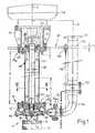
- a centrifugal pump 10 used as a submersible pump has according to Fig. 1 to a equipped with connecting flanges 12, 12 a volute casing 14 - with the interposition of not identified seals - a bearing carrier housing 20.
- a centrifugal pump 10 used as a submersible pump has according to Fig. 1 to a equipped with connecting flanges 12, 12 a volute casing 14 - with the interposition of not identified seals - a bearing carrier housing 20.
- This impeller 28 rotates in the housing space 15 of the screwed to the bearing support housing 20 spiral housing 14 to which a suction chamber 16 connects axially; the inlet of which is designated with 17, the outlet of the housing space 15 with 18.
- the inlet 17 is a Siebansatz 19 prefixed, and near the impeller 28 is located in the bearing support housing 20, a front sliding bearing 30th
- a pump shaft 24 receiving cylindrical Primaaus foundedung 34 - provided with an inner groove 33 for a seal, not shown - which in the interior 35 of a connecting piece or pipe 36 of the diameter d 1 and the length a opens.
- the connection piece 36 is fixed here at one end in a ring 22 bolted to the end face of the bearing carrier housing 20.
- a lower ring 22 which is a second bearing support housing 20 a for a second - pre-set as a ball bearing - shaft bearings.
- a radial rear plate 40 is screwed, which is penetrated by deman a drive 42 connected - shaft end 25.
- the latter is connected by a provided in a clutch housing 44 coupling device 46 with that drive not shown 42.
- the bolted to the clutch housing 44 upper bearing support housing 20 a sits in a direction indicated at 48, radially arranged support plate of thickness f.
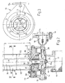
- Fig. 2 3rd are the angular profile 60 of the pressure relief hole 38 radial bar profiles 63 opposite.
- the ridge edge 62 of the fixed with its leg edges 61 on the inner surface of the connecting pipe or nozzle 36 angle profile 60 determines a radial plane Q, which also passes through the connecting flange 12 a of the outlet 18 diametrically.
- a centrifugal pump 10 e of 4 to 6 is also the impeller bearing formed as a ball bearing 31, and the connecting piece 36 of the diameter d 1 of about 135 mm and the length a of 495 mm and the angle sections 60 are set at one end in an annular groove 64 of the bearing support housing 20.
- Its inside diameter e measures 72 mm with a groove width b of 32 mm.
- the annular groove 64 is radially adjacent the aforementioned inner groove 33 for a seal, not shown.
- At this annular groove 64 includes the aforementioned ring 20 of an outer diameter e 1 of 195 mm, which is circumferentially surrounded by an edge bead 23 of the bearing support housing 20.
- the other end of the connecting piece 36 superimposed in an annular groove 66 a of a second bearing support housing 20 a for a second ball bearing 31.
- the thickness f of the here also radially the bearing support housing 20 a associated support plate 48 measures 25 mm. Their distance a 1 to the center plane E of the impeller 28 is 600 mm.
- On one side of the connecting piece 36 is in Fig. 4 a longitudinal tube 68 - at a radial distance i 1 of 85 mm of its tube axis B 1 to the shaft axis A - to recognize that opens at both ends into closable transverse channels 69, 69 a of the bearing carrier housing 20, 20 a .
- the transverse channels 69, 69 a are connected to the housing space 15 of the spiral housing 14 for the impeller 28 and with the adjacent to the rear plate 40 storage space 41 for the drive-near ball bearing 31.
- the end edge 72 of the hollow shaft 70 can be seen the end face of the central Anformung (32) of the bearing carrier housing 20, 20 a added.
- the pressure relief holes 38 are preceded by angle profiles 60 and with their leg edges 61 on the wall of the connecting piece 36 welded; whose length n measures 200 mm and their axial distance n 1 from each other about 95 mm.
- connection piece 36 located in this connection piece 36 - as above all Fig. 5, 6 can be seen - coaxial with the pump shaft 24, a hollow shaft 70 of the outer diameter t of 70 mm, which is associated with a closely surrounding interference contour 21 of the bearing housing 20, 20 a .
- Fig. 6 also that rectangular cross-section of the two pairs of angle profiles 60 becomes clear; an angle profile 60 of the mating over completely covers the associated pressure relief bore 38; this provided in the zenith of the connecting piece 36 angle section 60 is on the other side of the shaft axis A in radial distance q of about 80 mm diametrically opposite a lower angle profile 60 of the pairing.
- instead of the angle profiles 60 instead of the angle profiles 60 also - provided in accordance with cross-section - flat iron.
- the attached to the pressure relief holes 38 angle sections 60 cover these, which - as I said - the fluid is deflected and can flow back into the container without foaming. Moreover, the position of the pressure relief hole 38 is offset by 90 ° to the vent hole 68 of the centrifugal pump 10 e . Thanks to this cover of the pressure relief holes 38, the uncontrolled leakage of the fluid into a surrounding container is completely prevented. A rotation of the conveying medium in the connection piece 36 is prevented by the profile of the respective profile ridge edge 62 which is close to that interference contour 21.
- the Fig. 7, 8 show two of the illustration in Fig. 6 corresponding cross sections of other embodiments, to which Fig. 9 a reduced partial longitudinal section of the centrifugal pump 10 n offers.
- the profiled steel formed from two angle sections 60 a are with their Profilefirstkante 62 on the Inner surface of the connecting tube 36 defined on the cross-sectional central axis M, and its interior 59 opens to the interference contour 21 of the bearing support housing 20, to which the leg edges 62 a extend at a distance.
- the diametrical distance between both leg edges 62 a is denoted by q 1 .
- the pressure relief holes 38 are missing both in this sketch and in the example of Fig. 8 ; they are here replaced by radial relief holes 67, which attach in the bearing support housing 20 below the angle sections 60 a and go from the foot of the connecting piece 36 to the outside. 69 is another pressure relief hole marked.
- the Fig. 8 offers instead of that angle profile 60 a also made of section steel existing - channel profile 74 with a by a - fixed to that inner surface of the connecting tube 36 with its longitudinal contours 76 and with this a cavity 77 forming - groove bottom 75 of length g at right angles, ie parallel to Central axis M, projecting trough legs 78 of length h; the leg edges 79 are at a distance from the interference contour 21 of the bearing carrier housing 20 and at a distance q 1 to each other.
- the leg edges 61 are inclined inwardly toward the center axis M.
- the radial relief holes 67 described above are provided.
- a centrifugal pump 10 i after Fig. 10 is the pressure relief hole 38 for protection associated hollow shaft 70 of length z from here 150 mm with the inner surface of the connecting piece 36 by - preferably radially Asked - flat sections or flat bars 80 connected, the lower edges 82 with the bottom or lower end edge 72 of Hollow shaft 70 approximately aligned and so the collar-like Anformung 32 of the bearing support housing 20 sit. Towards the top, the ridge edge 71 projects beyond the hollow shaft 70 the flat bars 80 slightly.
- a sieve set 19 is connected to the connecting flange 12 of the spiral housing 14 by screws 13, moreover.
Landscapes
- Engineering & Computer Science (AREA)
- Mechanical Engineering (AREA)
- General Engineering & Computer Science (AREA)
- Physics & Mathematics (AREA)
- Fluid Mechanics (AREA)
- Structures Of Non-Positive Displacement Pumps (AREA)
- Reciprocating Pumps (AREA)
- Lubrication Of Internal Combustion Engines (AREA)
Claims (18)
- Pompe centrifuge, pour transférer un fluide à transférer, avec une roue mobile (28) prévue dans un carter en spirale (14), ainsi qu'un carter de support de palier (20), associé au carter en spirale (14), pour au moins un palier (30, 31) d'un arbre de pompe (24), raccordé à la roue mobile (28), traversant, à l'autre extrémité, un autre carter de support de palier (20a) et raccordé, au-delà de celui-ci, à un entraînement (42), un tube de liaison (36), entourant l'arbre de pompe (24), s'étendant entre les carters de support de palier (20, 20a),
caractérisée en ce que
au moins un perçage de décharge de pression (28) est prévu dans la paroi du tube de liaison ou de la tubulure de liaison (36) et, à ce perçage de décharge de pression (28) est associé, du côté intérieur, un profilé creux partiel (60, 60a, 74) le recouvrant, s'étendant parallèlement à l'axe d'arbre (A) et à distance radiale de l'arbre de pompe (24), en ce qu'au moins un perçage de décharge de pression (67) au-dessous des/du profilé(s) creux partiel(s) (60a, 74) est amené à travers le carter de support de palier (20, 20a) voisin de celui-ci/ceux-ci. - Pompe centrifuge selon la revendication 1, caractérisée en ce que le profilé creux partiel (60, 60a, 74) est un profilé creux divisé parallèlement à son axe longitudinal (A) et conformé en goulotte.
- Pompe centrifuge selon la revendication 1 ou 2, caractérisée en ce que, de chacun des carters de supports de palier (20, 20a), part un profilé creux partiel (60, 60a, 74), entourant au moins un perçage de décharge de pression (38) voisin du carter de support de palier, le cas échéant les deux profilés creux partiels (60, 60a, 74) étant alignés entre eux et s'achevant à une distance (n1) l'un de l'autre.
- Pompe centrifuge selon l'une des revendications 1 à 3, caractérisée en ce que le profilé creux partiel est un profilé en cornière (60), fixé, du côté intérieur, par ses arêtes de branches (61), de part et d'autre du ou des perçages(s) de décharge de pression (38) sur la tubulure de liaison (36), et dont l'arête de faîte de profilé (62) s'étend à distance de l'arbre de pompe (24).
- Pompe centrifuge selon l'une des revendications 1 à 3, caractérisée en ce que le profilé creux partiel est un profilé en cornière (60a), fixé, du côté intérieur, par son arête de faîte de profilé (62), sur la tubulure de liaison (36), et dont les arêtes de branches (61) s'étendent à distance de l'arbre de pompe (24).
- Pompe centrifuge selon l'une des revendications 1 à 3, caractérisée en ce que le profilé creux partiel est un profilé en goulotte (74), dont le fond de goulotte est fixé, côté intérieur, de part et d'autre, sur la tubulure de liaison (36), et dont les branches de goulotte (78) font saillie par rapport à la tubulure de liaison (36), le cas échant le profilé en goulotte (74) présentant une section transversale rectangulaire.
- Pompe centrifuge selon la revendication 6, caractérisée en ce que les arêtes de branche (79) des branches de goulotte (78) sont, en section transversale, inclinées par rapport au fond de goulotte (75) et/ou en ce que les arêtes de branche (79) des branches de goulotte (78) s'étendent à distance de l'arbre de pompe (24).
- Pompe centrifuge selon l'une des revendications 1, 5 à 7, caractérisée en ce que le/les perçages(s) de décharge de pression (67) sont associés aux profilés en cornière (60a) s'ouvrant côté axe, ou aux profils en goulotte (74).
- Pompe centrifuge selon l'une des revendications 1 à 8, caractérisée en ce qu'un autre profilé (60, 60a, 74 ; 63), de préférence un profilé de configuration identique, est situé diamétralement à l'opposé du profilé creux partiel ou en cornière (60, 60a, 74) recouvrant le/les perçages(s) de décharge de pression (38).
- Pompe centrifuge selon l'une des revendications 1 à 4, caractérisée en ce qu'au moins deux autres profilés, de préférence des profilés à âme (63) radiaux, font saillie l'un par rapport à l'autre, à distance radiale, de la zone de paroi, opposée au profilé creux partiel ou en cornière (60), de la tubulure de liaison (36).
- Pompe centrifuge selon l'une quelconque des revendications 1 à 10, caractérisée en ce que la tubulure de liaison (36) est disposée, à l'extrémité, avec une extrémité du/des profilé(s) (60, 63) fixé(s) en elle côté intérieur, dans une gorge annulaire (64) du carter de support de palier (20, 20a).
- Pompe centrifuge selon l'une des revendications 1 à 11, caractérisée en ce que le/les perçages(s) de décharge de pression (38) et leur(s) profilé(s) creux partiel(s) ou en cornière (60) sont situés dans un plan radial (Q), dans lequel se trouve l'échappement (18) du carter en spirale (14).
- Pompe centrifuge selon l'une des revendications 1 à 12, caractérisée en ce que l'arbre de pompe (24) est entouré par un arbre creux (70), et celui-ci est disposé à distance radiale du/des profilé(s) (60, 60a, 74 ; 63), le cas échéant l'arbre creux (70), par son arête d'extrémité (72), appuyant sur un bossage (32) central du carter de support de palier (20, 20a), traversé par l'arbre de pompe (24).
- Pompe centrifuge selon la revendication 13, caractérisée en ce qu'un contour perturbateur (21) est voisin de la surface extérieure de l'arbre creux (70), sur la surface frontale du carter de support de palier (20, 20a).
- Pompe centrifuge selon la revendication 13 ou 14, caractérisée en ce que la distance radiale entre arbre de pompe (24) et arbre creux (70) correspond à peu près à son espacement radial par rapport à/aux arête(s) de faîte de profilé (62).
- Pompe centrifuge selon l'une des revendications 1 à 15, caractérisée en ce que, sur la surface extérieure de la tubulure de liaison (36) s'étend un tube allongé (66), reliant ensemble des canaux transversaux (68) dans les deux carters de supports de palier (20, 20a), le cas échéant le tube allongé (66) étant orienté parallèlement à l'axe d'arbre (A).
- Pompe centrifuge selon l'une des revendications 10 à 16, caractérisée en ce que l'arbre creux (70) entoure le pied de l'arbre de pompe (24).
- Pompe centrifuge selon l'une des revendications 1 à 16, caractérisée en ce que le profilé creux partiel est composé de plusieurs composants, couvrant le/les perçage(s) de décharge de pression (36), le cas échéant des profilés plats (80) faisant saillie, dans la direction de l'axe, de la surface intérieure de la tubulure de liaison (36), et/ou l'arbre creux (70) est relié, par des profilés plats (80), à la surface intérieure de la tubulure de liaison (36).
Applications Claiming Priority (3)
| Application Number | Priority Date | Filing Date | Title |
|---|---|---|---|
| DE10237352 | 2002-08-12 | ||
| DE10237352 | 2002-08-12 | ||
| PCT/EP2003/008697 WO2004022979A1 (fr) | 2002-08-12 | 2003-08-06 | Pompe centrifuge |
Publications (2)
| Publication Number | Publication Date |
|---|---|
| EP1529167A1 EP1529167A1 (fr) | 2005-05-11 |
| EP1529167B1 true EP1529167B1 (fr) | 2010-03-17 |
Family
ID=30775290
Family Applications (1)
| Application Number | Title | Priority Date | Filing Date |
|---|---|---|---|
| EP03793695A Expired - Lifetime EP1529167B1 (fr) | 2002-08-12 | 2003-08-06 | Pompe centrifuge |
Country Status (5)
| Country | Link |
|---|---|
| EP (1) | EP1529167B1 (fr) |
| AT (1) | ATE461367T1 (fr) |
| DE (3) | DE10256792B4 (fr) |
| ES (1) | ES2342597T3 (fr) |
| WO (1) | WO2004022979A1 (fr) |
Families Citing this family (8)
| Publication number | Priority date | Publication date | Assignee | Title |
|---|---|---|---|---|
| US7492069B2 (en) * | 2001-04-19 | 2009-02-17 | Baker Hughes Incorporated | Pressurized bearing system for submersible motor |
| DE102005013684A1 (de) * | 2005-03-17 | 2006-09-21 | Flux-Geräte GmbH | Behälterpumpe, vorzugsweise zum Fördern von Harnstoff |
| CN107152407A (zh) * | 2017-06-21 | 2017-09-12 | 江苏建安泵业制造有限公司 | 一种输送颗粒及粘度介质的涂装用液下泵 |
| WO2022249056A1 (fr) | 2021-05-24 | 2022-12-01 | Flsmidth A/S | Pompe à réservoir ayant une entrée d'alimentation tangentielle et une tablette d'alimentation à géométrie variable |
| CN113357159B (zh) * | 2021-07-05 | 2022-05-31 | 陈荣国 | 基于直流永磁电机的自吸式复合屏蔽泵 |
| CN115788919A (zh) | 2021-09-09 | 2023-03-14 | 创科无线普通合伙 | 潜水泵 |
| US20250172159A1 (en) * | 2022-04-15 | 2025-05-29 | Weir Pump and Valve Solutions, Inc. | Centrifugal Pump Casing With Strainer Device Attachment |
| WO2023218426A1 (fr) | 2022-05-12 | 2023-11-16 | Flsmidth A/S | Système de transport de mousse, dispositif de désaération, et procédé de pompage efficace de boues mousseuses ou aérées |
Family Cites Families (8)
| Publication number | Priority date | Publication date | Assignee | Title |
|---|---|---|---|---|
| DE747143C (de) * | 1941-04-04 | 1944-09-11 | Galassi Ortolani & Mueller | Kreiselpumpe |
| US3731940A (en) * | 1971-08-06 | 1973-05-08 | W Spruiell | Elastomer seal with a plurality of annular ribs for a rotating shaft of a centrifugal pump or the like |
| DE2262017C3 (de) * | 1972-12-19 | 1981-07-02 | H. Wernert & Co Kg, 4330 Muelheim | Vertikale, hängende Kreiselpumpe |
| US3936221A (en) * | 1974-09-16 | 1976-02-03 | Goulds Pumps, Inc. | Vertical cantilever pump |
| US4394140A (en) * | 1977-12-30 | 1983-07-19 | Smith International, Inc. | Degassing system and centrifugal pump |
| FR2717535A1 (fr) * | 1994-03-17 | 1995-09-22 | Siebec Sa | Pompe verticale. |
| US6315530B1 (en) * | 1999-10-05 | 2001-11-13 | Buffalo Pumps, Inc. | Submerged pump having a shaft isolator |
| DE10051324C1 (de) * | 2000-10-17 | 2002-02-21 | Brinkmann Pumpen K H Brinkmann | Flüssigkeitspumpe mit Spritzschutz |
-
2002
- 2002-12-05 DE DE10256792A patent/DE10256792B4/de not_active Expired - Lifetime
-
2003
- 2003-08-06 EP EP03793695A patent/EP1529167B1/fr not_active Expired - Lifetime
- 2003-08-06 DE DE50312528T patent/DE50312528D1/de not_active Expired - Lifetime
- 2003-08-06 WO PCT/EP2003/008697 patent/WO2004022979A1/fr not_active Ceased
- 2003-08-06 AT AT03793695T patent/ATE461367T1/de not_active IP Right Cessation
- 2003-08-06 ES ES03793695T patent/ES2342597T3/es not_active Expired - Lifetime
- 2003-08-07 DE DE10336947A patent/DE10336947A1/de not_active Withdrawn
Also Published As
| Publication number | Publication date |
|---|---|
| WO2004022979A1 (fr) | 2004-03-18 |
| DE50312528D1 (de) | 2010-04-29 |
| ES2342597T3 (es) | 2010-07-09 |
| DE10336947A1 (de) | 2004-02-26 |
| DE10256792A1 (de) | 2004-03-04 |
| ATE461367T1 (de) | 2010-04-15 |
| EP1529167A1 (fr) | 2005-05-11 |
| DE10256792B4 (de) | 2005-01-13 |
Similar Documents
| Publication | Publication Date | Title |
|---|---|---|
| DE2130474C3 (de) | Zentrifugalpumpe | |
| DE69629606T2 (de) | Pumpe mit einem verbesserten Durchflusskanal | |
| DE69329657T2 (de) | Pumpengehäuse in Blechbauweise | |
| CH628116A5 (en) | Submersible pump, especially drum pump | |
| EP1529167B1 (fr) | Pompe centrifuge | |
| DE102007032228A1 (de) | Selbstansaugende Pumpenaggregation | |
| DE7507522U (de) | Kreiselpumpe | |
| DE3517828A1 (de) | Pumpengehaeuse | |
| DE1403540A1 (de) | Pumpe | |
| EP3085961A1 (fr) | Pompe centrifuge à plusieurs etages | |
| DE2262017C3 (de) | Vertikale, hängende Kreiselpumpe | |
| EP1148248A2 (fr) | Carter de pompe | |
| DE102007012661B4 (de) | Tauchpumpenaggregat | |
| EP3978760B1 (fr) | Pompe centrifuge submersible | |
| DE2522165A1 (de) | Kreiselpumpe | |
| DE9208801U1 (de) | Pumpenaggregat | |
| DE4239071A1 (de) | Tauchpumpenaggregat | |
| DE29823424U1 (de) | Kreiselpumpe mit Gleitringdichtung | |
| DE19834012C2 (de) | Kreiselpumpe mit Gleitringdichtung | |
| DE10112018A1 (de) | Tauchpumpe, insbesondere für Abwasser, Gülle oder dickflüssige Massen | |
| EP1411249B1 (fr) | Unité de pompage | |
| EP0995906A1 (fr) | Pompe centrifuge double entrainée par un moteur | |
| DE102006006253A1 (de) | Pumpwerk | |
| DE4231785A1 (de) | Radialkolbenpumpe mit integriertem Resonator | |
| DE102020125824A1 (de) | Tauchkreiselpumpe |
Legal Events
| Date | Code | Title | Description |
|---|---|---|---|
| PUAI | Public reference made under article 153(3) epc to a published international application that has entered the european phase |
Free format text: ORIGINAL CODE: 0009012 |
|
| 17P | Request for examination filed |
Effective date: 20040423 |
|
| AK | Designated contracting states |
Kind code of ref document: A1 Designated state(s): AT BE BG CH CY CZ DE DK EE ES FI FR GB GR HU IE IT LI LU MC NL PT RO SE SI SK TR |
|
| RIN1 | Information on inventor provided before grant (corrected) |
Inventor name: WEIDELE, EDGAR |
|
| GRAP | Despatch of communication of intention to grant a patent |
Free format text: ORIGINAL CODE: EPIDOSNIGR1 |
|
| GRAS | Grant fee paid |
Free format text: ORIGINAL CODE: EPIDOSNIGR3 |
|
| GRAA | (expected) grant |
Free format text: ORIGINAL CODE: 0009210 |
|
| AK | Designated contracting states |
Kind code of ref document: B1 Designated state(s): AT BE BG CH CY CZ DE DK EE ES FI FR GB GR HU IE IT LI LU MC NL PT RO SE SI SK TR |
|
| REG | Reference to a national code |
Ref country code: GB Ref legal event code: FG4D Free format text: NOT ENGLISH |
|
| REG | Reference to a national code |
Ref country code: CH Ref legal event code: EP |
|
| REG | Reference to a national code |
Ref country code: IE Ref legal event code: FG4D |
|
| REF | Corresponds to: |
Ref document number: 50312528 Country of ref document: DE Date of ref document: 20100429 Kind code of ref document: P |
|
| REG | Reference to a national code |
Ref country code: CH Ref legal event code: NV Representative=s name: BODENSEEPATENT GMBH |
|
| REG | Reference to a national code |
Ref country code: SE Ref legal event code: TRGR |
|
| REG | Reference to a national code |
Ref country code: ES Ref legal event code: FG2A Ref document number: 2342597 Country of ref document: ES Kind code of ref document: T3 |
|
| REG | Reference to a national code |
Ref country code: NL Ref legal event code: VDEP Effective date: 20100317 |
|
| PG25 | Lapsed in a contracting state [announced via postgrant information from national office to epo] |
Ref country code: SI Free format text: LAPSE BECAUSE OF FAILURE TO SUBMIT A TRANSLATION OF THE DESCRIPTION OR TO PAY THE FEE WITHIN THE PRESCRIBED TIME-LIMIT Effective date: 20100317 |
|
| REG | Reference to a national code |
Ref country code: IE Ref legal event code: FD4D |
|
| PG25 | Lapsed in a contracting state [announced via postgrant information from national office to epo] |
Ref country code: CY Free format text: LAPSE BECAUSE OF FAILURE TO SUBMIT A TRANSLATION OF THE DESCRIPTION OR TO PAY THE FEE WITHIN THE PRESCRIBED TIME-LIMIT Effective date: 20100317 Ref country code: EE Free format text: LAPSE BECAUSE OF FAILURE TO SUBMIT A TRANSLATION OF THE DESCRIPTION OR TO PAY THE FEE WITHIN THE PRESCRIBED TIME-LIMIT Effective date: 20100317 Ref country code: RO Free format text: LAPSE BECAUSE OF FAILURE TO SUBMIT A TRANSLATION OF THE DESCRIPTION OR TO PAY THE FEE WITHIN THE PRESCRIBED TIME-LIMIT Effective date: 20100317 Ref country code: NL Free format text: LAPSE BECAUSE OF FAILURE TO SUBMIT A TRANSLATION OF THE DESCRIPTION OR TO PAY THE FEE WITHIN THE PRESCRIBED TIME-LIMIT Effective date: 20100317 Ref country code: GR Free format text: LAPSE BECAUSE OF FAILURE TO SUBMIT A TRANSLATION OF THE DESCRIPTION OR TO PAY THE FEE WITHIN THE PRESCRIBED TIME-LIMIT Effective date: 20100618 |
|
| PG25 | Lapsed in a contracting state [announced via postgrant information from national office to epo] |
Ref country code: CZ Free format text: LAPSE BECAUSE OF FAILURE TO SUBMIT A TRANSLATION OF THE DESCRIPTION OR TO PAY THE FEE WITHIN THE PRESCRIBED TIME-LIMIT Effective date: 20100317 Ref country code: SK Free format text: LAPSE BECAUSE OF FAILURE TO SUBMIT A TRANSLATION OF THE DESCRIPTION OR TO PAY THE FEE WITHIN THE PRESCRIBED TIME-LIMIT Effective date: 20100317 Ref country code: BG Free format text: LAPSE BECAUSE OF FAILURE TO SUBMIT A TRANSLATION OF THE DESCRIPTION OR TO PAY THE FEE WITHIN THE PRESCRIBED TIME-LIMIT Effective date: 20100617 |
|
| PLBE | No opposition filed within time limit |
Free format text: ORIGINAL CODE: 0009261 |
|
| STAA | Information on the status of an ep patent application or granted ep patent |
Free format text: STATUS: NO OPPOSITION FILED WITHIN TIME LIMIT |
|
| PG25 | Lapsed in a contracting state [announced via postgrant information from national office to epo] |
Ref country code: PT Free format text: LAPSE BECAUSE OF FAILURE TO SUBMIT A TRANSLATION OF THE DESCRIPTION OR TO PAY THE FEE WITHIN THE PRESCRIBED TIME-LIMIT Effective date: 20100719 Ref country code: DK Free format text: LAPSE BECAUSE OF FAILURE TO SUBMIT A TRANSLATION OF THE DESCRIPTION OR TO PAY THE FEE WITHIN THE PRESCRIBED TIME-LIMIT Effective date: 20100317 Ref country code: IE Free format text: LAPSE BECAUSE OF FAILURE TO SUBMIT A TRANSLATION OF THE DESCRIPTION OR TO PAY THE FEE WITHIN THE PRESCRIBED TIME-LIMIT Effective date: 20100317 |
|
| 26N | No opposition filed |
Effective date: 20101220 |
|
| BERE | Be: lapsed |
Owner name: ALLWEILER A.G. Effective date: 20100831 |
|
| PG25 | Lapsed in a contracting state [announced via postgrant information from national office to epo] |
Ref country code: MC Free format text: LAPSE BECAUSE OF NON-PAYMENT OF DUE FEES Effective date: 20100831 |
|
| PG25 | Lapsed in a contracting state [announced via postgrant information from national office to epo] |
Ref country code: BE Free format text: LAPSE BECAUSE OF NON-PAYMENT OF DUE FEES Effective date: 20100831 |
|
| PGFP | Annual fee paid to national office [announced via postgrant information from national office to epo] |
Ref country code: CH Payment date: 20110824 Year of fee payment: 9 |
|
| PG25 | Lapsed in a contracting state [announced via postgrant information from national office to epo] |
Ref country code: AT Free format text: LAPSE BECAUSE OF NON-PAYMENT OF DUE FEES Effective date: 20100806 |
|
| REG | Reference to a national code |
Ref country code: DE Ref legal event code: R082 Ref document number: 50312528 Country of ref document: DE Representative=s name: BEHRMANN WAGNER VOETSCH, DE |
|
| REG | Reference to a national code |
Ref country code: DE Ref legal event code: R082 Ref document number: 50312528 Country of ref document: DE Representative=s name: BEHRMANN WAGNER VOETSCH, DE Ref country code: CH Ref legal event code: PFA Owner name: ALLWEILER GMBH Free format text: ALLWEILER AG#POSTFACH 1140#D-78301 RADOLFZELL (DE) -TRANSFER TO- ALLWEILER GMBH#POSTFACH 1140#78301 RADOLFZELL (DE) |
|
| REG | Reference to a national code |
Ref country code: DE Ref legal event code: R082 Ref document number: 50312528 Country of ref document: DE Representative=s name: MURGITROYD & COMPANY, DE Effective date: 20120413 Ref country code: DE Ref legal event code: R082 Ref document number: 50312528 Country of ref document: DE Representative=s name: MURGITROYD & COMPANY, DE Effective date: 20120405 Ref country code: DE Ref legal event code: R082 Ref document number: 50312528 Country of ref document: DE Representative=s name: PATENTANWAELTE BEHRMANN WAGNER PARTNERSCHAFTSG, DE Effective date: 20120405 Ref country code: DE Ref legal event code: R081 Ref document number: 50312528 Country of ref document: DE Owner name: ALLWEILER GMBH, DE Free format text: FORMER OWNER: ALLWEILER AG, 78315 RADOLFZELL, DE Effective date: 20120405 Ref country code: DE Ref legal event code: R082 Ref document number: 50312528 Country of ref document: DE Representative=s name: PATENTANWAELTE BEHRMANN WAGNER PARTNERSCHAFTSG, DE Effective date: 20120413 |
|
| PG25 | Lapsed in a contracting state [announced via postgrant information from national office to epo] |
Ref country code: HU Free format text: LAPSE BECAUSE OF FAILURE TO SUBMIT A TRANSLATION OF THE DESCRIPTION OR TO PAY THE FEE WITHIN THE PRESCRIBED TIME-LIMIT Effective date: 20100918 Ref country code: LU Free format text: LAPSE BECAUSE OF NON-PAYMENT OF DUE FEES Effective date: 20100806 |
|
| REG | Reference to a national code |
Ref country code: ES Ref legal event code: PC2A Owner name: ALLWEILER GMBH Effective date: 20120919 |
|
| PG25 | Lapsed in a contracting state [announced via postgrant information from national office to epo] |
Ref country code: TR Free format text: LAPSE BECAUSE OF FAILURE TO SUBMIT A TRANSLATION OF THE DESCRIPTION OR TO PAY THE FEE WITHIN THE PRESCRIBED TIME-LIMIT Effective date: 20100317 |
|
| PGFP | Annual fee paid to national office [announced via postgrant information from national office to epo] |
Ref country code: FI Payment date: 20120822 Year of fee payment: 10 Ref country code: SE Payment date: 20120823 Year of fee payment: 10 Ref country code: GB Payment date: 20120823 Year of fee payment: 10 |
|
| PGFP | Annual fee paid to national office [announced via postgrant information from national office to epo] |
Ref country code: IT Payment date: 20120825 Year of fee payment: 10 Ref country code: ES Payment date: 20120824 Year of fee payment: 10 Ref country code: FR Payment date: 20120831 Year of fee payment: 10 |
|
| REG | Reference to a national code |
Ref country code: CH Ref legal event code: PL |
|
| REG | Reference to a national code |
Ref country code: SE Ref legal event code: EUG |
|
| GBPC | Gb: european patent ceased through non-payment of renewal fee |
Effective date: 20130806 |
|
| PG25 | Lapsed in a contracting state [announced via postgrant information from national office to epo] |
Ref country code: SE Free format text: LAPSE BECAUSE OF NON-PAYMENT OF DUE FEES Effective date: 20130807 Ref country code: LI Free format text: LAPSE BECAUSE OF NON-PAYMENT OF DUE FEES Effective date: 20130831 Ref country code: CH Free format text: LAPSE BECAUSE OF NON-PAYMENT OF DUE FEES Effective date: 20130831 Ref country code: FI Free format text: LAPSE BECAUSE OF NON-PAYMENT OF DUE FEES Effective date: 20130806 |
|
| REG | Reference to a national code |
Ref country code: FR Ref legal event code: ST Effective date: 20140430 |
|
| PG25 | Lapsed in a contracting state [announced via postgrant information from national office to epo] |
Ref country code: IT Free format text: LAPSE BECAUSE OF NON-PAYMENT OF DUE FEES Effective date: 20130806 |
|
| PG25 | Lapsed in a contracting state [announced via postgrant information from national office to epo] |
Ref country code: GB Free format text: LAPSE BECAUSE OF NON-PAYMENT OF DUE FEES Effective date: 20130806 |
|
| PG25 | Lapsed in a contracting state [announced via postgrant information from national office to epo] |
Ref country code: FR Free format text: LAPSE BECAUSE OF NON-PAYMENT OF DUE FEES Effective date: 20130902 |
|
| REG | Reference to a national code |
Ref country code: DE Ref legal event code: R082 Ref document number: 50312528 Country of ref document: DE Representative=s name: MURGITROYD & COMPANY, DE |
|
| REG | Reference to a national code |
Ref country code: ES Ref legal event code: FD2A Effective date: 20150709 |
|
| PG25 | Lapsed in a contracting state [announced via postgrant information from national office to epo] |
Ref country code: ES Free format text: LAPSE BECAUSE OF NON-PAYMENT OF DUE FEES Effective date: 20130807 |
|
| PGFP | Annual fee paid to national office [announced via postgrant information from national office to epo] |
Ref country code: DE Payment date: 20220608 Year of fee payment: 20 |
|
| REG | Reference to a national code |
Ref country code: DE Ref legal event code: R071 Ref document number: 50312528 Country of ref document: DE |